EP2177130B1 - Faltbare Platte - Google Patents
Faltbare Platte Download PDFInfo
- Publication number
- EP2177130B1 EP2177130B1 EP09170302.5A EP09170302A EP2177130B1 EP 2177130 B1 EP2177130 B1 EP 2177130B1 EP 09170302 A EP09170302 A EP 09170302A EP 2177130 B1 EP2177130 B1 EP 2177130B1
- Authority
- EP
- European Patent Office
- Prior art keywords
- layer
- plate
- foldable
- furniture
- foldable plate
- Prior art date
- Legal status (The legal status is an assumption and is not a legal conclusion. Google has not performed a legal analysis and makes no representation as to the accuracy of the status listed.)
- Active
Links
- 239000003973 paint Substances 0.000 claims description 14
- 230000009477 glass transition Effects 0.000 claims description 6
- 239000006185 dispersion Substances 0.000 claims description 4
- 239000000203 mixture Substances 0.000 claims description 4
- 229920002681 hypalon Polymers 0.000 claims description 3
- 229920001971 elastomer Polymers 0.000 claims description 2
- 239000000806 elastomer Substances 0.000 claims description 2
- 229920002635 polyurethane Polymers 0.000 claims description 2
- 239000004814 polyurethane Substances 0.000 claims description 2
- 229920002050 silicone resin Polymers 0.000 claims description 2
- -1 acryl Chemical group 0.000 claims 1
- YACLQRRMGMJLJV-UHFFFAOYSA-N chloroprene Chemical compound ClC(=C)C=C YACLQRRMGMJLJV-UHFFFAOYSA-N 0.000 claims 1
- 150000002118 epoxides Chemical class 0.000 claims 1
- 230000005923 long-lasting effect Effects 0.000 claims 1
- 239000010410 layer Substances 0.000 description 108
- 239000004922 lacquer Substances 0.000 description 34
- 238000004806 packaging method and process Methods 0.000 description 12
- 239000002966 varnish Substances 0.000 description 10
- 230000008901 benefit Effects 0.000 description 9
- 239000005022 packaging material Substances 0.000 description 8
- 238000003825 pressing Methods 0.000 description 7
- 238000004519 manufacturing process Methods 0.000 description 5
- 238000000576 coating method Methods 0.000 description 4
- 230000002045 lasting effect Effects 0.000 description 4
- 230000002787 reinforcement Effects 0.000 description 4
- 230000000007 visual effect Effects 0.000 description 4
- 239000000853 adhesive Substances 0.000 description 3
- 230000001070 adhesive effect Effects 0.000 description 3
- 238000005452 bending Methods 0.000 description 3
- 238000004040 coloring Methods 0.000 description 3
- 239000000835 fiber Substances 0.000 description 3
- 239000000463 material Substances 0.000 description 3
- 239000002390 adhesive tape Substances 0.000 description 2
- 230000000694 effects Effects 0.000 description 2
- 239000004744 fabric Substances 0.000 description 2
- 230000001771 impaired effect Effects 0.000 description 2
- 239000000047 product Substances 0.000 description 2
- 239000002023 wood Substances 0.000 description 2
- 241001553178 Arachis glabrata Species 0.000 description 1
- 239000004593 Epoxy Substances 0.000 description 1
- 229910000831 Steel Inorganic materials 0.000 description 1
- NIXOWILDQLNWCW-UHFFFAOYSA-N acrylic acid group Chemical group C(C=C)(=O)O NIXOWILDQLNWCW-UHFFFAOYSA-N 0.000 description 1
- 239000012790 adhesive layer Substances 0.000 description 1
- 239000001913 cellulose Substances 0.000 description 1
- 229920002678 cellulose Polymers 0.000 description 1
- 238000006243 chemical reaction Methods 0.000 description 1
- 239000011093 chipboard Substances 0.000 description 1
- 239000011248 coating agent Substances 0.000 description 1
- 238000007906 compression Methods 0.000 description 1
- 230000006835 compression Effects 0.000 description 1
- 238000001816 cooling Methods 0.000 description 1
- 238000007907 direct compression Methods 0.000 description 1
- 238000009826 distribution Methods 0.000 description 1
- 239000003344 environmental pollutant Substances 0.000 description 1
- 239000011094 fiberboard Substances 0.000 description 1
- 239000000945 filler Substances 0.000 description 1
- 238000000227 grinding Methods 0.000 description 1
- 238000010438 heat treatment Methods 0.000 description 1
- 230000006872 improvement Effects 0.000 description 1
- 230000003993 interaction Effects 0.000 description 1
- 239000007788 liquid Substances 0.000 description 1
- 238000010943 off-gassing Methods 0.000 description 1
- 230000003287 optical effect Effects 0.000 description 1
- 239000000123 paper Substances 0.000 description 1
- 235000020232 peanut Nutrition 0.000 description 1
- 239000004033 plastic Substances 0.000 description 1
- 229920003023 plastic Polymers 0.000 description 1
- 231100000719 pollutant Toxicity 0.000 description 1
- 238000002360 preparation method Methods 0.000 description 1
- 230000037452 priming Effects 0.000 description 1
- 230000009467 reduction Effects 0.000 description 1
- 229920006395 saturated elastomer Polymers 0.000 description 1
- 230000006641 stabilisation Effects 0.000 description 1
- 238000011105 stabilization Methods 0.000 description 1
- 239000010959 steel Substances 0.000 description 1
- 239000000126 substance Substances 0.000 description 1
- 239000000758 substrate Substances 0.000 description 1
- 239000013589 supplement Substances 0.000 description 1
- 229920003002 synthetic resin Polymers 0.000 description 1
- 239000000057 synthetic resin Substances 0.000 description 1
Images


Classifications
-
- A—HUMAN NECESSITIES
- A47—FURNITURE; DOMESTIC ARTICLES OR APPLIANCES; COFFEE MILLS; SPICE MILLS; SUCTION CLEANERS IN GENERAL
- A47B—TABLES; DESKS; OFFICE FURNITURE; CABINETS; DRAWERS; GENERAL DETAILS OF FURNITURE
- A47B96/00—Details of cabinets, racks or shelf units not covered by a single one of groups A47B43/00 - A47B95/00; General details of furniture
- A47B96/20—Furniture panels or like furniture elements
- A47B96/202—Furniture panels or like furniture elements with a continuous layer allowing folding
Definitions
- the invention relates to a foldable plate having a visible side and a rear side, with a base plate, with a layer arranged on the base plate and with at least one formed on the back groove, wherein the layer is arranged on the visible side of the plate, wherein the layer is formed is that it has a hinge function in the region of the groove and wherein the plate is foldable along the groove
- Foldable panels are used in particular as part of furniture kits, both body parts and furniture back walls can consist of foldable panels.
- the advantage of foldability lies in the fact that the panels have a smaller dimension in the folded state and thus can be packed in smaller packages.
- the foldable panels are usually completely folded together, possibly arranged on or under other furniture components and packed with a cardboard material.
- the plates are in the usual way a folding, but also folding plates are known, which can be folded at two or more places.
- Foldable plates are known from the prior art, which consist of two adjacent plate parts, which are connected on the visible side by a PVC layer, which has a hinge function in the contact area of the plate parts.
- PVC layers have an unsuitable for furniture surfaces, undesirable or unsatisfactory surface structure, so that the visual or haptic impression of the furniture part can be affected.
- the furniture industry has strayed from the use of such foldable plates and has preferably used foldable plates, the hinge function is taken over by an adhesive or by an adhesive tape on the visible side, the back or between the plate parts.
- the DE 20 2005 018 809 U1 a foldable plate with two separate plate parts, which are held together on the back by a hinge consisting of an adhesive element.
- the JP 53064289 A discloses a foldable panel, wherein the layer forming the visible side comprises an adhesive layer, a decorative layer and two plastic layers.
- the layer on the base plate is made of a saturated paper.
- the present invention is therefore based on the object to provide a foldable plate which avoids the above-mentioned disadvantages of the foldable plates of the prior art and which is particularly simple and inexpensive to manufacture.
- the layer consists of a lacquer layer, which consists of a permanently elastic lacquer, ensures that the foldable plate has both a high durability and rigidity as well as a high ecological compatibility and a visually and haptically high-quality visible side, especially not is affected by a visible folding edge.
- the invention overcomes the technical prejudice that it requires an adhesive, an adhesive tape or even a PVC layer as a hinge element for a foldable plate. It has been found that the layer consisting of an elastic lacquer is suitable for assuming a hinge function both when folding and unfolding the plate and for giving the unfolded plate sufficient rigidity. Under a varnish, from which the varnish layer is produced, is understood to mean any form of coating material which can be applied to the plate in a liquid or powdery state.
- the arranged on the back of the plate groove preferably extends through the entire base plate thickness, so that the groove bottom exclusively through the layer or through the Paint layer is formed. Alternatively, it is also conceivable that the groove does not reach through the entire base plate.
- the groove may be I-shaped, V-shaped or otherwise formed.
- the base plate is preferably made of a wood or a wood material. For example, a chipboard or fiberboard or a multilayer board with chip and / or fiber components can be used.
- An advantageous embodiment of the foldable plate is that in the base plate a plurality of juxtaposed grooves are formed. This ensures that the total angle by which the foldable plate is folded is distributed over a plurality of folding edges, so that the folding angle at each individual groove or folding edge is less than the overall angle and reduces the mechanical stress acting as a hinge element layer in this area becomes. Thus, it is possible to make the layer thinner or to achieve a higher durability of the layer and to allow more frequent folding and unfolding of the plate.
- a decorative layer on the lacquer layer.
- a decorative layer By this configuration it is achieved that the nature of the visible side of the foldable plate can be chosen freely.
- a very thin lacquer layer or a lacquer layer with a structured surface can be used which in itself does not serve as a hinge element would be suitable.
- more than one further layer is applied to the lacquer layer in order, for example, to achieve a specific decorative effect.
- the layer forming the visible side has a reinforcement or a reinforcement.
- This reinforcement can be arranged for example in the lacquer layer or in another layer.
- fibers which are embedded in the layer are suitable for the reinforcement of such a layer.
- the lacquer layer consists essentially of a lacquer which has a glass transition temperature in the range of normal room temperatures.
- a further advantageous embodiment of the foldable plate is that the lacquer layer has a glass transition temperature between 15 ° C and 30 ° C.
- a glass transition temperature is understood as the temperature at which the curve of the logarithmic modulus of elasticity has a point of inflection. The range around the glass transition temperature is thus due to a strong temperature dependence of the logarithmic modulus of elasticity characterized.
- the use of a paint having a glass transition temperature in the range of room temperature has the advantage that the elastic modulus of the paint a takes advantageous average, so that the paint has both a sufficient bending ability and a sufficient toughness.
- the plate can be folded easily and has a high rigidity when unfolded. Furthermore, even by a slight heating of the paint in the region of the groove, the modulus of elasticity can be greatly reduced, so that the folding of the plate is further simplified. When cooling the unfolded plate to the room air, the elastic modulus increases again, so that the rigidity of the plate is increased again.
- the lacquer layer has a depth value according to Erichsen of at least 5 mm, preferably 8 mm and in particular at least 10 mm and / or the mandrel bending test according to EN ISO 6860 with a bending mandrel diameter of at most 10 mm, preferably at most 6 mm, in particular at most 4 mm.
- Erichsen depth value is understood to mean the depth to which a hardened, polished steel ball with a diameter of 20 mm can be pressed into the lacquer layer by means of a tappet at a uniform feed rate of about 0.2 mm / s before settling on the Surface of the paint layer first cracks form.
- the use of such a lacquer layer is advantageous because such a high durability of the lacquer layer is achieved and frequent folding or unfolding of the plate is made possible.
- a further advantageous embodiment of the foldable plate is given by the fact that the lacquer layer is based on solutions and dispersions of elastic chloroprenes and / or chlorosulfonated polyethylene products.
- Such Lacquer coatings are characterized by a particularly high and lasting elasticity.
- a further advantageous embodiment of the foldable plate is given by the fact that the lacquer layer is based on solutions and dispersions of silicone resins and / or elastically adjusted polyurethanes. These paint layers are characterized by a particularly high and lasting elasticity.
- a further advantageous embodiment of the foldable plate is that the lacquer layer has an epoxy or acrylic component or mixtures thereof. Such coatings are also characterized by a particularly high and lasting elasticity.
- a further advantageous embodiment of the foldable plate is that the lacquer layer is at least partially formed from an elastomer.
- Such coatings are characterized by a particularly high and lasting elasticity.
- the layer has an intermediate layer arranged between the lacquer layer and the visible side.
- An intermediate layer is understood to be a layer which, by virtue of its composition and / or its structure, is suitable for relieving the varnish layer during folding and unfolding of the plate and partially or completely taking over the hinge function of the varnish layer. Basically, it is for each Suitable sheet, which can be connected to the plate.
- a such a design is particularly advantageous, since in this way a very thin lacquer layer or a lacquer layer with a structured surface can be used, which would not be suitable as a hinge element per se.
- the additional layer leads to an increased stiffness of the foldable plate in the unfolded state.
- Particularly preferred is the use of an intermediate layer which can be coated without further pretreatment with a lacquer layer, since this eliminates the labor, in particular the substrate preparation such as grinding and priming the plate surface, whereby the manufacturing cost is reduced.
- the intermediate layer has a primer film.
- Particularly advantageous is the use of Grundierfolien based on noble cellulose. These may further be impregnated with a synthetic resin.
- the advantage of this embodiment is that the lacquer layer adheres better by the Grundierfolie to the foldable plate.
- special coloring of the visible side of the foldable plate can be achieved, for example, by appropriate coloring of the base plate.
- the intermediate layer substantially has a color corresponding to the intended appearance of the visible side.
- This embodiment has the advantage that the lacquer layer can be designed to be particularly thin, without the appearance of the visible side by a show through a deviant
- Coloring of the intermediate layer would be impaired. It is even possible to use a transparent lacquer layer.
- the intermediate layer can be printed without further pretreatment.
- a pattern for example a grain structure, can thus be printed on the intermediate layer so that the intended visual appearance is created in the interaction of the colored intermediate layer and the imprint.
- a lacquer layer applied to the imprint in particular a transparent lacquer layer, can supplement the visual appearance and seal the printed surface and thus protect it from damage.
- the intermediate layer is pressed with the plate.
- This embodiment has the advantage that a high durability of the foldable plate is achieved by the particularly intimate connection between the intermediate layer and the plate.
- the compression of the intermediate layer with the plate can be done directly by the intermediate layer is applied immediately prior to pressing the plate on the plate blank.
- This has the advantage that the intermediate layer does not have to be subsequently connected to the plate and thus leads to a simplification of the manufacturing process of the plate and thus to a cost reduction.
- sheet-like structures which have a temperature and moisture resistance corresponding to the pressing conditions are suitable for this embodiment.
- the intermediate layer may not have a continuous, in particular a net-like structure or a fabric structure.
- Such a structure of the intermediate layer achieves high elasticity combined with high durability of the intermediate layer and thus an improvement in the hinge effect of the intermediate layer.
- such an intermediate layer is advantageous in the direct compression of the layer with the plate according to the previous embodiment, since in this way higher production speeds are achieved.
- the vapor generated and discharged during the pressing in the plate blank can pass almost unhindered through the non-continuous closed layer, so that an extension of the pressing time as opposed to the pressing of continuous layers is avoided.
- the intermediate layer consists of a compressed nonwoven.
- a fleece has high elasticity and durability due to its long fibers and is thus very well suited as a hinge element.
- This embodiment also has the advantage that the fleece can be applied to the plate blank already before the pressing of the plate, so that an intimate connection between the plate and the fleece is achieved by the common pressing and on the other hand, the manufacturing process simple and inexpensive can be held.
- the following is an arrangement for packaging a piece of furniture kit, with a piece of furniture kit and with a packaging material, wherein the piece of furniture kit has a foldable plate, in particular a foldable plate according to one of the embodiments described above, wherein the piece of furniture kit has at least one further furniture component and wherein the foldable Plate having at least two spaced apart grooves, wherein the foldable plate is at least partially folded along at least two of the grooves and wherein the foldable plate is arranged so that the visible side of the foldable plate facing towards the furniture component and that the back of the foldable plate in the direction of the packaging material.
- the foldable plate is at least partially folded along at least two of the grooves and that the foldable plate is arranged in a package of a furniture kit so that the visible side of the foldable plate to the inside of the package and that the back of the foldable plate to the outside has the packaging, it is achieved that the other furniture components of the furniture kit at least partially not directly applied to the packaging and so from mechanical damage, for example by the transport is protected.
- a mechanical force on the packaging is weakened by the foldable plate and can only act in weaker form on interior furniture components of furniture kit.
- the foldable plate itself is arranged so that the more sensitive visible side faces inwards, so that it is not directly damaged by a certain mechanical force.
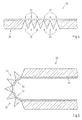
- Fig. 1 shows a first embodiment of a foldable plate according to the invention in unfolded state.
- the foldable plate 2 with a visible side 4 and a back 6 has a base plate 8 and a layer 10 arranged on the base plate.
- the layer 10 is formed as a varnish layer, the varnish layer consisting of a permanently elastic varnish, for example a varnish based on elastic chloroprenes or chlorosulfonated polyethylene products.
- a groove 12 is inserted, which extends through the entire thickness of the base plate 8, so that the groove bottom is formed only by the layer 10. It is also conceivable that the groove 12 does not extend completely through the base plate 8, so that the groove base is formed by a remaining part of the base plate 8. Due to the position of the groove 12, a folding edge 14 of the foldable plate 2 is defined. The foldable plate 2 can be folded at the folding edge 14.
- Fig. 2 is the foldable plate 2 off Fig. 1 shown after it has been folded at the folding edge 14 so that the separated by the folding edge 14 areas of the plate with their respective layer 10 abut each other.
- the foldable plate 2 has a much smaller spatial dimension and can be advantageously packaged in a smaller package.
- Fig. 3 shows a foldable plate in unfolded state.
- the foldable plate 16 differs from the foldable plate 2 Fig. 1 in that the layer 10 has, in addition to the lacquer layer 18, an additional decorative layer 20 applied to the lacquer layer 18.
- the groove 22 is V-shaped. This is advantageous, since such an overstretching of the foldable plate 16 on the groove 22 is prevented.
- the decorative layer 20 may have, for example, a color and / or a structure by which the visual appearance of the visible side 24 of the foldable plate 16 is determined. This may in particular be a layer whose composition and structure do not allow the sole use as a hinge element.
- Fig. 4 shows a second embodiment of a foldable plate according to the invention in unfolded state.
- the foldable plate 26 has on its rear side 28 a plurality of juxtaposed grooves 30. These grooves 30 are preferably parallel to each other.
- the grooves 30 are V-shaped, but could also have a 1-shape, another shape or even different shapes.
- the distances between two adjacent grooves 30 may be as in FIG Fig. 4 the same or different in size.
- the foldable plate 26 is in Fig. 5 shown folded together.
- the entire folding angle for example, a in Fig. 5 illustrated folding angle of 180 °, is divided over the individual fold edges.
- the acting as a hinge element layer 34 which analogous to that in Fig.1 layer 10 shown consists of a lacquer layer, 32 is subjected to lower loads and thus higher durability in the area of the folding edges.
- foldable plate 36 shown unfolded differs from the in Fig. 1 shown foldable plate 2 characterized in that the layer 10 a between the base plate 38 and the lacquer layer 40th arranged additional intermediate layer 42 has. Furthermore, the groove 44 is configured V-shaped.
- the intermediate layer 42 may, for example, have a primer film and / or a color corresponding to the intended appearance of the visible side. Furthermore, the intermediate layer 42 may consist of a compressed nonwoven. It can be formed as a continuous closed layer or as a non-continuous closed layer, for example with a net-like structure or a fabric structure.
- the intermediate layer 42 may further be glued, pressed or otherwise connected to the base plate 38.
- Fig. 7 shows a first embodiment of an arrangement for packaging a furniture piece kit.
- the assembly 46 includes a packaging material 50 and a furniture assembly 48.
- the furniture assembly 48 in turn comprises a foldable plate 52 and another furniture component 54, such as a cabinet side wall.
- the piece of furniture kit 48 may of course include other furniture components and other parts, such as screws, nails or building instructions.
- the packaging material 50 comprises a carton 56 and a package belt 58. Of course, other packaging materials are conceivable. In particular, the carton can be completely dispensed with and the piece of furniture kit 48 packaged only with one or more packages.
- the foldable plate 52 has a visible side 60, a backside 62 and two fold edges 64.
- the foldable plate 52 is folded around the two fold edges 64 so that the backside 62 faces outward.
- the furniture component 54 is arranged in the space enclosed by the foldable plate 52.
- the furniture component 54 is located on the visible side 60 of the foldable plate 52 at.
- the furniture assembly 48 is disposed in the carton 56 such that the back 62 of the foldable plate 52 abuts the carton 56. Alternatively, the back 62 may also rest on other furniture components or other parts of the furniture assembly 48.
- the package belt 58 extends for further fixation and stabilization of the packaging.
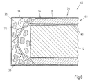
- Fig. 8 shows a second embodiment of an arrangement for packaging a furniture piece kit.
- the assembly includes a furniture assembly 68 and a packaging material 70.
- the furniture assembly 68 includes one to the in Fig. 5 shown foldable plate similar foldable plate 26 and a furniture component 72.
- the foldable plate 26 is analogous to in Fig. 7 shown folded around the folding edges 30 so that the foldable plate 26, the furniture component 72 at least partially surrounds.
- the rear side 74 of the foldable plate 26 is surrounded by the packaging material 70 consisting of a cardboard 76.
- the packaging material 70 may further include packaging fillers, such as so-called peanuts 78, which are interspersed between the Furniture kit 68 and the carton 76 can be arranged.
- the foldable plate 68 is advantageous for the arrangement, since a plurality of folding edges 30 creates a larger intermediate space for arranging the furniture component 72 surrounded by the visible side 80 of the foldable plate 26.
Landscapes
- Laminated Bodies (AREA)
Description
- Die Erfindung betrifft eine faltbare Platte mit einer Sichtseite und einer Rückseite, mit einer Grundplatte, mit einer auf der Grundplatte angeordneten Schicht und mit mindestens einer auf der Rückseite ausgebildeten Nut, wobei die Schicht auf der Sichtseite der Platte angeordnet ist, wobei die Schicht so ausgebildet ist, dass sie im Bereich der Nut eine Scharnierfunktion aufweist und wobei die Platte entlang der Nut faltbar ist
- Faltbare Platten werden insbesondere als Bestandteil von Möbelbausätzen eingesetzt, wobei sowohl Korpusteile als auch Möbelrückwände aus faltbaren Platten bestehen können. Der Vorteil der Faltbarkeit liegt darin, dass die Platten im gefalteten Zustand eine geringere Dimension aufweisen und somit in kleinere Verpackungen verpackt werden können. Zum Verpacken eines Möbelbausatzes werden die faltbaren Platten üblicherweise vollständig zusammen gefaltet, ggf. auf oder unter weiteren Möbelbauteilen angeordnet und mit einem Kartonmaterial verpackt. Die Platten weisen üblicher Weise eine Faltung auf, jedoch sind auch Faltplatten bekannt, die an zwei oder mehr Stellen gefaltet werden können.
- Aus dem Stand der Technik sind faltbare Platten bekannt, die aus zwei nebeneinander liegenden Plattenteilen bestehen, die auf der Sichtseite durch eine PVC-Schicht verbunden sind, welche im Anlagebereich der Plattenteile eine Scharnierfunktion aufweist. Diese Platten haben den Nachteil, dass sie ökologisch bedenklich sind und Anforderungen des Brandschutzes oder der Schadstoffemission durch Ausgasungen des PVCs und chemische Umwandlung des PVC beim Verbrennen nur schlecht oder unzureichend erfüllen. Weiterhin weisen PVC-Schichten eine für Möbeloberflächen ungeeignete, unerwünschte oder unbefriedigende Oberflächenstruktur auf, so dass der optische oder haptische Eindruck des Möbelteils beeinträchtigt werden kann. Aus diesen Gründen ist insbesondere die Möbelindustrie von der Verwendung derartiger faltbarer Platten abgekommen und hat vorzugsweise faltbare Platten verwendet, deren Scharnierfunktion durch einen Kleber oder durch ein Klebeband auf der Sichtseite, der Rückseite oder zwischen den Plattenteilen übernommen wird. So offenbart beispielsweise die
DE 20 2005 018 809 U1 eine faltbare Platte mit zwei voneinander getrennten Plattenteilen, die auf der Rückseite durch ein aus einem Kleber bestehendes Scharnierelement zusammengehalten werden. - Diese und vergleichbare Platten aus dem Stand der Technik haben den Nachteil, dass die Faltkante im auseinandergefalteten Zustand sichtbar bleibt und der optische Eindruck der Platte beeinträchtigt wird.
- Gattungsgemäße faltbare Platten sind sowohl aus der
JP 53064289 A US 5,413,834 bekannt. - Die
JP 53064289 A - Gemäß der
US 5,413, 834 besteht die auf der Grundplatte angeordnete Schicht aus einem gesättigtem Papier. - Der vorliegenden Erfindung liegt somit die Aufgabe zugrunde, eine faltbare Platte zur Verfügung zu stellen, welche die oben genannten Nachteile der faltbaren Platten aus dem Stand der Technik vermeidet und welche besonders einfach und kostengünstig herzustellen ist.
- Die Aufgabe wird erfindungsgemäß durch eine faltbare Platte mit den Merkmalen des Anspruchs 1 gelöst. Weitere vorteilhafte Ausgestaltungen sind in den Unteransprüchen angegeben.
- Dadurch, dass die Schicht aus einer Lackschicht besteht, die aus einem dauerhaft elastischen Lack besteht, wird erreicht, dass die faltbare Platte sowohl eine große Haltbarkeit und Steifigkeit als auch eine hohe ökologische Verträglichkeit und eine optisch und haptisch hochwertige Sichtseite aufweist, die insbesondere auch nicht durch eine sichtbare Faltkante beeinträchtigt wird. Die Erfindung überwindet dabei das technische Vorurteil, dass es eines Klebers, eines Klebebandes oder gar einer PVC-Schicht als Scharnierelement für eine faltbare Platte bedarf. Es hat sich herausgestellt, dass die aus einem elastischen Lack bestehende Schicht geeignet ist, sowohl beim Zusammen- und Auseinanderfalten der Platte eine Scharnierfunktion zu übernehmen als auch der auseinandergefalteten Platte eine hinreichende Steifigkeit zu verleihen. Unter einem Lack, aus dem die Lackschicht hergestellt wird, wird dabei jede Form von Beschichtungsmaterial verstanden, das in flüssigem oder pulverförmigem Zustand auf die Platte aufgebracht werden kann.
- Die auf der Rückseite der Platte angeordnete Nut reicht dabei bevorzugt durch die gesamte Grundplattenstärke, so dass der Nutgrund ausschließlich durch die Schicht bzw. durch die Lackschicht gebildet wird. Alternativ ist auch denkbar, dass die Nut nicht durch die gesamte Grundplatte reicht. Die Nut kann I-förmig, V-förmig oder in einer anderen Weise ausgebildet sein. Die Grundplatte besteht bevorzugt aus einem Holz oder einem Holzwerkstoff. Beispielsweise kann eine Span- oder Faserplatte oder eine Mehrschichtplatte mit Span- und/oder Faseranteilen verwendet werden.
- Eine vorteilhafte Ausgestaltung der faltbaren Platte besteht darin, dass in der Grundplatte mehrere nebeneinander angeordnete Nuten ausgebildet sind. Dadurch wird erreicht, dass der Gesamtwinkel, um den die faltbare Platte gefaltet wird auf mehrere Faltkanten verteilt wird, so dass der Faltwinkel an jeder einzelnen Nut bzw. Faltkante geringer ist als der Gesamtwinkel und die mechanische Beanspruchung der als Scharnierelement wirkenden Schicht in diesem Bereich reduziert wird. Somit ist es möglich, die Schicht dünner auszubilden bzw. eine höhere Haltbarkeit der Schicht zu erreichen und ein häufigeres Zusammen- und Auseinanderfalten der Platte zu ermöglichen.
- Denkbar ist es auf der Lackschicht zusätzlich eine Dekorschicht anzuordnen. Durch diese Ausgestaltung wird erreicht, dass die Beschaffenheit der Sichtseite der faltbaren Platte frei gewählt werden kann. So ist es zum Beispiel möglich, für die als Scharnierelement wirkende Schicht einen elastischen Lack zu verwenden, für die Dekorschicht jedoch einen anderen, dekorativen Lack. Insbesondere kann eine sehr dünne Lackschicht oder eine Lackschicht mit einer strukturierten Oberfläche verwendet werden, die für sich genommen nicht als Scharnierelement geeignet wäre. Es ist natürlich auch möglich, die als Scharnierelement wirkende Lackschicht direkt als Dekorschicht auszubilden, so dass auf das Aufbringen einer zusätzlichen Schicht verzichtet und die faltbare Platte kostengünstiger, einfacher und schneller hergestellt werden kann. Weiterhin ist denkbar, dass auf die Lackschicht mehr als eine weitere Schicht aufgebracht wird, um beispielsweise einen bestimmten dekorativen Effekt zu erreichen.
- In einer vorteilhaften Ausgestaltung der faltbaren Platte weist die die Sichtseite bildende Schicht eine Verstärkung bzw. eine Armierung auf. Diese Armierung kann beispielsweise in der Lackschicht oder in einer weiteren Schicht angeordnet sein. Für die Armierung einer solchen Schicht eignen sich beispielsweise Fasern, die in die Schicht eingebettet werden. Der Vorteil dieser Ausgestaltung liegt darin, dass die Stabilität der Schicht erhöht und somit die Scharnierfunktion verbessert wird.
- Erfindungsgemäß besteht die Lackschicht im Wesentlichen aus einem Lack, der eine Glasübergangstemperatur im Bereich üblicher Raumtemperaturen aufweist. Eine weitere vorteilhafte Ausgestaltung der faltbaren Platte besteht darin, dass die Lackschicht eine Glasübergangstemperatur zwischen 15 °C und 30 °C aufweist. Unter einer Glasübergangstemperatur wird in diesem Zusammenhang diejenige Temperatur verstanden, bei der die Kurve des logarithmischen Elastizitätsmoduls einen Wendepunkt aufweist. Der Bereich um die Glasübergangstemperatur ist somit durch eine starke Temperaturabhängigkeit des logarithmischen Elastizitätsmoduls gekennzeichnet. Die Verwendung eines Lacks mit einer Glasübergangstemperatur im Bereich der Raumtemperatur hat den Vorteil, dass der Elastizitätsmodul des Lackes einen vorteilhaften Mittelwert einnimmt, so dass der Lack sowohl eine ausreichende Biegefähigkeit als auch eine ausreichende Zähigkeit aufweist. Dadurch kann die Platte leicht gefaltet werden und weist im auseinandergefalteten Zustand eine große Steifigkeit auf. Weiterhin kann bereits durch eine leichte Erwärmung des Lacks im Bereich der Nut der Elastizitätsmodul stark verringert werden, so dass das Falten der Platte weiter vereinfacht wird. Beim Abkühlen der auseinandergefalteten Platte an der Raumluft nimmt der Elastizitätsmodul wieder zu, so dass die Steifigkeit der Platte wieder erhöht wird.
- In einer vorteilhaften Ausgestaltung weist die Lackschicht einen Tiefungswert nach Erichsen von mindestens 5 mm, bevorzugt 8 mm und insbesondere mindestens 10 mm auf und/oder besteht den Dornbiegetest nach EN ISO 6860 bei einem Biegedorndurchmesser von höchstens 10 mm, bevorzugt höchstens 6 mm, insbesondere höchstens 4 mm. Unter dem Tiefungswert nach Erichsen wird die Tiefe verstanden, bis zu der eine gehärtete, polierte Stahlkugel mit einem Durchmesser von 20 mm mit einer gleichmäßigen Vorschubgeschwindigkeit von etwa 0,2 mm/s mittels eines Stößels in die Lackschicht gedrückt werden kann, bevor sich an der Oberfläche der Lackschicht erste Risse bilden. Die Verwendung einer solchen Lackschicht ist vorteilhaft, da so eine große Haltbarkeit der Lackschicht erreicht wird und ein häufiges Zusammen- oder Auseinanderfalten der Platte ermöglicht wird.
- Eine weitere vorteilhafte Ausgestaltung der faltbaren Platte ist dadurch gegeben, dass die Lackschicht auf Lösungen und Dispersionen elastischer Chloroprene und/oder chlorsulfonierter Polyethylenprodukte basiert. Solche Lackschichten zeichnen sich durch eine besonders hohe und dauerhafte Elastizität aus.
- Eine weitere vorteilhafte Ausgestaltung der faltbaren Platte ist dadurch gegeben, dass die Lackschicht auf Lösungen und Dispersionen von Silikonharzen und/oder elastisch eingestellten Polyurethanen basiert. Auch diese Lackschichten zeichnen sich durch eine besonders hohe und dauerhafte Elastizität aus.
- Eine weitere vorteilhafte Ausgestaltung der faltbaren Platte besteht darin, dass die Lackschicht eine Epoxid- oder Acrylkomponente oder Mischungen daraus aufweist. Solche Lackschichten zeichnen sich ebenfalls durch eine besonders hohe und dauerhafte Elastizität aus.
- Eine weitere vorteilhafte Ausgestaltung der faltbaren Platte besteht darin, dass die Lackschicht mindestens teilweise aus einem Elastomer gebildet wird. Solche Lackschichten zeichnen sich durch eine besonders hohe und dauerhafte Elastizität aus.
- Weiterhin ist es denkbar, dass die Schicht eine zwischen der Lackschicht und der Sichtseite angeordnete Zwischenschicht aufweist. Unter einer Zwischenschicht wird dabei eine Schicht verstanden, die durch ihre Zusammensetzung und/oder ihre Struktur geeignet ist, die Lackschicht beim Zusammen- und Auseinanderfalten der Platte zu entlasten und teilweise oder vollständig die Scharnierfunktion der Lackschicht zu übernehmen. Grundsätzlich ist dafür jedes Flächengebilde geeignet, das mit der Platte verbunden werden kann. Eine solche Ausführung ist besonders vorteilhaft, da auf diese Weise eine sehr dünne Lackschicht oder eine Lackschicht mit einer strukturierten Oberfläche verwendet werden kann, die für sich genommen nicht als Scharnierelement geeignet wäre. Weiterhin führt die zusätzliche Schicht zu einer erhöhten Steifigkeit der faltbaren Platte im auseinander gefalteten Zustand. Besonders bevorzugt ist die Verwendung einer Zwischenschicht, die ohne weitere Vorbehandlung mit einer Lackschicht beschichtet werden kann, da auf diese Weise der Arbeitsaufwand, insbesondere die Untergrundvorbereitung wie das Schleifen und Grundieren der Plattenoberfläche entfallen, womit die Herstellungskosten reduziert werden.
- Denkbar ist es weiterhin, dass die Zwischenschicht eine Grundierfolie aufweist. Besonders vorteilhaft ist dabei die Verwendung von Grundierfolien auf der Basis von Edelzellulose. Diese können weiterhin mit einem Kunstharz imprägniert sein. Der Vorteil dieser Ausgestaltung liegt darin, dass die Lackschicht durch die Grundierfolie besser an der faltbaren Platte haftet. Weiterhin können zum Beispiel durch entsprechende Einfärbung der Grundierplatte besondere Farbgebungen der Sichtseite der faltbaren Platte erreicht werden.
- Ebenfalls denkbar ist es, dass die Zwischenschicht im Wesentlichen eine dem beabsichtigten Erscheinungsbild der Sichtseite entsprechende Farbe aufweist. Diese Ausgestaltung hat den Vorteil, dass die Lackschicht besonders dünn ausgestaltet werden kann, ohne dass das äußere Erscheinungsbild der Sichtseite durch ein Durchscheinen einer abweichenden
- Farbgebung der Zwischenschicht beeinträchtigt würde. Es ist sogar möglich, eine transparente Lackschicht zu verwenden.
- Beispielsweise ist die Zwischenschicht dabei ohne eine weitere Vorbehandlung bedruckbar. Auf die Zwischenschicht kann so ein Muster, beispielsweise eine Maserungsstruktur, aufgedruckt werden, so dass im Zusammenwirken der farbigen Zwischenschicht und des Aufdrucks das beabsichtigte optische Erscheinungsbild entsteht. Eine auf den Aufdruck aufgebrachte Lackschicht, insbesondere eine transparente Lackschicht kann das optische Erscheinungsbild ergänzen und die bedruckte Oberfläche versiegeln und so vor einer Beschädigung schützen.
- Es ist denkbar, dass die Zwischenschicht mit der Platte verpresst ist. Diese Ausgestaltung hat den Vorteil, dass durch die besonders innige Verbindung zwischen der Zwischenschicht und der Platte eine hohe Haltbarkeit der faltbaren Platte erreicht wird. Die Verpressung der Zwischenschicht mit der Platte kann direkt erfolgen, indem die Zwischenschicht unmittelbar vor dem Verpressen der Platte auf den Plattenrohling aufgebracht wird. Dies hat den Vorteil, dass die Zwischenschicht nicht nachträglich mit der Platte verbunden werden muss und führt so zu einer Vereinfachung des Herstellungsverfahrens der Platte und so zu einer Kostenreduktion. Für diese Ausgestaltung sind insbesondere Flächengebilde geeignet, die über eine den Verpressungsbedingungen entsprechende Temperatur- und Feuchtebeständigkeit verfügen.
- Weiterhin kann die Zwischenschicht eine nicht durchgehend geschlossene, insbesondere eine netzartige Struktur oder eine Gewebestruktur aufweist. Durch eine solche Struktur der Zwischenschicht wird eine hohe Elastizität bei gleichzeitiger hoher Haltbarkeit der Zwischenschicht und somit eine Verbesserung der Scharnierwirkung der Zwischenschicht erreicht. Weiterhin ist eine solche Zwischenschicht vorteilhaft bei der direkten Verpressung der Schicht mit der Platte entsprechend der vorherigen Ausgestaltung, da auf diese Weise höhere Produktionsgeschwindigkeiten erreicht werden. So kann der während des Verpressens in dem Plattenrohling entstehende und abzuführende Dampf nahezu ungehindert durch die nicht durchgehend geschlossene Schicht gelangen, so dass eine Verlängerung der Presszeit im Gegensatz zur Verpressung durchgehender Schichten vermieden wird.
- Es ist des Weiteren möglich, dass die Zwischenschicht aus einem verpressten Vlies besteht. Ein Vlies weist aufgrund seiner langen Fasern eine hohe Elastizität und Haltbarkeit auf und eignet sich damit sehr gut als Scharnierelement. Diese Ausgestaltung hat weiterhin den Vorteil, dass das Vlies bereits vor dem Pressen der Platte auf den Plattenrohling aufgebracht werden kann, so dass durch die gemeinsame Verpressung zum einen eine innige Verbindung zwischen der Platte und dem Vlies erreicht wird und zum anderen der Herstellungsprozess einfach und kostengünstig gehalten werden kann.
- Im Folgenden wird eine Anordnung zum Verpacken eines Möbelstückbausatzes, mit einem Möbelstückbausatz und mit einem Verpackungsmaterial, wobei der Möbelstückbausatz eine faltbare Platte, insbesondere eine faltbare Platte nach einer der zuvor beschriebenen Ausgestaltungen, aufweist, wobei der Möbelstückbausatz mindestens ein weiteres Möbelbauteil aufweist und wobei die faltbare Platte mindestens zwei voneinander beabstandete Nuten aufweist, wobei die faltbare Platte entlang mindestens zwei der Nuten zumindest teilweise gefaltet ist und wobei die faltbare Platte so angeordnet ist, dass die Sichtseite der faltbaren Platte in Richtung des Möbelbauteils weist und dass die Rückseite der faltbaren Platte in Richtung des Verpackungsmaterials weist, beschrieben.
- Dadurch, dass die faltbare Platte entlang von mindestens zwei der Nuten zumindest teilweise gefaltet ist und dass die faltbare Platte in einer Verpackung eines Möbelstückbausatzes so angeordnet ist, dass die Sichtseite der faltbaren Platte zur Innenseite der Verpackung weist und dass die Rückseite der faltbaren Platte zur Außenseite der Verpackung weist, wird erreicht, dass die weiteren Möbelbauteile des Möbelstückbausatzes zumindest teilweise nicht unmittelbar an der Verpackung anliegen und so vor mechanischen Beschädigung, beispielsweise durch den Transport, geschützt ist. So wird eine mechanische Krafteinwirkung auf die Verpackung durch die faltbare Platte abgeschwächt und kann nur noch in schwächerer Form auf innenliegende Möbelbauteile des Möbelstückbausatzes einwirken. Die faltbare Platte selbst ist so angeordnet, dass die empfindlichere Sichtseite nach Innen weist, so dass sie bei einer gewissen mechanischen Krafteinwirkung nicht direkt beschädigt wird.
- Weitere Merkmale und Vorteile der vorliegenden Erfindung werden in der Beschreibung einiger Ausführungsbeispiele näher erläutert, wobei auf die beigefügte Zeichnung Bezug genommen wird. In der Zeichnung zeigen
- Fig. 1
- ein erstes Ausführungsbeispiel einer erfindungsgemäßen faltbaren Platte in auseinandergefaltetem Zustand,
- Fig. 2
- das erste Ausführungsbeispiel aus
Fig. 1 in zusammengefaltetem Zustand. - Fig. 3
- eine faltbare Platte in auseinandergefaltetem Zustand,
- Fig. 4
- ein zweites Ausführungsbeispiel einer erfindungsgemäßen faltbaren Platte in auseinandergefaltetem Zustand,
- Fig. 5
- das zweite Ausführungsbeispiel aus
Fig. 4 in zusammengefaltetem Zustand. - Fig. 6
- eine faltbare Platte in auseinandergefaltetem Zustand,
- Fig. 7
- ein erstes Ausführungsbeispiel einer Anordnung zum Verpacken eines Möbelstückbausatzes und
- Fig. 8
- ein zweites Ausführungsbeispiel einer Anordnung zum Verpacken eines Möbelstückbausatzes.
-
Fig. 1 zeigt ein erstes Ausführungsbeispiel einer erfindungsgemäßen faltbaren Platte in auseinandergefaltetem Zustand. Die faltbare Platte 2 mit einer Sichtseite 4 und einer Rückseite 6 weist eine Grundplatte 8 sowie eine auf der Grundplatte angeordnete Schicht 10 aus. Die Schicht 10 ist als Lackschicht ausgebildet, wobei die Lackschicht aus einem dauerhaft elastischen Lack, beispielsweise aus einem auf elastischen Chloroprenen oder chlorsulfoniertern Polyethylenprodukten basierendem Lack, besteht. Auf der Rückseite der faltbaren Platte 2 ist eine Nut 12 eingelassen, welche durch die gesamte Stärke der Grundplatte 8 reicht, so dass der Nutgrund nur von der Schicht 10 gebildet wird. Es ist auch denkbar, dass die Nut 12 nicht vollständig durch die Grundplatte 8 reicht, so dass der Nutgrund durch einen verbleibenden Teil der Grundplatte 8 gebildet wird. Durch die Lage der Nut 12 wird eine Faltkante 14 der faltbaren Platte 2 definiert. Die faltbare Platte 2 kann an der Faltkante 14 gefaltet werden. - In
Fig. 2 ist die faltbare Platte 2 ausFig. 1 gezeigt, nachdem sie an der Faltkante 14 so gefaltet wurde, dass die durch die Faltkante 14 getrennten Bereiche der Platte mit ihrer jeweiligen Schicht 10 aneinander anliegen. In diesem zusammengefalteten Zustand weist die faltbare Platte 2 eine wesentlich geringere räumliche Dimension auf und kann vorteilhaft in einer kleineren Verpackung verpackt werden. -
Fig. 3 zeigt eine faltbare Platte in auseinandergefaltetem Zustand. Die faltbare Platte 16 unterscheidet sich von der faltbaren Platte 2 ausFig. 1 dadurch, dass die Schicht 10 eine neben der Lackschicht 18 eine auf der Lackschicht 18 aufgebrachte zusätzliche Dekorschicht 20 aufweist. Weiterhin ist die Nut 22 V-förmig ausgebildet. Dies ist vorteilhaft, da so ein Überdehnen der faltbaren Platte 16 an der Nut 22 verhindert wird. Die Dekorschicht 20 kann beispielsweise eine Farbe und/oder eine Struktur aufweisen, durch die das optische Erscheinungsbild der Sichtseite 24 der faltbaren Platte 16 bestimmt wird. Dabei kann es sich insbesondere um eine Schicht handeln, deren Zusammensetzung und Struktur den alleinigen Einsatz als Scharnierelement nicht erlauben. -
Fig. 4 zeigt ein zweites Ausführungsbeispiel einer erfindungsgemäßen faltbaren Platte in auseinandergefaltetem Zustand. Die faltbare Platte 26 weist auf ihrer Rückseite 28 mehrere nebeneinander liegende Nuten 30 auf. Diese Nuten 30 liegen in bevorzugter Weise parallel zueinander. Die Nuten 30 sind V-förmig ausgestaltet, könnten aber auch eine 1-Form, eine andere Form oder sogar verschiedene Formen aufweisen. Die Abstände zwischen zwei benachbarten Nuten 30 können wie inFig. 4 gleich oder aber auch unterschiedlich groß sein. Durch die Mehrzahl der Nuten wird eine entsprechende Zahl von Faltkanten 32 definiert. - Die faltbare Platte 26 ist in
Fig. 5 in zusammen gefaltetem Zustand dargestellt. Durch die Mehrzahl der Nuten 30 und die dadurch bedingte Mehrzahl der Faltkanten 32 wird erreicht, dass der gesamte Faltungswinkel, beispielsweise ein inFig. 5 dargestellter Faltungswinkel von 180°, auf die einzelnen Faltkanten aufgeteilt wird. So liegt bei ungefährer Gleichverteilung des Winkels bei der inFig. 5 gezeigten zusammen gefalteten faltbaren Platte 26 an jeder Faltkante 32 ein Faltwinkel von etwa 30° vor. Die als Scharnierelement wirkende Schicht 34, die analog zu der inFig.1 gezeigten Schicht 10 aus einer Lackschicht besteht, ist so im Bereich der Faltkanten 32 geringeren Belastungen ausgesetzt und damit von höherer Haltbarkeit. - Die in
Fig. 6 gezeigte faltbare Platte 36 in auseinandergefaltetem Zustand unterscheidet sich von der inFig. 1 gezeigten faltbaren Platte 2 dadurch, dass die Schicht 10 eine zwischen der Grundplatte 38 und der Lackschicht 40 angeordnete zusätzliche Zwischenschicht 42 aufweist. Weiterhin ist die Nut 44 V-förmig ausgestaltet. Die Zwischenschicht 42 kann beispielsweise eine Grundierfolie und/oder eine mit dem beabsichtigten Erscheinungsbild der Sichtseite entsprechende Farbe aufweisen. Weiterhin kann die Zwischenschicht 42 aus einem verpressten Vlies bestehen. Sie kann als durchgehend geschlossene Schicht oder als nicht durchgehend geschlossene Schicht, beispielsweise mit einer netzartigen Struktur oder einer Gewebestruktur, ausgebildet sein. Die Zwischenschicht 42 kann weiterhin mit der Grundplatte 38 verklebt, verpresst oder auf eine andere Weise verbunden sein. -
Fig. 7 zeigt ein erstes Ausführungsbeispiel einer Anordnung zum Verpacken eines Möbelstückbausatzes. Die Anordnung 46 umfasst ein Verpackungsmaterial 50 und einen Möbelstückbausatz 48. Der Möbelstückbausatz 48 umfasst wiederum eine faltbare Platte 52 und ein weiteres Möbelbauteil 54, beispielsweise eine Schrankseitenwand. Der Möbelstückbausatz 48 kann natürlich noch weitere Möbelbauteile und andere Teile, wie Schrauben, Nägel oder Bauanleitungen umfassen. Das Verpackungsmaterial 50 umfasst einen Karton 56 und ein Paketband 58. Natürlich sind auch andere Verpackungsmaterialien denkbar. Insbesondere kann auf den Karton vollständig verzichtet werden und der Möbelstückbausatz 48 nur mit einem oder mehreren Paketbändern verpackt sein. Die faltbare Platte 52 weist eine Sichtseite 60, eine Rückseite 62 und zwei Faltkanten 64 auf. Die faltbare Platte 52 ist um die zwei Faltkanten 64 so gefaltet, dass die Rückseite 62 nach außen weist. In dem von der faltbaren Platte 52 eingeschlossenen Zwischenraum ist das Möbelbauteil 54 angeordnet. Dabei liegt das Möbelbauteil 54 an der Sichtseite 60 der faltbaren Platte 52 an. Der Möbelstückbausatz 48 ist so in dem Karton 56 angeordnet, dass die Rückseite 62 der faltbaren Platte 52 an dem Karton 56 anliegt. Alternativ kann die Rückseite 62 auch an weiteren Möbelbauteilen oder anderen Teilen des Möbelstückbausatzes 48 anliegen. Um den Karton 56 verläuft das Paketband 58 zur weiteren Fixierung und Stabilisierung der Verpackung. Durch die teilweise das Möbelbauteil 54 umgebende faltbare Platte 52 wird erreicht, dass die Verpackungsgröße verkleinert wird und dass das Möbelbauteil 54 durch die faltbare Platte 52 zusätzlich vor mechanischen Beschädigungen beispielsweise durch den Transport geschützt ist. Die empfindlichere Sichtseite 60 der faltbaren Platte 52 ist dabei dadurch geschützt, dass sie nach innen weist und zumindest teilweise an dem Möbelbauteil 54 anliegt. -
Fig. 8 zeigt ein zweites Ausführungsbeispiel einer Anordnung zum Verpacken eines Möbelstückbausatzes. Die Anordnung umfasst einen Möbelstückbausatz 68 und ein Verpackungsmaterial 70. Der Möbelstückbausatz 68 umfasst eine zu der inFig. 5 gezeigten faltbaren Platte gleichartige faltbare Platte 26 sowie ein Möbelbauteil 72. Die faltbare Platte 26 ist analog zum inFig. 7 gezeigten ersten Ausführungsbeispiel so um die Faltkanten 30 gefaltet, dass die faltbare Platte 26 das Möbelbauteil 72 zumindest teilweise umgibt. Die Rückseite 74 der faltbaren Platte 26 wird von dem aus einem Karton 76 bestehenden Verpackungsmaterial 70 umgeben. Zur weiteren Stabilisierung der Verpackung und zum weiteren Schutz des Möbelstückbausatzes 68 kann das Verpackungsmaterial 70 weiterhin Verpackungs-Füllstoffe, wie zum Beispiel sogenannte Peanuts 78 umfassen, die in den Zwischenräumen zwischen dem Möbelstückbausatz 68 und dem Karton 76 angeordnet werden können. Die faltbare Platte 68 ist vorteilhaft für die Anordnung, da durch die Mehrzahl der Faltkanten 30 ein von der Sichtseite 80 der faltbaren Platte 26 umgebener größerer Zwischenraum zur Anordnung des Möbelbauteils 72 entsteht.
Claims (7)
- Faltbare Platte (2, 16, 26, 36, 52),- mit einer Sichtseite (4, 24, 60, 80) und einer Rückseite (6, 62, 74),- mit einer Grundplatte (8, 38),- mit einer auf der Grundplatte (8) angeordneten und die Sichtseite (4, 24, 60, 80) bildenden Schicht (10) und- mit mindestens einer in der Grundplatte (8, 38) ausgebildeten Nut (12, 22, 30, 44),- wobei die Schicht (10) so ausgebildet ist, dass sie im Bereich der Nut (12) eine Scharnierfunktion aufweistund- wobei die Platte entlang der Nut (12) faltbar ist, dadurch gekennzeichnet,- dass die Schicht (10) aus einer Lackschicht (18, 40) besteht, die aus einem dauerhaft elastischen Lack besteht.
- Faltbare Platte nach Anspruch 1,
dadurch gekennzeichnet,
dass in der Grundseite (8, 38) mehrere nebeneinander angeordnete Nuten (12, 22, 30, 44) ausgebildet sind. - Faltbare Platte nach einem der Ansprüche 1 oder 2,
dadurch gekennzeichnet,
dass die Lackschicht (18, 40) eine Glasübergangstemperatur zwischen 15 °C und 30 °C aufweist. - Faltbare Platte nach einem der Ansprüche 1 bis 3,
dadurch gekennzeichnet,
dass die Lackschicht (18, 40) auf Lösungen und Dispersionen elastischer Chloroprene und/oder chlorsulfonierter Polyethylenprodukte basiert. - Faltbare Platte nach einem der Ansprüche 1 bis 4,
dadurch gekennzeichnet,
dass die Lackschicht (18, 40) auf Lösungen und Dispersionen von Silikonharzen und/oder elastisch eingestellten Polyurethanen basiert. - Faltbare Platte nach einem der Ansprüche 1 bis 5,
dadurch gekennzeichnet,
dass die Lackschicht (18, 40) eine Epoxid- oder Acrylkomponente oder Mischungen daraus aufweist. - Faltbare Platte nach einem der Ansprüche 1 bis 6,
dadurch gekennzeichnet,
dass die Lackschicht (18, 40) mindestens teilweise aus einem Elastomer gebildet wird.
Priority Applications (1)
| Application Number | Priority Date | Filing Date | Title |
|---|---|---|---|
| PL09170302T PL2177130T3 (pl) | 2008-10-14 | 2009-09-15 | Płyta składana |
Applications Claiming Priority (1)
| Application Number | Priority Date | Filing Date | Title |
|---|---|---|---|
| DE102008051213A DE102008051213A1 (de) | 2008-10-14 | 2008-10-14 | Faltbare Platte |
Publications (3)
| Publication Number | Publication Date |
|---|---|
| EP2177130A2 EP2177130A2 (de) | 2010-04-21 |
| EP2177130A3 EP2177130A3 (de) | 2012-07-25 |
| EP2177130B1 true EP2177130B1 (de) | 2016-11-02 |
Family
ID=41581961
Family Applications (1)
| Application Number | Title | Priority Date | Filing Date |
|---|---|---|---|
| EP09170302.5A Active EP2177130B1 (de) | 2008-10-14 | 2009-09-15 | Faltbare Platte |
Country Status (5)
| Country | Link |
|---|---|
| EP (1) | EP2177130B1 (de) |
| DE (1) | DE102008051213A1 (de) |
| DK (1) | DK2177130T3 (de) |
| HU (1) | HUE029792T2 (de) |
| PL (1) | PL2177130T3 (de) |
Families Citing this family (3)
| Publication number | Priority date | Publication date | Assignee | Title |
|---|---|---|---|---|
| DE102011113389A1 (de) * | 2011-09-16 | 2013-03-21 | Fritz Egger Gmbh & Co. Og | Faltbare Platte |
| DE102014001915A1 (de) | 2013-02-28 | 2014-08-28 | Schattdecor Ag | Strukturelement für den Möbelbau ud Innenausbau mit einer Dekorschicht sowie die Verwendung einer Verbundpapier-Dekorfolie als derartige Dekorschicht |
| FR3025989B1 (fr) * | 2014-09-18 | 2017-02-24 | Alsapan | Fond pliant pour equiper un meuble |
Family Cites Families (7)
| Publication number | Priority date | Publication date | Assignee | Title |
|---|---|---|---|---|
| JPS5364289A (en) | 1976-11-20 | 1978-06-08 | Eidai Co Ltd | Decorative sheet |
| EP0119699B1 (de) * | 1983-02-21 | 1988-06-22 | Imperial Chemical Industries Plc | Wässriges Latexcopolymerisat enthaltende Zusammensetzung |
| US5413834A (en) | 1992-03-31 | 1995-05-09 | Specialty Paperboard/Endura, Inc. | Miter-foldable saturated paper-based overlay system and method for fabricating the same |
| WO2002079571A1 (de) * | 2001-03-30 | 2002-10-10 | Kronospan Technical Company Ltd. | Papier für die herstellung von paneelen sowie verfahren für die papierherstellung |
| EP1523908A1 (de) * | 2003-10-14 | 2005-04-20 | Composad s.r.l. | Rückwand für Anbaumöbel |
| DE10354460B3 (de) * | 2003-11-21 | 2004-10-21 | Fortuna Medien Gmbh | Faltbare Platten |
| DE202005018809U1 (de) | 2005-11-30 | 2007-04-05 | Fritz Egger Gmbh & Co. | Faltbare Platte |
-
2008
- 2008-10-14 DE DE102008051213A patent/DE102008051213A1/de not_active Ceased
-
2009
- 2009-09-15 PL PL09170302T patent/PL2177130T3/pl unknown
- 2009-09-15 HU HUE09170302A patent/HUE029792T2/en unknown
- 2009-09-15 EP EP09170302.5A patent/EP2177130B1/de active Active
- 2009-09-15 DK DK09170302.5T patent/DK2177130T3/en active
Non-Patent Citations (1)
| Title |
|---|
| THOMAS BROCK, MICHAEL GROTEKLAES, PETER MISCHKE: "Lehrbuch der Lacktechnologie, 2. Auflage", ULRICH ZORLL, VINCENTZ NETWORK, ISBN: 3878705697, article "2.1.1.12 Temperaturabhängigkeit des Polymerverhaltens - Glasübergangstemperatur", pages: 42 - 45 * |
Also Published As
| Publication number | Publication date |
|---|---|
| PL2177130T3 (pl) | 2017-06-30 |
| EP2177130A3 (de) | 2012-07-25 |
| DK2177130T3 (en) | 2016-12-12 |
| EP2177130A2 (de) | 2010-04-21 |
| DE102008051213A1 (de) | 2010-04-15 |
| HUE029792T2 (en) | 2017-04-28 |
Similar Documents
| Publication | Publication Date | Title |
|---|---|---|
| EP1559850B1 (de) | Paneel, insbesondere Fussbodenpaneel | |
| EP1985464B1 (de) | Bauplatte, insbesondere Fußbodenpaneel, und Verfahren zu deren Herstellung | |
| EP2147773B1 (de) | Beschichtete dekorative Trägerplatte (DPL) mit Biegekante und Verfahren zur Herstellung der beschichteten Trägerplatte | |
| WO1999009274A2 (de) | Belagelement für gebäudeoberflächen oder dergleichen sowie verfahren seiner herstellung | |
| DE102006054634B4 (de) | Leichtbau-Verbundplatte | |
| EP3736095A2 (de) | Plattenförmiger werkstoff und verfahren zu dessen herstellung | |
| DE102008027235B4 (de) | Werkstoffplatte | |
| DE102014010747B4 (de) | Verfahren zur Herstellung von Bauplatten, insbesondere Fußbodenpaneelen | |
| EP2177130B1 (de) | Faltbare Platte | |
| EP1792551B1 (de) | Faltbare Platte | |
| DE202008004011U1 (de) | Mehrschichtige flexible Werkstoffplatte | |
| EP4013582A1 (de) | Mehrschichtiger holzkompositblock, mehrschichtiges holzfurnier sowie verfahren zur herstellung derselben | |
| DE102008030572A1 (de) | Furniersystem | |
| EP2146841B1 (de) | Leichtbauplatte | |
| EP0524403A1 (de) | Mehrschichtmaterialstruktur | |
| EP1915252B1 (de) | Dekorative holzwerkstoffplatte und verfahren zu ihrer herstellung | |
| EP1217143B1 (de) | Trittstufe für Treppen | |
| DE102010016048B4 (de) | Bauplatte mit Beschichtung und Verfahren zum Beschichten von Bauplatten | |
| DE102017003640A1 (de) | Belagselement für einen Belag sowie Verfahren zur Herstellung eines solchen Belagselements | |
| DE19754143A1 (de) | Platte für den Innenausbau in Fahrzeugen und Verfahren zu deren Herstellung | |
| DE102010011148B4 (de) | Leichtbauplatte sowie Verfahren zu deren Herstellung | |
| DE202009004235U1 (de) | Leichtbauplatte | |
| EP3800049B1 (de) | Verfahren zur herstellung eines folienverbunds, folienverbund zur verpackung von produkten sowie verpackung | |
| WO1999004965A1 (de) | Plattenförmiger werkstoff | |
| DE202006010444U1 (de) | Auskleidungsteil für den Fußraum eines Kraftfahrzeugs |
Legal Events
| Date | Code | Title | Description |
|---|---|---|---|
| PUAI | Public reference made under article 153(3) epc to a published international application that has entered the european phase |
Free format text: ORIGINAL CODE: 0009012 |
|
| AK | Designated contracting states |
Kind code of ref document: A2 Designated state(s): AT BE BG CH CY CZ DE DK EE ES FI FR GB GR HR HU IE IS IT LI LT LU LV MC MK MT NL NO PL PT RO SE SI SK SM TR |
|
| RAP1 | Party data changed (applicant data changed or rights of an application transferred) |
Owner name: FRITZ EGGER GMBH & CO. OG |
|
| RIC1 | Information provided on ipc code assigned before grant |
Ipc: A47B 96/20 20060101AFI20120302BHEP |
|
| PUAL | Search report despatched |
Free format text: ORIGINAL CODE: 0009013 |
|
| AK | Designated contracting states |
Kind code of ref document: A3 Designated state(s): AT BE BG CH CY CZ DE DK EE ES FI FR GB GR HR HU IE IS IT LI LT LU LV MC MK MT NL NO PL PT RO SE SI SK SM TR |
|
| RIC1 | Information provided on ipc code assigned before grant |
Ipc: A47B 96/20 20060101AFI20120621BHEP |
|
| 17P | Request for examination filed |
Effective date: 20121220 |
|
| 17Q | First examination report despatched |
Effective date: 20130205 |
|
| RAP1 | Party data changed (applicant data changed or rights of an application transferred) |
Owner name: FRITZ EGGER GMBH & CO. OG |
|
| GRAP | Despatch of communication of intention to grant a patent |
Free format text: ORIGINAL CODE: EPIDOSNIGR1 |
|
| INTG | Intention to grant announced |
Effective date: 20160428 |
|
| GRAS | Grant fee paid |
Free format text: ORIGINAL CODE: EPIDOSNIGR3 |
|
| RIN1 | Information on inventor provided before grant (corrected) |
Inventor name: SCHNEIDER, GEROLD |
|
| GRAA | (expected) grant |
Free format text: ORIGINAL CODE: 0009210 |
|
| AK | Designated contracting states |
Kind code of ref document: B1 Designated state(s): AT BE BG CH CY CZ DE DK EE ES FI FR GB GR HR HU IE IS IT LI LT LU LV MC MK MT NL NO PL PT RO SE SI SK SM TR |
|
| REG | Reference to a national code |
Ref country code: GB Ref legal event code: FG4D Free format text: NOT ENGLISH |
|
| REG | Reference to a national code |
Ref country code: AT Ref legal event code: REF Ref document number: 840912 Country of ref document: AT Kind code of ref document: T Effective date: 20161115 Ref country code: CH Ref legal event code: EP Ref country code: CH Ref legal event code: NV Representative=s name: SCHMAUDER AND PARTNER AG PATENT- UND MARKENANW, CH |
|
| REG | Reference to a national code |
Ref country code: RO Ref legal event code: EPE |
|
| REG | Reference to a national code |
Ref country code: IE Ref legal event code: FG4D Free format text: LANGUAGE OF EP DOCUMENT: GERMAN |
|
| REG | Reference to a national code |
Ref country code: DK Ref legal event code: T3 Effective date: 20161209 |
|
| REG | Reference to a national code |
Ref country code: SE Ref legal event code: TRGR |
|
| REG | Reference to a national code |
Ref country code: DE Ref legal event code: R096 Ref document number: 502009013294 Country of ref document: DE |
|
| PG25 | Lapsed in a contracting state [announced via postgrant information from national office to epo] |
Ref country code: LV Free format text: LAPSE BECAUSE OF FAILURE TO SUBMIT A TRANSLATION OF THE DESCRIPTION OR TO PAY THE FEE WITHIN THE PRESCRIBED TIME-LIMIT Effective date: 20161102 |
|
| REG | Reference to a national code |
Ref country code: NL Ref legal event code: MP Effective date: 20161102 |
|
| REG | Reference to a national code |
Ref country code: LT Ref legal event code: MG4D |
|
| PG25 | Lapsed in a contracting state [announced via postgrant information from national office to epo] |
Ref country code: LT Free format text: LAPSE BECAUSE OF FAILURE TO SUBMIT A TRANSLATION OF THE DESCRIPTION OR TO PAY THE FEE WITHIN THE PRESCRIBED TIME-LIMIT Effective date: 20161102 Ref country code: NL Free format text: LAPSE BECAUSE OF FAILURE TO SUBMIT A TRANSLATION OF THE DESCRIPTION OR TO PAY THE FEE WITHIN THE PRESCRIBED TIME-LIMIT Effective date: 20161102 Ref country code: GR Free format text: LAPSE BECAUSE OF FAILURE TO SUBMIT A TRANSLATION OF THE DESCRIPTION OR TO PAY THE FEE WITHIN THE PRESCRIBED TIME-LIMIT Effective date: 20170203 Ref country code: NO Free format text: LAPSE BECAUSE OF FAILURE TO SUBMIT A TRANSLATION OF THE DESCRIPTION OR TO PAY THE FEE WITHIN THE PRESCRIBED TIME-LIMIT Effective date: 20170202 |
|
| REG | Reference to a national code |
Ref country code: HU Ref legal event code: AG4A Ref document number: E029792 Country of ref document: HU |
|
| PG25 | Lapsed in a contracting state [announced via postgrant information from national office to epo] |
Ref country code: PT Free format text: LAPSE BECAUSE OF FAILURE TO SUBMIT A TRANSLATION OF THE DESCRIPTION OR TO PAY THE FEE WITHIN THE PRESCRIBED TIME-LIMIT Effective date: 20170302 Ref country code: HR Free format text: LAPSE BECAUSE OF FAILURE TO SUBMIT A TRANSLATION OF THE DESCRIPTION OR TO PAY THE FEE WITHIN THE PRESCRIBED TIME-LIMIT Effective date: 20161102 Ref country code: ES Free format text: LAPSE BECAUSE OF FAILURE TO SUBMIT A TRANSLATION OF THE DESCRIPTION OR TO PAY THE FEE WITHIN THE PRESCRIBED TIME-LIMIT Effective date: 20161102 Ref country code: IS Free format text: LAPSE BECAUSE OF FAILURE TO SUBMIT A TRANSLATION OF THE DESCRIPTION OR TO PAY THE FEE WITHIN THE PRESCRIBED TIME-LIMIT Effective date: 20170302 |
|
| REG | Reference to a national code |
Ref country code: SK Ref legal event code: T3 Ref document number: E 22803 Country of ref document: SK |
|
| PG25 | Lapsed in a contracting state [announced via postgrant information from national office to epo] |
Ref country code: EE Free format text: LAPSE BECAUSE OF FAILURE TO SUBMIT A TRANSLATION OF THE DESCRIPTION OR TO PAY THE FEE WITHIN THE PRESCRIBED TIME-LIMIT Effective date: 20161102 |
|
| REG | Reference to a national code |
Ref country code: DE Ref legal event code: R097 Ref document number: 502009013294 Country of ref document: DE |
|
| PG25 | Lapsed in a contracting state [announced via postgrant information from national office to epo] |
Ref country code: SM Free format text: LAPSE BECAUSE OF FAILURE TO SUBMIT A TRANSLATION OF THE DESCRIPTION OR TO PAY THE FEE WITHIN THE PRESCRIBED TIME-LIMIT Effective date: 20161102 Ref country code: BG Free format text: LAPSE BECAUSE OF FAILURE TO SUBMIT A TRANSLATION OF THE DESCRIPTION OR TO PAY THE FEE WITHIN THE PRESCRIBED TIME-LIMIT Effective date: 20170202 |
|
| PLBE | No opposition filed within time limit |
Free format text: ORIGINAL CODE: 0009261 |
|
| STAA | Information on the status of an ep patent application or granted ep patent |
Free format text: STATUS: NO OPPOSITION FILED WITHIN TIME LIMIT |
|
| REG | Reference to a national code |
Ref country code: FR Ref legal event code: PLFP Year of fee payment: 9 |
|
| 26N | No opposition filed |
Effective date: 20170803 |
|
| PG25 | Lapsed in a contracting state [announced via postgrant information from national office to epo] |
Ref country code: SI Free format text: LAPSE BECAUSE OF FAILURE TO SUBMIT A TRANSLATION OF THE DESCRIPTION OR TO PAY THE FEE WITHIN THE PRESCRIBED TIME-LIMIT Effective date: 20161102 |
|
| PG25 | Lapsed in a contracting state [announced via postgrant information from national office to epo] |
Ref country code: MC Free format text: LAPSE BECAUSE OF FAILURE TO SUBMIT A TRANSLATION OF THE DESCRIPTION OR TO PAY THE FEE WITHIN THE PRESCRIBED TIME-LIMIT Effective date: 20161102 |
|
| REG | Reference to a national code |
Ref country code: IE Ref legal event code: MM4A |
|
| PG25 | Lapsed in a contracting state [announced via postgrant information from national office to epo] |
Ref country code: LU Free format text: LAPSE BECAUSE OF NON-PAYMENT OF DUE FEES Effective date: 20170915 |
|
| PG25 | Lapsed in a contracting state [announced via postgrant information from national office to epo] |
Ref country code: IE Free format text: LAPSE BECAUSE OF NON-PAYMENT OF DUE FEES Effective date: 20170915 |
|
| REG | Reference to a national code |
Ref country code: FR Ref legal event code: PLFP Year of fee payment: 10 |
|
| PG25 | Lapsed in a contracting state [announced via postgrant information from national office to epo] |
Ref country code: MT Free format text: LAPSE BECAUSE OF FAILURE TO SUBMIT A TRANSLATION OF THE DESCRIPTION OR TO PAY THE FEE WITHIN THE PRESCRIBED TIME-LIMIT Effective date: 20161102 |
|
| PG25 | Lapsed in a contracting state [announced via postgrant information from national office to epo] |
Ref country code: CY Free format text: LAPSE BECAUSE OF NON-PAYMENT OF DUE FEES Effective date: 20161102 |
|
| PG25 | Lapsed in a contracting state [announced via postgrant information from national office to epo] |
Ref country code: MK Free format text: LAPSE BECAUSE OF FAILURE TO SUBMIT A TRANSLATION OF THE DESCRIPTION OR TO PAY THE FEE WITHIN THE PRESCRIBED TIME-LIMIT Effective date: 20161102 |
|
| P01 | Opt-out of the competence of the unified patent court (upc) registered |
Effective date: 20230514 |
|
| PGFP | Annual fee paid to national office [announced via postgrant information from national office to epo] |
Ref country code: TR Payment date: 20230816 Year of fee payment: 15 Ref country code: RO Payment date: 20230821 Year of fee payment: 15 Ref country code: GB Payment date: 20230921 Year of fee payment: 15 Ref country code: FI Payment date: 20230921 Year of fee payment: 15 Ref country code: CZ Payment date: 20230816 Year of fee payment: 15 Ref country code: AT Payment date: 20230925 Year of fee payment: 15 |
|
| PGFP | Annual fee paid to national office [announced via postgrant information from national office to epo] |
Ref country code: SK Payment date: 20230816 Year of fee payment: 15 Ref country code: SE Payment date: 20230921 Year of fee payment: 15 Ref country code: PL Payment date: 20230907 Year of fee payment: 15 Ref country code: HU Payment date: 20230818 Year of fee payment: 15 Ref country code: FR Payment date: 20230921 Year of fee payment: 15 Ref country code: DK Payment date: 20230921 Year of fee payment: 15 Ref country code: DE Payment date: 20230921 Year of fee payment: 15 Ref country code: BE Payment date: 20230921 Year of fee payment: 15 |
|
| PGFP | Annual fee paid to national office [announced via postgrant information from national office to epo] |
Ref country code: IT Payment date: 20230925 Year of fee payment: 15 Ref country code: CH Payment date: 20231001 Year of fee payment: 15 |