EP1523908A1 - Rückwand für Anbaumöbel - Google Patents
Rückwand für Anbaumöbel Download PDFInfo
- Publication number
- EP1523908A1 EP1523908A1 EP03425665A EP03425665A EP1523908A1 EP 1523908 A1 EP1523908 A1 EP 1523908A1 EP 03425665 A EP03425665 A EP 03425665A EP 03425665 A EP03425665 A EP 03425665A EP 1523908 A1 EP1523908 A1 EP 1523908A1
- Authority
- EP
- European Patent Office
- Prior art keywords
- backpiece
- panels
- edges
- panel
- jointing
- Prior art date
- Legal status (The legal status is an assumption and is not a legal conclusion. Google has not performed a legal analysis and makes no representation as to the accuracy of the status listed.)
- Withdrawn
Links
Images

Classifications
-
- A—HUMAN NECESSITIES
- A47—FURNITURE; DOMESTIC ARTICLES OR APPLIANCES; COFFEE MILLS; SPICE MILLS; SUCTION CLEANERS IN GENERAL
- A47B—TABLES; DESKS; OFFICE FURNITURE; CABINETS; DRAWERS; GENERAL DETAILS OF FURNITURE
- A47B96/00—Details of cabinets, racks or shelf units not covered by a single one of groups A47B43/00 - A47B95/00; General details of furniture
- A47B96/20—Furniture panels or like furniture elements
- A47B96/202—Furniture panels or like furniture elements with a continuous layer allowing folding
-
- E—FIXED CONSTRUCTIONS
- E05—LOCKS; KEYS; WINDOW OR DOOR FITTINGS; SAFES
- E05D—HINGES OR SUSPENSION DEVICES FOR DOORS, WINDOWS OR WINGS
- E05D1/00—Pinless hinges; Substitutes for hinges
- E05D1/02—Pinless hinges; Substitutes for hinges made of one piece
-
- E—FIXED CONSTRUCTIONS
- E05—LOCKS; KEYS; WINDOW OR DOOR FITTINGS; SAFES
- E05Y—INDEXING SCHEME ASSOCIATED WITH SUBCLASSES E05D AND E05F, RELATING TO CONSTRUCTION ELEMENTS, ELECTRIC CONTROL, POWER SUPPLY, POWER SIGNAL OR TRANSMISSION, USER INTERFACES, MOUNTING OR COUPLING, DETAILS, ACCESSORIES, AUXILIARY OPERATIONS NOT OTHERWISE PROVIDED FOR, APPLICATION THEREOF
- E05Y2900/00—Application of doors, windows, wings or fittings thereof
- E05Y2900/20—Application of doors, windows, wings or fittings thereof for furniture, e.g. cabinets
Definitions
- the present invention relates to a backpiece for sectional furniture in accordance with the introduction to claim 1.
- the present invention relates to a backpiece comprising at least two panels which can be closed into book form.
- the backpiece means the rear wall of a furniture item, usually in the form of a fibreboard panel.
- backpieces for furniture sold in kit form comprise two panels.
- Backpieces of the known art present a side facing the interior of the furniture item which is usually finished, and a side facing rearward on the outside of the furniture item which is left in its unfinished state.
- the two constituent panels of a backpiece are held together by a single adhesive tape.
- the adhesive tape is applied with the two panels lying flat and their edges touching.
- This tape is generally applied to the unfinished side of the backpiece so as to be visible only on the rear of the furniture item.
- a second solution known in the art uses a silicon bead applied along the adjacent tapered edges of the panels when disposed one on the other as if closed together in book form.
- the rear face of the backpiece presents a groove, for example of V cross-section and therefore visible only on the rear of the furniture item.
- the backpiece consists of two pieces which are assembled to assume their flat utilization form by a male-female joint.
- the backpieces of the aforedescribed known art imply the existence of a finished (attractive) side and an unfinished (unattractive) side or, in other words, a side on which the tape, the bead or the joint is clearly visible.
- the object of the present invention is to provide a backpiece for sectional furniture having structural and functional characteristics such as to satisfy the aforesaid requirements while at the same time obviating the stated drawbacks of the known art.
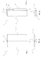
- said backpiece 1 comprises two panels 2, 3 substantially of equal dimensions.
- Each panel 2, 3 can rotate about a predetermined folding line X-X common to the two panels 2, 3.
- Said folding line X-X defines two matching edges 2a, 3a of the two panels intended to be mutually abutted.
- the backpiece 1 By rotating the two panels 2, 3 about the folding line X-X the backpiece 1 can assume various configurations, including its utilization configuration, shown in Figure 1, and its rest configuration, shown in Figure 2. While being moved from one position to the other, the backpiece 1 also assumes the configuration shown in Figure 3.
- the two panels 2, 3 When in their utilization configuration, the two panels 2, 3 are coplanar and lie side by side along the common folding line X-X.
- the two matching edges 2a, 3a mutually abut to enable the backpiece 1 to form a substantially continuous surface.
- a jointing rib is associated with said two matching edges 2a, 3a.
- said jointing rib is a strip 4 of deformable material.
- a material usable for forming the strip 4 is, for example, polyvinyl chloride (PVC) or polypropylene (PP).
- the abutting matching edges 2a, 3a are suitably trimmed by a trimming machine, to obtain an application surface for the strip 4 which is planar and homogeneous, while at the same time avoiding the undesirable effect of the typical slippage of the two panels commonly known as "scissoring".
- the two abutting edges 2a, 3a are essentially perpendicular to the plane of the two panels 2, 3.
- Adhesion of the strip 4 to the abutting edges 2a, 3a is ensured by interposing a thin layer of adhesive material, such as an EVA-based hot-melt glue, between the surface of the edges 2a, 3a and the surface of the strip 4.
- a thin layer of adhesive material such as an EVA-based hot-melt glue
- the hot-melt glue is melted by means of the known art and spread on the abutting edges 2a, 3a, for example by a brush or roller.
- a pressing machine After applying the glue, a pressing machine applies the strip 4 to the surface of the two abutting edges 2a, 3a and presses it thereon.
- the dimensions of the applied strip 4 are such as to cover at least the entire surface of the two abutting edges 2a, 3a.
- the optimum thickness of the strip 4 has been identified as 0.3 mm, however any other thickness not excessively different therefrom can be used depending on the specific utilization requirements of the backpiece 1.
- the strip 4 applied to the two abutting edges 2a, 3a is folded along the folding line X-X of the backpiece 1 when passing from the rest configuration ( Figure 2) to the utilization configuration ( Figure 1), enabling the two panels 2, 3 to remain joined together.
- the strip 4 is substantially invisible both because of its small thickness and because of the deformability of the material which is compressed between the two abutting edges 2a, 3a of the two backpiece panels.
- the backpiece for sectional furniture according to the present invention can be formed from panels of any material suitable for the purpose, such as chipboard faced with a plastic layer, or medium density fibreboard (MDF).
- MDF medium density fibreboard
- the backpiece for sectional furniture according to the present invention satisfies the requirements and overcomes the drawbacks stated in the introduction to the present description with reference to the known art.
- the backpiece for sectional furniture according to the present invention enables backpieces to be obtained which can also be used for furniture items having their rear located in such a manner as to remain visible, for example room-centre furniture.
- the strip present between the two panels becomes substantially invisible when the backpiece is set in its utilization configuration.
- Strips of the same colour as the panels can also be used, so further improving the appearance of the backpiece.
- the backpiece of the present invention can be formed with panels of any material.
- Another significant advantage of the backpiece for sectional furniture of the present invention is the facility to form backpieces with panels of large thickness, for example 10 mm and more.
Landscapes
- Engineering & Computer Science (AREA)
- Mechanical Engineering (AREA)
- Assembled Shelves (AREA)
Priority Applications (1)
| Application Number | Priority Date | Filing Date | Title |
|---|---|---|---|
| EP03425665A EP1523908A1 (de) | 2003-10-14 | 2003-10-14 | Rückwand für Anbaumöbel |
Applications Claiming Priority (1)
| Application Number | Priority Date | Filing Date | Title |
|---|---|---|---|
| EP03425665A EP1523908A1 (de) | 2003-10-14 | 2003-10-14 | Rückwand für Anbaumöbel |
Publications (1)
| Publication Number | Publication Date |
|---|---|
| EP1523908A1 true EP1523908A1 (de) | 2005-04-20 |
Family
ID=34354646
Family Applications (1)
| Application Number | Title | Priority Date | Filing Date |
|---|---|---|---|
| EP03425665A Withdrawn EP1523908A1 (de) | 2003-10-14 | 2003-10-14 | Rückwand für Anbaumöbel |
Country Status (1)
| Country | Link |
|---|---|
| EP (1) | EP1523908A1 (de) |
Cited By (3)
| Publication number | Priority date | Publication date | Assignee | Title |
|---|---|---|---|---|
| EP1792551A1 (de) * | 2005-11-30 | 2007-06-06 | Fritz Egger GmbH & Co. | Faltbare Platte |
| DE102007044711B3 (de) * | 2007-09-18 | 2008-11-27 | Heinrich Kuper Gmbh & Co Kg | Faltbare Platte sowie Verfahren zur Herstellung einer faltbaren Platte |
| DE102008051213A1 (de) * | 2008-10-14 | 2010-04-15 | Fritz Egger Gmbh & Co. | Faltbare Platte |
Citations (5)
| Publication number | Priority date | Publication date | Assignee | Title |
|---|---|---|---|---|
| DE19804787A1 (de) * | 1998-02-06 | 1999-08-12 | Atex Werke Gmbh & Co Kg | Verfahren zum Herstellen faltbarer Faserplatten |
| WO2001017411A1 (en) * | 1999-09-09 | 2001-03-15 | Mtd Industries Ltd. | Shower enclosure |
| DE20116405U1 (de) * | 2001-10-10 | 2002-01-17 | Hornitex Werke Gebr. Künnemeyer GmbH & Co. KG, 32805 Horn-Bad Meinberg | Plattenscharnier |
| DE20207222U1 (de) * | 2002-05-07 | 2002-10-02 | W. Lehbrink GmbH & Co. KG, Maschinenfabrik, 33813 Oerlinghausen | Gelenkig verbundene Plattenelemente |
| EP1275795A2 (de) * | 2001-07-11 | 2003-01-15 | E.F.P. Floor Products Fussböden GmbH | Fussbodenbelagselement mit Paneelen |
-
2003
- 2003-10-14 EP EP03425665A patent/EP1523908A1/de not_active Withdrawn
Patent Citations (5)
| Publication number | Priority date | Publication date | Assignee | Title |
|---|---|---|---|---|
| DE19804787A1 (de) * | 1998-02-06 | 1999-08-12 | Atex Werke Gmbh & Co Kg | Verfahren zum Herstellen faltbarer Faserplatten |
| WO2001017411A1 (en) * | 1999-09-09 | 2001-03-15 | Mtd Industries Ltd. | Shower enclosure |
| EP1275795A2 (de) * | 2001-07-11 | 2003-01-15 | E.F.P. Floor Products Fussböden GmbH | Fussbodenbelagselement mit Paneelen |
| DE20116405U1 (de) * | 2001-10-10 | 2002-01-17 | Hornitex Werke Gebr. Künnemeyer GmbH & Co. KG, 32805 Horn-Bad Meinberg | Plattenscharnier |
| DE20207222U1 (de) * | 2002-05-07 | 2002-10-02 | W. Lehbrink GmbH & Co. KG, Maschinenfabrik, 33813 Oerlinghausen | Gelenkig verbundene Plattenelemente |
Cited By (3)
| Publication number | Priority date | Publication date | Assignee | Title |
|---|---|---|---|---|
| EP1792551A1 (de) * | 2005-11-30 | 2007-06-06 | Fritz Egger GmbH & Co. | Faltbare Platte |
| DE102007044711B3 (de) * | 2007-09-18 | 2008-11-27 | Heinrich Kuper Gmbh & Co Kg | Faltbare Platte sowie Verfahren zur Herstellung einer faltbaren Platte |
| DE102008051213A1 (de) * | 2008-10-14 | 2010-04-15 | Fritz Egger Gmbh & Co. | Faltbare Platte |
Similar Documents
| Publication | Publication Date | Title |
|---|---|---|
| JP4004958B2 (ja) | ベニア加工されたレイズドパネルエレメントおよびその製造方法 | |
| CA2293141C (en) | Method for making corners for laminate and veneer countertops | |
| US20040111993A1 (en) | Veneered raised panel element and method of manufacturing thereof | |
| US6508899B1 (en) | System for applying edge trim to furniture panel | |
| US4814220A (en) | Countertop fabrication system | |
| US20250059820A1 (en) | Cabinet door assembly and manufacturing thereof | |
| EP1523908A1 (de) | Rückwand für Anbaumöbel | |
| CN215347844U (zh) | 板材端面用几何条和装饰层进行转折包边的端面无隙板材 | |
| JP2006283487A (ja) | 建具 | |
| CN218140368U (zh) | 一种免封边的家具板条 | |
| JPS5912283B2 (ja) | 収納具用化粧戸およびその製造方法 | |
| JP3635702B2 (ja) | フラッシュ構造の化粧板 | |
| US6399172B1 (en) | Hinged panel for furniture | |
| JP3977721B2 (ja) | 板状木製品のラッピング構造 | |
| US4619800A (en) | Method of making a decorative composite panel | |
| JP3200729B2 (ja) | 框 材 | |
| CN210067802U (zh) | 一种钢质门内外双包门套框 | |
| JPH066939Y2 (ja) | 縁どり台紙 | |
| JPS5912812A (ja) | 化粧シ−トを施した箱体の製造方法 | |
| JPH04161584A (ja) | ドア及びその製造方法 | |
| JPS6237685Y2 (de) | ||
| KR200188915Y1 (ko) | 입체무늬 테이프 | |
| JP3572812B2 (ja) | 化粧板及びその製造方法 | |
| KR200191975Y1 (ko) | 앨범용 시트 및 앨범 | |
| JPH07304010A (ja) | 化粧シート貼り木質パネル |
Legal Events
| Date | Code | Title | Description |
|---|---|---|---|
| PUAI | Public reference made under article 153(3) epc to a published international application that has entered the european phase |
Free format text: ORIGINAL CODE: 0009012 |
|
| AK | Designated contracting states |
Kind code of ref document: A1 Designated state(s): AT BE BG CH CY CZ DE DK EE ES FI FR GB GR HU IE IT LI LU MC NL PT RO SE SI SK TR |
|
| AX | Request for extension of the european patent |
Extension state: AL LT LV MK |
|
| AKX | Designation fees paid | ||
| REG | Reference to a national code |
Ref country code: DE Ref legal event code: 8566 |
|
| STAA | Information on the status of an ep patent application or granted ep patent |
Free format text: STATUS: THE APPLICATION IS DEEMED TO BE WITHDRAWN |
|
| 18D | Application deemed to be withdrawn |
Effective date: 20051021 |