EP2176377B1 - Polymerdispergierte flüssigkristallstrukturen - Google Patents
Polymerdispergierte flüssigkristallstrukturen Download PDFInfo
- Publication number
- EP2176377B1 EP2176377B1 EP08773656A EP08773656A EP2176377B1 EP 2176377 B1 EP2176377 B1 EP 2176377B1 EP 08773656 A EP08773656 A EP 08773656A EP 08773656 A EP08773656 A EP 08773656A EP 2176377 B1 EP2176377 B1 EP 2176377B1
- Authority
- EP
- European Patent Office
- Prior art keywords
- liquid crystal
- polymer
- film
- pdclc
- alignment
- Prior art date
- Legal status (The legal status is an assumption and is not a legal conclusion. Google has not performed a legal analysis and makes no representation as to the accuracy of the status listed.)
- Not-in-force
Links
Images


Classifications
-
- C—CHEMISTRY; METALLURGY
- C09—DYES; PAINTS; POLISHES; NATURAL RESINS; ADHESIVES; COMPOSITIONS NOT OTHERWISE PROVIDED FOR; APPLICATIONS OF MATERIALS NOT OTHERWISE PROVIDED FOR
- C09K—MATERIALS FOR MISCELLANEOUS APPLICATIONS, NOT PROVIDED FOR ELSEWHERE
- C09K19/00—Liquid crystal materials
- C09K19/52—Liquid crystal materials characterised by components which are not liquid crystals, e.g. additives with special physical aspect: solvents, solid particles
- C09K19/54—Additives having no specific mesophase characterised by their chemical composition
- C09K19/542—Macromolecular compounds
- C09K19/544—Macromolecular compounds as dispersing or encapsulating medium around the liquid crystal
Definitions
- the present invention relates to polymer-dispersed liquid crystal structures.
- the invention has particular application in areas such as: light control films for use in glazing applications that are capable of switching between transparent and opaque states, generally known as “switchable windows” or “smart windows”; see-through displays that comprise a matrix of pixels each capable of being selectively operated in a transparent or opaque state, for use in applications like shop front windows, or the window of a bus or train, without blocking visual access through the window (see for example PCT Application Nos.
- PCT/IE 02/00079 and PCT/IE00124 projection screens, in particular where the projection screen also functions as a window by being operated in an opaque scattering state when used for projection, and opaque or transparent states when used as a switchable window; normal-mode (i.e., opaque in the absence of power and transparent in the presence of power) light shutters and displays whether made with flexible substrates (e.g. film) or rigid substrates (e.g. glass); and bistable (i.e., selectively the opaque or transparent state is stable in the absence of power - power is only used when switching from one state to the other) light shutters and displays.
- normal-mode i.e., opaque in the absence of power and transparent in the presence of power
- light shutters and displays whether made with flexible substrates (e.g. film) or rigid substrates (e.g. glass)
- bistable i.e., selectively the opaque or transparent state is stable in the absence of power - power is only used when switching from one state to the other) light shutters and displays.
- LC devices of this type generally comprise a liquid crystal layer of controlled thickness (i.e. cell gap) sandwiched between two substrates.
- Each substrate is transparent and coated with a transparent, electrically conductive coating on the side facing the liquid crystal layer to enable an electrical field to be applied to the layer.
- the substrates may be glass or a polymer substrate film. If the substrates are film then it may be possible to laminate the liquid crystal film to regular window glass panes on one or both sides by employing an adhesive sheet known as an interlayer.
- Such a combined LC film and glass laminate is known as a switchable window.
- Saint Gobain Vitrage sells a switchable window laminate under the brand name "Priva-Lite".
- the process of laminating a liquid crystal film between glass panes using one or more interlayer sheets subjects the film to pressure, elevated temperature, and vacuum. Difficulties can arise due to mismatched thermal expansion indices between the different materials. Furthermore, even after lamination, subsequent handling of the finished laminate can subject the LC layer to shear forces as the two glass panes (sandwiching the LC layer) flex, especially if the window is greater than 1 meter in any direction. In order for the film to withstand the lamination process and subsequent handling it is necessary for the LC layer to have a polymeric (or other) structure to support the liquid crystal.
- the main technologies of polymer-LC structure are:
- PDLC or NCAP devices have a continuous polymer structure (typically making up 40 - 60% of the liquid crystal layer) having discrete cavities that contain liquid crystal.
- the liquid crystal (nematic type) is said to form droplets within a continuous polymer matrix.
- PSCT devices also rely on liquid crystal material dispersed throughout a polymer, but in PSCT devices the polymer does not encapsulate the liquid crystal in discrete droplets; instead it provides a thin, fibrous polymer network that extends into and/or through a continuous liquid crystal layer.
- PDCLC devices are bistable, colour reflective devices (unlike the PDLC/NCAP and PSCT devices which are selectively transmissive).
- PDCLC devices have a cholesteric liquid crystal material dispersed in relatively larger droplets within a polymer matrix, with the LC material being switchable between two bistable states - one being highly reflective of a narrow band of visible wavelengths, and the other being weakly scattering.
- Polymer Dispersed Liquid Crystal (PDLC) and Nematic Curvilinear Aligned Phase (NCAP) refer to two very similar technologies distinguished from one another by the techniques used to create the respective devices. However, for the purposes of the following discussion, the end result of each technology is effectively the same.
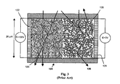
- Fig. 1 shows an example of a PDLC device.
- the structure 114 consists of a 20 ⁇ m thick film composed of a polymer matrix or structure in which droplets 116 of nematic liquid crystal material have been captured by phase separation during polymerization.
- PDLC and NCAP type films are flexible, can be cut to size from a continuous roll of film (as the liquid crystal is encapsulated by the polymer structure), and function without the need for polarizers (inherently required by twisted nematic (TN) type devices).
- TN twisted nematic
- the liquid crystal droplets are generally spherical and have a diameter of about 0.7 ⁇ m to 1.0 ⁇ m.
- Figs. 2A and 2B illustrate that in the presence of a 100V AC field ( Fig. 2A ) the liquid crystal 116 displays birefringence, with the refractive index of the polymer 114 matching that of the liquid crystal in the direction parallel to the major axis of the film (i.e., the ordinary refractive index, n o ), while in the absence of such a field ( Fig. 2B ), the mean refractive index of the LC material is mismatched with that of the polymer (n polymer ⁇ n effective LC), resulting in scattering at each boundary between liquid crystal and polymer crossed by a light ray passing through the film.
- PDLC and NCAP devices suffer from significant haze in the ON state as the viewing angle increases, and can become opaque for large viewing angles.
- the haze is caused by light scattering at the boundary or interface between the field-aligned, nematic, liquid crystal in the droplets and the encapsulating polymer.
- a mismatch between the refractive index of the polymer and that of the liquid crystal in the droplets due to its inherent birefringence is the reason.
- the ordinary refractive index of the liquid crystal is matched to the refractive index of the isotropic polymer matrix to minimize haze. But, as the viewing angle increases in the ON state the significance of the mismatch between the polymer and the liquid crystal becomes more dominant (n polymer ⁇ n effective L.C.) and light scattering at the interface increases causing haze.
- PDLC and NCAP devices Another drawback of PDLC and NCAP devices is that in the OFF state (no electrical field) scattering light efficiency is determined by the difference between the mean refractive index of the liquid crystal and the refractive index of the polymer matrix. It follows from this that interface surface must be maximized by minimizing droplet size and maximizing the number of droplets. The minimum size is dictated by the wavelengths of visible light, and so PDLC and NCAP displays typically have a mean droplet diameter of 0.7 ⁇ m - 1 ⁇ m (this refers to the major axis as the droplets may not be spherical).
- a light ray could encounter 10 droplets or more, each having the potential to contribute to haze in the ON state, even for viewing angles close to normal. This demonstrates the inherent trade-off in PDLC devices whereby increasing the scattering power in the OFF state increases the haze in the ON state.
- US 5,604,612 discloses a PDLC device of this type, and discusses how scattering power can be maximized by optimizing the difference between the mean refractive index of the liquid crystal and the polymer matrix.
- FIG. 3 An example of a normal-mode Polymer Stabilised Cholesteric Texture (PSCT) film is shown in Fig. 3 .
- PSCT Polymer Stabilised Cholesteric Texture
- the polymer in this device does not encapsulate the liquid crystal in discrete droplets, but rather it provides a thin, fibrous polymer network 120 that extends into and/or through a continuous liquid crystal layer 122 as shown in Fig. 3 . It has been shown that the polymer is effective in separating the continuous liquid crystal layer into domains that individually switch quicker than a continuous layer without polymer.
- the liquid crystal is of the type known as cholesteric or chiral nematic. Because the LC layer is continuous, the film must be sealed using a seal such as that shown schematically at 129.
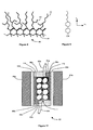
- a chiral dopant is added to nematic liquid crystal to impart an alignment between molecules 127, see Fig. 4 , each at a slight angle to the next, which traces out a helical structure.
- the distance required for one full twist of the helix is known as the pitch.
- the pitch can be adjusted by adjusting the concentration of the chiral dopant.
- the planar texture reflects a band of visible light (this type of device is known as reflective); but when the pitch is increased further the reflected light will move into the infrared range, and light in the visible range is transmitted (this type of device is known either as normal or reverse mode).
- the focal conic texture is similar to the planar texture in that the chiral dopant imposes a helical alignment between liquid crystal molecules, but unlike the planar texture, the axes of the helices align poorly with respect to each other - see texture on right hand side 126 of Fig. 3 . Poor alignment creates an angular difference that results in the effective refractive index of the liquid crystal in one helix (or in one domain containing aligned helices) being different from its neighbouring helices (or domains) thereby causing light scattering at the boundaries. Consequently, PSCT devices have a different scattering mechanism, namely the focal conic texture, to that of PDLC devices.
- a polymer network In addition to the switching benefits of separating the liquid crystal into domains, a polymer network also exerts a stabilizing influence whereby the liquid crystal molecules adjacent the polymer interface take on an alignment. This alignment may be sufficient to stabilize a cholesteric liquid crystal domain in one or more of its three possible states (or textures) in the absence of power: planar (light reflecting and transmitting), focal conic (light scattering and/or transmitting), and homeotropic (clear or transparent).
- the principal function of the polymer is to stabilize the focal-conic texture.
- the more fibrous the polymer network the more effective it is in inducing random alignment of the helical axes (i.e. creating multiple domains) in the focal conic texture, and consequently a strong scattering state that blocks visual access through the PSCT film.
- a polymer network or other means such as polymer surface artefacts, to stabilize the focal conic texture, then on removing power random helical alignment will not persist, i.e. such a texture is not stable over time. In this case the focal conic texture will revert to a weak scattering/transmitting state typical of reflective PSCT devices.
- the homeotropic texture is the only texture that is common to both PSCT and PDLC devices.
- the helices unwind in PSCT films and the liquid crystal director (i.e., the common direction of the long axes of the liquid crystal molecules) aligns parallel to the field (assumes positive dielectric anisotropy) - see texture on left hand side of Fig. 3 .
- US 5,437,811 teaches normal (opaque in the absence of power) and reverse-mode (transparent in the absence of power) PSCT light-shutters that are virtually haze-free regardless of viewing angle, and have superior optical clarity to PDLC and NCAP displays even when viewing normal to the display. While the polymer percentage of the liquid crystal layer can be up to 40%, and the polymer type can be isotropic or mesogenic (i.e., a Liquid Crystal Polymer LCP), generally such devices will only exhibit good optical clarity when the polymer percentage is ⁇ 10%. In addition, an electrical or magnetic field must be present during curing, and this is undesirable in a continuous film manufacturing line.
- US 7,023,600 discloses a method to make bistable, PSCT films for switchable-window applications, whereby selectively the focal conic (strong light scattering) or planar (visible light transmitting - transparent) states are stable in the absence of power.
- the disclosed switchable window film has the advantage that power is used only when switching from one state to the other, and no power is consumed to maintain the window in either the planar / transparent or strongly-scattering, focal conic states. While this is particularly attractive for battery-powered applications, the disclosed bistable device requires relatively high frequency (>1 KHz) switching when changing from clear to opaque, and the feasibility of applying high frequency switching to large-area (i.e., >1M 2 ) light shutters having film substrates needs to be demonstrated.
- the polymer structure in PSCT cells is only directed to bridging both substrates when polymer network is formed from substantially mesogenic monomer in the presence of an electrical field.
- an electrical field or for isotropic monomers
- a substantial part of the polymer will form on the surface of the substrates, particularly the substrate facing the ultra-violet light curing source, resulting in a polymer layer that contributes very little to film structure. If the polymer content (and/or monomer functionality) is increased to force more bridging, then the optical clarity suffers greatly as found in US 6,049,366 for PSCT examples having >20% polymer.
- PSCT devices whether produced on film or glass substrates, are characterized by relatively little increase in haze with viewing angle when compared to PDLC devices. This accrues from having the liquid crystal in a continuous layer. Optical clarity is best when the polymer content, present in the liquid crystal region as polymer network, is ⁇ 10%. PSCT devices have an alternative scattering mechanism to PDLC devices, focal conic texture, but require a polymer network to stabilize the focal conic texture with sufficient scattering power to block visual access. However, despite having superior optical characteristics to PDLC devices, PSCT films made according to prior art methods have insufficient mechanical strength to be suitable for the demands of the applications contemplated herein.
- FIG. 5 An example of a reflective, bistable PDCLC film is shown in Fig. 5 , which again shows the two states alongside one another, in this case the reflective planar texture on the left, as indicated at 130, and the weakly scattering focal conic texture on the right, as indicated at 132.
- the film again has a pair of substrates 110 carrying electrodes 112, which sandwich a polymer structure 114.
- the liquid crystal is provided as larger volumes 116, as explained further below.
- PDCLC devices do not rely on a polymer network to stabilize the liquid crystal textures, rather the anchoring of the liquid crystal molecules to the polymer surface is sufficiently strong and uniform to induce the planar state.
- the focal conic state only weakly scatters light because the same polymer surface anchoring which allows for a stable planar texture also imposes a strong ordering within the focal conic texture. This can be seen by comparing the weakly scattering focal conic texture of Fig. 5 with the strongly scattering texture of Fig. 3 .
- weak scattering is highly desirable, but it makes such devices unsuitable for switchable windows and similar applications.
- PDLC type displays are compared to reflective PDCLC displays in the article titled " Flexible Encapsulated Cholesteric LCDs by Polymerization Induced Phase Separation", by Tod Schneider et al. in the Society for Information Display SID 05 Digest, pages 1568 - 1571 .
- the article is based on disclosures in US Patent Publication No. 2007/0026163 .
- “In a typical PDLC the droplets are generally spherical, less than 1 micron in diameter, and are numerous in number throughout the thickness of the cell.
- the droplets are more pancake in shape, on the order of magnitude of ⁇ 10 micron (or more) in diameter, and are singular throughout the thickness of the cell.
- the article's PDCLC displays operate in the reflective and scattering (to a light-absorbing back plane) modes, i.e., [they] have very little light scattering in both modes”.
- polymer / cholesteric liquid crystal dispersions are provided in which, similar to PDLC devices, the liquid crystal phase separates into discrete droplets within a continuous polymer matrix.
- the disclosed droplets in the reflective PDCLC displays have a major axis that is greater than the cell gap (i.e., the thickness of the layer containing the polymerized liquid crystal).
- the cell gap is shown as 4 ⁇ m.
- the patent teaches that by having the droplet size much larger than the pitch of the cholesteric liquid crystals, inside the droplets the liquid crystal molecules behave similar to surface modified reflective cholesteric devices.
- a reflective PDCLC with memory i.e., bistable
- the focal conic state is so weakly scattering as to be described as being transparent.
- the contrast of a PDCLC display is degraded if there is more than a single layer of droplets sandwiched between the electrodes at most points of the display. It is further stated that preferably the droplets have a ratio thickness:length from 1:2 to 1:6.
- Reflective, bistable PDCLC devices can be prepared by adopting the methods used in PDLC and NCAP devices.
- US 6,061,107 uses the method known as Thermally Induced Phase Separation TIPS to prepare the PDCLC disclosed
- US 6,556,262 uses the emulsification method (also used by NCAP devices)
- a photoradical Polymerization Induced Phase Separation PIPS method is described.
- liquid crystal devices containing polymer walls or polymer networks e.g., PSCT devices
- PSCT devices have faster switching times (i.e. turn ON and OFF) and lower operating voltage than devices without such walls or networks.
- PDLC displays are an exception in that the small droplet size typical of such films is known to increase switching times and operating voltage.
- US 6,203,723 discloses a PDLC type film having microencapsulated droplets that contain not just nematic liquid crystal, but also polymer network (similar to PSCT devices).
- the polymer network disrupts the alignment of the nematic liquid crystal within droplets causing domains to form therein, each domain has a different liquid crystal molecular alignment, and the polymer network stabilizes the alignment. While such devices have improved switching characteristics, and light scattering, the polymer network within droplets will cause increased haze as the interface surface area between polymer and liquid crystal is significantly increased. Light refracts not just at a droplet's polymer surface, but also as it enters and leaves the dense polymer network within a droplet. Such devices are unsuitable for the applications contemplated herein because of their high level of haze in the ON state.
- US 5,455,083 discloses a cholesteric liquid crystal optical shutter for projection type applications having superior operating voltage without loss of switching speed.
- the polymer is said to be formed into a structure of thin cell walls, and the introduction of these cell walls is said to create more focal conic domains per volume when compared with a continuous cholesteric liquid crystal layer that does not contain any polymer.
- the scattering properties of the disclosed device are not compared with a conventional PDLC film, and it is likely that scattering occurs principally at the interface between a polymer wall and the liquid crystal - similar to PDLC devices. There is nothing in the document to show that the scattering within droplets, at the boundaries of polydomains, is anything other than weak, and the latter scattering mechanism is not discussed in the document.
- the OFF state is only required to scatter a 2mm parallel light beam by plus or minus 0.57 degrees (2mm aperture at 100mm from the device) for it not to be received by the sensor.
- the light scattering available from such devices is not sufficient to block visual access in films used for glazing applications.
- the patent's examples 1 and 2 show that a film with 9% polymer content has good light transmission normal to the device's surface - 90% - but that this falls to 75% when the polymer content is 15% - example 3.
- the reduced light transmission in the latter example is caused by light scattering (i.e., haze) in the ON state. This shows that such devices have significant haze and are unsuitable to meet the haze-free viewing requirements of the applications contemplated herein.
- devices of the type disclosed in US 5,455,083 are unsuitable for the glazing applications contemplated herein because they have insufficient scattering power in the OFF state, suffer from too much haze in the ON state, have insufficient structural strength at the polymer content disclosed, and lastly, the liquid crystal / polymer composite film is not self sealing as discrete droplets of liquid crystal are not formed.
- US 5,455,083 is also the inventor of a number of related devices having improved switching characteristics in common, for example: US 2004/0017523 , US 6,924,873 , WO 01/55782 and WO 02/093241 . Similar to US 5,455,083 , the polymer content is 10% or less and the polymer system is also similar.
- the liquid crystal device in US 2004/0017523 for example is said to have the liquid crystal / polymer composite film of the type in JP4119320 .
- the polymer network in the latter is described as "a three dimensional mesh shape" and is shown in the document's drawings as allowing interpenetrating regions or volumes of liquid crystal.
- nematic liquid crystal molecules are shown aligning parallel to each other and perpendicular to the local polymer wall surface. For the reasons cited previously for US 5,455,083 , these devices are not suited for the applications contemplated herein.
- US 5,559,615 envisages a PDLC device for use in an active matrix type display where substituting the prior art nematic liquid crystal with a cholesteric type liquid crystal will improve such a device's turn-off time and light scattering. On turning off the electrical field the "(chiral) twisting force strongly acts between the liquid crystal molecules.
- the aligned state (ON) of the liquid crystal molecules is quickly returned to a twisted/aligned state.
- the light scattering power will be increased "Since liquid crystal molecules are set in a twisted/aligned state in the absence of an electric field, the randomness (degree) of alignment of liquid crystal molecules is high, and the difference between the refractive indexes of the polymer resin and liquid crystal constituting the polymer dispersed liquid crystal film is large.”
- the document sees the scattering mechanism as being refraction of light at the liquid crystal / polymer interface. Nowhere in the document is it envisaged that light scattering will occur at the boundaries between liquid crystal domains within droplets.
- the document envisages using the same polymer system as in prior art PDLC devices, specifically that shown in the document's prior art Figures 13A and 13B.
- Figure 13A nematic liquid crystal molecules adjacent the polymer surface are shown aligned parallel to the local surface.
- the document does not show how to form the polymer structure, or what the characteristics of that structure might be. For example, the following are unknown: the prepolymer components, the percentage weight of each component, the percentage weight of polymer in the liquid crystal mixture, suitable types of nematic liquid crystal and chiral dopants, or UV curing conditions.
- the invention provides a polymer-dispersed liquid crystal system, comprising a continuous polymer structure having defined therein a plurality of discrete bodies of liquid crystal material, wherein the liquid crystal material is cholesteric liquid crystal and the pitch of the liquid crystal is greater than 0.8 microns, said bodies of liquid crystal material exhibiting a polydomain operating state in which the liquid crystal material within each body is arranged in multiple domains, at least 75% of the bodies of liquid crystal having a largest dimension in the range 2.5 to 3.5 microns, the bodies of liquid crystal having a bulk volume which is free of polymer networks or walls, each domain being defined by a quantity of liquid crystal material whose molecules have a substantially common identifiable alignment in at least one axis, wherein the resolved alignments of neighbouring domains diverge substantially from one another and are stable over time, and wherein at the interface between a liquid crystal body and the polymer structure, the polymer surface's molecular structure influences the liquid crystal molecules to assume an alignment which diverges from the plane of the polymer surface.
- scattering primarily occurs at the inter-domain boundaries within the individual bodies of liquid crystal (LC) material when that material is in its polydomain state.
- LC liquid crystal
- This can be distinguished from PCLD/NCAP devices where scattering occurs primarily at the LC/polymer boundaries of the droplets due to a refractive index mismatch (when in the OFF state).
- scattering occurs primarily at the LC/polymer boundaries of the droplets, and scattering within droplets is weak because of strong ordering of the LC helices both at the polymer interface and consequently within a droplet's liquid crystal bulk.
- Such devices lack highly divergent domains within the bodies of LC material.
- PSCT devices have LC domains
- the LC material is not in discrete bodies and the polymer is not a continuous structure. Indeed the very features that promote the domain formation are the filaments of polymer extending through the LC material and such filaments do not provide the structural strength of a continuous polymer structure.
- said bodies of liquid crystal material in the polymer-dispersed liquid crystal systems of the invention, can also be influenced to exhibit a uniform operating state in which the majority of the liquid crystal molecules within each discrete body of liquid crystal material assume a substantially common identifiable alignment in at least one axis.
- transitions between the polydomain and uniform states can be caused by the application to said structure of a suitable electromagnetic signal or field.
- said bodies of liquid crystal material can also be influenced to exhibit a range of intermediate states between said polydomain and uniform operating states, resulting in said polymer-dispersed liquid crystal system having optical properties intermediate between those exhibited in the polydomain and uniform operating states.
- said liquid crystal assumes a focal conic texture in said polydomain operating state.
- said polydomain operating state scatters light within a liquid crystal body by refracting light at each boundary between divergent domains.
- the system further comprises dye molecules in the liquid crystal bodies, wherein said polydomain operating state scatters and absorbs light within a liquid crystal body by refracting light at each boundary between divergent domains and absorbing light as it passes through dye molecules within domains.
- said liquid crystal is a cholesteric liquid crystal operated in normal-mode.
- said polymer structure is a film and said bodies of liquid crystal are formed therein as discrete, dispersed droplets.
- a majority of said discrete bodies of liquid crystal material have a volume falling within a range bounded by an upper and a lower limit, said lower limit being the minimum volume capable of possessing multiple domains having substantially divergent alignment in the polydomain operating state, and said upper limit being the maximum volume at which a substantially divergent alignment of domains can still be retained and stabilized within said body in the polydomain operating state.
- the range of the present invention's droplet volume differs from prior art PDCLC displays because in order to achieve substantially divergent alignment at the lower volume limit the droplet volume must be greater than prior art devices having the same droplet size as PDLC displays (i.e., 0.7 ⁇ m to 1.0 ⁇ m).
- PDLC displays i.e., 0.7 ⁇ m to 1.0 ⁇ m.
- their droplet volume is too large to stabilize and sustain a droplet's liquid crystal bulk in a substantially divergent alignment of domains due to the short pitch of their helices, and the parallel surface alignment of the liquid crystal/polymer interface; consequently, after turning off an electrical field they resolve to a weakly divergent focal conic texture over time.
- the largest dimension of at least 75% of the liquid crystal bodies within the polymer structure is in the range of 3.0 to 17.5 microns.
- the total polymer/liquid crystal interface surface area corresponding to a centimetre square of viewing surface, and expressed in units of centimetres square, where X is a film's cell gap and Y is a film's fraction of liquid crystal by weight, is in the range of 1,714XY to 24,000XY; more preferably in the range of 2,400XY to 20,000XY; and most preferably in the range of 3,429XY to 20,000XY.
- said liquid crystal material is a cholesteric liquid crystal material having a cholesteric pitch
- the maximum liquid crystal body volume is defined by a maximum dimension of up to thirty times the cholesteric pitch of the liquid crystal material.
- the pitch of the cholesteric liquid crystal is > 0.9 micron, and most preferably > 1 micron.
- the pitch of the cholesteric liquid crystal is > 1.0 micron, more preferably > 1.2 micron, and most preferably > 1.3 micron.
- the pitch of the cholesteric liquid crystal is > 1.0 micron, more preferably > 1.2 micron, and most preferably > 1.3 micron.
- chiral dopant(s) is added to nematic liquid crystal to make it cholesteric, and preferably one or more chiral dopant components has a Helical Twisting Power (HTP) magnitude that is > 20, and more preferably > 30.
- HTP Helical Twisting Power
- said bodies are ellipsoid and have a ratio of major axis length to minor axis length of less than 3:1.
- Said bodies can also be generally spherical ellipsoid bodies and have a major axis length to minor axis length ratio of less than 1.5 to 1.
- the system is provided as a generally planar structure and said bodies have a generally polygonal cross section when viewed from a direction normal to the plane of said structure.
- the polymer surface's molecular structure influences the liquid crystal molecules to assume an alignment that diverges from the plane of the polymer surface.
- This feature of the polymer surface influencing the molecules to have a divergent alignment relative to the plane of the polymer surface is very different from conventional systems in which the goal is to align the LC molecules either parallel to or perpendicular to the polymer surface to achieve the sought-after textures.
- the majority of neighbouring liquid crystal molecules at the polymer surface do not have substantially the same alignment and they substantially diverge from one another.
- the domains that contain liquid crystal molecules that are adjacent the polymer surface have alignments that also diverge from one another, in substantially different directions.
- said molecular structure at said polymer surface comprises substituent functional groups extending from the polymer backbone into the liquid crystal material, and said substituent functional groups cause said mutually divergent alignment within the liquid crystal material adjacent the polymer surface.
- said liquid crystal material exhibits a focal conic texture when in said polydomain state, and said substantially divergent domains in said focal conic texture are caused by substantially divergent alignment of liquid crystal molecules at the polymer surface.
- said substituent functional groups support liquid crystal molecule interdigitation, and due to steric effects, said substituent functional groups are spaced apart or tilted sufficiently to allow interdigitized liquid crystal molecules to tilt or assume an angle to the local normal to the polymer surface.
- the majority of said liquid crystal molecules adjacent the polymer surface lie at angles to the local normal to the polymer surface of from 10 to 80 degrees.
- the majority of said liquid crystal molecules adjacent the polymer surface lie at angles to the local normal to the polymer surface of from 20 to 70 degrees. Most preferably, the majority of said liquid crystal molecules adjacent the polymer surface lie at angles to the local normal to the polymer surface of from 25 to 65 degrees.
- said substituent functional groups extending from the polymer backbone into the liquid crystal material are substantially formed from one or more monofunctional monomers.
- the substituent functional groups comprise a linear chain having greater than or equal to four carbon atoms.
- said substituent functional groups can further comprise one or more branches of one or more carbon atoms extending from said linear chain between the second and antepenultimate linear carbon atoms.
- said branches each have greater than or equal to two carbon atoms in a chain.
- said substituent functional groups are formed substantially from monofunctional monomer 2-ethyl hexyl methacrylate.
- the polymer is formed from a polymer precursor comprising an acrylate crosslinker and acrylate monofunctional monomers, or a methacrylate crosslinker and methacrylate monofunctional monomers.
- crosslinker trimethylolpropane trimethacrylate comprises thirty percent or more of the total crosslinker monomer(s) weight, and most preferably is the sole crosslinker.
- the polymer is formed from a polymer precursor comprising primary and secondary monomers, the secondary monomer being a monofunctional monomer, being in the minority by percentage weight, and being substantially consumed before said primary monomer has formed the polymer surface interface with said liquid crystal bodies.
- said secondary monofunctional monomer is isobornyl methacrylate or ethyl methacrylate.
- the ratio of polymer precursor to liquid crystal material in the prepolymerization solution is from 10:90 by percentage weight to 70:30 by percentage weight, and more preferably from 20:80 by percentage weight to 50:50 by percentage weight.
- the invention also provides a method of preparing a polymer-dispersed liquid crystal system by polymerization induced phase separation, comprising the steps of:
- said step of initiating polymerization comprises exposing said mixture to electromagnetic energy to photo-radically cure said prepolymers.
- the polymer structure can be formed in the absence of an electrical or magnetic field, and does not require the liquid crystal molecules to be uniformly aligned during curing.
- the invention also provides a liquid crystal device comprising a polymer-dispersed liquid crystal structure as aforesaid in the form of a film, a pair of substrates sandwiching said film and bonded to said film, each substrate having a conductive electrode coating on the side facing said polymer-dispersed liquid crystal film to facilitate applying an electric field across said film.
- Said substrates can also be a polymer film and have a transparent conductive electrode coating on one side.
- the invention maximises the stabilized divergence of domains in the polydomain state of a liquid crystal device by selecting the rate of discharge of said device while transitioning from the homeotropic state to the polydomain state.
- the device is preferably provided as a continuous roll, allowing an individual device to be cut to size from a roll of said device while maintaining the integrity of the individual device.
- the device is preferably provided in a thickness that is operable in a uniform state that is transparent and substantially haze-free to the human eye for a range of viewing angles up to 30 degrees from the normal, and in a polydomain state that blocks visual access through said film.
- the conductive electrode coating on at least one substrate is patterned to provide independently and selectively addressable electrode areas.
- the polymer structure of said device has sufficient internal structural strength and adhesion to said polymer substrates as to be able to withstand lamination to glass panes in processes compatible with ethylene-vinyl acetate (EVA) interlayer use.
- EVA ethylene-vinyl acetate
- the invention also provides a glazed structure comprising a pair of transparent load-bearing sheets sandwiching a liquid crystal device as set out above.
- One or both of said transparent load-bearing sheets can be a glass pane; alternatively, one or both is an acrylic sheet.
- monomer refers to material containing molecules that are generally in single molecule form as opposed to compounds of such monomers such as dimers, trimers, tetramers, quadramers, pentamers, octamers, decamers, etc. or, oligomers - polymers with relatively low number of units.
- Fig. 6 shows a polymer-dispersed liquid crystal structure according to the invention in the form of a film 1 in the strongly light scattering state characteristic of the zero electrical field/OFF state.
- Incident light ray 20 enters the film 1 normal to its surface but is refracted at the boundaries between liquid crystal domains in droplets 12.
- Light ray 20 is shown exiting film 1 at a significant angle to the normal.
- Light ray 21 enters at about 30 degrees to the surface normal but is effectively internally reflected and exits through the same surface as it entered.
- light ray 22 is incident at an acute angle and it too is scattered to exit at some significantly different angle.
- Fig. 7 shows a polymer-dispersed liquid crystal structure according to the invention in the form of a film 1 in the clear/transparent state for visible light wavelengths characteristic of a suitably strong electrical field/ON state.
- the display When viewed about the normal to the face of the substrates, as indicated by light ray 23, the display is substantially free of haze, and has clarity close to that of glass.
- haze increases slightly with its level dependant on droplet 12's volume for a given cell gap and the liquid crystal birefringence.
- the liquid crystal's refractive index is n e and is referred to as the extraordinary refractive index.
- the direction of the liquid crystal refractive indices in the homeotropic state is indicated by numeral 17.
- a droplet 12 contains cholesteric liquid crystal whose molecules are aligned into helical structures, referred to by numerals 13a, 13b and 13c.
- each domain there is a refractive index mismatch with neighbouring domains, the greater this refractive index mismatch, which arises from the divergence of the helical axes and the birefringence of the liquid crystal, the more strongly light will be refracted.
- the axes of the helical structures 13a, 13b and 13c are not parallel, so each belongs to a different domain within a droplet 12.
- the present invention maximizes the opaqueness of the OFF state by maximising the number of domains, and the divergence of domains, that are stabilized within a droplet 12.
- the film 1 employs cholesteric liquid crystal in the droplets 12, which are themselves polymer-dispersed
- the device and film will be referred to for brevity as a PDCLC (polymer-dispersed cholesteric liquid crystal) device or film.
- PDCLC polymer-dispersed cholesteric liquid crystal
- the scattering power of the focal conic texture in a PDCLC film can be increased from the weak, semi-transparent scattering state typical of reflective, bistable PDCLCs, see Fig. 5 , to a strongly scattering polydomain texture that is stabilized in the OFF state, see Fig. 6 , by applying the containment means defined herein.
- the efficacy of the containment means lies in the discovery that a discrete volume of cholesteric liquid crystal (a droplet 12), when confined in a polymer structure 14, has a range of volumes that possess the surprising property of stabilizing a polydomain texture in the OFF state.
- cholesteric liquid crystal with a pitch longer than taught in the prior art has a number of important advantages.
- the cholesteric liquid crystal pitch is about 50% or more longer than the typical prior art pitch for normal-mode PSCT shutters of ⁇ 0.8 micron.
- PDCLC films having a long pitch - for example, 1.4 microns - have the following advantages in the OFF state over films having a short pitch - for example, 0.8 to 0.95 microns:
- the chiral dopant can be a single compound, or a mixture.
- Example 2 uses a single chiral dopant having a HTP of about 33.5, whereas example 3 used two dopants: one having a HTP of about -13.8 and the other a HTP of -33.5.
- Films having the formulations shown in these examples have an increased upper volume limit for droplets when compared to the formulation of example 1 whose chiral dopant has a HTP of about 13.8.
- divergent surface anchoring plays in determining scattering power in the OFF state. It has been found that the scattering power of the focal conic texture in a PDCLC film can be maximized by achieving what is called herein "divergent surface anchoring" at the polymer/liquid crystal interface within droplets. Divergent surface anchoring can be achieved through polymer surface architecture (i.e., selection of monomers that result in the desired surface) as will be elaborated on later in this document.
- Parallel surface anchoring of a liquid crystal molecule at the interface with a droplet's polymer surface is where the director of a liquid crystal molecule exhibits a preferential alignment to that surface. If a droplet's polymer surface can induce substantially the same alignment - parallel alignment - in the majority of neighbouring liquid crystal molecules at the polymer interface then this is called herein "parallel surface anchoring". In the prior art examples of parallel surface anchoring are referred to as planar (i.e., where the long-range molecular alignment is parallel to the polymer surface), and homeotropic (i.e., where the long-range molecular alignment is perpendicular to the polymer surface and parallel to each other).
- Reflective, bistable, PDCLC films have planar alignment of liquid crystal molecules at the polymer/liquid crystal interface within droplets.
- PDLC films typically have homeotropic alignment but can also have planar alignment.
- NCAP have planar alignment.
- PSCT films the liquid crystal molecules at the interface with a polymer network formed from mesogenic polymer are homeotropically aligned.
- Divergent surface anchoring is where the majority of neighbouring liquid crystal molecules at the interface with a polymer surface do not have the same alignment in the axis normal to the local surface, rather their alignments diverge from one another.
- one liquid crystal molecule may be at 60 degrees to the local polymer surface normal, its neighbouring molecule on one side may be at 25 degrees and its neighbouring molecule on the other side may be at 45 degrees.
- a liquid crystal molecule's alignment can be mapped on a rectangular Cartesian Coordinate System: the axis normal to the surface can be though of as the Z-axis, then the X and Y axes are in the plane of the surface. In this case a liquid crystal molecule parallel to the local surface lies in a plane parallel to the X and Y axes.
- a liquid crystal molecule can be thought of as a line segment: when parallel to the local surface all points along a molecule's line segment have the same Z axis co-ordinate; when lying perpendicular to the local surface all points on a segment have the same X and Y axes coordinates; and, when lying at an angle to the Z axis all points on a segment can have either the same X or Y axis co-ordinates, but not both, or have co-ordinates different in all three axes.
- the latter, a line segment with co-ordinates different in all three axes is typical of the liquid crystal alignment of divergent surface anchoring.
- parallel and divergent surface anchoring refers to the alignment of the end molecules of the cholesteric liquid crystal spiral structures - helices - at the polymer interface.
- the chirality forces in cholesteric liquid crystal impose helical structuring of its liquid crystal molecules - see Fig. 4 .
- the minimum structure is half a helical pitch and the length is in increments of half pitches.
- divergent surface anchoring the angle a helix's end molecule makes with the polymer surface has to be resolved between the competing forces of liquid crystal chirality and polymer surface anchoring in cases where the surface alignment would otherwise result in helices clashing due to space constraints.
- divergent surface anchoring refers to this resultant alignment of the end liquid crystal molecules of helices at the polymer interface.
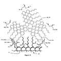
- Fig. 10 shows an example of the divergent surface anchoring of the present invention resulting from poly(2-ethylhexyl methacrylate) 40.
- the neighbouring, helical-end, liquid crystal molecules 50a and 50b diverge from each other.
- molecules 51a and 51 b are parallel.
- end molecule 52 is forced to align differently to 50a and 50b as a consequence of the divergence of the helical structures containing 50a and 50b.
- the direction of the ordinary and extraordinary liquid crystal refractive indices of each of the three domains containing end molecules 50a, 50b and 52 are shown by 53a, 53b and 54 respectively.
- the effective refractive index of each of these three neighbouring domains will be significantly different to each other and cause light to scatter (i.e., refract) at their respective boundaries.
- the axes of the helices at the polymer interface will tend to be parallel for substantially parallel surface anchoring and will tend to be divergent for substantially divergent surface anchoring.
- the containment means on turning off the electrical field from the ON state, there is significant turbulence in the liquid crystal bulk as the collapsing homeotropic alignment of liquid crystal molecules is converted into helical alignment by the chirality forces of the cholesteric liquid crystal. It has been found that during this transitionary period the newly formed domains in the liquid crystal bulk are divergent and that this divergence can be captured, and stabilized by containment means, thereby creating a strongly-scattering, polydomain texture that persists over time.
- the containment means encapsulates a discrete volume of liquid crystal, whose volume falls within a range defined herein, in a cavity - referred to as a droplet 12 - in a polymer structure 14.
- An upper volume limit of a droplet 12 (i.e., the containment means) was found at the point where forces within the liquid crystal bulk dominate over the containment forces imposed by a droplet's volume, allowing the helical axes to move into less divergent alignments.
- the resultant state is a weakly scattering focal conic texture.
- a lower volume limit of a droplet 12 (i.e., the containment means) was found at the point where the volume is so small that the majority of domains have a polymer wall interface.
- a droplet's shape can dominate alignment of domains, and regardless there are insufficient domain boundaries within a droplet to create significant light scattering within droplets. The latter is the case for prior art PDCLC devices having the same droplet size as PDLC displays (i.e., 0.7 ⁇ m to 1.0 ⁇ m).
- the upper and lower volume limits of a droplet 12 were found to be dependant on the helical pitch, and to a lesser extent on the HTP magnitude of the chiral dopant.
- concentration of chiral dopant along with its HTP magnitude determine the helical pitch; for a given HTP, the lower the concentration the larger the pitch and so the longer the helical major axis. It is proposed that larger helices have less freedom of movement in a given droplet volume than smaller helices.
- a polydomain texture can be stabilized over time by the containment means of the present invention.
- known polymer means of stabilizing a polydomain texture involve the use of a fibrous polymer network that extends through the liquid crystal bulk (i.e., PSCT devices), but advantageously, the present invention avoids polymer altogether within the liquid crystal bulk as such polymer network or walls would provide additional polymer/liquid crystal interface surfaces that would contribute to haze in the ON state.
- the more a surface becomes defined by parallel rather than divergent anchoring the more likely that one: the helical axes of the liquid crystal will align resulting in larger domains in the polydomain texture thereby reducing the amount of boundary surfaces where light can be scattered, and two, that the angle between the helical axes of neighbouring domains will reduce thereby reducing the refractive index mismatch, and so, scattering power.
- divergent surface anchoring creates divergent domain alignment of the liquid crystal at the polymer interface, in turn these divergent domains cause or reinforce divergence of neighbouring domains within the bulk, and so on towards the centre of the bulk. Effectively, divergent domains are created both by the liquid crystal turbulence on turning off the electrical field, and the polymer surface as helices align at divergent angles to the surface.
- a PDCLC film having the droplet morphology of the present invention and made with monomers resulting in substantially divergent surface anchoring, has higher stabilized scattering power than a corresponding film having similar droplet morphology but made with monomers resulting in substantially parallel surface anchoring.
- the shape of a droplet 12 is less important than its volume, but the shape is significant in terms of its impact on the total polymer surface area of a droplet (due to the aligning influence of the polymer surface), or where one of its axes is so short as to inhibit the formation of a significant liquid crystal bulk comprising multiple domains in the direction of that axes.
- the preferred shape is one that is broadly ellipsoidal, and the "pancake/flattened" shape (i.e., having one or more relatively planar surfaces) droplets of reflective PDCLCs is less desirable (see Fig. 5 ). It will be appreciated by a person of ordinary skill in the art that a PIPS process cannot be controlled to form perfect geometric forms; the references here to geometric forms are to be understood as meaning broadly recognizable or closest to a particular form.
- its largest axis is ⁇ 3 times its smallest axis, and more preferable ⁇ 2, and still more preferable two of its axes are approximately equal - spheroid shape.
- a droplet may have a generally polygonal cross section in an axis parallel to the film surface.
- PDCLC films with a relatively short helical pitch are the most sensitive: droplets having a maximum axis in the range of 2.5 to 4.0 ⁇ m are preferably discharged over 10 ms to 300 ms, and most preferably over 50 ms to 200 ms; for larger droplets, particularly greater than 5 ⁇ m, the discharge rate is preferably 0.5 ms to 10 ms, and most preferably 1 ms to 3 ms.
- PDCLC films with relatively long helical pitch simply benefit from a discharge of less than about 300 ms and there is no dependency on droplet size.
- the rate of discharge can be controlled simply by a resistor whose size is selected based on the capacitance (i.e., the area) of a PDCLC film, and the desired discharge time given said film's helical pitch.
- a resistor whose size is selected based on the capacitance (i.e., the area) of a PDCLC film, and the desired discharge time given said film's helical pitch.
- electrode 11a (see Fig. 11 ) is connected to the SPDT switch's pole / common, the normally open contact is connected to the driving signal's "+" polarity, and the normally closed contact is connected through the discharging resistor to signal ground; and, electrode 11b is connected directly to the driving signal's "-" polarity. In this way the discharging resistor is out of the circuit when the PDCLC film is powered (switch thrown to the normally open position), but discharges the PDCLC film when not powered (switch thrown to the normally closed position).
- the presence of a suitably strong electrical field causes the helical axes of the cholesteric liquid crystal of the present invention to unwind, the polydomains of the focal conic texture to disappear, and the liquid crystal molecules to align parallel to the electrical field (for liquid crystal with positive dielectric anisotropy), see Fig. 7 .
- the liquid crystal has a homeotropic texture, is highly ordered, and a droplet can be thought of as comprising a single liquid crystal domain.
- a light ray normal to the film surface in Fig. 7 e.g., ray 23
- a ray normal to a PDLC film will encounter typically 10 to 15 droplets.
- minimizing the number of droplets significantly reduces the amount of haze for a given cell gap and liquid crystal birefringence, particularly haze at acute angles of view.
- the volume becomes a single domain with a common liquid crystal alignment, within this domain there is negligible scattering of visible light regardless of angle.
- a droplet's volume is increased, ultimately to occupy an entire local space within a film, then that local space has negligibly haze regardless of angle. Consequently to minimize haze in the ON state a droplet's volume must be maximized.
- droplets whose size is towards the maximum size of the criteria disclosed, to use droplets that are more spherical in shape than ellipsoidal, and to avoid droplets completely whose largest axis is ⁇ 1.5 ⁇ m as these contribute very little to scattering power but significantly to ON state haze at acute viewing angles.
- PDCLC films having a long pitch - for example, 1.4 microns - have the following advantages in the ON state over films having a short pitch - for example, 0.8 to 0.95 microns:
- the current invention discloses a range of values for the polymer/liquid crystal interface area corresponding to a centimetre square of viewing surface in terms of cell gap (X) and a film's LC fraction (Y):
- the range for the polymer/LC interface area for such a PDCLC film is from 3.6 cm 2 to 50.4 cm 2 .
- the corresponding interface area for a typical PDLC or NCAP film having an average droplet diameter of 1 micron is 126 cm 2 .
- a 4.25 ⁇ m cell is haze-free (i.e., glass like) regardless of viewing angle; a 6.5 ⁇ m cell remains haze free for light rays 23 and 24, but there is a slight perception of haze as the acute viewing angle of light ray 25 increases (60° - 90° from normal); and, a 10 ⁇ m cell has a slightly more haze than a 6.5 ⁇ m at acute viewing angles.
- example 3 shows that a 14 micron film made with droplets whose major axis is about double that of the example 1 films had a similar level of haze at acute viewing angles to the 6.5 micron film in example 1 despite example 3 having significantly more scattering power (due to the increased cell gap) in the OFF state.
- the refractive index of the polymer matrix is matched to the ordinary refractive index of the liquid crystal, similar to the practice in PDLC films.
- the refractive index of the polymer matrix has a liquid crystal component in its value as some liquid crystal is trapped in the polymer matrix during polymerization.
- the refractive index of the polymer matrix can be matched to an intermediate value between the ordinary and extraordinary refractive indices of the liquid crystal.
- liquid crystal within a discrete droplet volume is free of any polymer in an amount sufficient to form any networks, walls or other structures inside a droplet volume.
- the domain boundaries within a droplet are defined by adjacent liquid crystal volumes and not by liquid crystal/polymer boundaries inside the volume of the droplet.
- liquid crystal displays can be operated to have "grey” states.
- PDCLC devices of the present invention can also be operated to exhibit a range of intermediate states between the polydomain (OFF) and homeotropic (ON) operating states, resulting in intermediate optical properties.
- a wider range of intermediate states is available by using prior art methods of applying and maintaining an intermediate voltage level between zero volts and that required for homeotropic alignment.
- the domains and helices experience an electrical field and will alter their state according.
- the degree of converging of domains, or unwinding of helices, is controlled by the applied field, and thereby directly controls the degree of scattering (or transparency).
- the minimum cell gap possible that still satisfies an applications requirement for scattering power in the OFF state it is desirable to use the minimum cell gap possible that still satisfies an applications requirement for scattering power in the OFF state.
- PDCLC films made in accordance with the present invention's requirements for droplet morphology and divergent polymer surface anchoring have sufficiently strong scattering to block visual access through the film, or through glass, acrylic or polycarbonate laminates containing the film, for cell gaps ⁇ 6.5 ⁇ m.
- the scattering power of the present invention's PDCLC film can be equivalent to typical PDLC, NCAP or PSCT films having a 20 ⁇ m cell gap.
- This innovation allows use of a significantly smaller cell gap in PDCLC films of the present invention to achieve comparable scattering power to prior art films with the consequences that less liquid crystal is required, costs are lowered, and operating voltage reduced.
- the birefringence of a liquid crystal is minimized while maintaining the cell gap at prior art values: 20 to 25 micron typically.
- the refractive index mismatch between the liquid crystal and the polymer at a droplet's interface is significantly lowered. Scattering power within a droplet is reduced because the refractive index mismatch between domains in the polydomain texture is reduced, but this is compensated for by the increase in the cell gap and so the number of domain boundary scattering sites in the polydomain texture.
- a PDCLC film of the present invention can be readily optimized to meet requirements for haze-free viewing and scattering power by varying the cell gap, and selecting liquid crystal with more or less birefringence as required.
- the cell gap 16 is preferably in the range: 4 ⁇ m to 75 ⁇ m, and more preferably 5 ⁇ m to 25 ⁇ m.
- PDCLC films of the present invention including monomers, photoinitiators, nematic liquid crystals, and chiral dopants, and associated polymerization conditions for forming a layer of PDCLC material between transparent, conductive substrates.
- Polymerization Induced Phase Separation PIPS cured photoradically, is the preferred method of the present invention.
- a photoinitiator is used that decomposes under UV radiation to produce free radicals that initiates chain-growth polymerization.
- the polymeric chains grow in molecular weight and droplets of liquid crystal are excluded from the bulk via phase separation. These droplets coalesce forming larger droplets whose size is ultimately fixed at polymerization termination.
- the polymer precursors comprise two or more unsaturated monomers and a photoinitiator.
- One or more of the monomers, in the minority by percentage weight, is multifunctional and is generally referred to as a crosslinker.
- the other monomer(s) is monofunctional.
- the crosslinker is crucial to achieving dispersed liquid crystal droplets in a continuous polymer matrix. Without sufficient crosslinker in the polymer precursor the liquid crystal could remain in one or more large continuous phases similar to a PSCT device.
- the precursors of the polymer matrix usually contain one or more thiol monomers and / or oligomers that act as the principle crosslinking agent.
- the other monomers are alkene (also known as olefm or vinyl) compounds and have lower functionality: acrylate types, especially as oligomers, are used in conventional PDLCs, but methacrylate types can also be used.
- An example of a commonly used precursor for the matrix of PDLC displays is Norland Products, Inc. optical adhesive NOA65.
- This consists of thiol monomer TMPTMP - trimethylolpropanetri(3-mercaptopropionate), commercial epoxy acrylate oligomer Ebecryl E270, acrylate monomers EHA - 2-ethyl-hexanolacrylate - and HDDA - hexanedioldiacrylate, and commercial photoinitiator D 1173.
- the acrylate crosslinker trimethylolpropane triaacrylate TMPTA is used as a polymer precursor in the bistable, reflective PDCLC films featured in " Flexible Encapsulated Cholesteric LCDs by Polymerization Induced Phase Separation", by Tod Schneider et al. in the Society for Information Display SID 05 Digest, pages 1568 - 1571 .
- Ethyl methacrylate EMA is the monomer and Irgacure 651 the photoiniator.
- suitable acrylates and methacrylates have a variety of substituent functional groups that can be classified as linear alkyl, branched alkyl, aryl, alkylaryl, arylakyl, multiple arylalkyl, alkylmultiplearyl, alkylcycloalkyl, cycloalkylalkyl, hydroxyalkyl, fluoroalkyl, fluoroaryl, alkylsiloxane, siloxanealkyl, siloxanearyl, and arylsiloxane groups.
- the selection of a particular acrylate or methacrylate for a particular mixture is accomplished using the criteria described herein.
- Examples of acrylates for use in the present invention that have a plurality of functional groups and so potentially suitable as the crosslinker, whether as the sole crosslinker or in combination with other crosslinkers, in the polymer precursor are: diethyleneglycol diacrylate, 1,4-butanediol diacrylate, 1,3-butyleneglycol diacrylate, dicyclopentanyl diacrylate, glycerol diacrylate, 1,6-hexanediol diacrylate, neopentylglycol diacrylate, tetraethyleneglycol diacrylate, trimethylolpropane triacrylate, pentaerythritol tetraacrylate, pentaerythritol triacrylate, tripropyleneglycoldiacrylate, ditrimethylolpropane tetraacrylate, dipentaerythritol hexaacrylate, dipentaerythritol monohydroxypentaacrylate, urethane
- methacrylates for use in the present invention that have a plurality of functional groups and so potentially suitable as the crosslinker, whether as the sole crosslinker or in combination with other crosslinkers, in the polymer precursor are: ethyleneglycol dimethacrylate , diethyleneglycol dimethacrylate, 1,4-butanediol dimethacrylate, 1,3-butyleneglycol dimethacrylate, dicyclopentanyl dimethacrylate, glycerol dimethacrylate, 1,6-hexanediol dimethacrylate, neopentylglycol dimethacrylate, tetraethyleneglycol dimethacrylate, 1,4-butanediol dimethacrylate, bisphenol-A dimethacrylate, trimethylolpropane trimethacrylate, pentaerythritol tetramethacrylate, pentaerythritol trimethacrylate, ditrimethylol
- acrylates for use in the present invention that are monofunctional and so potentially suitable as the monomer, whether as the sole monomer or as a comonomer, in the polymer precursor are: ethyl acrylate, 2-ethylhexyl acrylate, 2-ethyl-hexanolacrylate, butylethyl acrylate, butoxyethyl acrylate, 2-cyanoethyl acrylate, benzyl acrylate, cyclohexyl acrylate, 2-hydroxypropyl acrylate, hydroxyethyl acrylate, 2-ethoxyethyl acrylate, N,N-diethylaminoethyl acrylate, N,N-dimethylaminoethyl acrylate, isooctyl acrylate, dicyclopentanyl acrylate, dicyclopentenyl acrylate, glycidyl acrylate, tetahydrofurfuryl acrylate
- methacrylates for use in the present invention that are monofunctional and so potentially suitable as the monomer, whether as the sole monomer or as a comonomer, in the polymer precursor are: ethyl methacrylate, methyl methacrylate, 2-ethylhexyl methacrylate, butylethyl methacrylate, butoxyethyl methacrylate, 2-cyanoethyl methacrylate, benzyl methacrylate, ethylbenzyl methacrylate, n-hexyl methacrylate, n-octyl methacrylate, n-decyl methacrylate, cyclohexyl methacrylate, 2-hydroxypropyl methacrylate, 2-ethoxyethyl methacrylate, N,N-diethylaminoethyl methacrylate, N,N-dimethylaminoethyl methacrylate, dicyclopentanyl methacrylate
- the prepolymer monomers for use in the present invention are preferably acrylate or methacrylate liquid compounds that are miscible with chiral nematic liquid crystal and form a homogeneous solution prior to polymerization.
- monomers are chosen in preference to oligomers or resins of these monomers to promote miscibility with the viscous chiral nematic liquid crystal.
- the reactivity ratios are a measure of the affinity for each reactive component (i.e. monomer) to react with each other reactive component.
- the monomer reactivity ratios are the ratios of the rate constant for a given radical adding its own monomer to that for it adding the other monomer. In a mixture of two monomers, if a monomer's ratio r monomer > 1 the monomer prefers to react with itself, and if r monomer ⁇ 1 it prefers to react with the other monomer(s). It follows that a monomer with a ratio > 1 will be consumed in the polymerization reaction faster than a monomer with a ratio ⁇ 1.
- the reactivity ratio for a monofunctional monomer(s) with itself, in a mixture with the chosen crosslinker monomer is preferably > 1, more preferably > 2.5, and most preferably > 5.
- the latter means that the monofunctional radical is 5 times more likely to react with its monomer than with the crosslinker monomer.
- the crosslinker preferably exhibits very low reactivity with itself substantially preferring to react with the monofunctional monomer(s) in the polymer precursor.
- the reactivity ratio for the crosslinker monomer(s) with itself is: preferably ⁇ 1, more preferably ⁇ 0.4, and most preferably ⁇ 0.20.
- a crosslinker's percentage weight in the polymer precursor of the present invention can be approximated by taking into account its rate of consumption (based on the reactivity ratios), its molecular weight, and its functionality.
- Crosslinker % weight / monofunctional monomer % weight Molecular mass of crosslinker / molecular mass of monofunctional monomer / ( rate of monofunctional monomer reactions to crosslinker reactions * functionality of the crosslinker )
- the crosslinker % weight: monofunctional % weight 1:9 in the polymer precursor.
- the upper limit of the crosslinker's % weight is somewhat less (e.g. ⁇ 10% less) than indicated by the preceding balanced system formula. This will ensure that mostly monofunctional monomer is present near the end of polymerization and so the polymer surface of droplets will be formed predominantly from monofunctional monomer. This is important to achieving the required surface architecture - divergent surface anchoring - through monofunctional monomer selection. It is also advantageous in that only the monofunctional monomer(s) needs to have its refractive index (or more accurately its resultant refractive index as it could have a trapped liquid crystal component in it) match the ordinary refractive index of the liquid crystal.
- the preceding balanced system formula is a guide to the crosslinker's % weight
- the preceding paragraph discloses the crosslinker's upper limit, and its lower limit is determined by the capability of the polymer system to phase separate the liquid crystal into discrete droplets.
- the crosslinker percentage weight must be sufficient to form droplets.
- the desired droplet morphology is achieved by the following steps:
- the initial chemical intuition is that a methacrylate / methacrylate pairing will have closer reactivity ratios than a methacrylate / acrylate pairing, or vice versa.
- This intuition relies on the nature of the reactive vinyl bond and its immediately adjacent bonded groups having a greater impact on reactivity than the - O-linked side groups more distant from the vinyl bond. Though this chemical intuition is no substitute for determining the reactivity ratios, it is a useful guide as to general compatibility of pairings.
- the overall reactivity of the polymer precursor must also take into account the viscous nature of the chiral nematic liquid crystal within the mixture.
- the slower reactivity of an acrylate crosslinker system over a thiol-type system and the even slower reactivity of a methacrylate crosslinker system, is preferred.
- monomers are preferred to oligomers or resins.
- the polymer interface is substantially formed from monofunctional monomer as the crosslinker is used up near the end of polymerization but prior to forming the droplet surface.
- the polymer molecules are chain linked, and their substituent functional groups (the substituent groups of the monofunctional monomer(s) in the polymer precursor) extend into the liquid crystal and are thought to interact at the molecular level with the liquid crystal molecules. This molecular level interaction at the interface is subject to chirality forces of the liquid crystal bulk as discussed earlier, and how these are resolved determines whether the resultant surface anchoring is classified as parallel or divergent.
- the substituent functional groups of monofunctional monomers can be classified as linear alkyl, branched alkyl, aryl, alkylaryl, arylakyl, multiple arylalkyl, alkylmultiplearyl, alkylcycloalkyl, cycloalkylalkyl, hydroxyalkyl, fluoroalkyl, fluoroaryl, alkylsiloxane, siloxanealkyl, siloxanearyl, and arylsiloxane groups.
- substantially parallel alignment of liquid crystal molecules is typical of most monomers' substituent functional groups, and substantially divergent alignment required in the present PDCLC film, particularly one leading to strongly scattering stabilized polydomain texture, cannot readily be achieved unless the selection methods contained herein are applied.
- preferred monomers for creating divergent surface anchoring when substantially one monofunctional monomer creates a droplet's polymer surface, are those whose substituent functional groups preferably have long linear chains, ⁇ 4 carbon atoms; more preferably the substituent functional groups have both long chains, and one or more branched chains, and especially where the branch occurs at or between the second and antepenultimate linear carbon atoms; and most preferably the substituent functional groups have both long chains, and one or more branched chains occurring at or between the second and antepenultimate linear carbon atoms, and where the branch is a group having ⁇ 2 carbon atoms, for example 2-ethylhexyl methacrylate EHMA.
- the latter is the preferred monofunctional monomer of the present invention.
- Fig. 8 shows a droplet's 12 surface, poly(2-ethylhexyl methacrylate) 40, formed by polymerizing monofunctional monomer 2-ethylhexyl methacrylate EHMA.
- Numeral 41 indicates the polymer backbone; 42, the hexyl long linear carbon chain having 6 carbon atoms; and 43, the ethyl branch having 2 carbon atoms and occurring at the second carbon atom of the hexyl chain.
- Fig. 10 the substituent functional groups 42 and 43 of a droplet's polymer surface containing poly(EHMA) 40 are shown interacting with chiral nematic liquid crystal molecules 50a and 50b as described earlier. While a liquid crystal molecule can align parallel, perpendicular or at an angle to the polymer surface, the latter is the most probable for poly(EHMA) making it well suited to creating the strongly divergent surface anchoring of the present invention.
- EHMA's ethyl branch 43 forces neighbouring EHMA substituent functional groups to tilt due to steric effects thereby allowing a liquid crystal molecule to align at an angle to the normal to the local polymer surface.
- Steric effects arise from the fact that atoms within a molecule occupy a certain amount of space, and if atoms are brought too close together, there is a cost in energy due to overlapping electron clouds, and this may affect the molecule's preferred shape.
- the long hexyl chain 42 (6 carbon atoms) supports interdigitation of liquid crystal molecules when taken together with the ethyl branch 43 being at the second carbon atom (i.e., leaving 4 carbon atoms after the branch to interact with the liquid crystal molecule).
- the position of the ethyl branch at the second carbon atom is also thought to be significant in minimizing steric effects from the polymer backbone that otherwise would favour parallel alignment.
- the monofunctional monomer component of the polymer precursor can contain more than one monomer.
- the additional monomer(s) in this case can play two different roles.
- the first role is where the additional monomer is added to improve physical properties of the PDCLC film such as greater strength, flexibility or adhesion of the polymer matrix to the substrates. In this role it is normally undesirable to have the additional monomer present in a droplet's polymer surface as a copolymer.
- the additional monomer will be substantially used up in forming the bulk of the polymer matrix, leaving only the preferred monomer near the end of polymerization to form the surface of the droplets.
- IBOMA isobornyl methacrylate
- the second role of additional monofunctional monomer is where the additional monomer cooperates with the preferred monomer to improve or create divergent surface anchoring.
- the reactivity of the monofunctional monomers must be similar so that both are present to form a copolymer surface at a droplet's liquid crystal interface.
- monofunctional monomers used to create a droplet's polymer surface must cooperate to align neighbouring, or near neighbouring, liquid crystal molecules at divergent angles.
- Substituent functional groups extending into the liquid crystal from the polymer/copolymer backbone are characterized in that the substituent groups must support liquid crystal molecule interdigitation, and due to steric effects, must space apart or tilt substituent groups sufficiently to allow interdigitized liquid crystal molecules to tilt or assume an angle of preferably 10 to 80 degrees with the normal to the local polymer surface; more preferably 20 to 70 degrees, and most preferably 25 to 65 degrees.
- the resultant angle a helix's end molecule makes with the polymer surface has to be resolved between the competing forces of liquid crystal chirality and polymer surface anchoring in cases where the surface alignment would otherwise result in helices clashing due to space constraints at the interface.
- the liquid crystal alignment produced by the polymer surface of the present invention - divergent surface anchoring - is not random, rather, as disclosed, it is the result of the interaction between the polymer's substituent functional groups, as selected in accordance with the present invention, and the liquid crystal molecules at the interface.
- the photoinitiator added to the prepolymer can be any of the types suited to free-radical polymerization such as for example, benzoin methyl ether BME (available from Sigma Aldrich), or 2,2-dimethoxy-1,2-diphenylethan-1-one known as Irgacure 651 (available form Ciba Speciality Chemicals), or any other photoinitiators from the Irgacure family such as 184, 819 or 907.
- the photoinitiator is added at the rate of 1 - 10% by weight of the monomers (i.e., including crosslinker and monofunctional monomer); and more preferably at 1.125 - 3%.
- cholesteric liquid crystal molecules that exhibit chirality can be used, chiral nematic liquid crystal mixtures are preferred.
- a chiral dopant is added to a nematic liquid crystal to create the helical twist ordering (ie. cholesteric phase) characteristic of cholesteric liquid crystal.
- Varying the concentration of chiral dopant to nematic liquid crystal varies the pitch of the resultant helices. The shorter the pitch, the greater the twisting power required, and so the higher the chiral dopant concentration.
- chiral dopants have significantly higher viscosity than nematic liquid crystals, so there is a trade-off between cholesteric liquid crystal viscosity and pitch length.
- ⁇ np
- HTP can have a positive or negative value depending on whether right-handed or left-handed twisting is used. In the current application either can be used once all dopants added have the same sign, what is important is the magnitude of the HTP and not its sign.
- Suitable chiral dopants and nematic liquid crystal compounds are readily available commercially from a number of sources, and will be known to those of ordinary skill in the art.
- the earlier cited US 7,023,600 lists the chemical composition of suitable nematic liquid crystal compounds, and chiral dopants, as well as listing commercially available products and sources.
- both the chemical composition of suitable compounds and commercially available products are listed in US 7,119,859 . In the latter case they are disclosed for use in a reflective, bistable PDCLC devices prepared by the emulsification method.
- any transparent flexible plastic substrate - indicated by numerals 10a and 10b in Figs. 6 and 7 - coated with a transparent electrically conductive surface - 11a and 11b - on the side facing the PDCLC layer is suitable, and will be known to those of ordinary skill in the art.
- a comprehensive list of suitable plastic substrate materials, and suitable transparent conductive materials is disclosed in the earlier cited US 7,119,859 for use in flexible display applications.
- prior art glass and/or rigid substrates coated with a transparent electrically conductive coating can be used for conventional display applications.
- Polyethylene terephthalate PET substrates coated with indium tin oxide ITO conductive surface are preferred for use in the applications contemplated herein because such films are readily available commercially from a number of sources, are very cost competitive, and compatibility with switchable window applications has already been demonstrated.
- a range of substrate thickness and ITO resistivity are available: preferred are 100 ⁇ m - 175 ⁇ m and 40 - 300 ohms/square respectively.
- optical coatings may be applied under the ITO layer to reduce light reflectance.
- Other functional coatings such as a barrier layer, insulating layer, alignment layer or hard coat may also be applied to the substrate film as are known in the prior art.
- spacers for use in the present invention to space apart the substrates and control the thickness of the PDCLC layer in a PDCLC film.
- Any transparent spherical spacer suitable for use in liquid crystal display applications can be used, and will be known to those of ordinary skill in the art.
- Exemplary PDCLC films prepared herein used high precision plastic spacers under the trademark Micropearl SP available from Sekisui Chemical GmbH.
- the spacers can be applied before filling with the polymer /LC mixture (typical for glass and rigid substrates), or mixed with the polymer / LC mixture prior to laminating between film substrates. The latter is the preferred method.
- the % weight of spacer in the polymer / LC mixture is in the range 0.1% - 10%; more preferably 0.25% - 5%, and most preferably 0.5% - 3%.
- the polymer precursor - crosslinker(s), monomer(s) and photoinitiator - may be prepared separately and added to the liquid crystal mixture, or both can be prepared at the same time.
- the mixture may be heated sufficiently to dissolve any solids completely, for example, a photoinitiator or a chiral compound may be in crystalline form on adding to the mixture.
- Prior art mixing methods include vortex, shaker, and ultrasonic mixing.
- the mixture may be filtered if required to remove any possible aggregate, and then spacer material added and thoroughly mixed depending on the fabrication method.
- the mixture is degassed to remove air (e.g., by placing in a vacuum chamber). The mixture is then ready for lamination between substrates.
- the PDCLC mixture of the present invention may be first coated onto one substrate by methods such as doctor blade, gravure coating, curtain coating, die-coating, printing, or screen printing, and then the other substrate may be laminated to the coated substrate.
- the PDCLC layer can be simultaneously laminated between film substrates as disclosed in the earlier cited US 6,049,366 . In all these methods the PDCLC mixture is preferably precisely metered along the coating / laminating head to ensure sufficient flow of material but avoid wastage. If rigid substrates are used such as glass, the PDCLC mixture can be vacuum filled by conventional means.
- the laminated PDCLC layer is polymerized with UV light whose peak intensity preferably matches the absorption profile of the photoinitiator.
- the PDCLC film of the present invention does not require an electrical field to orient the liquid crystal molecules during polymerization. This greatly facilitates curing the film in a substantially continuous roll as the need for electrical connection and device isolation during curing is avoided.
- many prior art PSCT devices require the presence of an electrical field during polymerization necessitating the curing of the film in device /sheet form as opposed to a substantially continuous roll.
- a PDCLC device of the present invention can be cut from a polymerized roll to the required size by known methods such as hand cut by scissors / shears, cut on a slitter table, or laser cut. Typically, only 1-3 droplets in width are affected by the cutting action leaving a device fully functional up to its cut edge, and, inherently sealed.
- the PDCLC film of the present invention is robust, flexible, and typically can withstand bending from a corner, or being rolled up on a core diameter of 100 mm or more.
- two rolls of substrate film are unwound continuously under tension and simultaneously feed to a coating station where the PDCLC mixture is precisely metered and a uniform PDCLC layer is formed between the substrates whose cell gap is precisely maintained by spacers, and this prepolymerization laminate is fed directly to an inline UV curing station with sufficient travel (given line speed) and light intensity to fully cure the PDCLC layer, and the cured PDCLC film is wound onto a receiving roll under tension.
- the PDCLC film / glass laminate applications contemplated herein, and sometimes referred to as switchable windows, can be prepared using prior art methods.
- a sheet of PDCLC film can be cut from a roll of such film to the window size required.
- Methods to provide electrical connection ledges on a PDCLC film are similar to prior art PDLC devices.
- a connection ledge can be made by slitting one substrate to the required width for a connection ledge at one end of the film, peeling off the slit section of substrate to reveal the PDCLC layer beneath, wiping away the PDCLC layer to expose the ITO surface of the other substrate with a wipe soaked in isoprop alcohol or similar, printing and curing a conductive layer on the exposed ITO, and bonding a copper or other suitable buzz-bar to the conductive ledge thus prepared to facilitate attachment of an electrical cable and distribution of an electrical signal uniformly along the length of the connection ledge.
- the window film may then be switched between opaque and transparent to confirm its optical quality.
- Fig. 11 shows a glazing structure comprising PDCLC film 1 laminated between glass panes 61a and 61b.
- connection ledges are prepared: copper or other highly conductive flexible material, 63a and 63b, is bonded to ITO surfaces 11a and 11b respectively via conductive adhesive and / or conductive ink 64a and 64b; polarized driving signals can be applied to the PDCLC film via bonded / soldered cables 65a and 65b respectively.
- the PDCLC film of the present invention can be laminated to a regular window glass pane on one or both sides by employing an adhesive sheet known as an interlayer.
- the PDCLC film 1 is laminated on both sides to glass panes 61a and 61 b via interlayers 62a and 62b respectively.
- the interlayer can be polyvinyl butyral PVB, ethylene-vinyl acetate EVA or polyurethane PU, and advantageously incorporates a UV blocking function.
- an EVA interlayer is used as these have the lowest maximum processing temperature.
- a vacuum-bag glass laminating process is preferred over an autoclave.
- Suitable interlayer films for use with the present invention include EVASAFE from Bridgestone Corporation, Japan, and SLEC from Sekisui, Japan.
- Process guidelines for laminating PET films (i.e., the preferred substrate material of the present invention) to glass are available from both suppliers.
- the resultant glass laminates made with PDCLC film in accordance with the present invention are free of discernable glass laminating related defects, have not suffered any objectionable optical degradation as a consequence of glass lamination, and possess suitable robustness in all window sizes.
- the PDCLC film of the present invention is well suited to the applications contemplated herein.
- the surface of the liquid crystal encapsulating wall preferably provides divergent surface anchoring at its interface with the liquid crystal as disclosed herein.
- the resultant encapsulated liquid crystal droplets in the polymer binder / matrix are preferably as disclosed herein in relation to droplet morphology.
- Exemplary emulsification systems used in NCAP devices are disclosed in EP 0,238,164 and US patent numbers 4,435,047 , 4,806,922 , and 4,732,456 . As discussed earlier US 6,556,262 uses an improved emulsification system in its reflective, bistable PDCLC device.
- the preferred application of the device of the current invention to an emulsification type process is where the liquid crystal is first encapsulated by polymer in shells/balls (hollow spheres having a skin of polymer and liquid crystal encapsulated therein), subsequently the LC shells are mixed with prepolymer components that form the polymer matrix thereby becoming a suspension prior to coating onto the substrate(s).
- An exemplary emulsification system is disclosed in US 5,976,405 for PDLC devices.
- the advantages for the device of the current invention include:
- the opaque state i.e., the polydomain texture
- the light scattering state of normal-mode cholesteric devices can be converted to a partially or substantially light blocking state by the addition of a small amount (0.5% - 5%) of dye, preferably dichroic dye, to the liquid crystal mixture in accordance with the absorption profile of the added dye.
- dye preferably dichroic dye
- black dichroic dye will give a dark, light absorbing, opaque, OFF state.
- the corresponding homeotropic texture can have a slight colour tint due to the dichroic dye but remains transparent as the dye molecules' long axes are aligned parallel to the liquid crystals' long axes (i.e., the liquid crystal director).
- the advantages of dye use in the films of the present invention are two fold: creation of a light blocking state analogous to a conventional blind / shutter, and two, increased contrast in devices used to display information or images.
- a dichroic dye molecule In the OFF state, a dichroic dye molecule will take the place of a liquid crystal molecule in a helical structure.
- the substantially divergent alignment of domains in the present invention ensures that the alignment of dichroic dye molecules in neighbouring domains is also substantially divergent thereby promoting uniform light absorption regardless of viewing angle.
- light scattering at domain boundaries works efficiently with light absorption within domains (by dichroic dye molecules) to both reduce light transmission (i.e., block) and deny visual access (i.e., scatter light) in the OFF state.
- any known materials that add functionality can be used in the present invention.
- any known materials that add functionality to the polymer can be added to the polymer precursor in the present invention.
- the UV light source was an array of Philips black light tubes - F40T12BL - outputting long wave UV light with a peak at about 365nm. Measurements of UV intensity were taken at the PDCLC device, which was located 160 mm from the tubes. The PDCLC devices were cooled by circulating air to minimize any heating by the tubes during curing. The UV intensity during curing was measured by a Research Radiometer model IL1700 fitted with a SED400 detector and filter and optics having a peak response at 365 nm.
- the substrates were 175 ⁇ m PET coated with ITO having a resistivity of 80 ohm 2 /cm.
- the product used was OC80 supplied by CPFilms, Inc. California, US.
- the spherical spacers were from Sekisui Chemical's Micropearl range.
- the connection buzzbars were copper foil tape with conductive adhesive, available from 3M, part number 1181. All liquid crystal components were supplied by Merck KgaA, and all monomers and photoinitiators were supplied by Sigma Aldrich (www.sigma- aldrich.com).
- the laminated display was then cured at the UV light intensity level indicated in each example for 10 minutes.
- a 3M copper foil was bonded to the connection ledges provided by the offset substrates.
- an AC, square-wave generator was used having variable voltage amplitude (a variac can equally be used to supply AC sinusoidal driving signals). Simply having a resistor in the discharge path as disclosed earlier varied the discharge time. An oscilloscope was used to measure the discharge time.
- a PDCLC film was laminated to glass following inspection, as follows:
- TMPTMA Trimethacrylate
- the liquid crystal was a mixture of nematic type MDA-00-3506 and cholesteric mixture MDA-01-1955.
- the resultant pitch lies in the range 0.85 to 0.95 micron, and the peak reflection wavelength (see earlier formula) lies in the range 1.4 to 1.56 micron.
- the HTP of the chiral dopant in MDA-01-1955 is believed to be about 13.8.
- the liquid crystal birefringence is about 0.25.
- PDCLC films After a pair of PDCLC films was laminated, they were cured at a UV intensity of 6 mW/cm 2 for 10 minutes. Similarly, pairs of 6.5 ⁇ m and 10 ⁇ m PDCLC films were prepared (all components in the same proportion, except that the spacer weight was increased from 1% to 2% of the solution). The 6.5 ⁇ m films were cured at 5 mW/cm 2 for 10 minutes, and the 10 ⁇ m films at 6 mW/cm 2 .
- a 4 cm 2 area was cut from one of each of the three pairs using a sharp scissors.
- the remaining film area in each case was switched to the ON state: the 4.25 ⁇ m and 6.5 ⁇ m films were powered at 50VAC, and the 10 ⁇ m film at 60VAC.
- the films were fully functional up to the cut edges, and no liquid crystal leaked from the edges. Observations of droplet size were made using a microscope with a polarized light source.
- the 4 cm 2 film samples were peeled apart and the liquid crystal cleaned from ruptured droplets in the polymer structure using an alcohol solvent.
- the 10 ⁇ m film was judged to have almost twice as much scattering power as the 6.5 ⁇ m film when both films were viewed side-by-side while facing an external window illuminated by sunlight.
- the scattering power of the 10 ⁇ m film was sufficient to block visual access through an external facing window under normal sunlight conditions, whereas the scattering power of the 6.5 ⁇ m film was not. All films demonstrated a stabilized scattering power over time in the OFF state that appeared equally as strong from one minute to one week following turn OFF.
- a chiral dopant (ZLI4572) with a high twisting power (about 33.5) is added to nematic liquid crystal MDA-00-3506 (birefringence about 0.25).
- the resultant helical pitch is similar to example 1 and lies in the range 0.8 to 0.9 micron, and the peak reflection wavelength lies in the range 1.32 to 1.48 micron.
- a comonomer is also employed - ethyl methacrylate - having a higher reactivity than EHMA.
- TMPTMA was at 9.17% of the total polymer components by percentage weight.
- the haze performance In the ON state the haze performance, both normal and angular viewing, was similar to the 6.5 micron film of example 1 despite the increase in cell gap from 6.5 to 7.5 micron. This is attributed to the increase in a droplet's major axis when compared with example 1. In the OFF state the scattering power was about mid way between the 6.5 micron and 10 micron films of example 1.
- the pair of films demonstrated a stabilized scattering power over time in the OFF state that appeared equally as strong from one minute to one week following turn OFF. Again, for the glass laminated film there was no perceivable change in optical characteristics, and the laminate was judged to be compatible with normal handling of switchable window glazing.
- a mix of chiral dopants was used: the resultant helical pitch lies in the range 1.4 to 1.5 micron, and the peak reflection wavelength lies in the range 2.3 to 2.47 micron.
- TMPTMA was at 7.82% of the total polymer components by percentage weight.
- IRG651 was used as the photoinitiator.
- the scattering power was significantly stronger than the films of examples 1 and 2.
- the pair of films demonstrated a stabilized scattering power over time in the OFF state that appeared equally as strong from one minute to one week following turn OFF.
- the glass laminated film there was no perceivable change in optical characteristics, and the laminate was judged to be compatible with normal handling of switchable window glazing.
- the PDCLC devices described herein provide the desired optical states, namely a stabilized, strongly light scattering (or absorbing) OFF state that effectively blocks visual access through a device, and a transparent state that is substantially haze-free and has a wide viewing angle that permits visual access.
- a selection method is also provided by the invention, as are precursors of the invention's PDCLC device including monomers, photoinitiators, nematic liquid crystals, and chiral dopants, and associated polymerization conditions for forming a layer of PDCLC material between transparent, conductive substrates.
Claims (15)
- Polymerdispergiertes Flüssigkristallsystem, das eine kontinuierliche Polymerstruktur umfasst, die darin definiert eine Vielzahl von einzelnen Körpern aus Flüssigkristallmaterial aufweist,
worin das Flüssigkristallmaterial cholesterisches Flüssigkristall ist und der Pitch des Flüssigkristalls größer als 0,8 Mikron ist;
wobei die genannten Körper aus Flüssigkristallmaterial einen Polydomänen-Betriebszustand zeigen, in dem das Flüssigkristallmaterial in jedem Körper in mehreren Domänen angeordnet ist,
mindestens 75 % der Körper aus Flüssigkristall eine größte Abmessung im Bereich von 3,0 bis 25 Mikron aufweisen;
die Körper aus Flüssigkristall ein Hauptvolumen aufweisen, das frei von Polymernetzwerken oder -wänden ist;
jede Domäne durch eine Menge an Flüssigkristallmaterial definiert ist, dessen Moleküle eine im Wesentlichen gemeinsame identifizierbare Ausrichtung in mindestens einer Achse aufweisen,
worin die aufgelösten Ausrichtungen von benachbarten Domänen im Wesentlichen voneinander abweichen und im Zeitverlauf stabil sind, und
worin an der Grenzfläche zwischen einem Flüssigkristallkörper und der Polymerstruktur die Molekularstruktur der Polymeroberfläche die Flüssigkristallmoleküle beeinflusst, um eine Ausrichtung anzunehmen, die von der Ebene der Polymeroberfläche abweicht. - Polymerdispergiertes Flüssigkristallsystem nach Anspruch 1, worin die genannten Körper aus Flüssigkristallmaterial auch beeinflusst werden können, um einen einheitlichen Betriebszustand zu zeigen, in dem die Mehrheit der Flüssigkristallmoleküle in jedem einzelnen Körper aus Flüssigkristallmaterial eine im Wesentlichen gemeinsame identifizierbare Ausrichtung in mindestens einer Achse annimmt.
- Polymerdispergiertes Flüssigkristallsystem nach Anspruch 1 oder 2, worin die genannten Körper auch eine Reihe von intermediären Zuständen zwischen den genannten Polydomänen- und einheitlichen Betriebszuständen zeigen, was zu dem genannten polymerdispergierten Flüssigkristallsystem mit optischen Eigenschaften führt, die zwischen denen liegen, die in den Polydomänen- und einheitlichen Betriebszuständen gezeigt werden.
- Polymerdispergiertes Flüssigkristallsystem nach einem vorstehenden Anspruch, worin eine Mehrheit der genannten einzelnen Körper aus Flüssigkristallmaterial ein Volumen aufweisen, das in einen Bereich fällt, der durch eine obere und eine untere Grenze beschränkt ist, wobei die untere Grenze das minimale Volumen darstellt, das mehrere Domänen vorweisen kann, die eine im Wesentlichen abweichende Ausrichtung im Polydomänen-Betriebszustand aufweisen, und die obere Grenze das maximale Volumen darstellt, bei dem eine im Wesentlichen abweichende Ausrichtung der Domänen im genannten Körper im Polydomänen-Betriebszustand weiterhin erhalten und stabilisiert werden kann.
- Polymerdispergiertes Flüssigkristallsystem nach einem vorstehenden Anspruch, worin die Mehrheit der genannten Flüssigkristallmoleküle, die an die Polymeroberfläche angrenzen, bei Winkeln zur lokalen Normalen zur Polymeroberfläche von 10 bis 80 Grad und bevorzugter von 20 bis 70 Grad und am bevorzugtesten von 25 bis 65 Grad vorliegen.
- Polymerdispergiertes Flüssigkristallsystem nach Anspruch 5, worin die Mehrheit der benachbarten Flüssigkristallmoleküle an der Polymeroberfläche im Wesentlichen nicht die gleiche Ausrichtung aufweisen und worin sie im Wesentlichen voneinander abweichen.
- Polymerdispergiertes Flüssigkristallsystem nach Anspruch 5 oder 6, worin als Folge der Ausrichtung von Flüssigkristallmolekülen an der Polymeroberfläche die Domänen, die Flüssigkristallmoleküle enthalten, die an die Polymeroberfläche angrenzen, Ausrichtungen aufweisen, die auch in im Wesentlichen unterschiedlichen Richtungen voneinander abweichen.
- Polymerdispergiertes Flüssigkristallsystem nach einem der Ansprüche 5 bis 7, worin die genannte Molekularstruktur an der genannten Polymeroberfläche funktionelle Substituentengruppen umfasst, die sich von der Polymerhauptkette bis in das Flüssigkristallmaterial erstrecken, und worin die genannten funktionellen Substituentengruppen die genannte gegenseitig abweichende Ausrichtung in dem Flüssigkristallmaterial verursachen.
- Polymerdispergiertes Flüssigkristallsystem nach Anspruch 8, worin die genannten funktionellen Substituentengruppen, die sich von der Polymerhauptkette bis in das Flüssigkristallmaterial erstrecken, im Wesentlichen aus einem oder mehreren monofunktionellen Monomeren und bevorzugt aus 2-Ethylhexylmethacrylat gebildet sind.
- Polymerdispergiertes Flüssigkristallsystem nach einem vorstehenden Anspruch, worin die Gesamtfläche der Polymer/Flüssigkristall-Grenzfläche, die einem Quadratzentimeter der Betrachtungsfläche entspricht und in Einheiten von Quadratzentimetern ausgedrückt wird, wo X ein Zellenabstand eines Films ist und Y ein Gewichtsanteil an Flüssigkristall des Films ist, im Bereich von 1 714XY bis 24 000XY, bevorzugter im Bereich von 2 400XY bis 20 000XY und am bevorzugtesten im Bereich von 3 429XY bis 20 000XY liegt.
- Polymerdispergiertes Flüssigkristallsystem nach einem vorstehenden Anspruch, worin der Pitch des cholesterischen Flüssigkristalls > 0,9 Mikron und am bevorzugtesten > 1 Mikron ist.
- Verfahren zur Herstellung eines polymerdispergierten Flüssigkristallsystems durch polymerisationsinduzierte Phasentrennung, das die folgenden Schritte umfasst:a) Herstellen einer Präpolymerisationsmischung aus einem monofunktionellen Monomer, dessen resultierende Polymermolekularstruktur funktionelle Substituentengruppen umfasst, wobei die genannten funktionellen Substituentengruppen voneinander getrennt sind oder ausreichend geneigt sind, um die Flüssigkristallmolekül-Interdigitalisierung zu unterstützen, und lineare Ketten mit mehr als oder gleich vier Kohlenstoffatomen umfassen, einem vernetzenden Monomer, einem cholesterischen Flüssigkristallmaterial mit einem Pitch von größer als 0,8 Mikron und einem Zell-Spacer-Material;b) Auslösen der Polymerisation der genannten monofunktionellen Monomere und der genannten vernetzenden Monomere und dadurch Auslösen der Phasentrennung des genannten Flüssigkristalls in Tröpfchen innerhalb der resultierenden Polymerstruktur;dadurch gekennzeichnet, dass das Verhältnis von vernetzendem Monomer zu monofunktionellem Monomer ausreichend gering ist, um zu gewährleisten, dass der Vernetzer im Wesentlichen in der Polymerisationsreaktion vor der Bildung der Grenzfläche zwischen einem Flüssigkristallkörper und der Polymerstruktur verbraucht wird, doch ausreichend hoch ist, um die Aufteilung des Flüssigkristalls in einzelne Körper und die Bildung der genannten einzelnen Körper innerhalb einer kontinuierlichen Polymerstruktur zu gewährleisten.
- Flüssigkristallvorrichtung, umfassend eine polymerdispergierte Flüssigkristallstruktur nach einem der Ansprüche 1-12 in Form eines Films, ein Paar von Substraten, die den genannten Film zusammenpressen und zum genannten Film gebunden sind, wobei jedes Substrat eine leitende Elektrodenbeschichtung auf der Seite aufweist, die dem genannten polymerdispergierten Flüssigkristallfilm zugewandt ist, um das Anlegen eines elektrischen Felds quer durch den genannten Film zu unterstützen.
- Flüssigkristallvorrichtung nach Anspruch 13, die in einer Dicke bereitgestellt wird, die in einem einheitlichen Zustand, der für das menschliche Auge aus einer Reihe von Betrachtungswinkeln bis zu 30 Grad von der Normalen transparent und im Wesentlichen trübungsfrei ist, und in einem Polydomänenzustand, der den visuellen Zugang durch den genannten Film blockiert, funktionsbereit ist.
- Verglaste Struktur, die ein Paar transparente lasttragende Platten umfasst, die eine Flüssigkristallvorrichtung nach Anspruch 13 oder 14 zusammenpresst.
Applications Claiming Priority (2)
| Application Number | Priority Date | Filing Date | Title |
|---|---|---|---|
| IES20070454 | 2007-06-25 | ||
| PCT/EP2008/005151 WO2009000521A1 (en) | 2007-06-25 | 2008-06-25 | Polymer-dispersed liquid crystal structures |
Publications (2)
| Publication Number | Publication Date |
|---|---|
| EP2176377A1 EP2176377A1 (de) | 2010-04-21 |
| EP2176377B1 true EP2176377B1 (de) | 2012-09-26 |
Family
ID=39731741
Family Applications (1)
| Application Number | Title | Priority Date | Filing Date |
|---|---|---|---|
| EP08773656A Not-in-force EP2176377B1 (de) | 2007-06-25 | 2008-06-25 | Polymerdispergierte flüssigkristallstrukturen |
Country Status (4)
| Country | Link |
|---|---|
| US (1) | US8508695B2 (de) |
| EP (1) | EP2176377B1 (de) |
| JP (1) | JP2010531468A (de) |
| WO (1) | WO2009000521A1 (de) |
Cited By (1)
| Publication number | Priority date | Publication date | Assignee | Title |
|---|---|---|---|---|
| US10824025B2 (en) | 2013-03-22 | 2020-11-03 | E Ink Corporation | Electrophoretic device having a transparent light state |
Families Citing this family (41)
| Publication number | Priority date | Publication date | Assignee | Title |
|---|---|---|---|---|
| US8054391B2 (en) * | 2008-03-28 | 2011-11-08 | Motorola Mobility, Inc. | Semi-transparent display apparatus |
| DE102009035363A1 (de) * | 2009-07-30 | 2011-02-03 | Fraunhofer-Gesellschaft zur Förderung der angewandten Forschung e.V. | Piezochromes Material, piezochromer Verbundwerkstoff und piezochromer Sensor |
| KR101598539B1 (ko) * | 2009-08-14 | 2016-03-02 | 삼성전자주식회사 | 이색성 염료를 포함하는 고분자 분산형 액정 디스플레이 장치의 제조방법 |
| US8654281B2 (en) * | 2009-09-04 | 2014-02-18 | California State University, Sacramento | Photo-patterned pre-tilt liquid crystal cells, lenses and methods |
| KR20110098454A (ko) | 2010-02-26 | 2011-09-01 | (주)엔디스 | 액정 혼합물, 상기 액정 혼합물을 사용한 액정 표시 장치 및 그 제조 방법 |
| AU2011235265A1 (en) * | 2010-03-29 | 2012-10-25 | Ravenbrick Llc | Polymer-stabilized thermotropic liquid crystal device |
| WO2011146058A1 (en) * | 2010-05-19 | 2011-11-24 | Versaglass, Llc | Electro-optical switchable window |
| KR20110135627A (ko) * | 2010-06-11 | 2011-12-19 | 삼성전자주식회사 | 고분자 분산형 액정 디스플레이 장치 및 그 제조방법 |
| KR101316371B1 (ko) * | 2010-09-17 | 2013-10-08 | 현대자동차주식회사 | 차량용 아웃사이드미러 |
| EP2617795B1 (de) * | 2012-01-23 | 2018-12-12 | Vlyte Innovations Limited | Chirale nematische Flüssigkristallanzeigevorrichtung |
| KR20130142734A (ko) * | 2012-06-20 | 2013-12-30 | 삼성디스플레이 주식회사 | 액정 표시 장치 및 액정 표시 장치의 제조 방법 |
| WO2014051002A1 (ja) * | 2012-09-27 | 2014-04-03 | 三菱化学株式会社 | 画像表示装置 |
| EP3060960B1 (de) | 2013-10-22 | 2018-12-05 | Vlyte Innovations Limited | Elektrophoretisches gerät mit breitem arbeitstemperaturbereich |
| KR20150122899A (ko) * | 2014-04-23 | 2015-11-03 | 삼성디스플레이 주식회사 | 표시 장치 및 이의 제조 방법 |
| CN105278197B (zh) | 2014-06-30 | 2019-03-08 | 乐金显示有限公司 | 光控制设备和包括光控制设备的透明显示器 |
| EP2983040B1 (de) | 2014-07-25 | 2019-05-22 | LG Display Co., Ltd. | Durchsichtige anzeige basierend auf einem "gast-wirt" (guest-host) cholesterischen flüssigkristallbauelement |
| GB201416385D0 (en) | 2014-09-17 | 2014-10-29 | Vlyte Innovations Ltd | A chiral nematic liqid crystal light shutter |
| GB201506147D0 (en) | 2015-04-10 | 2015-05-27 | Hanna Moore & Curley | A Micro-Fastened, Sealed Light Modulator |
| JP6811553B2 (ja) * | 2015-06-18 | 2021-01-13 | フォトン・ダイナミクス・インコーポレーテッド | Tft検査のための高解像度・高速スイッチング電気光学変調器 |
| DE112016002882T5 (de) * | 2015-06-26 | 2018-03-08 | Merck Patent Gmbh | Flüssigkristallmedium enthaltend polymerisierbare Verbindungen |
| CN108351542B (zh) * | 2015-06-30 | 2022-01-11 | 哥兹有限公司 | 用于普通和直接装配玻璃应用的多层和单层液晶分散装置及其方法 |
| US11768430B2 (en) | 2015-06-30 | 2023-09-26 | Gauzy Ltd. | Advanced polymer dispersed liquid crystal (PDLC) for display projection screens |
| US10705365B2 (en) | 2015-07-16 | 2020-07-07 | Merck Patent Gmbh | Device for the regulation of light transmission |
| AU2016303432B2 (en) * | 2015-07-31 | 2020-02-27 | Dornoch Medical Systems, Inc. | Medical waste fluid collection and disposal system |
| KR102010800B1 (ko) * | 2015-09-24 | 2019-08-14 | 주식회사 엘지화학 | 액정 캡슐, 및 그 제조방법 |
| CN105204216A (zh) * | 2015-10-29 | 2015-12-30 | 深圳市华星光电技术有限公司 | Pdlc显示面板及其制作方法与液晶显示装置 |
| WO2017086040A1 (ja) * | 2015-11-16 | 2017-05-26 | Jsr株式会社 | 調光素子の製造方法及び調光素子 |
| JP2017134329A (ja) * | 2016-01-29 | 2017-08-03 | 株式会社 オルタステクノロジー | 液晶表示装置及びその製造方法 |
| TWI604527B (zh) * | 2016-11-29 | 2017-11-01 | 明基材料股份有限公司 | 液晶裝置的製造方法與由此方法所製造出之液晶裝置 |
| JP7160830B2 (ja) | 2017-03-29 | 2022-10-25 | メルク・パテント・ゲゼルシヤフト・ミツト・ベシユレンクテル・ハフツング | 切り替え可能な光学素子を電気的に駆動する方法 |
| CN109588053B (zh) * | 2017-07-27 | 2023-03-17 | 法国圣戈班玻璃厂 | 用于减小电晕效应的包含具有特定微滴尺寸分布的pdlc薄膜的车辆玻璃板 |
| CN111033369B (zh) * | 2017-08-15 | 2023-04-04 | 凸版印刷株式会社 | 调光装置 |
| JP7096677B2 (ja) * | 2018-03-07 | 2022-07-06 | 日東電工株式会社 | 調光フィルムの製造方法 |
| JP7196417B2 (ja) * | 2018-05-02 | 2022-12-27 | 凸版印刷株式会社 | 調光シート、調光装置、および、調光シートの製造方法 |
| JP7172262B2 (ja) * | 2018-08-03 | 2022-11-16 | 凸版印刷株式会社 | 調光フィルムおよびその製造方法 |
| KR102183706B1 (ko) * | 2018-08-14 | 2020-11-27 | 주식회사 엘지화학 | 광학 디바이스 |
| EP3857301A1 (de) | 2018-09-27 | 2021-08-04 | Saint-Gobain Glass France | Elektrisch steuerbare vorrichtung mit variabler diffusion durch flüssigkristalle und verfahren dafür |
| US20200165520A1 (en) * | 2018-11-27 | 2020-05-28 | Lawrence Livermore National Security, Llc | Matrix formulation for polymer dispersed liquid crystal displays in low power direct current (dc) electromagnetic field application |
| GB2593150A (en) | 2020-03-05 | 2021-09-22 | Vlyte Ltd | A light modulator having bonded structures embedded in its viewing area |
| CN114326194A (zh) * | 2021-12-30 | 2022-04-12 | 惠科股份有限公司 | 柔性显示面板及其制备方法 |
| JP2023102986A (ja) * | 2022-01-13 | 2023-07-26 | 凸版印刷株式会社 | 調光装置、および、調光シート |
Family Cites Families (25)
| Publication number | Priority date | Publication date | Assignee | Title |
|---|---|---|---|---|
| US4762764A (en) * | 1986-12-23 | 1988-08-09 | Xerox Corporation | Liquid developer |
| US5847798A (en) * | 1991-05-02 | 1998-12-08 | Kent State University | Polymer stabilized black-white cholesteric reflective display |
| US5437811A (en) * | 1991-05-02 | 1995-08-01 | Kent State University | Liquid crystalline light modulating device and material |
| JP2651972B2 (ja) * | 1992-03-04 | 1997-09-10 | 株式会社半導体エネルギー研究所 | 液晶電気光学装置 |
| DE69325555D1 (de) * | 1992-04-27 | 1999-08-12 | Merck Patent Gmbh | Elektrooptisches fluessigkristallsystem |
| US5604612A (en) * | 1992-08-25 | 1997-02-18 | Merck Patent Gesellscaft Mit Beschrankter Haftung | Paper white PDLC system |
| KR100257892B1 (ko) * | 1993-06-28 | 2000-06-01 | 손욱 | 액정 광셔터 |
| US5559615A (en) | 1993-10-07 | 1996-09-24 | Casio Computer Co., Ltd. | Polymer dispersed liquid crystal display device |
| JP3068400B2 (ja) * | 1994-03-17 | 2000-07-24 | シャープ株式会社 | 液晶表示装置の製造方法 |
| JPH0829758A (ja) * | 1994-07-14 | 1996-02-02 | Matsushita Electric Ind Co Ltd | 表示パネルおよびそれを用いた投写型表示装置 |
| US5796453A (en) * | 1995-07-31 | 1998-08-18 | Matsushita Electric Industrial Co., Ltd. | Liquid crystal display device, method for producing the same, and projection-type display apparatus including the liquid crystal display device |
| KR100218986B1 (ko) * | 1995-12-27 | 1999-09-01 | 니시무로 타이죠 | 액정표시장치 및 그 제조방법 |
| US6061107A (en) * | 1996-05-10 | 2000-05-09 | Kent State University | Bistable polymer dispersed cholesteric liquid crystal displays |
| US6128056A (en) * | 1997-06-04 | 2000-10-03 | Matsushita Electric Industrial Co., Ltd. | Liquid crystal display element in which the polymer liquid crystal composite layer is divided into an active area and a non-active area and method of manufacturing the same |
| US5949508A (en) * | 1997-12-10 | 1999-09-07 | Kent State University | Phase separated composite organic film and methods for the manufacture thereof |
| US6203723B1 (en) * | 1998-03-12 | 2001-03-20 | Ying Yen Hsu | Microencapsulated liquid crystal having multidomains induced by the polymer network and method |
| KR100321392B1 (ko) * | 1998-10-28 | 2002-08-21 | 한국화학연구원 | 아크릴아미드공중합체에의해안정화된고분자액정에멀젼,액정복합필름및그것의제조방법 |
| JP2001188248A (ja) * | 1999-12-28 | 2001-07-10 | Minolta Co Ltd | 液晶表示媒体 |
| JP2001209035A (ja) * | 2000-01-24 | 2001-08-03 | Panafotonikku:Kk | 液晶光シャッター |
| US6821455B2 (en) * | 2000-04-05 | 2004-11-23 | California Institute Of Technology | Polymers for control of orientation and stability of liquid crystals |
| TWI245952B (en) * | 2001-05-14 | 2005-12-21 | Tadahiro Asada | Liquid crystal display device and its production method |
| AU2003224809A1 (en) * | 2002-03-27 | 2003-10-13 | Avery Dennison Corporation | Switchable electro-optical laminates |
| US20040017523A1 (en) * | 2002-07-25 | 2004-01-29 | Tadahiro Asada | Liquid crystal device |
| US6788362B2 (en) * | 2002-08-16 | 2004-09-07 | Eastman Kodak Company | Pigment layer for polymer-dispersed liquid crystal displays |
| US6767480B2 (en) * | 2002-12-13 | 2004-07-27 | Xerox Corporation | Compounds of formula (1) to stabilize liquid crystal domains |
-
2008
- 2008-06-25 JP JP2010513748A patent/JP2010531468A/ja active Pending
- 2008-06-25 US US12/145,842 patent/US8508695B2/en active Active
- 2008-06-25 WO PCT/EP2008/005151 patent/WO2009000521A1/en active Application Filing
- 2008-06-25 EP EP08773656A patent/EP2176377B1/de not_active Not-in-force
Cited By (1)
| Publication number | Priority date | Publication date | Assignee | Title |
|---|---|---|---|---|
| US10824025B2 (en) | 2013-03-22 | 2020-11-03 | E Ink Corporation | Electrophoretic device having a transparent light state |
Also Published As
| Publication number | Publication date |
|---|---|
| EP2176377A1 (de) | 2010-04-21 |
| US20080316395A1 (en) | 2008-12-25 |
| JP2010531468A (ja) | 2010-09-24 |
| US8508695B2 (en) | 2013-08-13 |
| WO2009000521A1 (en) | 2008-12-31 |
Similar Documents
| Publication | Publication Date | Title |
|---|---|---|
| EP2176377B1 (de) | Polymerdispergierte flüssigkristallstrukturen | |
| US6897936B1 (en) | Electro-optical glazing structures having scattering and transparent modes of operation | |
| US7009665B2 (en) | Electro-optical glazing structures having scattering and transparent modes of operation and methods and apparatus for making the same | |
| US6671008B1 (en) | Electro-optical glazing structures having scattering and transparent modes of operation and methods and apparatus for making the same | |
| KR101630118B1 (ko) | 광변조 장치 | |
| EP0641372B1 (de) | Flüssigkristalline, lichtmodulierende vorrichtung und material | |
| US5695682A (en) | Liquid crystalline light modulating device and material | |
| US20090290078A1 (en) | Bistable switchable liquid crystal window | |
| EP2256545A1 (de) | Elektrischgesteuertes mittel zur lichtmodulation | |
| JP2009036967A (ja) | 調光窓材 | |
| KR20140085466A (ko) | 전기적으로 전환 가능한 프라이버시 필름 및 그것을 갖는 표시 장치 | |
| EP0582656A1 (de) | Flüssigkristall lichtmodulierungs-vorrichtung und -material | |
| KR20150081274A (ko) | Pdlc 층을 포함하는 가변성 광 산란 시스템 | |
| EP2998786B1 (de) | Chiral-nematisches flüssigkristall-lichtventil | |
| CN109154734B (zh) | 用于可切换窗或类似物的低雾度可切换液晶布置 | |
| WO2020154433A1 (en) | Polymer networked liquid crystal smart window device and methods of making the same | |
| WO2023234309A1 (ja) | 調光シート、および、調光装置 | |
| TW490578B (en) | Liquid crystal optical shutter | |
| Li et al. | Reflective cholesteric liquid crystal polarizers and their applications | |
| JP2003295225A (ja) | 液晶表示素子 | |
| JP2018112702A (ja) | リバースモードの高分子分散型調光デバイスの製造方法 | |
| Büyüktanir et al. | 62.4: Flexible Bistable Smectic‐A LCD Based on PDLC | |
| WO2020175849A1 (ko) | 광학 소자 | |
| JP2002296583A (ja) | 光散乱型液晶素子 |
Legal Events
| Date | Code | Title | Description |
|---|---|---|---|
| PUAI | Public reference made under article 153(3) epc to a published international application that has entered the european phase |
Free format text: ORIGINAL CODE: 0009012 |
|
| 17P | Request for examination filed |
Effective date: 20100125 |
|
| AK | Designated contracting states |
Kind code of ref document: A1 Designated state(s): AT BE BG CH CY CZ DE DK EE ES FI FR GB GR HR HU IE IS IT LI LT LU LV MC MT NL NO PL PT RO SE SI SK TR |
|
| AX | Request for extension of the european patent |
Extension state: AL BA MK RS |
|
| DAX | Request for extension of the european patent (deleted) | ||
| 17Q | First examination report despatched |
Effective date: 20101103 |
|
| GRAP | Despatch of communication of intention to grant a patent |
Free format text: ORIGINAL CODE: EPIDOSNIGR1 |
|
| GRAS | Grant fee paid |
Free format text: ORIGINAL CODE: EPIDOSNIGR3 |
|
| GRAA | (expected) grant |
Free format text: ORIGINAL CODE: 0009210 |
|
| AK | Designated contracting states |
Kind code of ref document: B1 Designated state(s): AT BE BG CH CY CZ DE DK EE ES FI FR GB GR HR HU IE IS IT LI LT LU LV MC MT NL NO PL PT RO SE SI SK TR |
|
| REG | Reference to a national code |
Ref country code: GB Ref legal event code: FG4D |
|
| REG | Reference to a national code |
Ref country code: CH Ref legal event code: EP |
|
| REG | Reference to a national code |
Ref country code: AT Ref legal event code: REF Ref document number: 577069 Country of ref document: AT Kind code of ref document: T Effective date: 20121015 |
|
| REG | Reference to a national code |
Ref country code: IE Ref legal event code: FG4D |
|
| REG | Reference to a national code |
Ref country code: DE Ref legal event code: R096 Ref document number: 602008019029 Country of ref document: DE Effective date: 20121122 |
|
| PG25 | Lapsed in a contracting state [announced via postgrant information from national office to epo] |
Ref country code: LT Free format text: LAPSE BECAUSE OF FAILURE TO SUBMIT A TRANSLATION OF THE DESCRIPTION OR TO PAY THE FEE WITHIN THE PRESCRIBED TIME-LIMIT Effective date: 20120926 Ref country code: NO Free format text: LAPSE BECAUSE OF FAILURE TO SUBMIT A TRANSLATION OF THE DESCRIPTION OR TO PAY THE FEE WITHIN THE PRESCRIBED TIME-LIMIT Effective date: 20121226 Ref country code: HR Free format text: LAPSE BECAUSE OF FAILURE TO SUBMIT A TRANSLATION OF THE DESCRIPTION OR TO PAY THE FEE WITHIN THE PRESCRIBED TIME-LIMIT Effective date: 20120926 Ref country code: FI Free format text: LAPSE BECAUSE OF FAILURE TO SUBMIT A TRANSLATION OF THE DESCRIPTION OR TO PAY THE FEE WITHIN THE PRESCRIBED TIME-LIMIT Effective date: 20120926 |
|
| REG | Reference to a national code |
Ref country code: AT Ref legal event code: MK05 Ref document number: 577069 Country of ref document: AT Kind code of ref document: T Effective date: 20120926 |
|
| REG | Reference to a national code |
Ref country code: LT Ref legal event code: MG4D Effective date: 20120926 |
|
| REG | Reference to a national code |
Ref country code: NL Ref legal event code: VDEP Effective date: 20120926 |
|
| PG25 | Lapsed in a contracting state [announced via postgrant information from national office to epo] |
Ref country code: GR Free format text: LAPSE BECAUSE OF FAILURE TO SUBMIT A TRANSLATION OF THE DESCRIPTION OR TO PAY THE FEE WITHIN THE PRESCRIBED TIME-LIMIT Effective date: 20121227 Ref country code: LV Free format text: LAPSE BECAUSE OF FAILURE TO SUBMIT A TRANSLATION OF THE DESCRIPTION OR TO PAY THE FEE WITHIN THE PRESCRIBED TIME-LIMIT Effective date: 20120926 Ref country code: SE Free format text: LAPSE BECAUSE OF FAILURE TO SUBMIT A TRANSLATION OF THE DESCRIPTION OR TO PAY THE FEE WITHIN THE PRESCRIBED TIME-LIMIT Effective date: 20120926 Ref country code: SI Free format text: LAPSE BECAUSE OF FAILURE TO SUBMIT A TRANSLATION OF THE DESCRIPTION OR TO PAY THE FEE WITHIN THE PRESCRIBED TIME-LIMIT Effective date: 20120926 |
|
| PG25 | Lapsed in a contracting state [announced via postgrant information from national office to epo] |
Ref country code: IS Free format text: LAPSE BECAUSE OF FAILURE TO SUBMIT A TRANSLATION OF THE DESCRIPTION OR TO PAY THE FEE WITHIN THE PRESCRIBED TIME-LIMIT Effective date: 20130126 Ref country code: BE Free format text: LAPSE BECAUSE OF FAILURE TO SUBMIT A TRANSLATION OF THE DESCRIPTION OR TO PAY THE FEE WITHIN THE PRESCRIBED TIME-LIMIT Effective date: 20120926 Ref country code: RO Free format text: LAPSE BECAUSE OF FAILURE TO SUBMIT A TRANSLATION OF THE DESCRIPTION OR TO PAY THE FEE WITHIN THE PRESCRIBED TIME-LIMIT Effective date: 20120926 Ref country code: CZ Free format text: LAPSE BECAUSE OF FAILURE TO SUBMIT A TRANSLATION OF THE DESCRIPTION OR TO PAY THE FEE WITHIN THE PRESCRIBED TIME-LIMIT Effective date: 20120926 Ref country code: ES Free format text: LAPSE BECAUSE OF FAILURE TO SUBMIT A TRANSLATION OF THE DESCRIPTION OR TO PAY THE FEE WITHIN THE PRESCRIBED TIME-LIMIT Effective date: 20130106 Ref country code: EE Free format text: LAPSE BECAUSE OF FAILURE TO SUBMIT A TRANSLATION OF THE DESCRIPTION OR TO PAY THE FEE WITHIN THE PRESCRIBED TIME-LIMIT Effective date: 20120926 Ref country code: NL Free format text: LAPSE BECAUSE OF FAILURE TO SUBMIT A TRANSLATION OF THE DESCRIPTION OR TO PAY THE FEE WITHIN THE PRESCRIBED TIME-LIMIT Effective date: 20120926 |
|
| PG25 | Lapsed in a contracting state [announced via postgrant information from national office to epo] |
Ref country code: PL Free format text: LAPSE BECAUSE OF FAILURE TO SUBMIT A TRANSLATION OF THE DESCRIPTION OR TO PAY THE FEE WITHIN THE PRESCRIBED TIME-LIMIT Effective date: 20120926 Ref country code: PT Free format text: LAPSE BECAUSE OF FAILURE TO SUBMIT A TRANSLATION OF THE DESCRIPTION OR TO PAY THE FEE WITHIN THE PRESCRIBED TIME-LIMIT Effective date: 20130128 Ref country code: SK Free format text: LAPSE BECAUSE OF FAILURE TO SUBMIT A TRANSLATION OF THE DESCRIPTION OR TO PAY THE FEE WITHIN THE PRESCRIBED TIME-LIMIT Effective date: 20120926 |
|
| PG25 | Lapsed in a contracting state [announced via postgrant information from national office to epo] |
Ref country code: AT Free format text: LAPSE BECAUSE OF FAILURE TO SUBMIT A TRANSLATION OF THE DESCRIPTION OR TO PAY THE FEE WITHIN THE PRESCRIBED TIME-LIMIT Effective date: 20120926 |
|
| PG25 | Lapsed in a contracting state [announced via postgrant information from national office to epo] |
Ref country code: BG Free format text: LAPSE BECAUSE OF FAILURE TO SUBMIT A TRANSLATION OF THE DESCRIPTION OR TO PAY THE FEE WITHIN THE PRESCRIBED TIME-LIMIT Effective date: 20121226 Ref country code: DK Free format text: LAPSE BECAUSE OF FAILURE TO SUBMIT A TRANSLATION OF THE DESCRIPTION OR TO PAY THE FEE WITHIN THE PRESCRIBED TIME-LIMIT Effective date: 20120926 |
|
| PLBE | No opposition filed within time limit |
Free format text: ORIGINAL CODE: 0009261 |
|
| STAA | Information on the status of an ep patent application or granted ep patent |
Free format text: STATUS: NO OPPOSITION FILED WITHIN TIME LIMIT |
|
| PG25 | Lapsed in a contracting state [announced via postgrant information from national office to epo] |
Ref country code: IT Free format text: LAPSE BECAUSE OF FAILURE TO SUBMIT A TRANSLATION OF THE DESCRIPTION OR TO PAY THE FEE WITHIN THE PRESCRIBED TIME-LIMIT Effective date: 20120926 |
|
| 26N | No opposition filed |
Effective date: 20130627 |
|
| REG | Reference to a national code |
Ref country code: DE Ref legal event code: R097 Ref document number: 602008019029 Country of ref document: DE Effective date: 20130627 |
|
| PG25 | Lapsed in a contracting state [announced via postgrant information from national office to epo] |
Ref country code: CY Free format text: LAPSE BECAUSE OF FAILURE TO SUBMIT A TRANSLATION OF THE DESCRIPTION OR TO PAY THE FEE WITHIN THE PRESCRIBED TIME-LIMIT Effective date: 20120926 |
|
| PG25 | Lapsed in a contracting state [announced via postgrant information from national office to epo] |
Ref country code: MC Free format text: LAPSE BECAUSE OF FAILURE TO SUBMIT A TRANSLATION OF THE DESCRIPTION OR TO PAY THE FEE WITHIN THE PRESCRIBED TIME-LIMIT Effective date: 20120926 |
|
| REG | Reference to a national code |
Ref country code: CH Ref legal event code: PL |
|
| REG | Reference to a national code |
Ref country code: IE Ref legal event code: MM4A |
|
| PG25 | Lapsed in a contracting state [announced via postgrant information from national office to epo] |
Ref country code: LI Free format text: LAPSE BECAUSE OF NON-PAYMENT OF DUE FEES Effective date: 20130630 Ref country code: CH Free format text: LAPSE BECAUSE OF NON-PAYMENT OF DUE FEES Effective date: 20130630 Ref country code: IE Free format text: LAPSE BECAUSE OF NON-PAYMENT OF DUE FEES Effective date: 20130625 |
|
| PGFP | Annual fee paid to national office [announced via postgrant information from national office to epo] |
Ref country code: GB Payment date: 20140625 Year of fee payment: 7 |
|
| PGFP | Annual fee paid to national office [announced via postgrant information from national office to epo] |
Ref country code: DE Payment date: 20140619 Year of fee payment: 7 |
|
| PGFP | Annual fee paid to national office [announced via postgrant information from national office to epo] |
Ref country code: FR Payment date: 20140619 Year of fee payment: 7 |
|
| PG25 | Lapsed in a contracting state [announced via postgrant information from national office to epo] |
Ref country code: MT Free format text: LAPSE BECAUSE OF FAILURE TO SUBMIT A TRANSLATION OF THE DESCRIPTION OR TO PAY THE FEE WITHIN THE PRESCRIBED TIME-LIMIT Effective date: 20120926 |
|
| PG25 | Lapsed in a contracting state [announced via postgrant information from national office to epo] |
Ref country code: TR Free format text: LAPSE BECAUSE OF FAILURE TO SUBMIT A TRANSLATION OF THE DESCRIPTION OR TO PAY THE FEE WITHIN THE PRESCRIBED TIME-LIMIT Effective date: 20120926 |
|
| PG25 | Lapsed in a contracting state [announced via postgrant information from national office to epo] |
Ref country code: HU Free format text: LAPSE BECAUSE OF FAILURE TO SUBMIT A TRANSLATION OF THE DESCRIPTION OR TO PAY THE FEE WITHIN THE PRESCRIBED TIME-LIMIT; INVALID AB INITIO Effective date: 20080625 Ref country code: LU Free format text: LAPSE BECAUSE OF NON-PAYMENT OF DUE FEES Effective date: 20130625 |
|
| REG | Reference to a national code |
Ref country code: DE Ref legal event code: R119 Ref document number: 602008019029 Country of ref document: DE |
|
| GBPC | Gb: european patent ceased through non-payment of renewal fee |
Effective date: 20150625 |
|
| REG | Reference to a national code |
Ref country code: FR Ref legal event code: ST Effective date: 20160229 |
|
| PG25 | Lapsed in a contracting state [announced via postgrant information from national office to epo] |
Ref country code: DE Free format text: LAPSE BECAUSE OF NON-PAYMENT OF DUE FEES Effective date: 20160101 Ref country code: GB Free format text: LAPSE BECAUSE OF NON-PAYMENT OF DUE FEES Effective date: 20150625 |
|
| PG25 | Lapsed in a contracting state [announced via postgrant information from national office to epo] |
Ref country code: FR Free format text: LAPSE BECAUSE OF NON-PAYMENT OF DUE FEES Effective date: 20150630 |