EP2175061B1 - Washing machine - Google Patents
Washing machine Download PDFInfo
- Publication number
- EP2175061B1 EP2175061B1 EP09156974A EP09156974A EP2175061B1 EP 2175061 B1 EP2175061 B1 EP 2175061B1 EP 09156974 A EP09156974 A EP 09156974A EP 09156974 A EP09156974 A EP 09156974A EP 2175061 B1 EP2175061 B1 EP 2175061B1
- Authority
- EP
- European Patent Office
- Prior art keywords
- washing tub
- rotating speed
- controller
- drum
- washing
- Prior art date
- Legal status (The legal status is an assumption and is not a legal conclusion. Google has not performed a legal analysis and makes no representation as to the accuracy of the status listed.)
- Not-in-force
Links
Images


Classifications
-
- D—TEXTILES; PAPER
- D06—TREATMENT OF TEXTILES OR THE LIKE; LAUNDERING; FLEXIBLE MATERIALS NOT OTHERWISE PROVIDED FOR
- D06F—LAUNDERING, DRYING, IRONING, PRESSING OR FOLDING TEXTILE ARTICLES
- D06F39/00—Details of washing machines not specific to a single type of machines covered by groups D06F9/00 - D06F27/00
- D06F39/001—Arrangements for transporting, moving, or setting washing machines; Protective arrangements for use during transport
-
- D—TEXTILES; PAPER
- D06—TREATMENT OF TEXTILES OR THE LIKE; LAUNDERING; FLEXIBLE MATERIALS NOT OTHERWISE PROVIDED FOR
- D06F—LAUNDERING, DRYING, IRONING, PRESSING OR FOLDING TEXTILE ARTICLES
- D06F33/00—Control of operations performed in washing machines or washer-dryers
- D06F33/30—Control of washing machines characterised by the purpose or target of the control
- D06F33/48—Preventing or reducing imbalance or noise
-
- D—TEXTILES; PAPER
- D06—TREATMENT OF TEXTILES OR THE LIKE; LAUNDERING; FLEXIBLE MATERIALS NOT OTHERWISE PROVIDED FOR
- D06F—LAUNDERING, DRYING, IRONING, PRESSING OR FOLDING TEXTILE ARTICLES
- D06F2103/00—Parameters monitored or detected for the control of domestic laundry washing machines, washer-dryers or laundry dryers
- D06F2103/02—Characteristics of laundry or load
- D06F2103/04—Quantity, e.g. weight or variation of weight
-
- D—TEXTILES; PAPER
- D06—TREATMENT OF TEXTILES OR THE LIKE; LAUNDERING; FLEXIBLE MATERIALS NOT OTHERWISE PROVIDED FOR
- D06F—LAUNDERING, DRYING, IRONING, PRESSING OR FOLDING TEXTILE ARTICLES
- D06F2103/00—Parameters monitored or detected for the control of domestic laundry washing machines, washer-dryers or laundry dryers
- D06F2103/24—Spin speed; Drum movements
-
- D—TEXTILES; PAPER
- D06—TREATMENT OF TEXTILES OR THE LIKE; LAUNDERING; FLEXIBLE MATERIALS NOT OTHERWISE PROVIDED FOR
- D06F—LAUNDERING, DRYING, IRONING, PRESSING OR FOLDING TEXTILE ARTICLES
- D06F2103/00—Parameters monitored or detected for the control of domestic laundry washing machines, washer-dryers or laundry dryers
- D06F2103/26—Unbalance; Noise level
-
- D—TEXTILES; PAPER
- D06—TREATMENT OF TEXTILES OR THE LIKE; LAUNDERING; FLEXIBLE MATERIALS NOT OTHERWISE PROVIDED FOR
- D06F—LAUNDERING, DRYING, IRONING, PRESSING OR FOLDING TEXTILE ARTICLES
- D06F2105/00—Systems or parameters controlled or affected by the control systems of washing machines, washer-dryers or laundry dryers
- D06F2105/46—Drum speed; Actuation of motors, e.g. starting or interrupting
- D06F2105/48—Drum speed
-
- D—TEXTILES; PAPER
- D06—TREATMENT OF TEXTILES OR THE LIKE; LAUNDERING; FLEXIBLE MATERIALS NOT OTHERWISE PROVIDED FOR
- D06F—LAUNDERING, DRYING, IRONING, PRESSING OR FOLDING TEXTILE ARTICLES
- D06F2105/00—Systems or parameters controlled or affected by the control systems of washing machines, washer-dryers or laundry dryers
- D06F2105/58—Indications or alarms to the control system or to the user
-
- D—TEXTILES; PAPER
- D06—TREATMENT OF TEXTILES OR THE LIKE; LAUNDERING; FLEXIBLE MATERIALS NOT OTHERWISE PROVIDED FOR
- D06F—LAUNDERING, DRYING, IRONING, PRESSING OR FOLDING TEXTILE ARTICLES
- D06F33/00—Control of operations performed in washing machines or washer-dryers
- D06F33/30—Control of washing machines characterised by the purpose or target of the control
- D06F33/32—Control of operational steps, e.g. optimisation or improvement of operational steps depending on the condition of the laundry
- D06F33/36—Control of operational steps, e.g. optimisation or improvement of operational steps depending on the condition of the laundry of washing
-
- D—TEXTILES; PAPER
- D06—TREATMENT OF TEXTILES OR THE LIKE; LAUNDERING; FLEXIBLE MATERIALS NOT OTHERWISE PROVIDED FOR
- D06F—LAUNDERING, DRYING, IRONING, PRESSING OR FOLDING TEXTILE ARTICLES
- D06F34/00—Details of control systems for washing machines, washer-dryers or laundry dryers
- D06F34/10—Power supply arrangements, e.g. stand-by circuits
-
- D—TEXTILES; PAPER
- D06—TREATMENT OF TEXTILES OR THE LIKE; LAUNDERING; FLEXIBLE MATERIALS NOT OTHERWISE PROVIDED FOR
- D06F—LAUNDERING, DRYING, IRONING, PRESSING OR FOLDING TEXTILE ARTICLES
- D06F34/00—Details of control systems for washing machines, washer-dryers or laundry dryers
- D06F34/14—Arrangements for detecting or measuring specific parameters
- D06F34/16—Imbalance
Definitions
- the present invention relates to washing machines in which a drum holding laundry and a washing tub are oscillatably and resiliently supported by a casing.
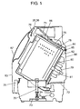
- Fig. 6 illustrates the internal structure of a conventional washing machine.
- This washing machine has a vibration-proofing structure for preventing transmission of vibration associated with drum rotation to casing 1.
- suspension 3 in casing 1 has the vibration-proofing structure so as to support washing tub 2 and absorb its vibration by suspending washing tub 2 from above.
- damper 4 supports washing tub 2 from beneath so as to damp vibrations.
- Cylindrical drum 5 with a bottom is rotatably supported in washing tub 2.
- Motor 7 is provided on an external bottom of washing tub 2, and rotation of motor 7 is transmitted to drum 5 through motor pulley 8, belt 9, driving pulley 6, and so on.
- a series of steps including washing, rinsing, and spin-drying (dehydrating) are executed by rotating drum 5.
- Acceleration sensor 10 is fixed to washing tub 2. When washing tub 2 vibrates and acceleration is applied to acceleration sensor 10, an oscillator inside acceleration sensor 10 oscillates and converts this displacement to an electrical signal. This electrical signal is transmitted to a controller (not illustrated), and is used to control the vibration. Lead switch 14 is also mounted on washing tub 2. Lead switch 14 turns on and off by magnet 15 attached to driving pulley 6. These ON and OFF signals are transmitted to the controller, and are also used for typically controlling the rotation.
- the vibration-proofing structure oscillatably supports washing tub 2 and absorbs unbalanced vibrations caused by laundry in drum 5 becoming unevenly distributed during the spin-drying step. Transmission of vibration to casing 1 is thus preventable. However, if the laundry becomes more than usually piled on one side, washing tub 2 may generate abnormal vibration.
- the controller reduces the rotating speed of drum 5 or stops the spin-drying operation and supplies more water to rebalance the laundry, in response to vibration of washing tub 2 detected by acceleration sensor 10.
- washing tub 2 may be excessively shaken when transporting or delivering the washing machine because washing tub 2 is oscillatably supported inside casing 1.
- washing tub 2 or components attached to washing tub 2 may collide with the inner wall of casing 1 or other components attached inside casing 1, causing damage.
- transport fixture 16 is attached between casing 1 and washing tub 2 by fixing bolt 17 before transportation. Washing tub 2 is therefore anchored to avoid movement during transportation. On installing the washing machine, fixing bolt 17 and transport fixture 16 are removed to release washing tub 2.
- US 6,032,494 discloses a drum type drying/washing machine in which the drum is rotated at an almost maximum rotational rate at which, in a low speed rotation, materials to be processed can roll over in the drum.
- the drum can be rotated at a rotational rate above which, in the low speed rotation, the materials to be processed as a whole stick to the inner peripheral wall of the drum. Further, the drum is accelerated to a high speed rotation only when an output from an unbalance detecting device is a predetermined level or less.
- the present invention offers a washing machine that prevents failure due to abnormal vibration during washing and spin-dry by detecting whether or not a washing tub is anchored with respect to a casing early on in the washing step.
- the washing machine of the present invention includes a casing, a washing tub, a drum, an acceleration sensor, an acceleration detector, a displacement calculator, a motor, a rotating speed detector, and a controller.
- the washing tub is oscillatably and resiliently supported inside the casing.
- the cylindrical drum with a bottom has an axis of rotation, and is disposed inside the washing tub to hold laundry.
- the acceleration sensor attached to the washing tub can detect acceleration of vibration of the washing tub.
- the acceleration detector detects an acceleration output from the acceleration sensor.
- the displacement calculator calculates the acceleration output of the washing tub output from the acceleration detector to output a displacement.
- the motor rotates (drives) the drum.
- the rotating speed detector detects a rotation speed of the motor.
- the controller controls the rotation of the motor based on the detected output from the rotating speed detector, and controls a washing step and a step of detecting the quantity of laundry before the washing step.
- the controller also detects a state that the washing tub is anchored with respect to the casing. More specifically, the controller makes the motor generate a predetermined acceleration torque during a step of detecting the laundry quantity. The drum rotation is then increased to a predetermined rotating speed. Rotation at this predetermined rotating speed is retained for a predetermined time. While the rotation continues, a calculation result output from the displacement calculator is compared with a preset reference value. If the calculation result is smaller than the reference value, a state that the washing tub is anchored with respect to the casing is detected.
- Fig. 1 is a sectional view illustrating a structure of a drum-type washing machine during transportation in the exemplary embodiment of the present invention.
- Fig. 2 is a block diagram of a control circuit of the drum-type washing machine.
- This washing machine includes casing 83, washing tub 82, drum 78, acceleration sensor 88, acceleration detector 39, displacement calculator 40, motor 81, rotating speed detector 33, and controller 31.
- Washing tub 82 is oscillatably and resiliently supported inside casing 83.
- Cylindrical drum 78 with a bottom has rotation axis 79 that extends horizontally or obliquely, and is disposed inside washing tub 82 so as to hold laundry.
- Acceleration sensor 88 is fixed to washing tub 82, and detects a vibration component in multiple directions. In other words, acceleration sensor 88 can detect acceleration of vibration of washing tub 82. Acceleration detector 39 detects an acceleration output from acceleration sensor 88. Displacement calculator 40 calculates the acceleration output in a front-back direction or top-bottom direction of washing tub 82, and outputs a displacement in the front-back direction or top-bottom direction.
- Motor 81 rotates drum 78.
- Rotating speed detector 33 detects the speed of rotation (number of revolutions per unit time) of motor 81.
- Controller 31 controls the rotation of motor 81 based on a detection output of rotating speed detector 33. In other words, controller 31 controls a washing step, a rinsing step, a spin-drying step, and a step of detecting laundry quantity (fabric quantity) before the washing step. Controller 31 also detects whether or not washing tub 82 is anchored with respect to casing 83. In Fig. 2 , controller 31 includes acceleration detector 39, displacement calculator 40, and rotating speed detector 33. However, they may be provided separately.
- washing tub unit 76 includes washing tub 82, drum 78, bearing 80, and motor 81.
- Drum 78 is rotatably housed inside washing tub 82.
- Rotation axis 79 of drum 78 is supported by bearing 80 provided on a rear face of washing tub 82.
- Rotation axis 79 is connected to motor 81 for driving drum 78.
- Washing tub unit 76 is disposed inside casing 83 with its axis center tilted. Vibration-proofing damper 70 attached to bottom 73 of casing 83 supports the weight of washing tub unit 76.
- First vibration-proofing spring 71 is provided between upper support clasp 75, which is fixed to a top part of washing tub 82, and the top face of casing 83.
- Second vibration-proofing spring 72 is provided between a bottom part of washing tub 82 and rear face 86 of casing 83.
- Vibration-proofing damper 70, first vibration-proofing spring 71, and second vibration-proofing spring 72 oscillatably and resiliently support washing tub 82 and absorb its vibration.
- Cover 87 is openably disposed on a left tilted face of casing 83. The user opens this cover 87 to load laundry into drum 78.
- Input setting part 35 and display panel 36 are provided above cover 87. Acceleration sensor 88 is fixed to an upper outer wall of washing tub 82. Controller 31 configured typically with a microcomputer establishes signal transmission with input setting part 35, display panel 36, and acceleration sensor 88; and also controls the rotation of motor 81. Input setting part 35 receives operation input by the user, and sends an input signal to controller 31. Display panel 36 displays a content of input from input setting part 35 and a detection result of controller 31.
- Acceleration sensor 88 is typically configured with a semiconductor acceleration sensor. Acceleration sensor 88 is preferably configured with a sensor for multiple axes (two or three axes) typically in front-back, left- right, and top-bottom directions, instead of that for acceleration in a single direction. Vibration of washing tub unit 76 is not always limited to one direction. Therefore, movement of washing tub 82 is more accurately detectable by employing an acceleration sensor for multiple axes.
- Transport fixture 84 for preventing shaking of washing tub unit 76 during transportation of the washing machine is attached to upper support clasp 75 and rear face 86 of casing 83 by fixing bolt 85.
- upper support clasp 75 provided on the outer wall of washing tub 82 is a portion for attaching transport fixture 84 in order to anchor washing tub 82 to casing 83.
- Transport fixture 84 is needed only during transportation, and is removed together with fixing bolt 85 when the washing machine is installed.
- rectifier 21 rectifies AC electric power of commercial power 20.
- a smoothing circuit configured with choke coil 22 and smoothing capacitor 23, smoothes rectified power and supplies DC electric power to inverter circuit 24.
- Inverter circuit 24 rotates motor 81 using this DC power as driving electric power.
- Controller 31 controls the rotation of motor 81 based on an operating instruction input from input setting part 35 and information on operation status detected by a range of detectors, including rotating speed detector 33 and acceleration sensor 88. Controller 31 also controls the operation of feed valve 27, drain valve 28, air blower 12, and heater 29 by using load driver 26. In addition, controller 31 sends a signal to display panel 36 for displaying the operation status and control state so that the user becomes informed.
- Motor 81 includes a stator having three-phase coils 7a, 7b, and 7c; a rotor (not illustrated) having dipole permanent magnet; and position detecting elements 30a, 30b, and 30c.
- motor 81 is, for example, configured with a DC brushless motor, and is rotated and controlled by PWM(Pulse Width Modulation)-controlled inverter circuit 24 configured with switching elements 24a to 24f. Accordingly, the rotating speed of motor 81 is variable.
- Rotor position detection signals detected by position detecting elements 30a, 30b, and 30c are input to controller 31. Based on these rotor position detection signals, controller 31 controls ON and OFF states of switching elements 24a to 24f by PWM control, using diving circuit 32. Through this control, controller 31 controls a current flow to three-phase coils 7a, 7b, and 7c of the stator so as to rotate motor 81 at a predetermined rotating speed.
- Rotating speed detector 33 detects a time cycle of one of signals of position detecting elements 30a, 30b, and 30c corresponding to the change the one of signals, and calculates a rotating speed of motor 81 from this time cycle.
- laundly-quantity detector 34 can detect the quantity of laundry (fabric quantity) loaded to drum 78 based on a detected rotating speed by supplying the detection output of rotating speed detector 33 to laundry-quantity detector 34. More specifically, laundry-quantity detector 34 detects the laundry quantity loaded to drum 78 by using power (load generated in motor 81 when the rotating speed increases) applied to motor 81, the detection output of rotating speed detector 33, and the time needed for changing rotating speed. Further details are described later.
- the rotating speed of drum 78 in the following description refers to that obtained based on the detection output from rotating speed detector 33.
- Acceleration sensor 88 fixed to washing tub 82 detects acceleration of washing tub 82 in multiple directions of top-bottom and front-back.
- Acceleration detector 39 detects a digital signal or an analog signal from acceleration sensor 88. For example, acceleration detector 39 samples acceleration at 160 Hz in a period of the laundry-quantity detection step.
- Displacement calculator 40 calculates this acceleration data, and figures out displacement in the top-bottom and front-back directions. Controller 31 detects presence of abnormal vibration based on displacement data of washing tub 82 calculated in this way, so as to detect whether or not transport fixture 84 is in place.
- FIG. 3 and 4 illustrate the operation for detecting laundry quantity in the drum-type washing machine in Fig. 1 .
- a horizontal axis indicates an elapse of time
- a vertical axis indicates the rotating speed of drum 78.
- controller 31 gives an instruction for starting the laundry-quantity detection step before starting the washing operation
- motor 81 starts to rotate.
- controller 31 makes motor 81 generate acceleration torque T1 after a predetermined time passes or after reaching predetermined rotating speed N1. Then, the rotating speed is increased by ⁇ N1 in time t1 to reach predetermined rotating speed N2 (first detection step).
- Predetermined rotating speed N1 is a low rotating speed immediately after motor 81 starts.
- Predetermined rotating speed N2 is a rotating speed not greater than a primary resonance frequency of washing tub unit 72, which is a vibrating system in Fig. 1 .
- a reason for setting maximum rotating speed N2 of the drum to a rotating speed not greater than the primary resonance frequency of washing tub unit 76 is described later.
- controller 31 controls motor 81 to retain rotating speed N2 for ts seconds without reducing the rotating speed. Then, while the rotating speed is stably retained at N2, acceleration sensor 88 executes the step of detecting presence of transport fixture 84.
- An inertia moment in the vibrating system such as drum 78, changes corresponding to the quantity of laundry loaded in drum 78. This may cause variation in period of time until the rotating speed reaches N2, or unstable rotating speed. Controller 31 retains rotating speed at N2 for ts seconds so as to reduce such variations. Detection variations in acceleration detected by acceleration sensor 88 thus becomes small.
- the rotating speed can be ideally retained at N2 when the inertia moment of the vibrating system, such as drum 78, is small.
- the inertia moment of the vibrating system, such as drum 78 is large, the rotating speed overshoots after reaching N2, and thus the rotating speed may become slightly higher than N2. This overshooting differs by the quantity and texture of laundry.
- controller 31 immediately corrects the rotating speed to N2 by the rotating speed correction control. Then, in the next ts seconds, acceleration sensor 88 executes the step of detecting presence of transport fixture 84.
- a setting of 1 to 3 seconds for ts seconds is normally sufficient for ensuring correct detection, although it also depends on a capacity of each washing machine.
- controller 31 After completing the step of detecting presence of transport fixture 84, controller 31 reduces the rotating speed of drum 78. Then, decelerating torque T2 is generated by motor 81 in the inertia rotation so as to reduce the rotating speed for ⁇ N2 from predetermined rotating speed N3 in time t2 so that the rotating speed of motor 81 reaches predetermined N4 (second detection step).
- decelerating torque T2 is generated by motor 81 in the inertia rotation so as to reduce the rotating speed for ⁇ N2 from predetermined rotating speed N3 in time t2 so that the rotating speed of motor 81 reaches predetermined N4 (second detection step).
- N4 predetermined N4
- t1 is calculated based on a load applied to motor 81 in increasing the rotating speed in the first detection step
- t2 is calculated based on reduction of the rotating speed in the second detection step.
- Laundry-quantity detector 34 calculates the quantity of loaded laundry based on a predetermined table using t1 and t2.
- controller 31 detects acceleration caused by shaking of washing tub 82 so as to detect presence of transport fixture 84.
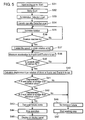
- FIG. 5 is a flow chart illustrating a transport fixture detection method for the drum-type washing machine shown in Fig. 1 .
- Acceleration sensor 88 outputs an acceleration signal in at least the top-bottom and front-back directions of washing tub unit 76, and acceleration detector 39 detects this output.
- controller 31 starts the laundry-quantity detection step (S34). In other words, controller 31 drives motor 81 to increase the rotating speed of drum 78 from N1 by using predetermined torque T1 such that the rotating speed reaches predetermined rotating speed N2, which is faster by ⁇ N1 (S35).
- controller 31 When the rotating speed of drum 78 reaches N2, controller 31 immediately controls the operation to retain the rotating speed of drum 78 at N2 (S37).
- acceleration detector 39 measures the acceleration signal in the front-back direction (X-axis) and the top-bottom direction (Z-axis) (S38). The acceleration signal at rotating speed N2 is measured for ts seconds (S39).
- displacement calculator 40 calculates the acceleration signal in the X-axis direction and Z-axis direction, using four arithmetical operations, so as to figure out amount of displacement in the X-axis direction and Z-axis direction per rotation of drum 78 (S40).
- Controller 31 compares the displacement of washing tub 82 in the X-axis direction with a preset reference value (S41). If the displacement in the X-axis direction is smaller than the reference value, controller 31 next compares displacement of washing tub 82 in the Z-axis direction with a preset reference value (S42). If the displacement in the Z-axis direction is also smaller than the reference value, controller 31 determines that washing tub 82 is anchored with respect to casing 83. In other words, controller 31 determines that the presence of transport fixture 84 is holding back vibration that should be generated under normal conditions (S43), and stops any further operations (S44). Controller 31 may also display the information that washing tub 82 is anchored with respect to casing 83 on display panel 36 (S45).
- controller 31 determines that washing tub 82 is movable in an oscillatable manner. In other words, controller 31 determines that there is no transport fixture 84 (S46), and proceeds to the next washing step (S47).
- controller 31 makes motor 81 generate predetermined acceleration torque T1 early on in detecting the laundry quantity.
- This torque T1 increases the rotation of drum 78 to rotating speed N2 that is not greater than the primary resonance frequency of washing tub unit 76, which is the vibrating system including washing tub 82.
- controller 31 retains the rotation at rotating speed N2 for time ts.
- an acceleration signal is detected so as to calculate displacement in the front-back direction and top-bottom direction by displacement calculator 40.
- calculated displacement (arithmetical result) is compared with the reference value. If the arithmetical result is smaller than the reference value, a state that washing tub 82 is anchored with respect to casing 83 is detected. In this way, controller 31 detects whether or not washing tub 82 is anchored with respect to casing 83.
- the presence of transport fixture 84 is thus accurately detectable by directly detecting amplitude of vibration of washing tub 82 with the above structure.
- the presence of transport fixture 84 is determined early on in the operation of the washing machine at the step of detecting laundry quantity. This prevents occurrence of abnormal vibrations during the washing and spin-drying steps.
- display of an abnormal state readily notifies the user of the situation.
- a buzzer or voice guidance may also be provided. In other words, any notifier for notifying a detection result of controller 31 may be provided.
- the setup for this detection process does not require any special structure.
- a conventional vibration sensor or laundry-quantity detection structure already in practical use can be applied. Accordingly, the setup for this detection process can be put into practical use at low cost.
- Maximum rotating speed N2 of drum 78 on detecting laundry quantity or the presence of transport fixture 84 is set to not greater than the primary resonance frequency of washing tub 82. This avoids the generation of a high amount of energy, although washing tub 82 shakes during detection. Therefore, the laundry quantity or the presence of transport fixture 84 is detectable without abnormal vibration or noise being generated, even if transport fixture 84 is not detached.
- displacement in the X-axis direction and Z-axis direction is calculated and then compared with the reference values.
- vibration in the left-light direction Y-axis direction
- vibration in the left-light direction may be detected to calculate displacement in the Y-axis direction and used for determination.
- one or two displacements in the X-axis direction, Y-axis direction, or Z-axis direction may be used for determination.
- the quantity of laundry in drum 78 is detected at both increasing and decreasing the rotating speed.
- the laundry quantity may also be detected only at either one.
- the present invention is not limited to this structure. Even if the axis of rotation of drum 78 is vertical, the present invention is applicable if washing tub 82 housing drum 78 is anchored during transportation.
- washing tub 82 is anchored to casing 83 using transport fixture 84.
- the present invention is not limited to this structure.
- the present invention is also applicable to other structures for anchoring washing tub 82, including a structure in which packing material is inserted inside casing 83.
- the erroneous leaving in place of transport fixture 84 used during transport and delivery of the washing machine can be accurately detected, and thus failure caused by abnormal vibration during washing or spin-drying steps can be prevented.
- the present invention is thus effectively applicable to washing machines for both household and industrial use.
Landscapes
- Engineering & Computer Science (AREA)
- Textile Engineering (AREA)
- Control Of Washing Machine And Dryer (AREA)
- Main Body Construction Of Washing Machines And Laundry Dryers (AREA)
- Centrifugal Separators (AREA)
Applications Claiming Priority (1)
| Application Number | Priority Date | Filing Date | Title |
|---|---|---|---|
| JP2008240482A JP4640476B2 (ja) | 2008-09-19 | 2008-09-19 | 洗濯機 |
Publications (2)
| Publication Number | Publication Date |
|---|---|
| EP2175061A1 EP2175061A1 (en) | 2010-04-14 |
| EP2175061B1 true EP2175061B1 (en) | 2011-02-23 |
Family
ID=40874626
Family Applications (1)
| Application Number | Title | Priority Date | Filing Date |
|---|---|---|---|
| EP09156974A Not-in-force EP2175061B1 (en) | 2008-09-19 | 2009-03-31 | Washing machine |
Country Status (7)
| Country | Link |
|---|---|
| EP (1) | EP2175061B1 (ja) |
| JP (1) | JP4640476B2 (ja) |
| CN (1) | CN101676470B (ja) |
| AT (1) | ATE499473T1 (ja) |
| DE (1) | DE602009000781D1 (ja) |
| RU (1) | RU2407832C1 (ja) |
| TW (1) | TW201013002A (ja) |
Cited By (2)
| Publication number | Priority date | Publication date | Assignee | Title |
|---|---|---|---|---|
| CN102953255A (zh) * | 2012-10-26 | 2013-03-06 | 无锡飞翎电子有限公司 | 洗衣机及洗衣机脱水控制方法和系统 |
| US8863558B2 (en) | 2012-07-10 | 2014-10-21 | Whirlpool Corporation | Laundry treating appliance and method of operation |
Families Citing this family (17)
| Publication number | Priority date | Publication date | Assignee | Title |
|---|---|---|---|---|
| DE102010001845A1 (de) * | 2010-02-11 | 2011-08-11 | BSH Bosch und Siemens Hausgeräte GmbH, 81739 | Einrichtung zur Überwachung einer im Betrieb schwingenden Vorrichtung eines Haushaltsgeräts, Haushaltsgerät zur Pflege von Wäschestücken sowie Verfahren zum Betreiben eines Haushaltsgeräts |
| JP5678275B2 (ja) * | 2011-04-04 | 2015-02-25 | パナソニックIpマネジメント株式会社 | 洗濯機 |
| EP2508666B1 (de) * | 2011-04-06 | 2014-04-30 | Miele & Cie. KG | Waschmaschine mit einem Laugenbehälter und einer Erfassungseinrichtung |
| JP2012223489A (ja) * | 2011-04-22 | 2012-11-15 | Toshiba Corp | 洗濯機 |
| JP5753980B2 (ja) * | 2011-09-29 | 2015-07-22 | パナソニックIpマネジメント株式会社 | ドラム式洗濯機 |
| DE102011084267A1 (de) * | 2011-10-11 | 2013-04-11 | BSH Bosch und Siemens Hausgeräte GmbH | Wäschebehandlungsgerät mit Transportsicherung und zugeordneter Überwachungseinrichtung sowie dafür geeignetes Verfahren |
| DE102011089624A1 (de) * | 2011-12-22 | 2013-06-27 | BSH Bosch und Siemens Hausgeräte GmbH | Haushaltsgerät zur Pflege von Wäschestücken sowie Verfahren zum Bestimmen eines Fehlerzustands einer Schwingvorrichtung eines Haushaltsgeräts |
| CN102660853A (zh) * | 2012-05-29 | 2012-09-12 | 南京乐金熊猫电器有限公司 | 一种滚桶洗衣机及用于滚桶洗衣机振动噪音改善的方法 |
| KR101980854B1 (ko) * | 2012-10-31 | 2019-05-22 | 삼성전자주식회사 | 세탁기 및 그 제어방법 |
| KR101555588B1 (ko) | 2012-10-31 | 2015-10-06 | 엘지전자 주식회사 | 세탁물 처리기기, 및 그 동작방법 |
| KR102206464B1 (ko) * | 2014-02-21 | 2021-01-21 | 엘지전자 주식회사 | 세탁기 및 세탁기의 제어방법 |
| CN105937135A (zh) * | 2016-06-30 | 2016-09-14 | 无锡小天鹅股份有限公司 | 洗衣机及其脱水振动检测装置和方法 |
| CN106436151A (zh) * | 2016-09-22 | 2017-02-22 | 惠而浦(中国)股份有限公司 | 基于3d位移传感器判断用户有无卸载运输螺栓的控制方法 |
| CN108957579B (zh) * | 2017-05-19 | 2022-05-27 | 重庆海尔滚筒洗衣机有限公司 | 洗涤设备包装螺栓是否拆除的检测方法及系统 |
| CN108118494B (zh) * | 2018-03-07 | 2020-07-10 | 江苏绿能家电科技有限公司 | 一种洗衣机的运输固定装置及其固定方法 |
| JP2020069260A (ja) * | 2018-11-01 | 2020-05-07 | 青島海爾洗衣机有限公司QingDao Haier Washing Machine Co.,Ltd. | 洗濯機 |
| CN114808365A (zh) * | 2021-01-21 | 2022-07-29 | 苏州三星电子有限公司 | 洗衣机运输螺栓未拆卸判定方法、洗衣机及可读存储介质 |
Family Cites Families (8)
| Publication number | Priority date | Publication date | Assignee | Title |
|---|---|---|---|---|
| DE6950556U (de) * | 1969-12-19 | 1971-05-27 | Siemens Elektrogeraete Gmbh | Transportsicherung fuer ein in einem gehaeuse elastisch abgestuetztes waschaggregat einer trommelwaschmaschine. |
| US5887456A (en) | 1995-08-30 | 1999-03-30 | Sharp Kabushiki Kaisha | Drum type drying/washing machine |
| JP3914514B2 (ja) * | 2003-05-21 | 2007-05-16 | 日立アプライアンス株式会社 | 洗濯機 |
| JP2005026932A (ja) * | 2003-06-30 | 2005-01-27 | Kyocera Mita Corp | 固定手段外し忘れ防止構造 |
| CN1611662A (zh) * | 2003-10-30 | 2005-05-04 | 乐金电子(天津)电器有限公司 | 滚筒洗衣机的衣物量和偏心值的检测装置及其方法 |
| JP2007167262A (ja) * | 2005-12-21 | 2007-07-05 | Sanyo Electric Co Ltd | ドラム式洗濯機 |
| JP4867631B2 (ja) * | 2006-12-08 | 2012-02-01 | パナソニック株式会社 | 洗濯機 |
| JP4421638B2 (ja) * | 2007-07-30 | 2010-02-24 | 株式会社東芝 | ドラム式洗濯機 |
-
2008
- 2008-09-19 JP JP2008240482A patent/JP4640476B2/ja not_active Expired - Fee Related
-
2009
- 2009-02-26 TW TW098106148A patent/TW201013002A/zh not_active IP Right Cessation
- 2009-03-31 EP EP09156974A patent/EP2175061B1/en not_active Not-in-force
- 2009-03-31 AT AT09156974T patent/ATE499473T1/de not_active IP Right Cessation
- 2009-03-31 DE DE602009000781T patent/DE602009000781D1/de active Active
- 2009-04-15 CN CN2009101349485A patent/CN101676470B/zh not_active Expired - Fee Related
- 2009-09-18 RU RU2009134973/12A patent/RU2407832C1/ru not_active IP Right Cessation
Cited By (3)
| Publication number | Priority date | Publication date | Assignee | Title |
|---|---|---|---|---|
| US8863558B2 (en) | 2012-07-10 | 2014-10-21 | Whirlpool Corporation | Laundry treating appliance and method of operation |
| CN102953255A (zh) * | 2012-10-26 | 2013-03-06 | 无锡飞翎电子有限公司 | 洗衣机及洗衣机脱水控制方法和系统 |
| CN102953255B (zh) * | 2012-10-26 | 2015-03-25 | 无锡飞翎电子有限公司 | 洗衣机及洗衣机脱水控制方法和系统 |
Also Published As
| Publication number | Publication date |
|---|---|
| CN101676470A (zh) | 2010-03-24 |
| JP4640476B2 (ja) | 2011-03-02 |
| CN101676470B (zh) | 2011-10-26 |
| TWI372804B (ja) | 2012-09-21 |
| TW201013002A (en) | 2010-04-01 |
| EP2175061A1 (en) | 2010-04-14 |
| JP2010069044A (ja) | 2010-04-02 |
| ATE499473T1 (de) | 2011-03-15 |
| DE602009000781D1 (de) | 2011-04-07 |
| RU2407832C1 (ru) | 2010-12-27 |
Similar Documents
| Publication | Publication Date | Title |
|---|---|---|
| EP2175061B1 (en) | Washing machine | |
| EP2103726B1 (en) | Drum type washing machine | |
| US10214843B2 (en) | Control method of washing machine | |
| JP2010057848A (ja) | 洗濯機 | |
| JP5678275B2 (ja) | 洗濯機 | |
| JP2011200273A (ja) | 洗濯機 | |
| JP4835673B2 (ja) | 洗濯機 | |
| JP2011062334A (ja) | ドラム式洗濯機 | |
| JPH05154275A (ja) | ドラム式洗濯機 | |
| JP5326842B2 (ja) | 洗濯機 | |
| JP5753980B2 (ja) | ドラム式洗濯機 | |
| JP2013052062A (ja) | ドラム式洗濯機 | |
| JP2011152250A (ja) | ドラム式洗濯機 | |
| JP2010125250A (ja) | ドラム式洗濯機 | |
| JP4894878B2 (ja) | ドラム式洗濯機 | |
| JP4935764B2 (ja) | ドラム式洗濯機 | |
| JPH0515689A (ja) | ドラム式洗濯機 | |
| JP2009297123A (ja) | ドラム式洗濯機 | |
| JP2009189537A (ja) | 洗濯機 | |
| JP2011104141A (ja) | 洗濯機 | |
| JP2016146983A (ja) | 洗濯機 | |
| JP6326634B2 (ja) | 洗濯機 | |
| JP2014064740A (ja) | ドラム式洗濯機 | |
| JP2011167273A (ja) | ドラム式洗濯機 | |
| JP4888478B2 (ja) | ドラム式洗濯機 |
Legal Events
| Date | Code | Title | Description |
|---|---|---|---|
| PUAI | Public reference made under article 153(3) epc to a published international application that has entered the european phase |
Free format text: ORIGINAL CODE: 0009012 |
|
| AK | Designated contracting states |
Kind code of ref document: A1 Designated state(s): AT BE BG CH CY CZ DE DK EE ES FI FR GB GR HR HU IE IS IT LI LT LU LV MC MK MT NL NO PL PT RO SE SI SK TR |
|
| AX | Request for extension of the european patent |
Extension state: AL BA RS |
|
| 17P | Request for examination filed |
Effective date: 20100323 |
|
| 17Q | First examination report despatched |
Effective date: 20100416 |
|
| GRAP | Despatch of communication of intention to grant a patent |
Free format text: ORIGINAL CODE: EPIDOSNIGR1 |
|
| RIC1 | Information provided on ipc code assigned before grant |
Ipc: D06F 37/20 20060101AFI20100924BHEP |
|
| AKX | Designation fees paid |
Designated state(s): AT BE BG CH CY CZ DE DK EE ES FI FR GB GR HR HU IE IS IT LI LT LU LV MC MK MT NL NO PL PT RO SE SI SK TR |
|
| GRAS | Grant fee paid |
Free format text: ORIGINAL CODE: EPIDOSNIGR3 |
|
| GRAA | (expected) grant |
Free format text: ORIGINAL CODE: 0009210 |
|
| AK | Designated contracting states |
Kind code of ref document: B1 Designated state(s): AT BE BG CH CY CZ DE DK EE ES FI FR GB GR HR HU IE IS IT LI LT LU LV MC MK MT NL NO PL PT RO SE SI SK TR |
|
| REG | Reference to a national code |
Ref country code: GB Ref legal event code: FG4D |
|
| REG | Reference to a national code |
Ref country code: CH Ref legal event code: EP |
|
| REG | Reference to a national code |
Ref country code: IE Ref legal event code: FG4D |
|
| REF | Corresponds to: |
Ref document number: 602009000781 Country of ref document: DE Date of ref document: 20110407 Kind code of ref document: P |
|
| REG | Reference to a national code |
Ref country code: DE Ref legal event code: R096 Ref document number: 602009000781 Country of ref document: DE Effective date: 20110407 |
|
| REG | Reference to a national code |
Ref country code: NL Ref legal event code: VDEP Effective date: 20110223 |
|
| LTIE | Lt: invalidation of european patent or patent extension |
Effective date: 20110223 |
|
| PG25 | Lapsed in a contracting state [announced via postgrant information from national office to epo] |
Ref country code: PT Free format text: LAPSE BECAUSE OF FAILURE TO SUBMIT A TRANSLATION OF THE DESCRIPTION OR TO PAY THE FEE WITHIN THE PRESCRIBED TIME-LIMIT Effective date: 20110623 Ref country code: LT Free format text: LAPSE BECAUSE OF FAILURE TO SUBMIT A TRANSLATION OF THE DESCRIPTION OR TO PAY THE FEE WITHIN THE PRESCRIBED TIME-LIMIT Effective date: 20110223 Ref country code: HR Free format text: LAPSE BECAUSE OF FAILURE TO SUBMIT A TRANSLATION OF THE DESCRIPTION OR TO PAY THE FEE WITHIN THE PRESCRIBED TIME-LIMIT Effective date: 20110223 Ref country code: ES Free format text: LAPSE BECAUSE OF FAILURE TO SUBMIT A TRANSLATION OF THE DESCRIPTION OR TO PAY THE FEE WITHIN THE PRESCRIBED TIME-LIMIT Effective date: 20110603 Ref country code: LV Free format text: LAPSE BECAUSE OF FAILURE TO SUBMIT A TRANSLATION OF THE DESCRIPTION OR TO PAY THE FEE WITHIN THE PRESCRIBED TIME-LIMIT Effective date: 20110223 Ref country code: SE Free format text: LAPSE BECAUSE OF FAILURE TO SUBMIT A TRANSLATION OF THE DESCRIPTION OR TO PAY THE FEE WITHIN THE PRESCRIBED TIME-LIMIT Effective date: 20110223 Ref country code: GR Free format text: LAPSE BECAUSE OF FAILURE TO SUBMIT A TRANSLATION OF THE DESCRIPTION OR TO PAY THE FEE WITHIN THE PRESCRIBED TIME-LIMIT Effective date: 20110524 Ref country code: NO Free format text: LAPSE BECAUSE OF FAILURE TO SUBMIT A TRANSLATION OF THE DESCRIPTION OR TO PAY THE FEE WITHIN THE PRESCRIBED TIME-LIMIT Effective date: 20110523 |
|
| PG25 | Lapsed in a contracting state [announced via postgrant information from national office to epo] |
Ref country code: AT Free format text: LAPSE BECAUSE OF FAILURE TO SUBMIT A TRANSLATION OF THE DESCRIPTION OR TO PAY THE FEE WITHIN THE PRESCRIBED TIME-LIMIT Effective date: 20110223 Ref country code: SI Free format text: LAPSE BECAUSE OF FAILURE TO SUBMIT A TRANSLATION OF THE DESCRIPTION OR TO PAY THE FEE WITHIN THE PRESCRIBED TIME-LIMIT Effective date: 20110223 Ref country code: NL Free format text: LAPSE BECAUSE OF FAILURE TO SUBMIT A TRANSLATION OF THE DESCRIPTION OR TO PAY THE FEE WITHIN THE PRESCRIBED TIME-LIMIT Effective date: 20110223 Ref country code: CY Free format text: LAPSE BECAUSE OF FAILURE TO SUBMIT A TRANSLATION OF THE DESCRIPTION OR TO PAY THE FEE WITHIN THE PRESCRIBED TIME-LIMIT Effective date: 20110223 Ref country code: BE Free format text: LAPSE BECAUSE OF FAILURE TO SUBMIT A TRANSLATION OF THE DESCRIPTION OR TO PAY THE FEE WITHIN THE PRESCRIBED TIME-LIMIT Effective date: 20110223 Ref country code: BG Free format text: LAPSE BECAUSE OF FAILURE TO SUBMIT A TRANSLATION OF THE DESCRIPTION OR TO PAY THE FEE WITHIN THE PRESCRIBED TIME-LIMIT Effective date: 20110523 Ref country code: FI Free format text: LAPSE BECAUSE OF FAILURE TO SUBMIT A TRANSLATION OF THE DESCRIPTION OR TO PAY THE FEE WITHIN THE PRESCRIBED TIME-LIMIT Effective date: 20110223 |
|
| PG25 | Lapsed in a contracting state [announced via postgrant information from national office to epo] |
Ref country code: DK Free format text: LAPSE BECAUSE OF FAILURE TO SUBMIT A TRANSLATION OF THE DESCRIPTION OR TO PAY THE FEE WITHIN THE PRESCRIBED TIME-LIMIT Effective date: 20110223 Ref country code: EE Free format text: LAPSE BECAUSE OF FAILURE TO SUBMIT A TRANSLATION OF THE DESCRIPTION OR TO PAY THE FEE WITHIN THE PRESCRIBED TIME-LIMIT Effective date: 20110223 Ref country code: MC Free format text: LAPSE BECAUSE OF NON-PAYMENT OF DUE FEES Effective date: 20110331 |
|
| PG25 | Lapsed in a contracting state [announced via postgrant information from national office to epo] |
Ref country code: CZ Free format text: LAPSE BECAUSE OF FAILURE TO SUBMIT A TRANSLATION OF THE DESCRIPTION OR TO PAY THE FEE WITHIN THE PRESCRIBED TIME-LIMIT Effective date: 20110223 Ref country code: RO Free format text: LAPSE BECAUSE OF FAILURE TO SUBMIT A TRANSLATION OF THE DESCRIPTION OR TO PAY THE FEE WITHIN THE PRESCRIBED TIME-LIMIT Effective date: 20110223 Ref country code: SK Free format text: LAPSE BECAUSE OF FAILURE TO SUBMIT A TRANSLATION OF THE DESCRIPTION OR TO PAY THE FEE WITHIN THE PRESCRIBED TIME-LIMIT Effective date: 20110223 |
|
| PG25 | Lapsed in a contracting state [announced via postgrant information from national office to epo] |
Ref country code: MT Free format text: LAPSE BECAUSE OF FAILURE TO SUBMIT A TRANSLATION OF THE DESCRIPTION OR TO PAY THE FEE WITHIN THE PRESCRIBED TIME-LIMIT Effective date: 20110223 |
|
| PLBE | No opposition filed within time limit |
Free format text: ORIGINAL CODE: 0009261 |
|
| STAA | Information on the status of an ep patent application or granted ep patent |
Free format text: STATUS: NO OPPOSITION FILED WITHIN TIME LIMIT |
|
| REG | Reference to a national code |
Ref country code: IE Ref legal event code: MM4A |
|
| PG25 | Lapsed in a contracting state [announced via postgrant information from national office to epo] |
Ref country code: IE Free format text: LAPSE BECAUSE OF NON-PAYMENT OF DUE FEES Effective date: 20110331 |
|
| 26N | No opposition filed |
Effective date: 20111124 |
|
| PG25 | Lapsed in a contracting state [announced via postgrant information from national office to epo] |
Ref country code: PL Free format text: LAPSE BECAUSE OF FAILURE TO SUBMIT A TRANSLATION OF THE DESCRIPTION OR TO PAY THE FEE WITHIN THE PRESCRIBED TIME-LIMIT Effective date: 20110223 |
|
| REG | Reference to a national code |
Ref country code: DE Ref legal event code: R097 Ref document number: 602009000781 Country of ref document: DE Effective date: 20111124 |
|
| PG25 | Lapsed in a contracting state [announced via postgrant information from national office to epo] |
Ref country code: MK Free format text: LAPSE BECAUSE OF FAILURE TO SUBMIT A TRANSLATION OF THE DESCRIPTION OR TO PAY THE FEE WITHIN THE PRESCRIBED TIME-LIMIT Effective date: 20110223 |
|
| PG25 | Lapsed in a contracting state [announced via postgrant information from national office to epo] |
Ref country code: LU Free format text: LAPSE BECAUSE OF NON-PAYMENT OF DUE FEES Effective date: 20110331 |
|
| PG25 | Lapsed in a contracting state [announced via postgrant information from national office to epo] |
Ref country code: IS Free format text: LAPSE BECAUSE OF FAILURE TO SUBMIT A TRANSLATION OF THE DESCRIPTION OR TO PAY THE FEE WITHIN THE PRESCRIBED TIME-LIMIT Effective date: 20110223 |
|
| PG25 | Lapsed in a contracting state [announced via postgrant information from national office to epo] |
Ref country code: TR Free format text: LAPSE BECAUSE OF FAILURE TO SUBMIT A TRANSLATION OF THE DESCRIPTION OR TO PAY THE FEE WITHIN THE PRESCRIBED TIME-LIMIT Effective date: 20110223 |
|
| PG25 | Lapsed in a contracting state [announced via postgrant information from national office to epo] |
Ref country code: HU Free format text: LAPSE BECAUSE OF FAILURE TO SUBMIT A TRANSLATION OF THE DESCRIPTION OR TO PAY THE FEE WITHIN THE PRESCRIBED TIME-LIMIT Effective date: 20110223 |
|
| REG | Reference to a national code |
Ref country code: CH Ref legal event code: PL |
|
| PG25 | Lapsed in a contracting state [announced via postgrant information from national office to epo] |
Ref country code: CH Free format text: LAPSE BECAUSE OF NON-PAYMENT OF DUE FEES Effective date: 20130331 Ref country code: LI Free format text: LAPSE BECAUSE OF NON-PAYMENT OF DUE FEES Effective date: 20130331 |
|
| REG | Reference to a national code |
Ref country code: FR Ref legal event code: PLFP Year of fee payment: 7 |
|
| PGFP | Annual fee paid to national office [announced via postgrant information from national office to epo] |
Ref country code: IT Payment date: 20150220 Year of fee payment: 7 Ref country code: DE Payment date: 20150324 Year of fee payment: 7 |
|
| PGFP | Annual fee paid to national office [announced via postgrant information from national office to epo] |
Ref country code: GB Payment date: 20150319 Year of fee payment: 7 Ref country code: FR Payment date: 20150309 Year of fee payment: 7 |
|
| REG | Reference to a national code |
Ref country code: DE Ref legal event code: R119 Ref document number: 602009000781 Country of ref document: DE |
|
| GBPC | Gb: european patent ceased through non-payment of renewal fee |
Effective date: 20160331 |
|
| REG | Reference to a national code |
Ref country code: FR Ref legal event code: ST Effective date: 20161130 |
|
| PG25 | Lapsed in a contracting state [announced via postgrant information from national office to epo] |
Ref country code: DE Free format text: LAPSE BECAUSE OF NON-PAYMENT OF DUE FEES Effective date: 20161001 Ref country code: GB Free format text: LAPSE BECAUSE OF NON-PAYMENT OF DUE FEES Effective date: 20160331 Ref country code: FR Free format text: LAPSE BECAUSE OF NON-PAYMENT OF DUE FEES Effective date: 20160331 |
|
| PG25 | Lapsed in a contracting state [announced via postgrant information from national office to epo] |
Ref country code: IT Free format text: LAPSE BECAUSE OF NON-PAYMENT OF DUE FEES Effective date: 20160331 |