EP2174825A2 - Energieerzeugungssystem zur Verwendung mit einem Fahrzeug - Google Patents
Energieerzeugungssystem zur Verwendung mit einem Fahrzeug Download PDFInfo
- Publication number
- EP2174825A2 EP2174825A2 EP08445034A EP08445034A EP2174825A2 EP 2174825 A2 EP2174825 A2 EP 2174825A2 EP 08445034 A EP08445034 A EP 08445034A EP 08445034 A EP08445034 A EP 08445034A EP 2174825 A2 EP2174825 A2 EP 2174825A2
- Authority
- EP
- European Patent Office
- Prior art keywords
- power generation
- solar panel
- generation system
- fuel cell
- moving mechanism
- Prior art date
- Legal status (The legal status is an assumption and is not a legal conclusion. Google has not performed a legal analysis and makes no representation as to the accuracy of the status listed.)
- Withdrawn
Links
- 238000010248 power generation Methods 0.000 title claims abstract description 113
- 239000000446 fuel Substances 0.000 claims abstract description 84
- 230000007246 mechanism Effects 0.000 claims abstract description 42
- 238000003860 storage Methods 0.000 claims abstract description 40
- 238000005868 electrolysis reaction Methods 0.000 claims abstract description 39
- 239000001257 hydrogen Substances 0.000 claims abstract description 35
- 229910052739 hydrogen Inorganic materials 0.000 claims abstract description 35
- UFHFLCQGNIYNRP-UHFFFAOYSA-N Hydrogen Chemical compound [H][H] UFHFLCQGNIYNRP-UHFFFAOYSA-N 0.000 claims abstract description 33
- XLYOFNOQVPJJNP-UHFFFAOYSA-N water Substances O XLYOFNOQVPJJNP-UHFFFAOYSA-N 0.000 claims abstract description 30
- QVGXLLKOCUKJST-UHFFFAOYSA-N atomic oxygen Chemical compound [O] QVGXLLKOCUKJST-UHFFFAOYSA-N 0.000 claims abstract description 20
- 239000001301 oxygen Substances 0.000 claims abstract description 20
- 229910052760 oxygen Inorganic materials 0.000 claims abstract description 20
- 238000006243 chemical reaction Methods 0.000 claims description 12
- 239000004065 semiconductor Substances 0.000 claims description 9
- 150000001875 compounds Chemical class 0.000 claims description 3
- 229910021420 polycrystalline silicon Inorganic materials 0.000 claims description 3
- 229920005591 polysilicon Polymers 0.000 claims description 3
- 230000010354 integration Effects 0.000 abstract description 5
- 238000007726 management method Methods 0.000 description 30
- 230000008859 change Effects 0.000 description 4
- 238000000034 method Methods 0.000 description 4
- LFQSCWFLJHTTHZ-UHFFFAOYSA-N Ethanol Chemical compound CCO LFQSCWFLJHTTHZ-UHFFFAOYSA-N 0.000 description 3
- OKKJLVBELUTLKV-UHFFFAOYSA-N Methanol Chemical compound OC OKKJLVBELUTLKV-UHFFFAOYSA-N 0.000 description 3
- 239000002131 composite material Substances 0.000 description 3
- 230000000694 effects Effects 0.000 description 3
- 239000005431 greenhouse gas Substances 0.000 description 3
- 229910000831 Steel Inorganic materials 0.000 description 2
- 230000005520 electrodynamics Effects 0.000 description 2
- 238000004146 energy storage Methods 0.000 description 2
- 238000005516 engineering process Methods 0.000 description 2
- 150000002431 hydrogen Chemical class 0.000 description 2
- VNWKTOKETHGBQD-UHFFFAOYSA-N methane Chemical compound C VNWKTOKETHGBQD-UHFFFAOYSA-N 0.000 description 2
- 230000009467 reduction Effects 0.000 description 2
- 239000010959 steel Substances 0.000 description 2
- 241000127225 Enceliopsis nudicaulis Species 0.000 description 1
- 241000282414 Homo sapiens Species 0.000 description 1
- XAGFODPZIPBFFR-UHFFFAOYSA-N aluminium Chemical compound [Al] XAGFODPZIPBFFR-UHFFFAOYSA-N 0.000 description 1
- 229910052782 aluminium Inorganic materials 0.000 description 1
- 239000000969 carrier Substances 0.000 description 1
- 238000001816 cooling Methods 0.000 description 1
- 239000010779 crude oil Substances 0.000 description 1
- 238000009826 distribution Methods 0.000 description 1
- 238000003487 electrochemical reaction Methods 0.000 description 1
- 230000002708 enhancing effect Effects 0.000 description 1
- 230000007613 environmental effect Effects 0.000 description 1
- 239000007789 gas Substances 0.000 description 1
- 238000010438 heat treatment Methods 0.000 description 1
- 238000009434 installation Methods 0.000 description 1
- 238000004519 manufacturing process Methods 0.000 description 1
- 239000003345 natural gas Substances 0.000 description 1
- 239000003921 oil Substances 0.000 description 1
- 238000005381 potential energy Methods 0.000 description 1
- 238000002360 preparation method Methods 0.000 description 1
- 230000008569 process Effects 0.000 description 1
- 230000001681 protective effect Effects 0.000 description 1
- 238000000629 steam reforming Methods 0.000 description 1
- 230000001502 supplementing effect Effects 0.000 description 1
Images


Classifications
-
- B—PERFORMING OPERATIONS; TRANSPORTING
- B60—VEHICLES IN GENERAL
- B60L—PROPULSION OF ELECTRICALLY-PROPELLED VEHICLES; SUPPLYING ELECTRIC POWER FOR AUXILIARY EQUIPMENT OF ELECTRICALLY-PROPELLED VEHICLES; ELECTRODYNAMIC BRAKE SYSTEMS FOR VEHICLES IN GENERAL; MAGNETIC SUSPENSION OR LEVITATION FOR VEHICLES; MONITORING OPERATING VARIABLES OF ELECTRICALLY-PROPELLED VEHICLES; ELECTRIC SAFETY DEVICES FOR ELECTRICALLY-PROPELLED VEHICLES
- B60L58/00—Methods or circuit arrangements for monitoring or controlling batteries or fuel cells, specially adapted for electric vehicles
- B60L58/30—Methods or circuit arrangements for monitoring or controlling batteries or fuel cells, specially adapted for electric vehicles for monitoring or controlling fuel cells
- B60L58/32—Methods or circuit arrangements for monitoring or controlling batteries or fuel cells, specially adapted for electric vehicles for monitoring or controlling fuel cells for controlling the temperature of fuel cells, e.g. by controlling the electric load
- B60L58/34—Methods or circuit arrangements for monitoring or controlling batteries or fuel cells, specially adapted for electric vehicles for monitoring or controlling fuel cells for controlling the temperature of fuel cells, e.g. by controlling the electric load by heating
-
- B—PERFORMING OPERATIONS; TRANSPORTING
- B60—VEHICLES IN GENERAL
- B60L—PROPULSION OF ELECTRICALLY-PROPELLED VEHICLES; SUPPLYING ELECTRIC POWER FOR AUXILIARY EQUIPMENT OF ELECTRICALLY-PROPELLED VEHICLES; ELECTRODYNAMIC BRAKE SYSTEMS FOR VEHICLES IN GENERAL; MAGNETIC SUSPENSION OR LEVITATION FOR VEHICLES; MONITORING OPERATING VARIABLES OF ELECTRICALLY-PROPELLED VEHICLES; ELECTRIC SAFETY DEVICES FOR ELECTRICALLY-PROPELLED VEHICLES
- B60L58/00—Methods or circuit arrangements for monitoring or controlling batteries or fuel cells, specially adapted for electric vehicles
- B60L58/30—Methods or circuit arrangements for monitoring or controlling batteries or fuel cells, specially adapted for electric vehicles for monitoring or controlling fuel cells
-
- B—PERFORMING OPERATIONS; TRANSPORTING
- B60—VEHICLES IN GENERAL
- B60L—PROPULSION OF ELECTRICALLY-PROPELLED VEHICLES; SUPPLYING ELECTRIC POWER FOR AUXILIARY EQUIPMENT OF ELECTRICALLY-PROPELLED VEHICLES; ELECTRODYNAMIC BRAKE SYSTEMS FOR VEHICLES IN GENERAL; MAGNETIC SUSPENSION OR LEVITATION FOR VEHICLES; MONITORING OPERATING VARIABLES OF ELECTRICALLY-PROPELLED VEHICLES; ELECTRIC SAFETY DEVICES FOR ELECTRICALLY-PROPELLED VEHICLES
- B60L58/00—Methods or circuit arrangements for monitoring or controlling batteries or fuel cells, specially adapted for electric vehicles
- B60L58/30—Methods or circuit arrangements for monitoring or controlling batteries or fuel cells, specially adapted for electric vehicles for monitoring or controlling fuel cells
- B60L58/32—Methods or circuit arrangements for monitoring or controlling batteries or fuel cells, specially adapted for electric vehicles for monitoring or controlling fuel cells for controlling the temperature of fuel cells, e.g. by controlling the electric load
- B60L58/33—Methods or circuit arrangements for monitoring or controlling batteries or fuel cells, specially adapted for electric vehicles for monitoring or controlling fuel cells for controlling the temperature of fuel cells, e.g. by controlling the electric load by cooling
-
- Y—GENERAL TAGGING OF NEW TECHNOLOGICAL DEVELOPMENTS; GENERAL TAGGING OF CROSS-SECTIONAL TECHNOLOGIES SPANNING OVER SEVERAL SECTIONS OF THE IPC; TECHNICAL SUBJECTS COVERED BY FORMER USPC CROSS-REFERENCE ART COLLECTIONS [XRACs] AND DIGESTS
- Y02—TECHNOLOGIES OR APPLICATIONS FOR MITIGATION OR ADAPTATION AGAINST CLIMATE CHANGE
- Y02E—REDUCTION OF GREENHOUSE GAS [GHG] EMISSIONS, RELATED TO ENERGY GENERATION, TRANSMISSION OR DISTRIBUTION
- Y02E10/00—Energy generation through renewable energy sources
- Y02E10/40—Solar thermal energy, e.g. solar towers
- Y02E10/46—Conversion of thermal power into mechanical power, e.g. Rankine, Stirling or solar thermal engines
-
- Y—GENERAL TAGGING OF NEW TECHNOLOGICAL DEVELOPMENTS; GENERAL TAGGING OF CROSS-SECTIONAL TECHNOLOGIES SPANNING OVER SEVERAL SECTIONS OF THE IPC; TECHNICAL SUBJECTS COVERED BY FORMER USPC CROSS-REFERENCE ART COLLECTIONS [XRACs] AND DIGESTS
- Y02—TECHNOLOGIES OR APPLICATIONS FOR MITIGATION OR ADAPTATION AGAINST CLIMATE CHANGE
- Y02T—CLIMATE CHANGE MITIGATION TECHNOLOGIES RELATED TO TRANSPORTATION
- Y02T10/00—Road transport of goods or passengers
- Y02T10/60—Other road transportation technologies with climate change mitigation effect
- Y02T10/7072—Electromobility specific charging systems or methods for batteries, ultracapacitors, supercapacitors or double-layer capacitors
-
- Y—GENERAL TAGGING OF NEW TECHNOLOGICAL DEVELOPMENTS; GENERAL TAGGING OF CROSS-SECTIONAL TECHNOLOGIES SPANNING OVER SEVERAL SECTIONS OF THE IPC; TECHNICAL SUBJECTS COVERED BY FORMER USPC CROSS-REFERENCE ART COLLECTIONS [XRACs] AND DIGESTS
- Y02—TECHNOLOGIES OR APPLICATIONS FOR MITIGATION OR ADAPTATION AGAINST CLIMATE CHANGE
- Y02T—CLIMATE CHANGE MITIGATION TECHNOLOGIES RELATED TO TRANSPORTATION
- Y02T90/00—Enabling technologies or technologies with a potential or indirect contribution to GHG emissions mitigation
- Y02T90/40—Application of hydrogen technology to transportation, e.g. using fuel cells
Definitions
- the present invention relates to power generation systems, and more particularly, to a mobile power generating and power supplying system characterized by integration of a photovoltaic cell and a fuel cell and configured for use with vehicles.
- Solar power generation is age-old technology. At the beginning, it features photo-thermal conversion. Now, it is focused on photoelectric conversion.
- Solar power generation facilities usually comprise lenses, mirrors, and solar tracking devices configured to focus sunlight, change a path of light propagation, and change the orientation of solar panels, respectively, so as to increase conversion efficiency.
- Solar tracking devices for use in power generation are found mostly in power generation facilities, for example, an array of solar panels. The purpose of solar tracking devices is to change the incident angle of an incoming light ray so as to maximize the efficiency of photoelectric conversion.
- Related patents abound. US4,205,657 discloses that, power generation or cooling is implemented by heating up water, using sunray focused by aluminum sheets with reflective curved surfaces.
- US4,350,837 discloses that light operable at a specific frequency is effectuated by focusing, reflection, and scattering and is configured for use in photovoltaic module-based power generation.
- US5,022,929 discloses that solar panels keep facing sunbeams squarely by means of a rotational platform capable of rotational movement with two degrees of freedom in the presence of link mechanism and hydraulic control.
- US5,983,634 discloses a power station equipped with movable reflection mirrors conducive to photothermal conversion and photoelectric conversion.
- US6,396,239 discloses a portable solar power generation device with a rotational axle adjustable for head-on exposure to sunshine.
- US7,240,674 disclose a one-axis solar tracker.
- Fuel cells are energy storage devices that entail supplementing fuel in order to allow electrochemical reaction to take place and produce energy.
- Fuels in wide use for the time being include hydrogen, methanol, ethanol, and natural gas. Among these, hydrogen fuel reacts with oxygen to produce water as a product. In hydrogen-based fuel cells, energy conversion brings relatively less pollution and no noise but is more efficient than general power generation technologies.
- development of fuel cells has its own predicament, namely availability of hydrogen fuel will be one of the important indices of the industrial applicability of hydrogen fuel as a potential energy source.
- Common methods for producing hydrogen include steam reforming, water electrolysis, etc. Emission of greenhouse gases to a certain extent will remain inevitable, provided that any existing method of power generation is in use. By contrast, where renewable energy is used in production of hydrogen, pollution caused by a process starting from energy retrieval and ending in energy release is markedly less than existing methods.
- the industrial sector is faced with an urgent issue, that is, developing a new power generating and power supplying system configured for use with vehicles, enhancement of power generation efficiency, resolution of recharging problems, and environmental protection.
- Solar power generation and fuel cells are the most promising alternative energy solutions for the time being.
- Studies on solar powered cars and fuel cell powered cars are to be still growing, and their forthcoming integration into a power generation system will keep their respective advantages, namely enhanced endurance and zero emission. Nevertheless, solar powered cars in use are not running at full speed, because they have only one distinguishing feature - solar panels attached to their body.
- a solar power generation system has 30% more output power when capable of solar tracking.
- a tracking-enabled solar power generation system coupled with solar panels attached to bodies and building integrated photovoltaics (BIPV) attached to windshields, further reduces the costs of a the electrodynamic system of a vehicle, or even turns the vehicle into a mobile power generation system whose outdoor users need not worry about power supply to the vehicle but enjoy the convenience of gaining access to power supply anytime and anywhere.
- the present invention provides a tracking-enabled solar power generation system for installation on a carrier, so to get in line with the trend toward using fuel cells in various carriers.
- the tracking-enabled solar power generation system performs solar powered electrolysis of water so as to produce hydrogen fuel required for fuel cells or store electric power in a storage battery, allowing the electric power to be supplied to a carrier and an external device.
- Another objective of the present invention is to provide a power generation system with enhanced efficiency of power generation.
- the present invention discloses a power generation system for use with vehicles, comprising: (a) a photovoltaic power generation device connected to a vehicle and comprises a movable platform, a platform moving mechanism, and a single-axis or two-axis solar tracking module, wherein the movable platform carries a photovoltaic power generation module equipped with a solar panel and converts light energy received by the solar panel into electrical energy, wherein the platform moving mechanism moves the movable platform, and wherein the solar tracking module is connected to the platform moving mechanism so as to determine the incident angle of light falling on the solar panel; and (b) a power management device comprising a storage battery and a power management unit, wherein the storage battery stores the converted electrical energy from the photovoltaic power generation module and providing electric power, wherein the power management unit is connected to the photovoltaic power generation device and the storage battery so as to prevent the storage battery from being over-recharged, over-discharged, or reversely recharged; (c)
- a power generation system for use with a vehicle comprises: (a) a photovoltaic power generation device for use with a vehicle, comprising a movable platform, a platform moving mechanism, and a solar tracking module, wherein the movable platform carries a photovoltaic power generation module equipped with a solar panel and converts light energy received by the solar panel into electrical energy, wherein the platform moving mechanism moves the movable platform, and wherein the solar tracking module is connected to the platform moving mechanism so as to determine the incident angle of light falling on the solar panel; and (b) a power management unit electrically connected to the photovoltaic power generation device and configured to control a power source provided to the vehicle by photovoltaic power generation module; and (c) a fuel cell device for receiving, through the power management unit, the electrical energy produced by the photovoltaic power generation module, the fuel cell device comprising: an electrolysis tank, a fuel storage unit, and a fuel cell, wherein the electrolysis tank is connected to the power management unit so
- FIG. 1A is a schematic view of a power generation system 100 for use with a vehicle according to the present invention.
- the power generation system 100 comprises a photovoltaic power generation device 110, a power management device 120, and a fuel cell device 130.
- the power management device 120 comprises a storage battery 122 and a power management unit 124.
- the storage battery 122 is configured to store the converted electrical energy from the photovoltaic power generation device 110 and provide electric power output.
- the power management unit 124 is connected to the photovoltaic power generation device 110 and the storage battery 122 so as to prevent the storage battery 122 from being over-recharged, over-discharged, or reversely recharged.
- the fuel cell device 130 is connected to the power management device 120 and configured to receive the electrical energy from the photovoltaic power generation device 110.
- the fuel cell device 130 comprises an electrolysis tank 132, a fuel storage unit 134, and a fuel cell 136.
- the electrolysis tank 132 is connected to the power management device 120 and configured to electrolyze water to produce hydrogen and oxygen.
- the fuel storage unit 134 is configured to receive and store the hydrogen and the oxygen produced in the electrolysis tank 132.
- the fuel cell 136 is connected to the fuel storage unit 134 so as to receive hydrogen fuel therefrom and generate electric power to be supplied to the vehicle as a power source thereof.
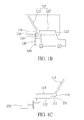
- FIG. 1B is a schematic view of the photovoltaic power generation device 110 of the present invention.
- the photovoltaic power generation device 110 of the power generation system 100 for use with a vehicle 140 is connected to the vehicle 140.
- the photovoltaic power generation device 110 comprises a movable platform 112, a platform moving mechanism 114, and a solar tracking module 116.
- the movable platform 112 is configured to carry a photovoltaic power generation module 115 equipped with a solar panel 113 so as to convert light energy received by the solar panel 113 into electrical energy.
- the platform moving mechanism 114 is configured to move the movable platform 112.
- the solar tracking module 116 is connected to the platform moving mechanism 114 so as to determine an incident angle of light falling on the solar panel.
- the solar panel of the present invention is selectively any appropriate panel, for example, a III-V group compound semiconductor solar panel, a polysilicon solar panel, an inorganic semiconductor solar panel, an organic semiconductor solar panel, or a dye-sensitized solar panel.
- the photovoltaic power generation module of the present invention can comprise a plurality of solar panels so as to receive more sunlight to be converted into more electrical energy.
- the movable platform 112 carries at least a first solar panel 113 and a second solar panel 113', wherein the platform moving mechanism 114 enables the first solar panel 113 to tilt and form an elevation angle relative to the second solar panel 113'.
- the solar tracking module 116 is connected to the platform moving mechanism 114 so as to determine an incident angle of light falling on the solar panel and determine, by means of the platform moving mechanism 114, such as the elevation angle of the first solar panel 113, the direction of incident light falling on the solar panel or increase the incident light with a view to enhancing the efficiency of power generation.
- the platform moving mechanism of the present invention comes in a single-axis form or a two-axis form and is fixed at any appropriate position of a vehicle (for example, a rack on top of the vehicle), so as to move the movable platform and the solar panel of the photovoltaic power generation module.
- the solar tracking module of the present invention is optionally installed with a GPS receiver or a solar sensor (not shown) as needed, so as to compute the orientation of the sun automatically. Given related data of the GPS receiver or the solar sensor, for example, a predicted position of the solar tracking module whereby a sunbeam is perpendicular to the solar panel to the greatest extent, the solar panel is moved to the predicted position before being finely adjusted by maximum power point tracking (MPPT), so as to speed up attaining the maximum conversion power.
- MPPT maximum power point tracking
- the power management device or an external power source supplies the platform moving mechanism and the solar tracking module with power.
- the power management device is electrically connected to the platform moving mechanism of the photovoltaic power generation device so as to move the movable platform.
- FIG. 1B illustrates a feasible way to implement a single-axis platform moving mechanism. Note that the illustration of FIG. 1B is not intended to limit the scope of the present invention.
- the photovoltaic power generation module 115 carried by a single-axis platform moving mechanism has a first solar panel 113 and a second solar panel 113'.
- the first solar panel 113 serves a protective capping function, capping the photovoltaic power generation module 115 in order to keep the sun-facing side of the photovoltaic power generation module 115 clean whenever the first solar panel 113 is not in use for sunlight capturing.
- the platform moving mechanism 114 carrying the photovoltaic power generation module 115 on a rack on top of the vehicle, the elevation angle of the first solar panel 113 of the photovoltaic power generation module 115 is altered as needed.
- the first solar panel 113 is lifted with a gear driven by the motor of the platform moving mechanism 114 until a theoretically desirable angle is attained. Furthermore, it is important to keep the elevation angle required for maximum output power according to variation in output power in practice.
- a single-axis or two-axis solar tracking module compares the consumption power of the platform moving mechanism with the power output of the photovoltaic power generation module as scheduled. For instance, where the photovoltaic power generation module in operation persistently generates power greater than the lower limit of modular conversion power (for example, 1W) but insufficient to keep the platform moving mechanism operating, the solar tracking module instructs the platform moving mechanism to stop solar tracking movement.
- the lower limit of modular conversion power for example, 1W
- the solar tracking module when it is cloudy, or as night falls, if the power output of the photovoltaic power generation module is persistently less than the lower limit of the modular conversion power within a specific period of time, the solar tracking module will instruct the platform moving mechanism to shut the first solar panel of the photovoltaic power generation module, or, in other words, to stop the operation of the photovoltaic power generation module.
- FIG. 1C is a schematic view of a specific, illustrative embodiment of a two-axis platform moving mechanism of the present invention
- an embodiment of a two-axis platform moving mechanism of the present invention has the following features.
- the first solar panel 113, the second solar panel 113', and the first motor 231 are installed on a carrier base 117 of the movable platform 112.
- the first motor 231 controls the elevation angle of the first solar panel 113.
- the second motor 232 drives the movable platform 112 and the second solar panel 113' to perform rotational movement horizontally by means of a gear train.
- implementation of the platform moving mechanism of the present invention is not limited to the described ways of moving or turning the solar panels in order to change the incident angle of sunlight.
- the specific embodiments are intended for description of several ways of integrating the platform moving mechanism into the solar panels of the photovoltaic power generation module, without limiting the scope of the present invention.
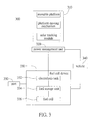
- a fuel cell device of the present invention comprises an electrolysis tank 210, a fuel storage unit 220, and a fuel cell 240. Electrodes 211 of the electrolysis tank 210 are electrically connected to the power management device (not shown) so as for hydrogen and oxygen to be produced by water electrolysis. The hydrogen and oxygen produced are delivered by a line 212 and a line 212', respectively, to steel bottle for storing hydrogen and oxygen or to the fuel storage unit 220 equipped with hydrogen-energy storing panels 214, for receipt and storage of the hydrogen and oxygen which originate from the electrolysis tank 210.
- Compressors 213 are installed between the electrolysis tank 210 and the fuel storage unit 220 as needed.
- the hydrogen and oxygen which originate from the electrolysis tank 210 are fed into the steel bottles or the hydrogen-energy storing panels 214 by the compressors 213, respectively, and then fed to the cathode and anode of the fuel cell 240 via a line 215 and a line 215', respectively.
- the hydrogen and oxygen react inside the fuel cell 240, and in consequence D.C. electric power and water are produced.
- the water which originates from the fuel cell 240 is delivered to a water tank 260 via a line 216.
- the water tank 260 is connected with the electrolysis tank 210 via a line 217, allowing water to be supplied to the electrolysis tank 210.
- the electrolysis tank 210 is provided with water from an external water source that adds the water to the electrolysis tank 210 or the water tank 260.
- the power generation system 300 comprises a photovoltaic power generation device 310, a power management unit 320, and a fuel cell device 330.
- the power management unit 320 is electrically connected to the photovoltaic power generation device 310 and configured to control a power source provided to the vehicle 340 by the photovoltaic power generation device 310.
- the fuel cell device 330 is connected to the power management unit 320 and configured to receive the electrical energy produced by the photovoltaic power generation device 310.
- the fuel cell device 330 comprises an electrolysis tank 332 connected with the power management unit 320 so as to produce hydrogen and oxygen by water electrolysis.
- the fuel storage unit 334 receives and stores the hydrogen and oxygen produced in the electrolysis tank 332.
- the fuel cell 336 is connected with the fuel storage unit 334 so as to receive hydrogen fuel from the fuel storage unit 334 and generate electric power to be supplied to the vehicle 340 as a power source thereof.
- the power generation system shown in FIG. 3 dispenses with a storage battery, and the converted electrical energy from the photovoltaic power generation device 310 is supplied to the platform moving mechanism, the solar tracking module, the fuel cell device, and any other external devices; hence, the power management unit not only controls a power source provided to the vehicle 340 by the photovoltaic power generation device 310 but also controls and determines whether water electrolysis is to take place in the electrolysis tank 332; for instance, the electrolysis tank is instructed to perform water electrolysis before the fuel storage unit reaches an upper limit of safe storage.
- a power management device or a power management unit is installed on and electrically connected to a vehicle so as to provide the vehicle with a power source.
- the power generation system which comprises a power management device or a power management unit, further comprises a port 150 (shown in FIG. 1 ) as needed.
- the port 150 is connected to the power management unit or the power management device so as to provide electrical connection with an external device.
- the power generation system further comprises a port 350 (shown in FIG. 3 but not limited thereto) connected to the fuel cell device 330, so as to provide electrical connection with an external device.
- both the power management unit and the fuel cell device are provided with ports for electrical connection with external devices.
- the power generation system of the present invention is characterized by integration of a fuel cell device and a photovoltaic power generation device capable of solar tracking and a 30% increase in the output power ratio thereof. Also, the power generation system of the present invention enables building integrated photovoltaics (BIPV) to be attached to windshields as needed, for further reduction of the costs of the electrodynamic system of a vehicle.
- BIPV building integrated photovoltaics
- the power generation system of the present invention is applicable to general vehicles and turns a vehicle into a mobile power generation system whose outdoor users need not worry about power supply to the vehicle but enjoy the convenience of gaining access to power supply anytime and anywhere.
Landscapes
- Engineering & Computer Science (AREA)
- Life Sciences & Earth Sciences (AREA)
- Sustainable Development (AREA)
- Sustainable Energy (AREA)
- Power Engineering (AREA)
- Transportation (AREA)
- Mechanical Engineering (AREA)
- Fuel Cell (AREA)
- Electrolytic Production Of Non-Metals, Compounds, Apparatuses Therefor (AREA)
- Photovoltaic Devices (AREA)
Applications Claiming Priority (1)
| Application Number | Priority Date | Filing Date | Title |
|---|---|---|---|
| TW097217644U TWM354652U (en) | 2008-10-02 | 2008-10-02 | Electric generator installed on transportation vehicle |
Publications (1)
| Publication Number | Publication Date |
|---|---|
| EP2174825A2 true EP2174825A2 (de) | 2010-04-14 |
Family
ID=41558871
Family Applications (1)
| Application Number | Title | Priority Date | Filing Date |
|---|---|---|---|
| EP08445034A Withdrawn EP2174825A2 (de) | 2008-10-02 | 2008-12-05 | Energieerzeugungssystem zur Verwendung mit einem Fahrzeug |
Country Status (3)
| Country | Link |
|---|---|
| US (1) | US20100084208A1 (de) |
| EP (1) | EP2174825A2 (de) |
| TW (1) | TWM354652U (de) |
Cited By (3)
| Publication number | Priority date | Publication date | Assignee | Title |
|---|---|---|---|---|
| WO2012085066A3 (de) * | 2010-12-21 | 2012-09-27 | Uwe Hager | Energieumwandlungs- und zwischenspeicheranordnung sowie energieumwandlungsmodul |
| WO2016046434A1 (es) * | 2014-09-22 | 2016-03-31 | Nicolás Antequera Rodríguez | Sistema de generación energética con fuente de generación basada en pila de hidrógeno |
| ES2809649A1 (es) * | 2019-09-04 | 2021-03-04 | Farah Antoine Georges Abou | Sistema de generacion energetica con fuente de generacion basada en pila de hidrogeno |
Families Citing this family (14)
| Publication number | Priority date | Publication date | Assignee | Title |
|---|---|---|---|---|
| IT1402184B1 (it) | 2010-09-16 | 2013-08-28 | Bitron Spa | Caricabatterie da pannello fotovoltaico. |
| US9300169B1 (en) * | 2013-06-26 | 2016-03-29 | Cameron M. D. Bardy | Automotive roof rack with integral solar cell array |
| CN104319848A (zh) * | 2014-11-06 | 2015-01-28 | 江苏峰谷源储能技术研究院有限公司 | 一种多功能移动充电车及充电方法 |
| EP3238325A2 (de) * | 2014-12-24 | 2017-11-01 | Passive Eye Limited | Verfolgungsvorrichtung und leistungsmodul |
| CN107289994B (zh) * | 2016-04-12 | 2023-03-24 | 贵阳铝镁设计研究院有限公司 | 一种电解槽槽况检测方法及其采用的巡检机器人执行机构 |
| US10668816B2 (en) * | 2017-10-11 | 2020-06-02 | Divergent Technologies, Inc. | Solar extended range electric vehicle with panel deployment and emitter tracking |
| CN208874522U (zh) * | 2018-05-28 | 2019-05-17 | 苏州携创新能源科技有限公司 | 一种太阳能光伏组件及可移动离网发电储能供电系统 |
| CN108749636B (zh) * | 2018-07-16 | 2024-03-15 | 安徽安凯汽车股份有限公司 | 一种具有氢气自制循环系统的氢燃料电池客车 |
| CN113614963A (zh) * | 2019-03-07 | 2021-11-05 | 科瓦特奎夫有限责任公司 | 能量自给型水电解燃料电池水椅式电动轮椅 |
| TWI704744B (zh) * | 2019-03-29 | 2020-09-11 | 威達高科股份有限公司 | 使用移動機器人電池的電源橋接裝置 |
| US10833506B1 (en) * | 2019-07-16 | 2020-11-10 | Robert Manfredi | Hybrid power generator |
| US11152814B2 (en) * | 2019-11-22 | 2021-10-19 | GM Global Technology Operations LLC | Mobile charging stations with fuel-cell generators for electric-drive vehicles |
| KR102845129B1 (ko) * | 2019-12-18 | 2025-08-13 | 현대자동차주식회사 | 차량 및 그 제어 방법 |
| NO347561B1 (en) * | 2022-09-02 | 2024-01-15 | Samkad Eng As | A hydrogen vehicle and a power supply system for such a vehicle |
Citations (6)
| Publication number | Priority date | Publication date | Assignee | Title |
|---|---|---|---|---|
| US4205657A (en) | 1978-11-30 | 1980-06-03 | Kelly Donald A | Convertible modular tri-mode solar conversion system |
| US4350837A (en) | 1981-02-11 | 1982-09-21 | Clark Stephan R | Spectrovoltaic solar energy conversion system |
| US5022929A (en) | 1989-02-23 | 1991-06-11 | Gallois Montbrun Roger | Solar collector |
| US5983634A (en) | 1998-03-18 | 1999-11-16 | Drucker; Ernest R. | Solar energy powerplant with mobile reflector walls |
| US6396239B1 (en) | 2001-04-06 | 2002-05-28 | William M. Benn | Portable solar generator |
| US7240674B2 (en) | 2002-10-17 | 2007-07-10 | Michael Terrence Patterson | Solar tracking apparatus |
Family Cites Families (9)
| Publication number | Priority date | Publication date | Assignee | Title |
|---|---|---|---|---|
| US4592436A (en) * | 1982-08-19 | 1986-06-03 | Tomei Edmardo J | Solar powered vehicle |
| US4602694A (en) * | 1984-07-30 | 1986-07-29 | William Weldin | Motor generator electric automotive vehicle |
| US5858568A (en) * | 1996-09-19 | 1999-01-12 | Ztek Corporation | Fuel cell power supply system |
| JP3751162B2 (ja) * | 1999-06-09 | 2006-03-01 | 山洋電気株式会社 | モータの回転速度制御回路 |
| JP3679070B2 (ja) * | 2001-06-22 | 2005-08-03 | 本田技研工業株式会社 | 燃料電池自動車の制御装置 |
| US6930402B1 (en) * | 2003-05-15 | 2005-08-16 | Sprint Communications Company L.P. | Power system for a telecommunication facility |
| US20050044853A1 (en) * | 2003-09-02 | 2005-03-03 | Kazutora Yoshino | Ecology system |
| US7459064B2 (en) * | 2003-11-24 | 2008-12-02 | Hamilton Sundstrand Corporation | Solar electrolysis power source |
| US20060118162A1 (en) * | 2004-12-06 | 2006-06-08 | Florida Atlantic University | Powering a vehicle and providing excess energy to an external device using photovoltaic cells |
-
2008
- 2008-10-02 TW TW097217644U patent/TWM354652U/zh not_active IP Right Cessation
- 2008-12-01 US US12/325,940 patent/US20100084208A1/en not_active Abandoned
- 2008-12-05 EP EP08445034A patent/EP2174825A2/de not_active Withdrawn
Patent Citations (6)
| Publication number | Priority date | Publication date | Assignee | Title |
|---|---|---|---|---|
| US4205657A (en) | 1978-11-30 | 1980-06-03 | Kelly Donald A | Convertible modular tri-mode solar conversion system |
| US4350837A (en) | 1981-02-11 | 1982-09-21 | Clark Stephan R | Spectrovoltaic solar energy conversion system |
| US5022929A (en) | 1989-02-23 | 1991-06-11 | Gallois Montbrun Roger | Solar collector |
| US5983634A (en) | 1998-03-18 | 1999-11-16 | Drucker; Ernest R. | Solar energy powerplant with mobile reflector walls |
| US6396239B1 (en) | 2001-04-06 | 2002-05-28 | William M. Benn | Portable solar generator |
| US7240674B2 (en) | 2002-10-17 | 2007-07-10 | Michael Terrence Patterson | Solar tracking apparatus |
Cited By (3)
| Publication number | Priority date | Publication date | Assignee | Title |
|---|---|---|---|---|
| WO2012085066A3 (de) * | 2010-12-21 | 2012-09-27 | Uwe Hager | Energieumwandlungs- und zwischenspeicheranordnung sowie energieumwandlungsmodul |
| WO2016046434A1 (es) * | 2014-09-22 | 2016-03-31 | Nicolás Antequera Rodríguez | Sistema de generación energética con fuente de generación basada en pila de hidrógeno |
| ES2809649A1 (es) * | 2019-09-04 | 2021-03-04 | Farah Antoine Georges Abou | Sistema de generacion energetica con fuente de generacion basada en pila de hidrogeno |
Also Published As
| Publication number | Publication date |
|---|---|
| TWM354652U (en) | 2009-04-11 |
| US20100084208A1 (en) | 2010-04-08 |
Similar Documents
| Publication | Publication Date | Title |
|---|---|---|
| EP2174825A2 (de) | Energieerzeugungssystem zur Verwendung mit einem Fahrzeug | |
| US7469541B1 (en) | Portable power system | |
| WO2006113744A3 (en) | Personal renewable-energy fueling & storage station for electric-powered vehicles | |
| CN201580268U (zh) | 太阳能电动车 | |
| CN202573847U (zh) | 一种以钒电池储能的风光互补发电拖车 | |
| KR200497140Y1 (ko) | 신 에너지차 | |
| CN101093968A (zh) | 复合抛物线反射聚光太阳能发电板 | |
| CN202261093U (zh) | 一种便携太阳能移动发电装置 | |
| CN201286027Y (zh) | 配置于交通工具的发电设备 | |
| CN101508249A (zh) | 风能太阳能发电节能电动列车 | |
| CN207801803U (zh) | 一种车载风光互补电池充电装置 | |
| CN101593796B (zh) | 翼式提高太阳能电池效率的方法与装置 | |
| CN211908743U (zh) | 氢燃料电池与太阳能电站结合的动力装配系统 | |
| JPH05260606A (ja) | 電気自動車 | |
| KR200357241Y1 (ko) | 이동식 태양광 발전설비 | |
| US20240025286A1 (en) | Inflatable Non-Imaging Non-Tracking Solar Concentrator Based CSP System Powered Recreational Vehicle Trailer as Mobile EV Charging Station | |
| CN102061787A (zh) | 一种太阳能光电遮阳棚 | |
| WO2011038821A1 (en) | An electric power generating device for automobiles | |
| US20230327600A1 (en) | Energy storage and generation device | |
| CN110271445A (zh) | 基于光伏储能的新能源汽车智能充电系统及其方法 | |
| AU2021102602A4 (en) | IOT based device for social distancing to stop spreading coronavirus | |
| Gashi et al. | Integration of Solar-Power in Electric Vehicle Industry | |
| CN201021143Y (zh) | 储能式太阳能汽车 | |
| Hoffmann | PV as one of the major contributors to a future 100% renewably powered world–Importance and evidence for cost effective electricity storage | |
| CN202334383U (zh) | 可改变方向的太阳能发电装置 |
Legal Events
| Date | Code | Title | Description |
|---|---|---|---|
| PUAI | Public reference made under article 153(3) epc to a published international application that has entered the european phase |
Free format text: ORIGINAL CODE: 0009012 |
|
| AK | Designated contracting states |
Kind code of ref document: A2 Designated state(s): AT BE BG CH CY CZ DE DK EE ES FI FR GB GR HR HU IE IS IT LI LT LU LV MC MT NL NO PL PT RO SE SI SK TR |
|
| AX | Request for extension of the european patent |
Extension state: AL BA MK RS |
|
| STAA | Information on the status of an ep patent application or granted ep patent |
Free format text: STATUS: THE APPLICATION IS DEEMED TO BE WITHDRAWN |
|
| 18D | Application deemed to be withdrawn |
Effective date: 20130702 |