EP2174366B1 - Module pour ensembles de stockage d'energie electrique permettant la detection du vieillissement desdits ensembles - Google Patents
Module pour ensembles de stockage d'energie electrique permettant la detection du vieillissement desdits ensembles Download PDFInfo
- Publication number
- EP2174366B1 EP2174366B1 EP08717076.7A EP08717076A EP2174366B1 EP 2174366 B1 EP2174366 B1 EP 2174366B1 EP 08717076 A EP08717076 A EP 08717076A EP 2174366 B1 EP2174366 B1 EP 2174366B1
- Authority
- EP
- European Patent Office
- Prior art keywords
- module according
- module
- assemblies
- storage assemblies
- cover
- Prior art date
- Legal status (The legal status is an assumption and is not a legal conclusion. Google has not performed a legal analysis and makes no representation as to the accuracy of the status listed.)
- Active
Links
Images


Classifications
-
- H—ELECTRICITY
- H01—ELECTRIC ELEMENTS
- H01M—PROCESSES OR MEANS, e.g. BATTERIES, FOR THE DIRECT CONVERSION OF CHEMICAL ENERGY INTO ELECTRICAL ENERGY
- H01M50/00—Constructional details or processes of manufacture of the non-active parts of electrochemical cells other than fuel cells, e.g. hybrid cells
- H01M50/20—Mountings; Secondary casings or frames; Racks, modules or packs; Suspension devices; Shock absorbers; Transport or carrying devices; Holders
- H01M50/233—Mountings; Secondary casings or frames; Racks, modules or packs; Suspension devices; Shock absorbers; Transport or carrying devices; Holders characterised by physical properties of casings or racks, e.g. dimensions
- H01M50/24—Mountings; Secondary casings or frames; Racks, modules or packs; Suspension devices; Shock absorbers; Transport or carrying devices; Holders characterised by physical properties of casings or racks, e.g. dimensions adapted for protecting batteries from their environment, e.g. from corrosion
-
- H—ELECTRICITY
- H01—ELECTRIC ELEMENTS
- H01G—CAPACITORS; CAPACITORS, RECTIFIERS, DETECTORS, SWITCHING DEVICES, LIGHT-SENSITIVE OR TEMPERATURE-SENSITIVE DEVICES OF THE ELECTROLYTIC TYPE
- H01G11/00—Hybrid capacitors, i.e. capacitors having different positive and negative electrodes; Electric double-layer [EDL] capacitors; Processes for the manufacture thereof or of parts thereof
- H01G11/78—Cases; Housings; Encapsulations; Mountings
- H01G11/82—Fixing or assembling a capacitive element in a housing, e.g. mounting electrodes, current collectors or terminals in containers or encapsulations
-
- H—ELECTRICITY
- H01—ELECTRIC ELEMENTS
- H01M—PROCESSES OR MEANS, e.g. BATTERIES, FOR THE DIRECT CONVERSION OF CHEMICAL ENERGY INTO ELECTRICAL ENERGY
- H01M10/00—Secondary cells; Manufacture thereof
- H01M10/42—Methods or arrangements for servicing or maintenance of secondary cells or secondary half-cells
- H01M10/425—Structural combination with electronic components, e.g. electronic circuits integrated to the outside of the casing
-
- H—ELECTRICITY
- H01—ELECTRIC ELEMENTS
- H01M—PROCESSES OR MEANS, e.g. BATTERIES, FOR THE DIRECT CONVERSION OF CHEMICAL ENERGY INTO ELECTRICAL ENERGY
- H01M10/00—Secondary cells; Manufacture thereof
- H01M10/42—Methods or arrangements for servicing or maintenance of secondary cells or secondary half-cells
- H01M10/46—Accumulators structurally combined with charging apparatus
-
- H—ELECTRICITY
- H01—ELECTRIC ELEMENTS
- H01M—PROCESSES OR MEANS, e.g. BATTERIES, FOR THE DIRECT CONVERSION OF CHEMICAL ENERGY INTO ELECTRICAL ENERGY
- H01M50/00—Constructional details or processes of manufacture of the non-active parts of electrochemical cells other than fuel cells, e.g. hybrid cells
- H01M50/50—Current conducting connections for cells or batteries
- H01M50/502—Interconnectors for connecting terminals of adjacent batteries; Interconnectors for connecting cells outside a battery casing
-
- Y—GENERAL TAGGING OF NEW TECHNOLOGICAL DEVELOPMENTS; GENERAL TAGGING OF CROSS-SECTIONAL TECHNOLOGIES SPANNING OVER SEVERAL SECTIONS OF THE IPC; TECHNICAL SUBJECTS COVERED BY FORMER USPC CROSS-REFERENCE ART COLLECTIONS [XRACs] AND DIGESTS
- Y02—TECHNOLOGIES OR APPLICATIONS FOR MITIGATION OR ADAPTATION AGAINST CLIMATE CHANGE
- Y02E—REDUCTION OF GREENHOUSE GAS [GHG] EMISSIONS, RELATED TO ENERGY GENERATION, TRANSMISSION OR DISTRIBUTION
- Y02E60/00—Enabling technologies; Technologies with a potential or indirect contribution to GHG emissions mitigation
- Y02E60/10—Energy storage using batteries
-
- Y—GENERAL TAGGING OF NEW TECHNOLOGICAL DEVELOPMENTS; GENERAL TAGGING OF CROSS-SECTIONAL TECHNOLOGIES SPANNING OVER SEVERAL SECTIONS OF THE IPC; TECHNICAL SUBJECTS COVERED BY FORMER USPC CROSS-REFERENCE ART COLLECTIONS [XRACs] AND DIGESTS
- Y02—TECHNOLOGIES OR APPLICATIONS FOR MITIGATION OR ADAPTATION AGAINST CLIMATE CHANGE
- Y02E—REDUCTION OF GREENHOUSE GAS [GHG] EMISSIONS, RELATED TO ENERGY GENERATION, TRANSMISSION OR DISTRIBUTION
- Y02E60/00—Enabling technologies; Technologies with a potential or indirect contribution to GHG emissions mitigation
- Y02E60/13—Energy storage using capacitors
Definitions
- the present invention relates to the general technical field of electrical energy storage assemblies.
- the invention relates to the field of modules comprising at least two sets of electrical energy storage.
- the term "electrical energy storage assembly” means either a capacitor (ie a passive system comprising two electrodes and an insulator) or a supercapacitor (ie a system comprising two electrodes, a electrolyte and a separator), ie a battery of the lithium battery type (ie a system comprising an anode, a cathode and an electrolyte solution between the anode and the cathode).
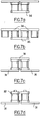
- Modules as shown in FIG. figure 1 comprising a housing 10 in which are disposed several electrical energy storage assemblies 20 connected by connection means 30.
- connection means 30 for the electrical connection of two adjacent storage assemblies 20 comprise two covers 32 and a bar 31.
- Each cover 32 is for capping a respective storage assembly 20 so as to be electrically connected thereto.
- Each cover 32 further comprises a connection terminal 33 adapted to come into contact with a through bore of the bar 31, so as to electrically connect two adjacent storage assemblies 20.
- the storage assemblies 20 are connected two by two alternatively at their upper and lower lids 32.
- the storage assemblies 20 and the connection means 30 produce heat. To allow this heat to be evacuated, the storage assemblies 20 are thermally connected to the housing 10.
- the storage assemblies 20 are held against the upper and lower walls 12, 13, of the housing 10 (through the covers 32).
- a storage assembly 20 rises in internal pressure due to production by the gas storage assembly that the sealed nature of the housing prevents releasing.
- the tearing of the internal connectivity induces an increase in resistance of the storage assembly 20.
- the end of life of the storage assembly 20 is easily detectable, following the evolution of the resistance thereof.
- the document DE 19958411 describes a module comprising a housing inside which is disposed an electrical energy storage assembly. However, the latter is absolutely not held against the bottom wall of the housing but is, on the contrary, removed. In addition, the current bushings 26, 32 or spacers 30 prevent any swelling of the outer shell of the energy storage assembly.
- the general object of the invention is to provide a module for overcoming the disadvantages of the modules described above.
- a module comprising a housing in which is disposed at least one electrical energy storage assembly comprising a first face in thermal contact while being electrically insulated with at least the bottom wall of the housing, and a second face opposite to the first face, the second face being capped by a cover electrically connected to said energy storage assembly, wherein the module comprises means for holding the associated storage assembly against the lower wall of the housing of a housing; on the other hand, and allowing the lid on the other side to swell.
- the module according to the invention allows a certain swelling of the covers associated with the storage assemblies and thus the detection, either of a possible increase in the internal resistance of a module storage assembly, synonymous with the end of life of the storage assembly concerned, ie the measurement of swelling by an associated sensor.
- a swelling of 1 mm, or 2 or 3 mm will be representative of the probability of remaining life of said assembly under normal operating conditions. Knowledge of this information will allow the preventive maintenance of the module to be managed according to the remaining probable life of each of its assemblies.
- the module comprises a housing 10 in which is disposed at least one electrical energy storage assembly 20.
- the storage assembly 20 comprises a first face in thermal contact while being electrically insulated with the bottom wall 13 of the housing 10.
- the storage assembly 20 also includes a second face opposite to the first face. This second face is capped by a cover 32 electrically connected to the energy storage assembly.
- the cover 32 is a connection means element 30 for connecting two adjacent storage assemblies 20.
- the module comprises means 16 for holding the storage assembly 20 against the bottom wall 13 of the housing On the one hand, and allowing inflation of the lid 32 covering the second face on the other hand.
- the module according to the invention allows the swelling of the lid 32 covering the second face of the storage assembly. This allows the detection of the end of life of the storage assembly concerned, either by means of individual sensors on each storage assembly, connected to information processing means, or directly by measuring a possible increase in the internal resistance. of the energy storage set.
- the sensors can measure, either the pressure, on the wall that carries it, related to the swelling of a set, or the deformation of the lid or a terminal strip, or still not measure the swelling but simply indicate the achievement a predetermined level of inflation by means of a simple switch.
- the information collected is transmitted to be exploited, either to a module energy management and diagnostic card, or to a module connector to an external electronic means of energy management and diagnostics of the module. energy storage sets.
- the means for maintaining the assembly 20 on the one hand and the swelling of the lid 32 on the other hand comprise a recess 16 on the inner face of the upper wall 12 of the housing 10 facing the lid 32.
- the recess 16 extends to the right of the storage assembly 20.
- This recess 16 may be for example a groove or a blind hole.
- the recess is made in the form of a blind hole, then the contour is equivalent to that of the shape of the storage assemblies: thus, if the sets are of cylindrical shape, the blind hole will be too. Likewise, if the shape of the storage assemblies is generally square, the blind hole will be likewise. In all cases, the recess is provided so that its dimensions are smaller than the cover of the associated storage assembly, so that the latter, despite the swelling of which it is the object, always remains in thermal contact with the upper wall of the module through the edge of the recess, while remaining electrically isolated from the latter.
- the means making it possible to hold the associated storage assembly against the lower wall of the housing on the one hand, and allowing the lid on the second face to swell consist of a compressible material, said material being compressed to a nominal value sufficiently lower than its maximum compression ratio to allow the swelling of the energy storage assemblies of a thickness between that corresponding to said nominal value of the material and that corresponding to the maximum compression ratio of said material.
- the material when closing the module, the material is compressed and keeps the storage assemblies in contact with the lower wall of the module. But because the maximum compression ratio of the material is not reached, the lid of the element can inflate with a thickness corresponding to the available space until reaching the compressible material is maximum compression.
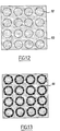
- the compressible material 60 may comprise various types of shaping: To the figure 12 this material covers all the storage assemblies uniformly.
- the material has zones 61 of different compressibility in front of each lid, so that it compresses the edge of the lid more than the center: this has the advantage of leaving a greater margin of compression in the center while mechanically blocking the edges, which creates a "virtual virtual" by the only properties of the material used.
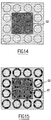
- the figure 14 shows the case where one has chosen to use a material whose compression in the central zone of the module is greater than that of the edges of the module, so as to have a compression ratio on the lids stronger in the central zone 62 more thermally constrained than on the edges where the energy storage assemblies are better cooled.
- This particular arrangement makes it possible to better take into account a shorter service life of the storage assemblies located in the center of the module compared with those of the storage assemblies located on the periphery of the module, and to balance the individual information of the storage assemblies. , taking into account their layout in the module.
- a stronger compression in the center will eventually delay the swelling of storage assemblies more strongly heat constrained and thus reduce the internal resistance imbalance in the module.
- the figure 15 combines the benefits described with figures 13 and 14 by cumulating a greater compressibility in the central zone of the module and a differential compressibility further accentuated at the edges of each of the storage assembly covers located in said central zone.
- FIG. figure 16 How to obtain a different compressibility in an annular area on the edges of the covers can be achieved as shown in FIG. figure 16 : At the top of the figure shows the compressible material before closure of the module, it is found that the material comprises a thickened annular zone 63, so that, once compressed, this zone 64 (shown on the lower part of the drawing) has compared to the rest of the material a higher compression ratio.
- an electrically conductive material capable of undergoing deformation and forming a barrier to the gases generated in the storage assemblies during their operation.
- the thickness of the lid is also chosen so as to allow the latter to swell as a function of the nature of the material constituting said lid.
- the material chosen will be aluminum and more specifically an aluminum with an aluminum content greater than 99.5%.
- the mechanical properties of an aluminum alloy are directly related to its purity: the less impurities it contains, the easier it is to deform.
- a recess 16 is associated with each storage assembly 20.
- connection means 30 When the device comprises several storage assemblies 20, these are electrically connected in pairs by means of connection means 30.
- connection means 30 allowing the electrical connection between two adjacent storage assemblies 20 comprise two covers 32, associated respectively with the two storage assemblies 20, and a bar 31.
- the dimensions of the recess are provided so that at least a portion of the edge of the recess 16 is in thermal contact while being electrically insulated with the connection means 30.
- the figure 2 illustrates two different examples of thermal contact between the connection means 30 and the recess 16.
- the edges of the recess 16 are in thermal contact while being electrically insulated with the cover 32.
- the edges of the recess 16 are in thermal contact while being electrically insulated with the bar 31.
- the recess comprises, in certain variants, a layer of elastomer material at least on its edge in thermal contact while being electrically insulated with the connection means 30.
- the module comprises a housing 10 in which electrical energy storage assemblies 20 are arranged connected by connection means 30.
- the module also comprises an electronic management card 40 for energy management and diagnosis of energy storage assemblies 20, the card being visible at the figure 11 .
- the storage assemblies 20 are of generally cylindrical shape.
- the storage assemblies 20 are arranged side by side in the housing 10. In other words, the axes of revolution of the storage assemblies 20 are parallel. In other variants not shown here, the storage assemblies may be parallelepipedal, square, oval, hexagonal, without this changing the general principles of the invention.
- the storage assemblies 20 are arranged so that their axes of revolution are perpendicular to the upper walls 12 and lower 13 of the housing 10.
- the thermal connection of the storage assemblies 20 with a first wall 12, 13 and the electronic management card 40 with a second wall 14 different from the first wall 12, 13 makes it possible to maximize the heat dissipation of the heat emitted by the card 40 and the storage assemblies 20 to the outside of the module.
- the heat dissipation elements may comprise the connection means 30.
- the dissipation elements 38 may also comprise an elastomer layer disposed between the means of connection 30 and the housing wall in thermal contact with the storage assemblies 20.
- the wall in contact with the heat dissipating elements is the bottom wall 13 of the housing 10, and the wall in contact with the electronic management card 40 is a side wall 14 of the housing 10.
- the storage assemblies 20 preferentially conduct heat along their axis of revolution (longitudinal axis), so that axial cooling of the storage assemblies 20 is more effective than radial cooling thereof.
- the storage assemblies 20 are thermally connected to either the upper wall 12, the lower wall 13 or the upper and lower walls 12, 13 of the housing 10.
- the storage assemblies 20 are thermally connected to the upper and lower walls 12, 13.
- the fins 15, 15 ' improve the cooling of the assembly.
- the thermal contacting of the storage assemblies with two walls makes it possible to improve the cooling of the storage assemblies by increasing the heat exchange surface between the storage assemblies 20 and the outside of the module.
- the housing 10 allows handling of the module, reinforces the electrical insulation and protects the core of the module and its electronics from potential external aggressions.
- This housing can be parallelepiped, to be arranged in the place currently used by a motor vehicle battery, or cylindrical, for example to be housed in the space released by a spare wheel, or prismatic, defining in any case upper and lower faces, and side faces.
- the upper, lower, and lateral walls of the casing are made of anodized aluminum in order to promote the cooling of the module on the one hand, via a better radiative dissipation, and to reinforce the resistance to corrosion of the module. on the other hand.
- walls 12, 13, 14 of aluminum or of carbon composite material makes it possible to improve the thermal conduction between the inside and the outside of the housing with respect to walls made of plastic material or steel with mechanical characteristics. identical. This increases the cooling efficiency of the storage assemblies 20 and the electronic card 40.
- the housing 10 comprises fins 15 as shown in FIGS. Figures 4 and 5 .
- the fins 15 may be arranged on at least one outer face of a wall 12, 13, 14 of the housing 10.
- the stiffeners 15 'disposed on the side walls also constitute fins within the meaning of this patent since they allow to increase the convective exchange surface of the walls.
- the fins 15 are disposed on the outer face of the wall of the housing in thermal contact. with the storage assemblies 20 so as to improve the cooling of said storage assemblies 20.
- the fins 15 are arranged in a central region of the outer face of the upper wall 12 of the housing 10.
- the fins 15 are disposed on the outer face of the wall of the housing 10 in thermal contact with the electronic management card 40 so as to improve the cooling of said electronic management card 40.
- the outer faces of the walls 12, 13, 14 in thermal contact with the storage assemblies 20 on the one hand and the electronic card (s) 40 on the other hand. part include fins 15.
- the wall in thermal contact with the storage assemblies 20 comprises, or is associated with, a base (not shown ) in which a cooling device (not shown) is arranged.
- the cooling device may comprise a circulation circuit of a cooling fluid.
- the module can comprise a device for cooling in one or all walls in thermal contact with the assemblies 20.
- the module comprises twenty sets of electrical energy storage 20.
- the storage assemblies are of generally cylindrical shape.
- the storage assemblies 20 are arranged in the housing 10, parallel to each other and parallel to the side walls of the housing. In other words, the axes of revolution of the storage assemblies 20 are parallel to one another and parallel to each plane in which a respective lateral wall extends.
- the storage assemblies 20 are arranged so that their axes of revolution are perpendicular to the upper walls 12 and lower 13 of the housing 10.
- the storage assemblies 20 are connected in pairs by the connection means 30 which will be described in detail in the following description.
- These storage assemblies 20 are connected two by two alternately at their upper lids 32 and lower 32.
- the latter is connected by its upper cover to a first set adjacent storage, and by its lower cover to a second adjacent storage assembly different from the first storage assembly.
- the storage assemblies are electrically isolated from the walls 12, 13, 14 of the housing 10.
- the device also comprises four electronic management cards 40.
- the electronic management card 40 makes it possible to manage the charging and discharging and the diagnosis of the energy storage assemblies 20.
- diagnosis here is meant all the measurements of temperature, pressure, voltage and current allowing measurement and / or or calculate the state of charge or state of health of the module during its working life.
- the storage assemblies 20 have characteristics (capacity, resistances) having dispersions due to manufacture, and / or aging, etc.
- Balancing therefore comprises the homogenization of these voltages around the same voltage value defined according to the intended application.
- the management board is connected in parallel with the associated storage sets in series.
- the electronic management board 40 is electrically isolated from the walls of the housing 10.
- An electronic management card 40 comprises an epoxy resin layer 42 on which is glued a copper printed circuit board 41.
- the epoxy resin layer 42 allows the thermal contact while ensuring the electrical isolation of the copper printed circuit 41 with the housing 10.
- the electronic management board 40 is arranged so that the epoxy resin layer 42 comes into contact with the inner face of the wall 14 of the housing 10.
- the electronic management board 40 comprises an aluminum plate 43 on the epoxy resin layer 42 (so that the epoxy resin layer is located between the copper circuit board and the aluminum layer).
- the electronic cards 40 may be arranged outside the housing, and thus thermally connected to the outer faces of the side walls of the latter.
- Such an arrangement may have the advantage of further improving the cooling of the cards, and to ensure easier maintenance, without having to open the case, but present for disadvantages to expose them more easily to external shocks, and to require an improvement in the sealing of the walls of the housing.
- the presence, on the electronic management board 40, of an aluminum layer 43 favors the evacuation of the heat from the copper circuit board 41 towards the wall 14 of the housing 10 in contact with the electronic management card 40.
- the module can comprise as many electronic management cards 40 as the housing 10 comprises lateral walls 14.
- the module comprises four electronic management cards 40 thermally connected to the inner faces of the four side walls 14 of the housing 10.
- the presence of four electronic boards on the four side walls of the module prevents the storage assemblies located at the periphery of the housing from cooling faster than the storage assemblies 20 located in the center of the housing.
- thermal buffer the role of thermal buffer.
- the presence of these thermal buffers on the side walls induces that the storage assemblies 20 disposed near the side walls 14 will cool less rapidly so that all the storage assemblies 20 of the module will cool at the same speed.
- the number of electronic cards will be optimized according to the thermal result to be obtained, without the number of cards must necessarily be identical to the number of side walls of the housing, especially when the housing has a circular or complex shape related to the particular environment in which the module is operated.
- the connecting means 30 between two adjacent storage assemblies 20 comprise two covers 32 electrically connected by a bar 31.
- Each cover 32 is intended to cap a storage assembly 20.
- Each cover 32 comprises a connection terminal 33 intended to be in contact with a through bore (not shown) of the bar 31.
- a connection terminal 33 intended to be in contact with a through bore (not shown) of the bar 31.
- the surface state of the bore through can be roughened to increase the contact area.
- the bars 31 are made of copper. This makes it possible to reduce the ohmic resistance of the connection means 30 and thus to minimize Joule losses. Thus, the production of heat by the connection means 30 is reduced within the module.
- the bars 31 are made of aluminum. This makes it possible to improve the mass of the connection means while maintaining an ohmic resistance between the storage assemblies and a satisfactory thermal conduction between the storage assemblies 20 and the housing 10.
- the strips 31 may be coated with a nickel-plated or tin-plated surface treatment to protect them against corrosion, but also to improve the electrical contact.
- each storage assembly 20 the top cover 32 of the assembly 20 is electrically connected with the top cover 32 of an adjacent assembly, while the lower cover 32 'of the same assembly is electrically connected with the bottom cover 32' of a further adjacent storage assembly so that each storage assembly 20 can be connected to two adjacent storage assemblies 20, one at its top cover and the other at its lower cover.
- the energy storage assemblies have flat lids without connection terminals. They are then welded or brazed in pairs with their neighbors by means of welded or brazed bars in the same arrangement as described in the previous paragraph. In the case of laser welding transparency, the bars may have preferred areas thinned, similar to those described below about the welding of bi-lids.
- the contact surface between the bar 31 and a cover 32 is preferably greater than or equal to a quarter of the surface of the cover 32, and even more preferably greater than or equal to half the surface of the cover 32, or even over the entire area of the cover 32. the surface of the lid.
- This configuration of the storage assemblies makes it possible to maximize the contact area between the bar 31 and the cover and thus to promote heat exchange between the cover and the housing through the bar 31.
- connection means 30 comprise a longitudinal part 34, called a bi-cover, the ends 35, 36 of which form the upper covers or the lower covers of two adjacent storage assemblies 20 for electrically connecting them.
- the use of the longitudinal part 34 to electrically connect two adjacent storage assemblies increases the electrical and thermal performance of the modules.
- connection means made in one piece reduces the internal resistance of the connection means (and therefore the heat production Joule effect).
- connection means capable of forming the upper (or lower) covers of two storage assemblies enables to increase the contact area between the storage assemblies 20 and the walls of the module, which promotes thermal diffusion towards the housing 10.
- each end 35, 36 of the bi-lid 34 comprises thinned preferential zones 37 to form welding zones.
- the thinned preferential zones 37 are radial and perpendicular two by two.
- a preferred thinned area 37 of each end 35, 36 extends along the longitudinal axis BB of the longitudinal piece 34.
- the current flows mainly at the level of the linear thinned areas extending along the longitudinal axis BB of the longitudinal piece 34. This can cause local heating of the longitudinal piece at the level of the rectilinear thinned zones extending along the longitudinal axis BB of the longitudinal piece 34.
- the radial straight thinned areas 37 are perpendicular in pairs and have an angle of 45 ° with the longitudinal axis of the workpiece. This avoids the risk of deterioration related to local warming mentioned above.
- the number of storage sets of the module may be greater than or less than 20.
- the module may include 2, power storage assemblies, or more than 2 storage sets.
- the edges of the recess 16 are in thermal contact while being electrically insulated with the storage assembly 20.
- the cover is crimped inside from the whole.
- the cover 32 is secured on the internal face of the side wall of the storage assembly 20, near its upper end (so that the cover 32 extends generally below the upper edge of the storage assembly 20).
- the recess is in thermal contact while being electrically insulated with both the cover 32 and the storage assembly 20.
- the housing may comprise, for each set of storage more than one recess.
- the housing may comprise two recesses, one made in the inner face of the upper wall and the other made in the inner face of the lower wall.
- the invention also covers the case where the recesses are located opposite the lower wall, and thus where the swelling of the storage assemblies would be in the lower part of the module.
- the number of electronic management cards may be greater than or less than 4.
- the module may comprise a single management card.
- the two storage assemblies are thermally connected to a first wall and the management electronic card is connected to a second wall - different from the first wall - so as to increase heat exchange with the outside, and thus favor the evacuation of the heat produced by the storage assemblies, the connection means and the electronic management card.
- the geometric arrangement of the storage assemblies is described above in square array, but can also be of any shape, such as triangular, parallelogram, hexagonal, octagonal, etc.
- modules extending globally vertically.
- the modules could have any orientation without departing from the scope of the invention.
- storage assemblies and their orientation has been defined with respect to storage assemblies comprising a circular section.
- the storage sets could have any section.
Landscapes
- Engineering & Computer Science (AREA)
- General Chemical & Material Sciences (AREA)
- Chemical & Material Sciences (AREA)
- Chemical Kinetics & Catalysis (AREA)
- Electrochemistry (AREA)
- Manufacturing & Machinery (AREA)
- Microelectronics & Electronic Packaging (AREA)
- Power Engineering (AREA)
- Battery Mounting, Suspending (AREA)
- Secondary Cells (AREA)
- Connection Of Batteries Or Terminals (AREA)
- Sealing Battery Cases Or Jackets (AREA)
- Electric Double-Layer Capacitors Or The Like (AREA)
Priority Applications (1)
| Application Number | Priority Date | Filing Date | Title |
|---|---|---|---|
| PL08717076T PL2174366T3 (pl) | 2007-05-15 | 2008-02-25 | Moduł do zespołów magazynujących energię elektryczną umożliwiający wykrywanie starzenia się tych zespołów |
Applications Claiming Priority (2)
| Application Number | Priority Date | Filing Date | Title |
|---|---|---|---|
| FR0755089A FR2916306B1 (fr) | 2007-05-15 | 2007-05-15 | Module pour ensembles de stockage d'energie electrique permettant la detection du vieillissement desdits ensembles. |
| PCT/EP2008/052231 WO2008141845A1 (fr) | 2007-05-15 | 2008-02-25 | Module pour ensembles de stockage d'energie electrique permettant la detection du vieillissement desdits ensembles |
Publications (2)
| Publication Number | Publication Date |
|---|---|
| EP2174366A1 EP2174366A1 (fr) | 2010-04-14 |
| EP2174366B1 true EP2174366B1 (fr) | 2019-08-07 |
Family
ID=38687372
Family Applications (1)
| Application Number | Title | Priority Date | Filing Date |
|---|---|---|---|
| EP08717076.7A Active EP2174366B1 (fr) | 2007-05-15 | 2008-02-25 | Module pour ensembles de stockage d'energie electrique permettant la detection du vieillissement desdits ensembles |
Country Status (14)
| Country | Link |
|---|---|
| US (1) | US8906531B2 (he) |
| EP (1) | EP2174366B1 (he) |
| JP (2) | JP2010527127A (he) |
| KR (1) | KR101537119B1 (he) |
| CN (1) | CN101682009B (he) |
| CA (1) | CA2685199C (he) |
| DK (1) | DK2174366T3 (he) |
| ES (1) | ES2749873T3 (he) |
| FR (1) | FR2916306B1 (he) |
| IL (1) | IL201893A (he) |
| PL (1) | PL2174366T3 (he) |
| RU (1) | RU2449450C2 (he) |
| UA (1) | UA95364C2 (he) |
| WO (1) | WO2008141845A1 (he) |
Families Citing this family (30)
| Publication number | Priority date | Publication date | Assignee | Title |
|---|---|---|---|---|
| CN102396141B (zh) * | 2009-04-14 | 2014-07-09 | 三菱电机株式会社 | 电源装置 |
| AT509573B1 (de) * | 2010-02-25 | 2012-01-15 | Norman Neuhold | Akkumulatoreinheit |
| JP2012074561A (ja) * | 2010-09-29 | 2012-04-12 | Omron Corp | 電解コンデンサ用ソケット |
| JP5327175B2 (ja) * | 2010-09-30 | 2013-10-30 | オムロン株式会社 | 電解コンデンサ用表面実装ソケット及び電解コンデンサの表面実装方法 |
| DE102011080950A1 (de) * | 2011-08-15 | 2013-02-21 | Behr Gmbh & Co. Kg | Vorrichtung zur Wärmeabfuhr aus einem Energiespeicher |
| FR2979472B1 (fr) * | 2011-08-29 | 2013-08-23 | Batscap Sa | Connecteur dispose entre deux ensembles de stockage d'energie |
| FR2979473B1 (fr) | 2011-08-29 | 2013-08-16 | Batscap Sa | Ensemble de stockage d'energie longue duree a piece de connexion intermediaire |
| FR2986657B1 (fr) * | 2012-02-03 | 2014-01-31 | Batscap Sa | Entretoise de positionnement, module de stockage d'energie l'ayant et procede d'assemblage du module |
| FR3007887A1 (fr) * | 2013-06-27 | 2015-01-02 | Batscap Sa | Procede de fabrication d'un module de stockage d'energie electrique, dispositif de fabrication associe et module de stockage d'energie electrique obtenu en mettant en oeuvre le procede |
| FR3013900B1 (fr) * | 2013-11-22 | 2015-12-11 | Blue Solutions | Module de stockage d'energie, comprenant une pluralite d'ensembles de stockage d'energie |
| US10833376B2 (en) | 2014-01-02 | 2020-11-10 | Cps Technology Holdings Llc | Battery with life estimation |
| JP6176632B2 (ja) * | 2014-06-30 | 2017-08-09 | 東洋ゴム工業株式会社 | 組電池の異常判定方法及び組電池の異常判定装置 |
| US10608290B2 (en) * | 2014-11-27 | 2020-03-31 | Semiconductor Energy Laboratory Co., Ltd. | Flexible battery and electronic device |
| FR3042093B1 (fr) | 2015-10-05 | 2017-10-06 | Blue Solutions | Module de stockage d'energie electrique et son procede de fabrication |
| KR102484264B1 (ko) * | 2015-11-24 | 2023-01-02 | 삼성에스디아이 주식회사 | 이차 전지 및 그의 제조 방법 |
| US9954205B2 (en) | 2016-04-12 | 2018-04-24 | Energizer Brands, Llc | Slotted battery cavity for multiple cell sizes |
| DE102016206671A1 (de) * | 2016-04-20 | 2017-10-26 | Robert Bosch Gmbh | Längenausdehnungsüberwachung zur Bestimmung der Alterung einer Batteriezelle oder eines Batteriemoduls |
| KR102263409B1 (ko) * | 2016-10-31 | 2021-06-11 | 주식회사 엘지에너지솔루션 | 스웰링을 방지하는 구조로 이루어진 전지셀 |
| EP3631876B1 (en) * | 2017-05-23 | 2025-04-16 | Aceleron Limited | Battery pack assembly |
| WO2019005537A1 (en) * | 2017-06-30 | 2019-01-03 | Avx Corporation | DISSIPATING HEAT FROM A BALANCING CIRCUIT FOR A ULTRAC-COMPENSATOR MODULE |
| US12119462B2 (en) * | 2018-01-04 | 2024-10-15 | Lyten, Inc. | Sensing device for detecting analytes in batteries |
| FR3086103A1 (fr) * | 2018-09-19 | 2020-03-20 | Psa Automobiles Sa | Systeme de climatisation pour une batterie, vehicule comprenant un systeme de climatisation pour une batterie |
| EP3973590A1 (en) | 2019-05-21 | 2022-03-30 | General Electric Company | Temperature control mechanism for an electrical component |
| EP4024562B1 (en) * | 2019-11-20 | 2025-04-16 | Lg Energy Solution, Ltd. | Apparatus and method for detecting swelling of battery module |
| JP7237899B2 (ja) * | 2020-09-03 | 2023-03-13 | 三恵技研工業株式会社 | バッテリー熱交換構造 |
| RU2746262C1 (ru) * | 2020-10-21 | 2021-04-12 | Общество с ограниченной ответственностью "Технопрогресс" (ООО "Технопрогресс") | Аккумуляторная сборка и способ ее изготовления |
| EP4231422A4 (en) * | 2021-04-23 | 2024-09-18 | LG Energy Solution, Ltd. | BATTERY MODULE AND BATTERY PACK COMPRISING SAME |
| KR102815177B1 (ko) * | 2021-10-26 | 2025-05-30 | 주식회사 엘지에너지솔루션 | 셀 트레이 |
| JP2024000995A (ja) * | 2022-06-21 | 2024-01-09 | ミルウォーキー エレクトリック ツール コーポレイション | バッテリパック |
| KR102870855B1 (ko) * | 2024-07-03 | 2025-10-15 | 제이인스 주식회사 | 고전압 및 대용량 전기 이중층 커패시터 |
Citations (1)
| Publication number | Priority date | Publication date | Assignee | Title |
|---|---|---|---|---|
| EP1780825A1 (en) * | 2005-10-31 | 2007-05-02 | Black & Decker, Inc. | Battery pack and internal component arrangement within the battery pack for cordless power tool system |
Family Cites Families (57)
| Publication number | Priority date | Publication date | Assignee | Title |
|---|---|---|---|---|
| FR1081226A (fr) | 1953-04-27 | 1954-12-16 | Rech S Et D Applic Physicochim | Dispositif pour le montage d'une chaîne sensiblement verticale de condensateurs électriques |
| US3255387A (en) * | 1960-04-27 | 1966-06-07 | Sprague Electric Co | Sealed capacitor and method of assembling same |
| GB1230591A (he) * | 1967-10-14 | 1971-05-05 | ||
| US4224385A (en) * | 1979-01-02 | 1980-09-23 | P. R. Mallory & Co. Inc. | Expandable battery case |
| FR2475285A1 (fr) | 1980-02-05 | 1981-08-07 | Europ Composants Electron | Condensateur multi-elements a haute dissipation thermique |
| US4431717A (en) * | 1981-01-31 | 1984-02-14 | Sony Corporation | Battery case |
| US4724189A (en) * | 1985-05-31 | 1988-02-09 | Frank Chase | Conversion module system |
| SU1728928A1 (ru) * | 1989-01-30 | 1992-04-23 | Г.М.Легошин | Устройство дл накоплени электрической энергии |
| US5223690A (en) | 1990-11-29 | 1993-06-29 | Alexander Manufacturing Company | Process and apparatus for spot-welding a flexible welding board to a battery cell |
| US5227263A (en) * | 1992-05-22 | 1993-07-13 | The United States Of America As Represented By The Secretary Of The Navy | Reconfigurable heavy duty battery holder |
| US5711988A (en) * | 1992-09-18 | 1998-01-27 | Pinnacle Research Institute, Inc. | Energy storage device and its methods of manufacture |
| FR2712733B1 (fr) | 1993-11-16 | 1996-02-09 | Bollore Technologies | Procédé de fabrication d'un ensemble électrochimique multicouche comprenant un électrolyte entre deux électrodes et ensemble ainsi réalisé. |
| JPH10255750A (ja) * | 1997-03-13 | 1998-09-25 | Japan Storage Battery Co Ltd | 電池装置 |
| JP3166661B2 (ja) * | 1997-06-05 | 2001-05-14 | エフ・ディ−・ケイ株式会社 | 電池パック |
| US6303248B1 (en) * | 1997-06-10 | 2001-10-16 | Roland K. Peterson | Solderless battery pack |
| US6146778A (en) * | 1997-07-25 | 2000-11-14 | 3M Innovative Properties Company | Solid-state energy storage module employing integrated interconnect board |
| DE10002142B4 (de) * | 1999-01-28 | 2004-04-29 | Sanyo Electric Co., Ltd., Moriguchi | Stromversorgung enthaltend wiederaufladbare Batterien |
| SE9903153D0 (sv) | 1999-09-03 | 1999-09-03 | Electronique Ind Departement D | A method and an apparatus for equalising the votltages over the capacitors in a series connection of capacitors during charging and discharging |
| DE19958411A1 (de) * | 1999-12-03 | 2001-06-07 | Diehl Munitionssysteme Gmbh | Thermalbatterie |
| JP4079572B2 (ja) | 2000-04-14 | 2008-04-23 | 松下電器産業株式会社 | 電池パック |
| JP2002124236A (ja) * | 2000-10-12 | 2002-04-26 | Toyota Motor Corp | 密閉型電池 |
| JP3838872B2 (ja) | 2000-12-13 | 2006-10-25 | 松下電器産業株式会社 | 電池間接続構造および接続方法 |
| JP2002353078A (ja) | 2001-05-29 | 2002-12-06 | Asahi Glass Co Ltd | 積層型電気二重層キャパシタモジュール |
| EP1406340B1 (en) * | 2001-06-05 | 2008-07-23 | GS Yuasa Corporation | Storage battery device and power source apparatus comprising it |
| JP2003007256A (ja) * | 2001-06-20 | 2003-01-10 | Japan Storage Battery Co Ltd | 非水電解質電池 |
| JP2003045760A (ja) * | 2001-07-30 | 2003-02-14 | Asahi Glass Co Ltd | 積層型電気二重層キャパシタモジュール |
| JP4593031B2 (ja) * | 2001-08-06 | 2010-12-08 | パナソニック株式会社 | 角形密閉式電池 |
| JP3960766B2 (ja) * | 2001-09-07 | 2007-08-15 | 三洋電機株式会社 | 二次電池 |
| JP5049436B2 (ja) * | 2001-09-28 | 2012-10-17 | パナソニック株式会社 | 組電池 |
| US6714391B2 (en) * | 2001-10-04 | 2004-03-30 | Ise Research Corporation | Ultracapacitor energy storage cell pack and methods of assembling and cooling the same |
| JP2003142146A (ja) * | 2001-10-31 | 2003-05-16 | Japan Storage Battery Co Ltd | 電 池 |
| DE10218295A1 (de) | 2002-04-24 | 2003-11-13 | Epcos Ag | Kondensatormodul und Kondensatorbatterie mit dem Kondensatormodul |
| JP2006500790A (ja) | 2002-09-27 | 2006-01-05 | エーペーツェーオーエス アーゲー | 電気部品要素及び当該部品要素を備える装置 |
| JP4002192B2 (ja) * | 2003-01-23 | 2007-10-31 | 矢崎総業株式会社 | 密閉型二次電池 |
| JP4036805B2 (ja) * | 2003-08-05 | 2008-01-23 | 三洋電機株式会社 | パック電池 |
| DE10337041A1 (de) | 2003-08-12 | 2005-03-10 | Epcos Ag | Kondensatormodul und Verfahren zu dessen Herstellung |
| JP4721628B2 (ja) * | 2003-08-29 | 2011-07-13 | トヨタ自動車株式会社 | 電池ケース及びその製造方法 |
| EP1571748A4 (en) | 2003-09-18 | 2014-04-30 | Panasonic Corp | CAPACITOR UNIT |
| US6952338B1 (en) * | 2003-11-07 | 2005-10-04 | Sony Corporation | Common pole capacitor housing apparatus and method |
| US7180726B2 (en) * | 2003-11-07 | 2007-02-20 | Maxwell Technologies, Inc. | Self-supporting capacitor structure |
| US7016177B1 (en) * | 2003-11-07 | 2006-03-21 | Maxwell Technologies, Inc. | Capacitor heat protection |
| US7203056B2 (en) * | 2003-11-07 | 2007-04-10 | Maxwell Technologies, Inc. | Thermal interconnection for capacitor systems |
| FR2863400B1 (fr) | 2003-12-03 | 2006-03-24 | Electricite De France | Systeme a supercondensateurs et procede d'assemblage d'un tel systeme |
| US6942359B2 (en) * | 2003-12-08 | 2005-09-13 | Eveready Battery Company, Inc. | Flashlight that can operate with alternative size batteries |
| DE102004010712A1 (de) | 2004-03-04 | 2005-09-22 | Epcos Ag | Gehäuse für Hochleistungsbauteile |
| DE102004035810A1 (de) | 2004-07-23 | 2006-02-16 | Epcos Ag | Kondensatormodul |
| DE102004039231A1 (de) | 2004-08-12 | 2006-02-23 | Epcos Ag | Kondensatormodul |
| DE102004045182B4 (de) | 2004-09-17 | 2008-10-16 | Epcos Ag | Kondensatormodul |
| JP4513494B2 (ja) * | 2004-10-15 | 2010-07-28 | トヨタ自動車株式会社 | 電圧変換装置の制御装置及び制御方法 |
| DE102004054082B4 (de) | 2004-11-09 | 2008-02-28 | Epcos Ag | Gehäuse für einen Kondensator, elektrischer Kondensator und Kondensatormodul |
| DE102005007607A1 (de) | 2005-02-18 | 2006-08-24 | Epcos Ag | Kondensatormodul |
| KR100684795B1 (ko) * | 2005-03-29 | 2007-02-20 | 삼성에스디아이 주식회사 | 이차 전지 및 이차 전지 모듈 |
| US20070009787A1 (en) * | 2005-05-12 | 2007-01-11 | Straubel Jeffrey B | Method and apparatus for mounting, cooling, connecting and protecting batteries |
| US7586736B2 (en) * | 2005-07-11 | 2009-09-08 | Micro Power Electronics Inc. | Electrical insulation system and method for electrical power storage component separation |
| FR2888669B1 (fr) * | 2005-07-13 | 2010-08-20 | Batscap Sa | Systeme d'interconnexion pour un ensemble de stockage d'energie |
| JP2007027011A (ja) * | 2005-07-20 | 2007-02-01 | Sanyo Electric Co Ltd | 電源装置 |
| US7687197B2 (en) * | 2005-10-07 | 2010-03-30 | Research In Motion Limited | Expandable battery compartment for handheld electronic devices |
-
2007
- 2007-05-15 FR FR0755089A patent/FR2916306B1/fr not_active Expired - Fee Related
-
2008
- 2008-02-25 JP JP2010507860A patent/JP2010527127A/ja active Pending
- 2008-02-25 RU RU2009146387/07A patent/RU2449450C2/ru not_active IP Right Cessation
- 2008-02-25 PL PL08717076T patent/PL2174366T3/pl unknown
- 2008-02-25 DK DK08717076.7T patent/DK2174366T3/da active
- 2008-02-25 US US12/599,961 patent/US8906531B2/en not_active Expired - Fee Related
- 2008-02-25 KR KR1020097026058A patent/KR101537119B1/ko not_active Expired - Fee Related
- 2008-02-25 ES ES08717076T patent/ES2749873T3/es active Active
- 2008-02-25 UA UAA200912895A patent/UA95364C2/ru unknown
- 2008-02-25 WO PCT/EP2008/052231 patent/WO2008141845A1/fr not_active Ceased
- 2008-02-25 CN CN2008800160395A patent/CN101682009B/zh not_active Expired - Fee Related
- 2008-02-25 CA CA2685199A patent/CA2685199C/fr not_active Expired - Fee Related
- 2008-02-25 EP EP08717076.7A patent/EP2174366B1/fr active Active
-
2009
- 2009-11-03 IL IL201893A patent/IL201893A/he active IP Right Grant
-
2013
- 2013-04-30 JP JP2013095013A patent/JP5686842B2/ja not_active Expired - Fee Related
Patent Citations (1)
| Publication number | Priority date | Publication date | Assignee | Title |
|---|---|---|---|---|
| EP1780825A1 (en) * | 2005-10-31 | 2007-05-02 | Black & Decker, Inc. | Battery pack and internal component arrangement within the battery pack for cordless power tool system |
Also Published As
| Publication number | Publication date |
|---|---|
| JP2013179068A (ja) | 2013-09-09 |
| ES2749873T3 (es) | 2020-03-24 |
| US20100304201A1 (en) | 2010-12-02 |
| CA2685199A1 (fr) | 2008-11-27 |
| US8906531B2 (en) | 2014-12-09 |
| DK2174366T3 (da) | 2019-10-21 |
| JP5686842B2 (ja) | 2015-03-18 |
| KR101537119B1 (ko) | 2015-07-15 |
| IL201893A0 (en) | 2010-06-16 |
| KR20100017802A (ko) | 2010-02-16 |
| RU2009146387A (ru) | 2011-06-20 |
| EP2174366A1 (fr) | 2010-04-14 |
| PL2174366T3 (pl) | 2020-01-31 |
| WO2008141845A1 (fr) | 2008-11-27 |
| CN101682009B (zh) | 2012-12-19 |
| IL201893A (he) | 2015-01-29 |
| UA95364C2 (ru) | 2011-07-25 |
| AU2008253168A1 (en) | 2008-11-27 |
| RU2449450C2 (ru) | 2012-04-27 |
| CA2685199C (fr) | 2016-06-07 |
| CN101682009A (zh) | 2010-03-24 |
| JP2010527127A (ja) | 2010-08-05 |
| FR2916306B1 (fr) | 2009-07-17 |
| FR2916306A1 (fr) | 2008-11-21 |
Similar Documents
| Publication | Publication Date | Title |
|---|---|---|
| EP2174366B1 (fr) | Module pour ensembles de stockage d'energie electrique permettant la detection du vieillissement desdits ensembles | |
| EP2145360B1 (fr) | Module pour ensemble de stockage d'energie electrique. | |
| EP2599154B1 (fr) | Système de refroidissement de batterie électrique et batterie comprenant un tel système | |
| WO2012013641A1 (fr) | Batterie d'accumulateurs a conception et montage facilites | |
| FR3022402A1 (fr) | Batterie electrique modulaire comprenant un dispositif de protection et de regulation thermique | |
| FR3075475A1 (fr) | Systeme de suivi des gaz au sein d'un pack-batterie, accumulateur electrochimique metal-ion associe comprenant une traversee formant borne pour integrant un event de securite pour le systeme de suivi | |
| WO2012168648A1 (fr) | Dispositif de refroidissement de cellules electrochimiques cylindriques | |
| EP3732740A1 (fr) | Couvercle d'element electrochimique a conduction thermique renforcee | |
| FR3075476A1 (fr) | Piece d'interface mecanique et d'isolation electrique entre deux accumulateurs electrochimiques metal-ion alignes selon leur axe longitudinal, module d'accumulateurs associe | |
| EP3028287A1 (fr) | Module de stockage d'énergie comprenant une pluralité d'ensembles de stockage d'énergie | |
| FR3075478A1 (fr) | Sous-ensemble integrant un mandrin creux et une partie d'une traversee creuse formant borne pour accumulateur electrochimique metal-ion, accumulateur associe | |
| EP2810286B1 (fr) | Entretoise de positionnement, module de stockage d'energie l'utilisant et procede d'assemblage du module | |
| FR3073671A1 (fr) | Bloc energetique constitue par un assemblage sans soudure d'une pluralite de cellules de batteries | |
| FR2988915A3 (fr) | Structure de module de batterie pour cellules li-ion a enveloppe souple et module de batterie correspondant | |
| CA2847105C (fr) | Ensemble de stockage d'energie longue duree a piece de connexion intermediaire | |
| EP3809488A1 (fr) | Batterie d'accumulateurs factice | |
| FR3062522A1 (fr) | Batterie refroidie et systeme comportant une telle batterie | |
| EP3948905A1 (fr) | Bloc capacitif comprenant une entretoise | |
| FR3146027A1 (fr) | Cellule electrochimique disposant d’electrodes helicoïdales, vehicule automobile, dispositif electrique et procede sur la base d’une telle cellule | |
| EP3769364B1 (fr) | Dispositif de stockage electrique d'un vehicule, controlé thermiquement a l'aide de caloducs | |
| FR2967821A1 (fr) | Batterie d'accumulateurs electriques, notamment batterie de traction, et vehicule hybride ou electrique equipe d'une telle batterie | |
| EP2828920A1 (fr) | DISPOSITIF DE RÉGULATION THERMIQUE D'UN MODULE-BATTERIe | |
| FR3132393A1 (fr) | Procédé de fabrication d’un ensemble batterie | |
| FR3095302A1 (fr) | Dispositif de stockage à cellule électrochimique prismatique et à enveloppe de protection à protubérances, et batterie associée |
Legal Events
| Date | Code | Title | Description |
|---|---|---|---|
| PUAI | Public reference made under article 153(3) epc to a published international application that has entered the european phase |
Free format text: ORIGINAL CODE: 0009012 |
|
| 17P | Request for examination filed |
Effective date: 20091214 |
|
| AK | Designated contracting states |
Kind code of ref document: A1 Designated state(s): AT BE BG CH CY CZ DE DK EE ES FI FR GB GR HR HU IE IS IT LI LT LU LV MC MT NL NO PL PT RO SE SI SK TR |
|
| AX | Request for extension of the european patent |
Extension state: AL BA MK RS |
|
| RIN1 | Information on inventor provided before grant (corrected) |
Inventor name: DEPOND, JEAN-MICHEL Inventor name: LE BRAS, KARINE Inventor name: JUVENTIN-MATHES, ANNE-CLAIRE Inventor name: CAUMONT, OLIVIER |
|
| DAX | Request for extension of the european patent (deleted) | ||
| REG | Reference to a national code |
Ref country code: HK Ref legal event code: DE Ref document number: 1139510 Country of ref document: HK |
|
| RAP1 | Party data changed (applicant data changed or rights of an application transferred) |
Owner name: BLUE SOLUTIONS |
|
| 17Q | First examination report despatched |
Effective date: 20140612 |
|
| STAA | Information on the status of an ep patent application or granted ep patent |
Free format text: STATUS: EXAMINATION IS IN PROGRESS |
|
| RIC1 | Information provided on ipc code assigned before grant |
Ipc: H01M 2/20 20060101ALI20190116BHEP Ipc: H01G 11/82 20130101ALI20190116BHEP Ipc: H01M 10/42 20060101ALI20190116BHEP Ipc: H01M 2/10 20060101AFI20190116BHEP |
|
| GRAP | Despatch of communication of intention to grant a patent |
Free format text: ORIGINAL CODE: EPIDOSNIGR1 |
|
| STAA | Information on the status of an ep patent application or granted ep patent |
Free format text: STATUS: GRANT OF PATENT IS INTENDED |
|
| INTG | Intention to grant announced |
Effective date: 20190226 |
|
| RIN1 | Information on inventor provided before grant (corrected) |
Inventor name: JUVENTIN-MATHES, ANNE-CLAIRE Inventor name: LE BRAS, KARINE Inventor name: DEPOND, JEAN-MICHEL Inventor name: CAUMONT, OLIVIER |
|
| GRAS | Grant fee paid |
Free format text: ORIGINAL CODE: EPIDOSNIGR3 |
|
| GRAA | (expected) grant |
Free format text: ORIGINAL CODE: 0009210 |
|
| STAA | Information on the status of an ep patent application or granted ep patent |
Free format text: STATUS: THE PATENT HAS BEEN GRANTED |
|
| AK | Designated contracting states |
Kind code of ref document: B1 Designated state(s): AT BE BG CH CY CZ DE DK EE ES FI FR GB GR HR HU IE IS IT LI LT LU LV MC MT NL NO PL PT RO SE SI SK TR |
|
| REG | Reference to a national code |
Ref country code: GB Ref legal event code: FG4D Free format text: NOT ENGLISH |
|
| REG | Reference to a national code |
Ref country code: AT Ref legal event code: REF Ref document number: 1165198 Country of ref document: AT Kind code of ref document: T Effective date: 20190815 Ref country code: CH Ref legal event code: EP |
|
| REG | Reference to a national code |
Ref country code: DE Ref legal event code: R096 Ref document number: 602008060832 Country of ref document: DE |
|
| REG | Reference to a national code |
Ref country code: IE Ref legal event code: FG4D Free format text: LANGUAGE OF EP DOCUMENT: FRENCH |
|
| REG | Reference to a national code |
Ref country code: CH Ref legal event code: NV Representative=s name: MICHELI AND CIE SA, CH |
|
| REG | Reference to a national code |
Ref country code: DK Ref legal event code: T3 Effective date: 20191017 |
|
| REG | Reference to a national code |
Ref country code: NL Ref legal event code: FP |
|
| REG | Reference to a national code |
Ref country code: SE Ref legal event code: TRGR |
|
| REG | Reference to a national code |
Ref country code: EE Ref legal event code: FG4A Ref document number: E018197 Country of ref document: EE Effective date: 20191004 |
|
| REG | Reference to a national code |
Ref country code: NO Ref legal event code: T2 Effective date: 20190807 |
|
| REG | Reference to a national code |
Ref country code: LT Ref legal event code: MG4D |
|
| PG25 | Lapsed in a contracting state [announced via postgrant information from national office to epo] |
Ref country code: HR Free format text: LAPSE BECAUSE OF FAILURE TO SUBMIT A TRANSLATION OF THE DESCRIPTION OR TO PAY THE FEE WITHIN THE PRESCRIBED TIME-LIMIT Effective date: 20190807 Ref country code: PT Free format text: LAPSE BECAUSE OF FAILURE TO SUBMIT A TRANSLATION OF THE DESCRIPTION OR TO PAY THE FEE WITHIN THE PRESCRIBED TIME-LIMIT Effective date: 20191209 Ref country code: BG Free format text: LAPSE BECAUSE OF FAILURE TO SUBMIT A TRANSLATION OF THE DESCRIPTION OR TO PAY THE FEE WITHIN THE PRESCRIBED TIME-LIMIT Effective date: 20191107 Ref country code: LT Free format text: LAPSE BECAUSE OF FAILURE TO SUBMIT A TRANSLATION OF THE DESCRIPTION OR TO PAY THE FEE WITHIN THE PRESCRIBED TIME-LIMIT Effective date: 20190807 |
|
| REG | Reference to a national code |
Ref country code: AT Ref legal event code: MK05 Ref document number: 1165198 Country of ref document: AT Kind code of ref document: T Effective date: 20190807 |
|
| PG25 | Lapsed in a contracting state [announced via postgrant information from national office to epo] |
Ref country code: IS Free format text: LAPSE BECAUSE OF FAILURE TO SUBMIT A TRANSLATION OF THE DESCRIPTION OR TO PAY THE FEE WITHIN THE PRESCRIBED TIME-LIMIT Effective date: 20191207 Ref country code: GR Free format text: LAPSE BECAUSE OF FAILURE TO SUBMIT A TRANSLATION OF THE DESCRIPTION OR TO PAY THE FEE WITHIN THE PRESCRIBED TIME-LIMIT Effective date: 20191108 |
|
| REG | Reference to a national code |
Ref country code: ES Ref legal event code: FG2A Ref document number: 2749873 Country of ref document: ES Kind code of ref document: T3 Effective date: 20200324 |
|
| PG25 | Lapsed in a contracting state [announced via postgrant information from national office to epo] |
Ref country code: TR Free format text: LAPSE BECAUSE OF FAILURE TO SUBMIT A TRANSLATION OF THE DESCRIPTION OR TO PAY THE FEE WITHIN THE PRESCRIBED TIME-LIMIT Effective date: 20190807 |
|
| PG25 | Lapsed in a contracting state [announced via postgrant information from national office to epo] |
Ref country code: RO Free format text: LAPSE BECAUSE OF FAILURE TO SUBMIT A TRANSLATION OF THE DESCRIPTION OR TO PAY THE FEE WITHIN THE PRESCRIBED TIME-LIMIT Effective date: 20190807 Ref country code: AT Free format text: LAPSE BECAUSE OF FAILURE TO SUBMIT A TRANSLATION OF THE DESCRIPTION OR TO PAY THE FEE WITHIN THE PRESCRIBED TIME-LIMIT Effective date: 20190807 |
|
| PGFP | Annual fee paid to national office [announced via postgrant information from national office to epo] |
Ref country code: IE Payment date: 20200129 Year of fee payment: 13 Ref country code: EE Payment date: 20200129 Year of fee payment: 13 Ref country code: FI Payment date: 20200224 Year of fee payment: 13 Ref country code: PL Payment date: 20200129 Year of fee payment: 13 Ref country code: SE Payment date: 20200228 Year of fee payment: 13 Ref country code: NL Payment date: 20200206 Year of fee payment: 13 Ref country code: GB Payment date: 20200219 Year of fee payment: 13 Ref country code: ES Payment date: 20200302 Year of fee payment: 13 Ref country code: DE Payment date: 20200220 Year of fee payment: 13 Ref country code: LV Payment date: 20200130 Year of fee payment: 13 Ref country code: DK Payment date: 20200227 Year of fee payment: 13 Ref country code: IT Payment date: 20200207 Year of fee payment: 13 Ref country code: NO Payment date: 20200303 Year of fee payment: 13 |
|
| PG25 | Lapsed in a contracting state [announced via postgrant information from national office to epo] |
Ref country code: CZ Free format text: LAPSE BECAUSE OF FAILURE TO SUBMIT A TRANSLATION OF THE DESCRIPTION OR TO PAY THE FEE WITHIN THE PRESCRIBED TIME-LIMIT Effective date: 20190807 Ref country code: SK Free format text: LAPSE BECAUSE OF FAILURE TO SUBMIT A TRANSLATION OF THE DESCRIPTION OR TO PAY THE FEE WITHIN THE PRESCRIBED TIME-LIMIT Effective date: 20190807 Ref country code: IS Free format text: LAPSE BECAUSE OF FAILURE TO SUBMIT A TRANSLATION OF THE DESCRIPTION OR TO PAY THE FEE WITHIN THE PRESCRIBED TIME-LIMIT Effective date: 20200224 |
|
| PGFP | Annual fee paid to national office [announced via postgrant information from national office to epo] |
Ref country code: CH Payment date: 20200226 Year of fee payment: 13 Ref country code: BE Payment date: 20200227 Year of fee payment: 13 |
|
| REG | Reference to a national code |
Ref country code: DE Ref legal event code: R097 Ref document number: 602008060832 Country of ref document: DE |
|
| PGFP | Annual fee paid to national office [announced via postgrant information from national office to epo] |
Ref country code: FR Payment date: 20200207 Year of fee payment: 13 |
|
| PLBE | No opposition filed within time limit |
Free format text: ORIGINAL CODE: 0009261 |
|
| STAA | Information on the status of an ep patent application or granted ep patent |
Free format text: STATUS: NO OPPOSITION FILED WITHIN TIME LIMIT |
|
| PG2D | Information on lapse in contracting state deleted |
Ref country code: IS |
|
| 26N | No opposition filed |
Effective date: 20200603 |
|
| PG25 | Lapsed in a contracting state [announced via postgrant information from national office to epo] |
Ref country code: SI Free format text: LAPSE BECAUSE OF FAILURE TO SUBMIT A TRANSLATION OF THE DESCRIPTION OR TO PAY THE FEE WITHIN THE PRESCRIBED TIME-LIMIT Effective date: 20190807 |
|
| PG25 | Lapsed in a contracting state [announced via postgrant information from national office to epo] |
Ref country code: MC Free format text: LAPSE BECAUSE OF FAILURE TO SUBMIT A TRANSLATION OF THE DESCRIPTION OR TO PAY THE FEE WITHIN THE PRESCRIBED TIME-LIMIT Effective date: 20190807 Ref country code: LU Free format text: LAPSE BECAUSE OF NON-PAYMENT OF DUE FEES Effective date: 20200225 |
|
| REG | Reference to a national code |
Ref country code: DE Ref legal event code: R079 Ref document number: 602008060832 Country of ref document: DE Free format text: PREVIOUS MAIN CLASS: H01M0002100000 Ipc: H01M0050200000 |
|
| REG | Reference to a national code |
Ref country code: DE Ref legal event code: R119 Ref document number: 602008060832 Country of ref document: DE |
|
| REG | Reference to a national code |
Ref country code: EE Ref legal event code: MM4A Ref document number: E018197 Country of ref document: EE Effective date: 20210228 |
|
| REG | Reference to a national code |
Ref country code: DK Ref legal event code: EBP Effective date: 20210228 |
|
| REG | Reference to a national code |
Ref country code: NO Ref legal event code: MMEP |
|
| REG | Reference to a national code |
Ref country code: SE Ref legal event code: EUG |
|
| REG | Reference to a national code |
Ref country code: FI Ref legal event code: MAE |
|
| GBPC | Gb: european patent ceased through non-payment of renewal fee |
Effective date: 20210225 |
|
| REG | Reference to a national code |
Ref country code: BE Ref legal event code: MM Effective date: 20210228 |
|
| PG25 | Lapsed in a contracting state [announced via postgrant information from national office to epo] |
Ref country code: LI Free format text: LAPSE BECAUSE OF NON-PAYMENT OF DUE FEES Effective date: 20210228 Ref country code: EE Free format text: LAPSE BECAUSE OF NON-PAYMENT OF DUE FEES Effective date: 20210228 Ref country code: FI Free format text: LAPSE BECAUSE OF NON-PAYMENT OF DUE FEES Effective date: 20210225 Ref country code: CH Free format text: LAPSE BECAUSE OF NON-PAYMENT OF DUE FEES Effective date: 20210228 |
|
| PG25 | Lapsed in a contracting state [announced via postgrant information from national office to epo] |
Ref country code: LV Free format text: LAPSE BECAUSE OF NON-PAYMENT OF DUE FEES Effective date: 20210225 Ref country code: SE Free format text: LAPSE BECAUSE OF NON-PAYMENT OF DUE FEES Effective date: 20210226 Ref country code: NO Free format text: LAPSE BECAUSE OF NON-PAYMENT OF DUE FEES Effective date: 20210228 |
|
| REG | Reference to a national code |
Ref country code: NL Ref legal event code: MM Effective date: 20210301 |
|
| PG25 | Lapsed in a contracting state [announced via postgrant information from national office to epo] |
Ref country code: NL Free format text: LAPSE BECAUSE OF NON-PAYMENT OF DUE FEES Effective date: 20210301 |
|
| PG25 | Lapsed in a contracting state [announced via postgrant information from national office to epo] |
Ref country code: IE Free format text: LAPSE BECAUSE OF NON-PAYMENT OF DUE FEES Effective date: 20210225 Ref country code: FR Free format text: LAPSE BECAUSE OF NON-PAYMENT OF DUE FEES Effective date: 20210228 Ref country code: GB Free format text: LAPSE BECAUSE OF NON-PAYMENT OF DUE FEES Effective date: 20210225 Ref country code: DK Free format text: LAPSE BECAUSE OF NON-PAYMENT OF DUE FEES Effective date: 20210228 Ref country code: DE Free format text: LAPSE BECAUSE OF NON-PAYMENT OF DUE FEES Effective date: 20210901 |
|
| PG25 | Lapsed in a contracting state [announced via postgrant information from national office to epo] |
Ref country code: IT Free format text: LAPSE BECAUSE OF NON-PAYMENT OF DUE FEES Effective date: 20210225 |
|
| REG | Reference to a national code |
Ref country code: ES Ref legal event code: FD2A Effective date: 20220513 |
|
| PG25 | Lapsed in a contracting state [announced via postgrant information from national office to epo] |
Ref country code: MT Free format text: LAPSE BECAUSE OF FAILURE TO SUBMIT A TRANSLATION OF THE DESCRIPTION OR TO PAY THE FEE WITHIN THE PRESCRIBED TIME-LIMIT Effective date: 20190807 Ref country code: CY Free format text: LAPSE BECAUSE OF FAILURE TO SUBMIT A TRANSLATION OF THE DESCRIPTION OR TO PAY THE FEE WITHIN THE PRESCRIBED TIME-LIMIT Effective date: 20190807 |
|
| PG25 | Lapsed in a contracting state [announced via postgrant information from national office to epo] |
Ref country code: ES Free format text: LAPSE BECAUSE OF NON-PAYMENT OF DUE FEES Effective date: 20210226 Ref country code: BE Free format text: LAPSE BECAUSE OF NON-PAYMENT OF DUE FEES Effective date: 20210228 |
|
| PG25 | Lapsed in a contracting state [announced via postgrant information from national office to epo] |
Ref country code: PL Free format text: LAPSE BECAUSE OF NON-PAYMENT OF DUE FEES Effective date: 20210225 |