EP2172569A1 - Appareil de transport de bloc annulaire et procédé de réparation pour enceinte de haut fourneau - Google Patents
Appareil de transport de bloc annulaire et procédé de réparation pour enceinte de haut fourneau Download PDFInfo
- Publication number
- EP2172569A1 EP2172569A1 EP08827140A EP08827140A EP2172569A1 EP 2172569 A1 EP2172569 A1 EP 2172569A1 EP 08827140 A EP08827140 A EP 08827140A EP 08827140 A EP08827140 A EP 08827140A EP 2172569 A1 EP2172569 A1 EP 2172569A1
- Authority
- EP
- European Patent Office
- Prior art keywords
- transportation platform
- transport route
- furnace body
- placement surface
- block
- Prior art date
- Legal status (The legal status is an assumption and is not a legal conclusion. Google has not performed a legal analysis and makes no representation as to the accuracy of the status listed.)
- Granted
Links
- 238000000034 method Methods 0.000 title claims abstract description 114
- 238000009434 installation Methods 0.000 claims abstract description 87
- 238000005520 cutting process Methods 0.000 claims abstract description 25
- 230000032258 transport Effects 0.000 claims description 230
- 230000007246 mechanism Effects 0.000 claims description 99
- 230000033001 locomotion Effects 0.000 claims description 65
- 230000008569 process Effects 0.000 claims description 47
- 239000000463 material Substances 0.000 claims description 43
- 238000012937 correction Methods 0.000 claims description 40
- 238000010276 construction Methods 0.000 claims description 34
- 229910000831 Steel Inorganic materials 0.000 claims description 32
- 239000010959 steel Substances 0.000 claims description 32
- 238000004519 manufacturing process Methods 0.000 claims description 31
- 238000005188 flotation Methods 0.000 claims description 10
- 238000007667 floating Methods 0.000 claims description 4
- 239000012530 fluid Substances 0.000 claims description 4
- 230000001360 synchronised effect Effects 0.000 claims description 4
- 230000007704 transition Effects 0.000 claims description 3
- XEEYBQQBJWHFJM-UHFFFAOYSA-N Iron Chemical compound [Fe] XEEYBQQBJWHFJM-UHFFFAOYSA-N 0.000 description 14
- 238000000926 separation method Methods 0.000 description 12
- 239000011449 brick Substances 0.000 description 9
- 238000001514 detection method Methods 0.000 description 9
- 238000002360 preparation method Methods 0.000 description 9
- 238000012546 transfer Methods 0.000 description 8
- 229910052742 iron Inorganic materials 0.000 description 7
- 125000006850 spacer group Chemical group 0.000 description 7
- 229910000805 Pig iron Inorganic materials 0.000 description 6
- 239000000571 coke Substances 0.000 description 6
- 238000006073 displacement reaction Methods 0.000 description 6
- 239000002893 slag Substances 0.000 description 6
- 210000001015 abdomen Anatomy 0.000 description 5
- 230000001965 increasing effect Effects 0.000 description 5
- 230000009467 reduction Effects 0.000 description 5
- 238000005096 rolling process Methods 0.000 description 5
- 238000004904 shortening Methods 0.000 description 5
- 239000013585 weight reducing agent Substances 0.000 description 5
- 239000004570 mortar (masonry) Substances 0.000 description 4
- 230000002265 prevention Effects 0.000 description 4
- 238000011946 reduction process Methods 0.000 description 4
- 230000009049 secondary transport Effects 0.000 description 4
- 238000004804 winding Methods 0.000 description 4
- 238000010586 diagram Methods 0.000 description 3
- 230000002708 enhancing effect Effects 0.000 description 3
- 239000002184 metal Substances 0.000 description 3
- 229910052751 metal Inorganic materials 0.000 description 3
- 238000012986 modification Methods 0.000 description 3
- 230000004048 modification Effects 0.000 description 3
- 230000001629 suppression Effects 0.000 description 3
- 230000003213 activating effect Effects 0.000 description 2
- 238000011161 development Methods 0.000 description 2
- 230000020169 heat generation Effects 0.000 description 2
- 230000001788 irregular Effects 0.000 description 2
- 239000000314 lubricant Substances 0.000 description 2
- 230000003287 optical effect Effects 0.000 description 2
- 229920001343 polytetrafluoroethylene Polymers 0.000 description 2
- 239000004810 polytetrafluoroethylene Substances 0.000 description 2
- 239000011819 refractory material Substances 0.000 description 2
- 230000002787 reinforcement Effects 0.000 description 2
- 239000012798 spherical particle Substances 0.000 description 2
- 238000011144 upstream manufacturing Methods 0.000 description 2
- 238000003466 welding Methods 0.000 description 2
- OKTJSMMVPCPJKN-UHFFFAOYSA-N Carbon Chemical compound [C] OKTJSMMVPCPJKN-UHFFFAOYSA-N 0.000 description 1
- 230000004913 activation Effects 0.000 description 1
- 230000003466 anti-cipated effect Effects 0.000 description 1
- 238000005452 bending Methods 0.000 description 1
- 230000033228 biological regulation Effects 0.000 description 1
- 230000008859 change Effects 0.000 description 1
- 238000001816 cooling Methods 0.000 description 1
- 230000010485 coping Effects 0.000 description 1
- 230000003111 delayed effect Effects 0.000 description 1
- DVGHHMFBFOTGLM-UHFFFAOYSA-L fluorogold Chemical compound F[Au][Au]F DVGHHMFBFOTGLM-UHFFFAOYSA-L 0.000 description 1
- 239000004519 grease Substances 0.000 description 1
- 238000005461 lubrication Methods 0.000 description 1
- 238000000691 measurement method Methods 0.000 description 1
- -1 polytetrafluoroethylene Polymers 0.000 description 1
- 238000012545 processing Methods 0.000 description 1
- 239000002994 raw material Substances 0.000 description 1
- 239000000725 suspension Substances 0.000 description 1
- 238000012360 testing method Methods 0.000 description 1
- 239000002699 waste material Substances 0.000 description 1
Images


Classifications
-
- C—CHEMISTRY; METALLURGY
- C21—METALLURGY OF IRON
- C21B—MANUFACTURE OF IRON OR STEEL
- C21B7/00—Blast furnaces
-
- C—CHEMISTRY; METALLURGY
- C21—METALLURGY OF IRON
- C21B—MANUFACTURE OF IRON OR STEEL
- C21B7/00—Blast furnaces
- C21B7/02—Internal forms
Definitions
- the present invention relates to a transporter for ring block(s) and a method of relining a furnace body of a blast furnace, which is applicable to carrying-in and carrying-out of ring block(s) in renewing or dismantling the blast furnace.
- the invention relates to an apparatus and a method usable for effective carrying-in and carrying-out of a hearth block of great weight.
- furnace-body-ring large block method For such construction or dismantling of a furnace body of a blast furnace, the so-called furnace-body-ring large block method has been developed (see patent document 1), which uses a plurality of ring blocks shaped as if the blast furnace has been cut into round slices.
- This method uses a ring block for each section of: a gas collection mantle at the top of the furnace; a middle shaft mantle and furnace belly mantle; and a furnace hearth mantle at the base portion.
- Each of the ring blocks has a furnace shell on its outer circumference and is internally attached with staves and refractory material.
- a work site is established in the vicinity of an installation site.
- the ring blocks are transported to the installation site to be sequentially carried-in to the inner side of furnace-body supporting columns.
- the ring blocks are suspended from above and linked together.
- the block for the gas collection mantle at the top of the furnace is initially carried-in from the side to above the base at the level of the top surface of the base of the furnace body, and then suspended from above.
- the block for the middle shaft mantle is carried-in and suspended under the block for the gas collection mantle.
- the block for the furnace belly mantle is carried-in and suspended under the block for the middle shaft mantle.
- the block for the furnace hearth mantle is carried-in and installed under the block for the furnace belly mantle, and then the suspended blocks are sequentially brought down to be connected to each other, whereby a unified furnace body is assembled.
- the furnace body is separated into ring blocks in the order reverse to that for the above-described construction of the furnace body.
- the block for the gas collection mantle, the block for the shaft mantle and the block for the furnace belly mantle are suspended from above.
- the block for the furnace hearth mantle is removed, and each of the blocks is then sequentially brought down to a floor so as to be sequentially carried-out to the outside of the furnace-body supporting columns.
- the carried-out blocks are transported from the installation site to the nearby work site, and then dismantled.
- the ring blocks are transported between the installation site and the work site.
- a plurality of rows of wheeled platforms (dollies) for transportation of the furnace body that are equipped with frame structures for regulation of load levels are used (see paragraphs 0008 and 0009, and Figs. 8(A) and 8(B) and the like in the above-mentioned patent document 1).
- the furnace-body support platform, on top surface of which the ring blocks are mountable, has a space capable of receiving the dollies at its bottom side.
- the ring blocks which are of an extremely large weight, are supported and transported by the plurality of dollies in order to disperse the load of the ring blocks.
- a plurality of trailing cars are linked to a lead car that has a driver's seat to form a row of wheeled platforms.
- a plurality of these rows of wheeled platforms which are arranged in parallel, are cooperated together to support the large furnace-body support platform, and travels on the ground for transporting the furnace-body support platform to a designated position.
- Patent Document 1 Japanese Patent No. 3583354
- Each of the above-described wheeled platforms (dollies) for transportation of the furnace body has a set loading weight, so that the maximum loading weight is determined by the number of linked dollies.
- the hearth block when a blast furnace is dismantled has an especially large weight. This is because hot metal having been present inside the furnace when the blast furnace is blown-out for dismantling is solidified by cooling to deposit in the hearth as residual iron and other residue (pig iron and slag and coke).
- the hearth block when the furnace body is dismantled weighs heavier than the loading weight because of the residual iron, pig iron and slag and other content.
- another usable technique for the hearth block not to weigh heavier than the loading weight may be to increase the number of dollies for supporting the furnace-body support platform.
- the space on the bottom side of the furnace-body support platform is limited, so that the number of dollies is restricted.
- the number of dollies accommodatable therein may be increased.
- the load of the hearth block placed on the platform is concentrated at the central region but is dispersively supported by the dollies, such an arrangement as to considerably enhance the rigidity of the placement surface of the furnace-body support platform may be required.
- such a technique is practically less adoptable.
- a still further usable technique may be to increase the loading weight of each dolly while keeping the size of the furnace-body support platform the same, so as to increase the overall loading weight of the furnace-body support platform.
- the dollies which are vehicles specialized for a restricted use, are high in unit cost but low in use frequency. Thus, it is difficult to use order-made ones, so that there is no option other than to use existing standardized products.
- weight restriction has pertained to the transportation of the hearth block on the furnace-body support platform with use of the dollies, so that a weight reduction process as described above has been indispensable. Thus, a resolution therefor has been demanded.
- An object of the invention is to provide a transporter for a ring block(s) that is free from a weight restriction pertaining to transportation of a hearth of a blast furnace and to provide a method of relining a furnace body of a blast furnace.
- a ring block transporter is a ring block transporter that transports a plurality of ring blocks between an installation site for a blast furnace and a work site that is separate from the installation site, the ring blocks being included in a furnace body of the blast furnace, the ring block transporter including: a transport route installed between the installation site and the work site; a transportation platform being slidable on the transport route and having a placement surface on its top surface, the placement surface being at a height of a base of the furnace body; a bottom slider provided between the transport route and an underside of the transportation platform; and a top slider provided between the placement surface and an underside of the ring block.
- the transport route is installed between the installation site and the work site in advance, and the transportation platform is arranged on the transport route as well as the bottom slider and the top slider.
- the ring block is moved with the top slider to be placed on the placement surface of the transportation platform.
- the transportation platform is driven by tractors or the like provided at the transport route to move the ring blocks along the transport route.
- the bottom slider enables the transportation platform and the transport route to slide with respect to each other.
- Transportation can be efficiently conducted by applying a low-friction mechanism or a sliding material to the bottom slider. As a result, the transportation platform can be transported without use of conventional dollies.
- the transporter according to the aspect of the invention is not only usable for transporting the ring blocks from the installation site to the work site at the time of dismantling the blast furnace but also usable for transporting ring blocks from the work site to the installation site at the time of constructing a blast furnace. In this case, locations of tractors installed at the transport route are adjusted, so that the pulling is conducted in a suitable direction.
- the ring blocks to be transported by the transporter according to the aspect of the invention are not limited to hearth blocks but may be other blocks.
- the transporter according to the aspect of the invention may use tractors arranged on an extension of the transport route or tractors or drivers arranged along the transport route for moving the transportation platform along the transport route.
- Examples of a tractor include: a traction mechanism in which a wire and a winch are combined; and a drive mechanism or a traction mechanism using a jack or other hydraulic device. Furthermore, a self-propelled tractor vehicle may be used. Alternatively, combinations of any of the above may be selected for the tractor as needed.
- the transporter according to the aspect of the invention may employ such configurations as follows.
- the transport route includes: one linear sectional transport route or a plurality of linear sectional transport routes linked together; and a tractor provided on an extension of each of the one or plurality of sectional transport routes.
- the tractor includes: a plurality of traction mechanisms juxtaposed in a width direction of each of the one or plurality of sectional transport routes; and a traction controller that synchronizes pulling operations of the traction mechanisms.
- Such traction control can prevent the transportation platform pulled on the transport route from obliquely moving (i.e., inclining with respect to the movement direction) and from meandering (i.e., being repeatedly displaced in a width direction with respect to the movement direction).
- the traction controller includes: a position detector that detects movement amounts of pulled portions of the transportation platform in a pulling direction, the pulled portions corresponding to the traction mechanisms; an oblique-movement detector that determines an inclination of the transportation platform with respect to the pulling direction based on each of the detected movement amounts; and an oblique-movement corrector that corrects operations of the traction mechanisms so that the inclination is reduced.
- a position detector that detects movement amounts of pulled portions of the transportation platform in a pulling direction, the pulled portions corresponding to the traction mechanisms
- an oblique-movement detector that determines an inclination of the transportation platform with respect to the pulling direction based on each of the detected movement amounts
- an oblique-movement corrector that corrects operations of the traction mechanisms so that the inclination is reduced.
- the oblique-movement detector calculates an average value of the movement amounts and calculates deviations between the average value and the movement amounts, and the oblique-movement corrector performs corrections to the traction mechanisms, correction amounts of the corrections corresponding to the deviations.
- the pulled portions can be applied with corrections by suitable correction amounts even when the transportation platform is deformed due to the pulling such that linearity is no longer maintained in a difference (foregoing or lagging) between widthwise movement amounts of the pulled positions.
- the pulled portions can be adjusted in such a direction that can correct the deformation.
- Prevention of meandering of the transportation platform with respect to the transport route may not be necessarily conducted by preventing oblique movements through the above-described traction control, but may be conducted by a mechanical engagement structure provided between the transport route and the transportation platform or by a mechanical meander-prevention mechanism using cross-sectional shapes of the transport route and the transportation platform in a direction intersecting with the transporting direction.
- a meander-prevention method and meander-prevention mechanism can also be employed in combination.
- the transport route extends into an interior of the work site, and the transportation platform is accommodatable in the interior of the work site with the ring block being placed on the transportation platform.
- the ring block can be dismantled or manufactured on the transportation platform placed on a portion of the transport route located in the interior of the work site. With this arrangement, it is no longer necessary to transfer the ring block to or from the transportation platform, thereby further shortening the work period.
- the bottom slider may include: a slide member laid on the transport route; and a slide member attached on the underside of the transportation platform, the pair of slide members being slidably in contact with each other, and the pair of slide members may include any one of: a combination where both are panel members; a combination where one of the pair is a panel member while the other is a long member; and a combination where both are long members, the slide members being made from steel material, stainless material or a low-friction layered panel.
- the bottom slider may include: a combination of a roller rail laid on the transport route and a roller mechanism attached on the underside of the transportation platform; or a combination of a roller mechanism laid on the transport route and a roller rail attached on the underside of the transportation platform, the roller mechanism rollably contacting the roller rail.
- the top slider may include: a slide member laid on the placement surface; and a slide member attached on the underside of the ring block, the pair of slide members being slidably in contact with each other, and the pair of slide members may include any one of: a combination where both are panel members; a combination where one of the pair is a panel member while the other is a long member; and a combination where both are long members, the slide members being made from steel material, stainless material or a low-friction layered panel.
- the top slider may include: a combination of a roller rail laid on the placement surface and a roller mechanism attached on the underside of the ring block; or a combination of a roller mechanism laid on the placement surface and a roller rail attached on the underside of the ring block, the roller mechanism rollably contacting the roller rail.
- the top slider may include a flotation transporter mounted between the underside of the ring block and the placement surface, the flotation transporter floating and moving above the placement surface by ejecting fluid.
- the top slider that uses the above-described slide members or the rolling rail extends from the placement surface to the base. According to the aspect of the invention, since the top slider is formed continuously from the placement surface to the base, smooth sliding can be realized. Thus, work efficiency can be enhanced.
- the transporter according to the aspect of the invention preferably further includes an intermediate platform installed between the base and the transport route, a top surface of the intermediate platform being flat and at a same height as the placement surface.
- the intermediate platform can fill a space between the transportation platform and the base.
- a space may be formed between the transportation platform and the base. Even when such a space is formed, the intermediate platform can bridge between the transportation platform and the base. Thus, the ring blocks can be reliably transferred between the transportation platform and the base.
- a method of relining a furnace body of a blast furnace includes a dismantling process group that includes: horizontally cutting the furnace body installed at an installation site to divide the furnace body into a plurality of ring blocks; transporting the ring blocks from the installation site to a work site; and further dismantling the ring blocks at the work site, in which the dismantling process group further includes: preparing: a transport route extending from the installation site to the work site; and a transportation platform being slidable on the transport route and having a placement surface on its top surface; separating a hearth block by horizontally cutting a base portion of the furnace body at a height of the placement surface and horizontally cutting a portion of the furnace body between an upper portion of the furnace body and the hearth block; transferring the hearth block onto the placement surface by horizontally moving the hearth block; and transporting the transportation platform upon which the hearth block is placed to the work site along the transport route.
- the hearth block when the furnace body is dismantled, the hearth block is placed upon the transportation platform, and the transportation platform is moved along the transport route for transporting the hearth block.
- the transportation platform can be moved with suitable use of the later-described tractors or the like.
- the transport route is installed continuously from the installation site to the work site, so that desired slidability between the transport route and the transportation platform can be ensured along the entire length of the transport route.
- known friction reduction techniques can be used as appropriate. Examples of such friction reduction techniques include a method of using a slide member made of a predetermined material for each member and a method of using a roller mechanism.
- the separating of the hearth block includes: setting a plurality of cut sections when the base portion of the furnace body is horizontally cut, the plurality of cut sections being parallel to a transporting direction of the transferring of the hearth block in a plan view; horizontally cutting each of the cut sections at a position corresponding to a height of the placement surface and at a position higher than the placement surface by a predetermine height to form a bottom cut surface and a top cut surface; removing portions between the top and bottom cut surfaces to form a vacant portion; arranging a slide member on a top surface of the bottom cut surface, the slide member extending in a movement direction of the transferring of the hearth block and arranging a load support on a top surface of the slide member to filling the vacant portion; and repeating the forming of the cut surfaces and the filling of the vacant portion for all of the cut sections, and all of the above is conducted before blowing-out of the
- a wire saw For horizontally cutting each of the sections, use of a wire saw is preferable. Prior to cutting the sections with a wire saw, through-holes are preferably opened in boundary portion(s) of the sections of the base.
- the load support for filling the vacant portion is preferably capable of transmitting a load applied from the upper side on the relevant section(s) to the lower side after filling the vacant portion.
- a material can be suitably selected from HPA (High Pack Anchor, a fibrous sack filled with mortar), ⁇ -material (a combination of garnets, spherical particles of small diameter, and one or more types of mortar) and a combination thereof.
- the slide members can be easily and reliably installed. Because the vacant portions are filled with the load support after the slide members are installed, the vacant portions can recover supportability of the load of the base top portion and the hearth block located above the cut portions. In particular, because the above-described cutting and filling are conducted for each of the cut sections, the height of the base top portion and the hearth block located above the cut portions can be kept constant. Thus, the cutting, the installation of the slide members and the filling of load supporters can be conducted under stable conditions for all of the sections. With respect to the cutting of the sections with a wire saw and the installation of the slide members and the load support, International Patent Application No.
- the method of relining according to the aspect of the invention may further include a construction process group for constructing the furnace body at the installation site, in which the construction process group includes: preparing: a transport route extending from the work site to the installation site; and a transportation platform being slidable on the transport route and having a placement surface on its top surface; manufacturing a hearth block on the placement surface with the transportation platform being placed at the work site; transporting the transportation platform upon which the hearth block is placed to the installation site along the transport route; transferring the hearth block horizontally from the placement surface onto a base of the installation site; and sequentially linking the ring blocks together to construct the furnace body.
- the construction process group includes: preparing: a transport route extending from the work site to the installation site; and a transportation platform being slidable on the transport route and having a placement surface on its top surface; manufacturing a hearth block on the placement surface with the transportation platform being placed at the work site; transporting the transportation platform upon which the hearth block is placed to the installation site along the transport
- a still further aspect of the invention provides a method of relining a furnace body of a blast furnace including a construction process group that includes: manufacturing a plurality of ring blocks at a work site; transporting the ring blocks from the work site to an installation site; and linking the ring blocks together at the installation site to construct a blast furnace, in which the construction process group further including: preparing: a transport route extending from the work site to the installation site; and a transportation platform being slidable on the transport route and having a placement surface on its top surface; manufacturing a hearth block on the placement surface with the transportation platform being placed at the work site; transporting the transportation platform upon which the hearth block is placed to the installation site along the transport route; transferring the hearth block horizontally from the placement surface onto a base of the installation site; and sequentially linking the ring blocks together to construct a furnace body.
- a hearth block is manufactured on the transportation platform at the work site and transported to the installation site by moving the transportation platform along the transport route. Then, by fixing the hearth block onto the base at the installation site and sequentially linking ring blocks together on the hearth block, the furnace body can be constructed. At this time, by arranging the transportation platform and the transport route to be slidable against each other, the transportation platform can be moved with suitable use of the later-described tractors or the like. Thus, use of dollies is not required.
- the transport route is installed continuously from the installation site to the work site, so that desired slidability between the transport route and the transportation platform can be ensured along the entire length of the transport route.
- friction reduction techniques In order to ensure desired slidability between the transport route and the transportation platform, known friction reduction techniques can be used as appropriate. Examples of such friction reduction techniques include a method of using a slide member made of a predetermined material for each member and a method of using a roller mechanism.
- the preparing of the transport route and the transportation platform includes: linearly arranging the transport route; and providing a tractor on an extension of the transport route at a position remotely away from the base, and the transporting of the transportation platform includes: pulling the transportation platform with the tractor; and moving the transportation platform along the transport route.
- the transportation platform can be moved on the transport route with use of the tractors. At this time, by linearly arranging the transport route, the transportation platform can be reliably moved merely with the pulling by the tractors without using guides or similar for changing direction.
- the tractors may be provided by traction mechanisms in which known wires and known winches are combined.
- the method of relining a furnace body of a blast furnace may employ such configurations as follows. It is preferable that the preparing of the transport route and the transportation platform further includes: providing the transport route by linking a plurality of linear sectional transport routes together; and providing the tractor on an extension of each of the sectional transport routes, and the transporting of the transportation platform further includes: sequentially connecting the hearth blocks to be transported to a downstream tractor in a switching manner.
- the route can be bent at each section.
- the tractor uses: a plurality of traction mechanisms juxtaposed in a width direction of each of the sectional transport routes; and a traction controller that synchronizes pulling operations of the traction mechanisms, and the transition controller controls the pulling operations of the traction mechanisms to be synchronized and controls movement amounts of pulled portions of the transportation platform pulled by the traction mechanisms to become constant.
- traction control can prevent the transportation platform pulled on the transport route from obliquely moving (i.e., inclining with respect to the movement direction) and from meandering (i.e., being repeatedly displaced in a width direction with respect to the movement direction).
- the traction controller detects the movement amounts of the pulled portions of the transportation platform in a pulling direction, the pulled portions corresponding to the traction mechanisms; determines an inclination of the transportation platform with respect to the pulling direction based on each of the detected movement amounts; and corrects operations of the traction mechanisms so that the inclination is reduced.
- the movement amounts of the traction mechanisms can be easily and reliably controlled and synchronized. Specific control thereof, to which known machine control techniques are suitably applicable, can be suitably realized by using a programmable controller and software.
- the traction controller calculates an average value of the movement amounts and calculates deviations between the average value and the movement amounts, and performs corrections to the traction mechanisms, correction amounts of the corrections corresponding to the deviations.
- the pulled portions can be applied with corrections by suitable correction amounts even when the transportation platform is deformed due to the pulling such that linearity is no longer maintained in a difference (foregoing or lagging) between widthwise movement amounts of the pulled positions.
- the pulled portions can be adjusted in such a direction that can correct the deformation.
- Prevention of meandering of the transportation platform with respect to the transport route is not necessarily conducted by preventing oblique movements through the above-described traction control but may be conducted by a mechanical engagement structure provided between the transport route and the transportation platform or by a mechanical meander-prevention mechanism using cross-sectional shapes of the transport route and the transportation platform in a direction intersecting with the transporting direction.
- a meander-prevention method and meander-prevention mechanism can also be employed in combination.
- the transport route extends into an interior of the work site, and works for the ring block are conducted on the transportation platform located on the transport route in the interior of the work site.
- the ring block can be dismantled or manufactured on the transportation platform placed on a portion of the transport route located in the interior of the work site. With this arrangement, it is no longer necessary to transfer the ring block to or from the transportation platform, thereby further shortening the work period.
- the bottom slider includes: a slide member laid on the transport route; and a slide member attached on the underside of the transportation platform, the pair of slide members being slidably in contact with each other, and the pair of slide members includes any one of: a combination where both are panel members; a combination where one of the pair is a panel member while the other is a long member; and a combination where both are long members, the slide members being made from steel material, stainless material or a low-friction layered panel.
- the top slider includes: a slide member laid on the placement surface; and a slide member attached on the underside of the hearth block, the pair of slide members being slidably in contact with each other, and the pair of slide members includes any one of: a combination where both are panel members; a combination where one of the pair is a panel member while the other is a long member; and a combination where both are long members, the slide members being made from steel material, stainless material or a low-friction layered panel.
- a lubricant or similar may be applied to between the pairs of slide members.
- Use of panel members as the slide members can minimize an increase in thickness caused by the installation of the slide members.
- the slide members With use of long members, the slide members can be installed at intervals instead of being installed over the entire surface of the transport route. Thus, ground leveling and the like can be simplified.
- the length-wise direction of the long members preferably coincides with the transporting direction.
- the long members may be buried in the ground by an amount corresponding to their height after the ground is leveled.
- the low-friction layered panel usable for the slide members include a material containing PTFE (polytetrafluoroethylene) or similar so as to secure low friction coefficient such as PILLAR FLUOROGOLD manufactured by Nippon Pillar Packing Co., Ltd.
- PTFE polytetrafluoroethylene
- Such a low-friction layered panel is a thin panel member, but can still considerably enhance the slidability in use.
- such a low-friction layered panel is more costly than steel and stainless materials, such a low-friction layered panel is preferably limitedly used for the underside of the hearth block. It is also preferable that low-cost materials are used for the lengthy transport route or the placement surface.
- the bottom slider includes: a combination of a roller rail laid on the transport route and a roller mechanism attached on the underside of the transportation platform; or a combination of a roller mechanism laid on the transport route and a roller rail attached on the underside of the transportation platform, the roller mechanism rollably contacting the roller rail.
- the top slider includes: a combination of a roller rail laid on the placement surface and a roller mechanism attached on the underside of the hearth block; or a combination of a roller mechanism laid on the placement surface and a roller rail attached on the underside of the hearth block, the roller mechanism rollably contacting the roller rail.
- the sliders can dramatically reduce the friction.
- the roller mechanisms it is possible to use a known machine component having a roller mechanism such as TIRTANK or TIRROLLER manufactured by TIR Corporation.
- a roller mechanism such as TIRTANK or TIRROLLER manufactured by TIR Corporation.
- steel or stainless panel members or metal molds can be used. Because the roller mechanisms are more expensive than the roller rails, the less-costly roller rails are preferably used for the lengthy transport route or the placement surface.
- the top slider may include a flotation transporter mounted between the underside of the ring block and the placement surface, the flotation transporter floating and moving above the placement surface by ejecting fluid.
- the flotation transporter it is possible to use a known device, such as an air caster, that reduces friction by downwardly ejecting compressed air to form a thin layer of pressurized air between itself and a flat floor surface.
- the flotation transporter by using the flotation transporter, the installation of the continuous slide members or roller rails is no longer necessary.
- the method of relining a furnace body of a blast furnace and the ring block transporter according to the aspect(s) of the invention can dispense with a conventional weight reduction process for the hearth.
- a conventional weight reduction process has required a series of work such as: (1) opening of the hearth mantle (furnace shell); (2) removal of coke, residual iron, pig iron and slag, stave coolers, refractory bricks and the like from the furnace interior; and (3) any temporary construction work required for such works (construction/removal of slopes for construction machinery, removal of obstacles such as pipes a ⁇ d decks of the furnace body).
- a series of work can be dispensed with.
- a relining period that has been required by a transporting process using the dollies can be shortened by at least 7 days.
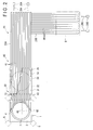
- a blast furnace 1 is installed at an installation site 2
- a furnace body 3 of the blast furnace 1 is constructed onto a base 4, and furnace-body supporting columns 5 are installed surrounding the furnace body 3.
- the furnace body 3 is split into a hearth block 6 and upper ring block(s) 7 and carried-out.
- the ring block 7 is supportably suspended from jacks (not shown) installed at the furnace-body supporting columns 5.
- the carried-out hearth block 6 and ring block 7 are transported to a separately-located work site 8, and individually dismantled.
- the hearth block 6 has a furnace shell 6A on its exterior, and has refractory bricks 6B installed on its inner circumference and underside. Residual iron 6C and pig iron and slag 6D cooled and solidified after the blast furnace 1 is blown-out is deposited on the bottom of the hearth interior.
- the base 4 is made by layering refractory bricks at the installation site.
- the dismantling method for a furnace body of a blast furnace according to the aspect of the invention is employed in the dismantling of the furnace body 3 of the blast furnace 1 described above. In order to use this method, a transporter 10 according to the aspect of the invention is installed in an area from the installation site 2 to the work site 8.
- the transporter 10 includes: a transport route 20 extending from the installation site 2 to the work site 8; a transportation platform 30 slidable on the transport route 20 and having a placement surface 31 on its top surface; a bottom slider 40 formed between the transport route 20 and the underside 32 of the transportation platform 30; and a top slider 50 formed between the placement surface 31 of the transportation platform 30 and the hearth block 6.
- the transport route 20 includes a plurality of base rails 21 arranged in parallel with the lengthwise direction of the transport route 20 and a large number of slide plates 41 paved over their top surface(s).
- the base rails 21, which are each long and steel H-frame members are buried so that their top surfaces will be the same height as the surface of the ground.
- it is preferable that appropriate reinforcement is conducted with respect to the ground where the base rails 21 are to be buried. Suitable existing civil engineering techniques may be applied in the reinforcement of the ground or the burying of the base rails 21.
- the slide plates 41 which are short and plate-like panels, are tightly attached to the top surface of the base rails 21 and sequentially linked so that there is no difference in height between their surfaces.
- the slide plates 41 provide the bottom slider 40.
- the transport route 20 includes two sectional transport routes 20A and 20B.
- the sectional transport routes 20A and 20B which are each linearly shaped, are placed such that the sectional transport route 20B is orthogonally linked to the downstream end of the sectional transport route 20A (at the end remotely away from the installation site 2) with the entire arrangement having an L shape.
- This configuration is employed when a linear route cannot be used to connect the installation site 2 with the work site 8.
- a single and linear transport route may be installed without using the sectional transport routes.
- Tractors 29 are provided at the downstream extensions of the sectional transport routes 20A and 20B.
- the tractors 29A and 29B include one or a plurality of traction mechanisms.
- the traction mechanisms are winches or the like, with each being connected to the transportation platform 30 via wires 28 (28A and 28B).
- the traction mechanisms are arranged in pairs on both sides with respect to the width direction of the transport routes 20A and 20B (the width direction of the transportation platform 30).
- the transportation platform 30 is transported over the transport route 20 by pulling the transportation platform 30 with the tractors 29 (each of the winches and wires 28).
- the transportation platform 30 can be transported from the installation site 2 to the work site 8.
- An end of the transport route 20 (sectional transport route 20B) is extended into the interior of the work site 8.
- the transportation platform 30 with the ring block carried on top can be brought into the interior of the work site 8, and the work site 8 is able to house the transportation platform 30 with the ring block carried on its top. It is also possible to construct a new ring block on the top of the transportation platform 30 while the transportation platform 30 remains on the transport route 20 extended into the interior of the work site 8.
- an suitable drive-type traction mechanism such as hydraulic jacks can be used.
- any tractor is usable as long as such a tractor can produce enough drive force to overcome the resistance (friction or similar applied on the bottom slider 40 described later) applied between the transportation platform 30 and the transport route 20.
- one or a plurality of traction mechanisms which may be winches, hydraulic jacks or the like, can be arranged as the tractors 29. When a plurality of traction mechanisms are used, their total drive force should be enough to overcome the resistance applied between the transportation platform 30 and the transport route 20.
- the tractors 29 are preferably arranged with prevention of meandering of the transportation platform 30 also taken into account.
- the tractors when the transportation platform 30 is meandered (i.e., deviated with respect to the direction of movement), the tractors preferably adjust the drive force of a plurality of winches depending on the circumstances and return the direction of movement of the transportation platform 30 to a normal route.
- known measurement techniques are suitably usable. For instance, a linear encoder or similar may be provided on both sides of the transportation platform 30 for detecting displacement from the transport route 20, or a rotary encoder may be provided for measuring the amount of wire 28 wound on the winches on each side. A detailed description of such meander prevention by adjusting the tractors will be given later.
- the transportation platform 30 is a box-shaped structure made from a steel framework or similar, with its top surface being a placement surface 31 upon which a hearth block 6 and ring block 7 can be placed.
- the underside 32 of the transportation platform 30 is supported on the transport route 20 via the bottom slider 40.
- the underside 32 is covered with a plurality of slide plates 42.
- the slide plates 42, together with the slide plates 41 on the transport route 20, provide the bottom slider 40.
- slide plates 51 On the placement surface 31 of the transportation platform 30, a large number of slide plates 51 are arranged in rows, and tractors 39 are provided at a position remotely away from the blast furnace 1.
- the slide plates 51 which are short and plate-like panels, are tightly attached to the placement surface 31 and sequentially linked so that there is no difference in height between their surfaces.
- the slide plates 51 which provides the top sliders 50, are provided continuously into the interior of a later-described cut portion 4A of the base 4.
- the tractors 39 are a pair of winches or the like arranged on both sides of the placement surface 31, and are connected to the hearth block 6 via each of the wires 38. Brackets 6E are mounted on both sides of the hearth block 6, and the wires 38 are connected to these brackets 6E. Accordingly, the hearth block 6 is designed to be transferred from the base 4 to the placement surface 31 by pulling the hearth block 6 with the tractors 39 via the wires 38. Where appropriate, the tractors 39 can employ the same configuration as the tractors 29 described above.
- the bottom slider 40 includes the above-described slide plates 41 on the transportation platform 30 and the slide plates 42 covering the underside 32 of the transportation platform 30. As is shown in Fig. 3 , the facing surfaces of the slide plates 41 and 42 slide against each other when the transportation platform 30 is moved over the transport route 20. Materials for the slide plates 41 and 42 are suitably selected in order to reduce friction resistance during this sliding. According to the present embodiment, the slide plates 41 (longer plates) adjacent to the transport route 20 are made of steel while the slide plates 42 (comparatively shorter plates) adjacent to the transportation platform 30 are made of stainless material.
- the cut portion 4A is formed in the base 4 at a height corresponding to the height of the placement surface 31.
- this cut portion 4A separates the base 4 into a base top portion 4B that is carried-out integrally with the hearth block 6 and a base bottom portion 4C that remains at the installation site 2, and ensures a vacant portion 4D in which top the sliders 50 are provided.
- An intermediate platform 60 is installed between the base 4 and the transportation platform 30, and the top surface of the base bottom portion 4C and the placement surface 31 of the transportation platform 30 are designed to form a single continuous surface via the top surface of this intermediate platform 60.
- the top surface of the base bottom portion 4C, the top surface of the intermediate platform 60 and the placement surface 31 of the transportation platform 30 are covered with panel members that serve as the slide plates 51. By connecting the ends of these surfaces together, a single continuous slide plate 51 is formed. Before the movement of the transportation platform 30, the continuous slide plate 51 is cut at the boundary portion with the intermediate platform 60. The use of a burner or any other suitable method can be employed for the cutting.
- the top sliders 50 include: slide plates 51 reaching from the top surface of the base bottom portion 4C to the top surface of the placement surface 31 and located adjacent to the transportation platform 20; and slide plates 52 adjacent to the underside of the base top portion 4B, i.e., adjacent to the hearth block 6.
- the facing surfaces of the slide plates 51 and 52 slide against each other when the hearth block 6 is transferred to the transportation platform 30.
- Materials for the slide plates 51 and 52 are suitably selected in order to reduce friction resistance during this sliding.
- the slide plates 51 (longer plates) adjacent to the transportation platform 20 are made of steel while the slide plates 52 (comparatively shorter plates) adjacent to the hearth block 6 are made of stainless material.
- Panel members used for the slide plates 41,42,51 and 52 preferably have a panel thickness of 6 to 36mm.
- the hearth block 6 can reach weights of, for instance, 5000 to 8000 tons, and the pressure on the slide surfaces of the slide plates is extremely high.
- the panel members preferably have a panel thickness of 6 mm or more.
- a panel thickness of more than 36 mm is not preferable in terms of cost, and makes it difficult to handle the panel members because of weight. Accordingly, the above-described panel thickness of 6 to 36 mm is preferable.
- fixing methods for fixing the slide plates 41,42,51 and 52 to each of their installation positions There are no particular limitations on fixing methods for fixing the slide plates 41,42,51 and 52 to each of their installation positions.
- Such fixing methods may be suitably selected from, for instance, fastening with a bolt and nut or similar and fixation by welding, with the materials of portions to be joined taken into account.
- a lubricant such as carbon powder or grease is preferably applied to the slide surfaces of the slide plates 41,42,51 and 52.
- the following procedure is employed. First, a plurality of cut sections 4G (see Fig. 2 ) parallel to each other in plan view are prepared, and the below work is conducted with respect to each of the cut sections.
- the base 4 is horizontally cut at a position corresponding to the height of the placement surface 31 to provide a bottom cut surface 4E, and the base 4 is horizontally cut at a position higher than the placement surface 31 by a predetermined height to provide a top cut surface 4F.
- the section between these top and bottom cut surfaces is removed to provide a vacant portion 4D, and the slide plates 51 and 52 are arranged in a pile on the top surface of the bottom cut surface 4E.
- a load support(s) 53 is arranged on the top surface of the slide plates 51 and 52 to fill in the vacant portion 4D.
- a wire sawing is preferably used for horizontally cutting each of the sections 4G. It is preferable that, when a wire saw is used for cutting, horizontal through-holes are first opened in the boundary portion(s) (the dotted lines in Fig. 2 ) of each of the sections 4G for the base.
- a combination arrangement (see Fig. 3 ) of HPA 54 (High Pack Anchor, a fibrous sack filled with mortar) and ⁇ material 55 (a combination of garnets, spherical particles of small diameter, and one or more types of mortar), can be used, but an arrangement using either HPA 54 or ⁇ material 55 alone can also be used.
- HPA 54 High Pack Anchor, a fibrous sack filled with mortar
- ⁇ material 55 a combination of garnets, spherical particles of small diameter, and one or more types of mortar
- JP-A-2006-183105 JP-A-2006-283183 and International Publication No. WO2007/135916 , which are commonly owned by the present applicant, refer to structures including load supports or a slide member usable as the top sliders 50 or bottom sliders 40.
- the techniques therein can also be utilized in the invention where necessary.
- the invention is not limited to these, but may adopt any other configuration as long as such a configuration can provide sufficient load supportability and slidability.
- a furnace body is dismantled by following the below procedure in the present embodiment.
- the transport route 20 is installed in the area from the installation site 2 where the furnace body 3 and the base 4 are installed to the work site 8, and the transportation platform 30 having the placement surface 31 on its top surface is slidably installed on the transport route 20.
- the bottom slider 40 is provided between the transportation platform 30 and the transport route 20.
- the cut portion 4A is formed by cutting the base 4 in a horizontal direction at the height of the placement surface 31, and a hearth block 6 is cut out by cutting (ensuring a gap 7A in Fig. 1 ) the portion between a ring block 7 (the upper portion of the furnace body 3) and the hearth block 6 in the horizontal direction.
- the top slider 50 that leads from the cut portion 4A is provided continuously on the top surface of the intermediate platform 60 and the placement surface 31.
- the hearth block 6 and the base top portion 4B are moved via the top slider 50 in the horizontal direction and placed on top of the placement surface 31.
- the transportation step shown in Fig. 7 the transportation platform 30 mounted with the hearth block 6 and the base top portion 4B is moved along the transport route 20 to the work site 8. At this time, friction between the transportation platform 30 and the transport route 20 is reduced by the bottom slider 40, so that the transportation platform 30 is stably and reliably moved while driven by the tractors 29 (see Figs. 1 and 2 ).
- the transport route 20 according to the present embodiment is provided by linking the sectional transport routes 20A and 20B together. At the section where the sectional transport routes are linked, switching between tractors 29A and 29B is conducted.
- the transportation platform 30 is connected to the tractor 29A by a wire 28A at the upstream side of the sectional transport route 20A (the left side in the figure, side adjoining to the installation site 2), and is pulled from that location to the downstream end of the sectional transport route 20A.
- the transportation platform 30 reaches the downstream end of the sectional transport route 20A, the wire 28A is detached, and the transportation platform 30 is connected by another wire 28B to the tractors 29B.
- the transportation platform 30 is then pulled by the tractors 29B to be transported from the upstream end of the sectional transport route 20B (on the right in the figure) to the work site 8 located at the downstream end of the sectional transport route 20B (on the bottom in the figure).
- the hearth block 6 is placed on top of the transportation platform 30 and the transportation platform 30 is moved along the transport route 20 for the transportation of the hearth block 6.
- the transportation platform 30 can be easily moved using the tractors 29.
- the transport route 20 is installed continuously from the installation site 2 to the work site 8, a desired slidability between the transport route 20 and the transportation platform 30 can be ensured along the entire length of the transport route 20.
- the transportation platform 30 can be reliably moved by simply pulling the platform 30 with the tractors 29, without using guides or similar for changing direction. Furthermore, use of the combination of an existing wire and winch for the tractors 29 can simplify a structure for pulling the transportation platform 30. Because the transport route 20 is provided by linking the sectional transport routes 20A and 20B together, by arranging each of the sectional transport routes 20A and 20B in intersecting directions, the route as a whole can have a bending shape. Thus, a degree of freedom with respect to the location of the installation site 2 and the work site 8 and to the arrangement of the transport route can be ensured while still benefiting from the linear pulling.
- the slide plates 41 and 42 made of steel and stainless material are used as the bottom slider 40 between the transport route 20 and the transportation platform 30, a desired slidability can be ensured with a simplified structure, and facility costs can be reduced.
- the slide plates 51 and 52 made of steel and stainless material are used in the top slider 50 between the transportation platform 30 and the hearth block 6, a desired slidability can be ensured with a simplified structure, and facility costs can be reduced.
- the top slider 50 for the base 4 is provided.
- the work on each of the cut portions 4A is conducted and the load support 53 is used.
- the operations can be conducted stably and reliably.
- the invention is not limited to the above embodiment but includes other embodiments or modifications or the like such as those described below.
- the bottom slider 40 is provided by the slide plates 41 covering the top surface of the base rails 21 of the transport route 20 and the slide plates 42 covering the underside 32 of the transportation platform 30 (see Fig. 3 ) in the above embodiment
- the invention is not limited to this but may be of any other configuration.
- the slide plates 41 adjacent to the transport route 20 are steel panel members and the slide plates 42 adjacent to the transportation platform 30 are panel members made of stainless material in the above embodiment
- the slide plates 41 and the slide plates 42 may be reversely configured.
- the slide plates 41 may be made from stainless material while the slide plates 42 may be made from steel.
- both may be made from steel.
- the transport route 20 side and the transportation platform 30 side of the bottom slider 40 do not each have to be panel-shaped members, and either can be a long member.
- topside flanges of the base rails 21 buried in the ground protrude above ground, and these flanges serve as the slide plates 41 against which the slide plates 42 slide, thereby providing the bottom slider 40.
- the base rails 21 are made of steel while the slide plates 42 are made of stainless material.
- the materials buried in the ground as the transport route 20 are not limited to the steel H-frame base rails 21 (see Figs. 3 and 8 ), but may be a steel frame of another shape.
- the base rails 22 are cylindrical steel members having a square cross-section, of which top surfaces are exposed above ground to function as the slide plates 41. This kind of bottom slider 40 can also be employed.
- the transportation platform 30 preferably employs a meander preventer for preventing meandering of the transportation platform 30 (deviation with respect to the direction of movement).
- the meander preventer may be a software-based meander-prevention system that uses the control of the tractors 29, or a mechanical meander-prevention mechanism provided between the transport route 10 and the transportation platform 30.
- a meander-prevention system that uses the control of the tractors 29 will be explained.
- a plurality of systems of traction mechanisms provided as tractors 29 may pull the transportation platform 30 with unbalanced pulling force or at unbalanced pulling speed, thereby causing either one of the leading right side and the leading left side of the transportation platform 30 to precede the other (i.e., oblique movement of the transportation platform 30).
- the transportation platform 30 is moved along the line of the obliquely-shifted axis and displaced in a direction intersecting with the pulling direction (the lengthwise direction of the transport route 20), i.e., laterally deviated in the width direction of the transport route 20.
- the meander-prevention system prevents oblique movement of the transportation platform 30 by striking the pulling balance among the systems of the traction mechanisms of the tractors 29, and prevents the meandering resultantly caused by such oblique movement.
- Figs. 10 to 12 show an example in which a meander-prevention system using pulling control is employed in the transporter 10 of the above-described first embodiment.
- the transport route 20 and the transportation platform 30 in Fig. 10 have the same configurations as those in Figs. 1 and 2 .
- the tractors 29 include four systems of traction mechanisms juxtaposed in the width direction of the transport route 20.
- the traction mechanisms respectively include winches 291 to 294, and the winches 291 to 294 pulls the transportation platform 30 by respectively winding up wires 281 to 284 .
- winches 291 to 294 respectively include winches 291 to 294
- the winches 291 to 294 pulls the transportation platform 30 by respectively winding up wires 281 to 284 .
- the tractors 29 include: position detectors 295 to 298 for detecting movement amounts of the positions on the transportation platform 30 pulled by the wires 281 to 284; and a traction controller 300 for controlling pulling operations of the winches 291 to 294 with reference to the detected positions.
- a rotary encoder for detecting a rotation angle of a wire-winding shaft may be provided in the winches 291 to 294.
- the wounded amount(s) of the wires 281 to 284 can be calculated from the amount of the rotation of the winding shaft. Based on the wounded amount(s) of the wires, the movement amounts of the pulled positions on the transportation platform 30, to which the wires 281 - 284 are connected, can be detected.
- the position detectors 295 to 298 may directly detect the wounded amounts of the wires 281 to 284 in the winches 291 to 294 with use of an optical displacement detector or the like. Alternatively, the position detectors 295 to 298 may directly detect relative displacement of the transportation platform 30 with respect to the transport route 20 with use of optical, magnetic or other displacement detectors provided in each of the pulled positions on the transportation platform 30.
- the traction controller 300 includes an operation commander 301, an oblique-movement detector 302, and an oblique-movement corrector 303.
- the operation commander 301 gives commands for the activation and pulling operations of the winches 291 to 294 in accordance with a previously-recorded operation program. Calculation process, standard values and the like in the oblique-movement detector 302 and oblique-movement corrector 303 are also stored in the operation commander 301 in advance, and referenced when necessary.
- the movement distances D1 to D4 are all equal, and the deviations dD1 to dD4 are all zero.
- the full line in Fig. 10 when the transportation platform 30 is tilted and its movement axis is inclined, the movement distances D1 to D4 are all different values, and the deviations dD1 to dD4 with respect to the average value DM are all different values other than zero.
- the deviations dD1 to dD4 are values in proportion to their distance from the central region, which provides the average value DM.
- the pulling force and the resistance in the width direction of the transportation platform 30 may be unbalanced, thereby causing a deformation (for example, an arc deformation) in the width direction of the transportation platform 30.
- some of the movement distances Dn and deviations dDn may have unique values that are no longer in proportionate relationships.
- the oblique-movement corrector 303 calculates a correction value for correcting the oblique movement of the transportation platform 30 detected by the oblique-movement detector 302, and corrects the pulling operations of the winches 291 to 294 via the operation commander 301 with use of the same correction value. Specifically, correction values respectively for the systems are calculated using a function f(dDn) based on the deviations dDn detected by the oblique-movement detector 302, and the rotation speeds V1 to V4 of the winches 291 to 294 of the systems are corrected based on the correction values.
- Fig. 12 shows the controlling steps of the winches 291 to 294 with the traction controller 300, and also the correcting steps for that control.
- the operation commander 301 sets the preset initial values of the pulling speed as the speeds V1 to V4 for the systems (Step S01), and then commences the pulling operation by activating the winches 291 to 294 (Process S02).
- the oblique-movement detector 302 detects the movement distances D1 to D4 for the systems from the position detectors 295 to 298 (Process S03), calculates the average value DM for the pulled distance (Process S04), and then calculates deviations dD1 to dD4 for the systems (Process S05).
- the oblique movement is detected by following the above steps S03 to S05.
- the oblique-movement corrector 303 determines the deviations dD1 to dD4 for use in correction by the systems.
- the oblique-movement corrector 303 compares the deviations dD1 to dD4 for the systems with a preset standard value dS. Then, if even one of the absolute values of any system deviation dDn exceeds the standard value dS, the oblique-movement corrector 303 determines that correction is necessary (Step S06).
- the oblique-movement corrector 303 corrects the speed Vn of each system by increasing or reducing the speed Vn by the amount obtained by the function f(dDn) based on the deviation dDn of the system (Step S07).
- the function f used in the correction can be set appropriately in practice. For instance, the function f may simply multiply the value by a factor, or may perform a calculation based on a preset calculation formula.
- the oblique movement is corrected by following the above steps S06 - S07.
- Step S08 the operation commander 301 continues the pulling operations (Step S08).
- the pulling operations are conducted at a new speed Vn when correction has been performed by the oblique-movement corrector 303, or at the original speed Vn when no correction has been performed.
- the operation commander 301 monitors the progress of the pulling, and the oblique-movement detection, oblique-movement correction and the pulling operations are continuously repeated unless the transportation platform 30 reaches the end point of the transport route 20. On the other hand, when the transportation platform 30 reaches the end point, the pulling operations are ended (Step S09).
- the oblique-movement of the transportation platform 30 pulled over the transport route 20 can be prevented, thereby also preventing any meandering of the transportation platform 30 following the oblique movement.
- the correction value f(dDn) is calculated based on the deviation dDn of each of the systems for the speed correction for each of the systems.
- the steps for the correction by the tractors 29 are not limited to the steps in Fig. 12 but may be steps as in Fig. 13 that do not calculate an average value or deviations.
- the operation commander 301 sets the preset initial values for the pulling speed as the speeds V1 to V4 for the systems respectively (Step S11), and then commences the pulling operations by activating the winches 291 to 294 (Process S12).
- the oblique-movement detector 302 detects the movement distances D1 to D4 for the systems respectively from the position detectors 295 to 298 (Process S 13).
- the above steps are the same as in Fig. 12 .
- Fig. 12 In Fig.
- the oblique-movement detector 302 uses the movement distances D1 and D4 for the systems on both outer sides of the transportation platform 30, and determines that the transportation platform 30 is obliquely moved when the absolute value of the difference between the distances
- the foregoing side of the tilted transportation platform 30 is detected by the oblique-movement corrector 303 (Step S15).
- This detection of the foregoing side can be performed by, for example, a comparison of the movement distances D1-D4 of the systems on both outer sides. Specifically, if D1-D4>0, it means that the first system side is foregoing, and that the fourth system side is lagging.
- the oblique-movement corrector 303 corrects the speed of each of the systems based on the determination of the foregoing side.
- Step S16 For example, if the first system side is foregoing, correction is performed so that the winch 291 on the first system side is decelerated while the winch 294 on the fourth system side is accelerated (Step S16). Alternatively, if the fourth system side is foregoing, correction is performed so that the winch 291 on the first system side is accelerated while the winch 294 on the fourth system side is decelerated (Step S 17).
- the correction values for the second system and the third system can be set by proportionally allocating the correction values for the first system and the fourth system in accordance with the distances between each of the systems in their arrangement.
- a controller normally used for control of the winches of the tractors 29 by using a controller normally used for control of the winches of the tractors 29 and simply arranging the controller to additionally perform software-based processing for conducting the oblique-movement detection and the oblique-movement correction, the oblique movement and the meandering can be prevented. Accordingly, compared to a configuration where mechanical meander-prevention mechanisms are additionally provided, installation facilitation and cost reduction can be anticipated.
- an exemplary mechanical meander-prevention mechanism may adopt the below configuration.
- a mechanical meander-prevention mechanism can be provided by changing the height of some of the long members compared to others or by irregularly disposing the long members when viewed in cross-section. With this arrangement, the meander-prevention function of the transportation platform 30 can be ensured. For example, while three base rails 21 are installed at the same height in the configuration in Fig. 8 , the height of the middle rail may be altered either up or down for use as a meander-prevention mechanism.
- Fig. 14 just as in Fig. 8 , three base rails 21 are buried in the ground.
- both of the two side base rails 21 are at the normal ground level (GL)
- the middle base rail 21 is buried in the underside of a groove 24 formed in the ground.
- a spacer 33 having such a width and thickness as to be accommodatable inside the groove 24 is installed on the underside 32 of the transportation platform 30 at the part corresponding to the groove 24.
- the slide plates 41 and 42 are arranged between the base rail 21 in the groove 24 and the underside of the spacer 33 and between the base rails 21 outside the groove 24 and the underside 32.
- the thickness of the spacer 33 is equivalent to the depth of the groove 24 minus the thickness of the slide plates 41 and 42, and each pair of slide plates 41 and 42 (both pairs located inside and outside the groove 24) is adjusted to be in equal contact and to receive an equal amount of load.
- Contact plates 33A are attached to both side surfaces of the spacer 33, and contact plates 24A are attached to the side surfaces of the groove 24 opposed to the side surfaces of the spacer 33.
- the combination of steel panels and stainless panels described above in relation to the bottom slide member can be used for the slide plates 41 and 42 and the contact plates 24A and 33A.
- the slide plates 41 and 42 can provide the sliding required for transportation while supporting the load of the transportation platform 30.
- the groove 24 and the spacer 33 define an irregular shape continuous in the direction of transportation of the transportation platform 30, thereby providing a meander-prevention function to the transportation platform 30. Particularly, when large meander is about to take place, the contact plates 24A and 33A come into contact with each other, thereby preventing any further development of such a meander.
- the depth of the groove 24 and the thickness of the spacer 33 may be determined in a range of, for instance, 30 to 200 mm.
- the groove 24 may be formed in the underside of the transportation platform 30 instead of the ground while the base rail buried in the ground is supported at a higher position. With this arrangement, an irregular profile that is reverse to that in Fig. 14 can provide a meander-prevention mechanism.
- the meander-prevention mechanism for the transportation platform 30 may be of another configuration.
- a large number of base rails 21 configured as in Figs. 8 and 14 are buried in the ground.
- some of the base rails 21 are buried at the normal ground level (GL)
- the middle three base rails 21 are buried in the underside of a concave portion 24B formed in the ground.
- the concave portion 24B has an arc-shaped cross-section. Of the three base rails 21 buried in the relevant section, the middle one is arranged with its top surface horizontal while the two side base rails 21 are arranged with their top surfaces inclined (i.e., the inclination conforms to the inclination of the underside of the concave portion 24B).
- a convex portion 33B conforming to the cross-sectional shape of the concave portion 24B is provided on the underside 32 of the transportation platform 30 at a portion corresponding to the concave portion 24B.
- the arc shape of the underside of the concave portion 24B and the arc shape of the underside of the convex portion 33B are concentric with respect to each other. The distance between the concave portion 24B and the convex portion 33B is maintained constant at all positions.
- the slide plates 41 and 42 are arranged between the base rail 21 in the concave portion 24B and the underside of the convex portion 33B, and between the base rails 21 outside the concave portion 24B and the underside 32.
- the combination of steel panels and stainless panels described above in relation to the bottom slide member is usable for the slide plates 41 and 42.
- the concave portion 24B and the convex portion 33B can provide an uneven shape continuous in the direction of transportation of the transportation platform 30, thereby providing a meander-prevention mechanism to the transportation platform 30. Particularly, when a large meander is about take place, an increased contact pressure is applied to the slide plates 41 attached to the inclined base rails 21 and the slide plates 42 that slide against them, thereby preventing any further development of such a meander.
- the concave portion 24B and the convex portion 33B may be sized to have, for example, a height of 30 to 200 mm and a width of 100 to 300 mm.
- the concave portion 24B and the convex portion 33B may also be arranged in the reverse vertical arrangement.
- a concave portion 24C is formed by digging into the ground from the normal ground level (GL). The convex portion 33C and the concave portion 24C, which have concentric cylindrical surfaces, can maintain a predetermined distance between each other.
- a plurality of base rails 21 is buried in the concave portion 24C, and the slide plates 41 and 42 are arranged between these base rails 21 and the underside 32.
- the combination of steel panels and stainless panels described above in relation to the bottom slide member is usable for the slide plates 41 and 42.
- the concave portion 24C and the convex portion 33C can provide an uneven shape continuous in the direction of transportation of the transportation platform 30, thereby providing a meander-prevention mechanism to the transportation platform 30.
- the concave portion 24C and the convex portion 33C may be sized to have, for example, a height of 30 to 200 mm, and a width of 100 to 300 mm.
- the concave portion 24C and the convex portion 33C may also be arranged in the reverse vertical arrangement.
- a meander-prevention mechanism When a meander-prevention mechanism is arranged as in Figs. 14 , 15 and 16 , it is difficult to change direction of the transportation platform as compared to the arrangement in which the slide plates 41 and 42 are all in sliding contact on the same plane. Thus, it is preferable that a separate interchanger is parallely used for changing between the sectional transport routes 20A and 20B.
- a separate interchanger is parallely used for changing between the sectional transport routes 20A and 20B.
- mechanical meander-prevention mechanisms capable of coping with changing direction the configurations described below can be employed.
- a guide pin 321 is provided on the underside 32 of the transportation platform 30.
- a guide groove 322 (guide groove 322A on the sectional transport route 20A and guide groove 322B on the sectional transport route 20B) is formed in a space 411 between the slide plates 41 (space 411A on the sectional transport route 20A and space 411B on the sectional transport route 20B).
- the guide grooves 322 (3222A and 322B) are formed as recesses in the ground in the spaces 411 (411A and 411B), and both interior side surfaces are covered in contact plates 322C that use steel panels or similar.
- the guide pin 321 is a rod-shaped pin body 321A formed from steel and fitted at its lower end with a cylindrical or ring-shaped contact member 321C via a bearing 321B such as an oil-less metal bearing or ball-bearing.
- the upper end of the pin body 321A is fixed to a part of the structural frame of the transportation platform 30 by fastening with a bolt 321D or the like, or welding or similar.
- the movement direction of the transportation platform 30 pulled or driven over the transport route 20 is restricted to being along the groove 322, which mechanically prevents meandering.
- the contact member 321C of the guide pin 321 inside the guide groove 322 comes into contact with the contact plates 322C on the interior sides of the guide groove 332, thereby suppressing any further displacement.
- the contact member 321C of the guide pin 321 is rotatably attached via the bearing 321B, wear or heat generation or similar due to excessive friction or the like can be prevented even when the contact member 321C comes into contact with the contact plates 322C while the transportation platform 30 is still in motion.
- the guide groove 322 (322A and 322B) for guiding the guide pin 321 is formed on each of the sectional transport routes 20A and 20B, and meander can be prevented throughout the entire length of the transport route 20. Furthermore, as shown in Fig. 17 , notches 411C are formed in the slide plates 41 of the sectional transport route 20A at sections meeting an extension of the guide groove 322B, and the guide groove 322B is extended into the notches 411C. With this arrangement, when the transportation platform 30 that has moved over the sectional transport route 20A is transferred to the sectional transport route 20B, the guide pin 321 can move smoothly into the guide groove 322B through the notches 411C. Accordingly, with the configurations in Figs. 17 and 18 , a mechanical meander-prevention structure can be provided. In addition, the transportation platform 300 can smoothly be transferred between transport routes when sectional transport routes 20A and 20B are used.
- the upper side of the guide pin 321 is fixed to the transportation platform 30, but may be supported in a rotatable manner via a bearing.
- the upper side of the pin body 321A of the guide pin 321 is rotatably supported by two bearings 321E, so that the pin body 321A itself is rotatable.
- the contact member 321C on the lower side may be directly fixed to the pin body 321A.
- the guide pin 321 is preferably installed in such a manner that at least the contact member 321C is rotatable.
- the guide pin may be fixed in a non-rotatable manner.
- one guide pin 321 is guided in the guide groove 322, but a plurality of guide pins and a plurality of guide grooves may be used.
- three guide pins 32 are provided on the underside of the transportation platform 30 at linearly-aligned positions.
- one guide groove 322A is formed in a clearance 411A between the slide plates 41, so that each of the guide pins 321 is guided along the guide groove 322A.
- three guide grooves 322B are formed in clearances 411A between the slide plates 41, so that the guide pins 321 are respectively guided along their corresponding guide groove 322B.
- the guide pins 321 are aligned parallel to the direction of movement on the sectional transport route 20B, so that the guide pins 321 and the guide grooves 322B thereon cannot be expected to provide as much guiding performance as the guide pins 321 and the guide grooves 322A do on the sectional transport route 20A. Nevertheless, with the sectional transport route 20B being shorter than the sectional transport route 20A, the guide pins 321 can still effectively prevent meandering.
- three guide pins 32 are provided on the underside of the transportation platform 30 at such positions as to correspond to the points of a right-angled triangle.
- two guide grooves 322A are formed in clearances 411A between the slide plates 41, so that one of the guide pins 321 is guided along one of the guide grooves 322A while the other two pins are guided along the other guide groove 322A.
- two guide grooves 322B are formed in clearances 411A between the slide plates 41, so that one of the guide pins 321 is guided along one of the guide grooves 322B while the other two pins are guided along the other guide groove 322B.
- notches 411C are formed at two positions corresponding to the two guide grooves 322B respectively.
- the two guide pins 321 lined up in the movement direction are guided by the one guide groove 322A on the sectional transport route 20A, thereby further enhancing the suppression of meandering.
- the two guide pins 321 lined up in the movement direction are also guided by the one guide groove 322B on the sectional transport route 20B as well, thereby further enhancing the suppression of meandering. Accordingly, meandering can be excellently prevented on either of the sectional transport routes 20A and 20B.
- the bottom slider 40 is not necessarily of a configuration in which one surface and another surface actually slide against each other, but may be of a rolling configuration.
- the bottom slider 40 may be of any other configuration as long as friction can be reduced.
- a slide plate 41 may be attached over the top surface of the base rails 21 of the transport route 20, and a plurality of round steel rods or cylinders may be arranged on the top of the slide plate 41 for use as rollers 43.
- the surface of the underside of the transportation platform 30 may roll directly on the rollers 43, or may be attached with a separate steel panel or the like.
- rollers 43 When such rollers 43 are used, the friction can be further reduced, compared to the configuration using the sliding. However, because the rollers are sequentially ejected from the rear side of the transportation platform 30 as a result of rolling, the ejected rollers are required to be cycled to the front side of the transportation platform 30.
- the TIRTANK 44 has a plurality of rollers 44B surrounding a core 44A.
- the rollers 44B of which rotation axes are linked together by an endless component, are cycled while rolling around the core 44A.
- the core 44A is connected to a load member 44D via support members 44C provided on both sides.
- the slide plate 41 is attached over the top surface of the base rails 21, and the TIRTANK 44 are arranged on the slide plate 41 so as to support the underside of the transportation platform 30. Accordingly, while the transportation platform 30 rolls on the transport route 20 with the rollers 44B of the TIRTANK 44, no special work is required as the transportation platform 30 progresses because the rollers 44B in the TIRTANK 44 are cycled by themselves.
- Such TIRTANK 44 considerably increases the height as compared to panels.
- a concave portion is formed in the transport route 20 or the transportation platform 30 so as to accommodate the TIRTANK 44 therein.
- a long member 23 having an open square shaped cross-section is buried in the transport route 20 with its opening facing upwards, thereby providing a concave groove.
- the concave groove which has a width sufficient for accommodating the TIRTANK 44, is somewhat shallower than the height of the TIRTANK44, so that the underside of the transportation platform 30 can be supported by the TIRTANK 44. According to such a configuration, the height dimension of the TIRTANK 44 can be absorbed on the transport route 20 side.
- a concave portion 35 may be formed in the underside of the transportation platform 30, so that the TIRTANK 44 can be accommodated therein.
- the base rails 21 are installed on the transport route 20, such that the TIRTANK 44 can roll over the top surfaces of the base rails 21. According to such a configuration, only a specific portion of the transportation platform 30 is required to be spared for the concave portion for housing the TIRTANK44. Thus, the structure of the transport route 20, which covers a long distance, can be simplified.
- the same configurations as those described above for the bottom slider 40 can be employed in the top slider 50 between the transportation platform 30 and the hearth block 6 or base top portion 4B.
- the load support 53 is preferably provided on the top surface of the top slider 50 so as to bear the load of the hearth body at the time of the horizontal cutting for cutting out the hearth block 6 in the separation step.
- the driving of the transportation platform 30 and the movement of the hearth block 6 may not necessarily be conducted by winding up the wires 28 and 38 with the tractors 29 and 39 but may be conducted with use of any other suitable drive mechanism.
- the transportation platform 30 may be laterally driven by a hydraulic cylinder. Furthermore, the transportation platform 30 is not limitedly used for transporting the hearth block 6 but may be used for transporting other ring blocks 7. In addition, the transportation platform 30 is not limitedly used when the furnace body 3 is dismantled but may be used for transporting ring blocks from a work site to an installation site during construction of a blast furnace.
- Figs. 27 to 32 show a second embodiment of the invention.
- carrying-out of the hearth block 6 according to the aspect of the invention is conducted in the dismantling process for the furnace body 3 in the dismantling of the furnace body 3.
- carrying-in of the hearth block 6 according to the aspect of the invention is conducted in the constructing of the furnace body 3 along with the carrying-out in the dismantling of the furnace body 3.
- the second exemplary embodiment described below uses the same transporter as in the above-described first exemplary embodiment, so that the same reference numerals are used for the same configurations, for which no redundant description will be made.
- the furnace body 3 is constructed on the base 4 at the installation site 2 of the blast furnace 1.
- the furnace body 3 is provided by linking another ring block 7 (furnace top mantle and furnace belly mantle) onto the hearth block 6.
- a new hearth block 6 will be referred to as a hearth block 6N while old hearth block 6 will be referred to as hearth block 6P
- a new ring block(s) 7 will be referred to as ring block(s) 7N while old ring block(s) 7 will be referred to as ring block(s) 7P, for distinction.
- a work site (dismantling work site 8P) is used for dismantling an old hearth block 6P carried-out from the blast furnace 1 while a work site (manufacturing work site 8N) is used for preliminarily manufacturing a hearth block 6N to be newly installed in the furnace body.
- a ring block transporter 10 is installed between the manufacturing work site 8N, the dismantling work site 8P and the installation site 2.
- the transporter 10 which is substantially the same as the one in the first exemplary embodiment described above, includes the transporter 20, the transportation platforms 30 (30N and 30P) and the intermediate platform 60.
- the transport route 20 includes a main transport route 20C extending from the installation site 2 and secondary transport routes 20D branched from the main transport route 20C.
- the dismantling work site 8P and the manufacturing work site 8N are arranged on one side of the main transport route 20C, and the secondary transport routes 20D for each are branched from the same side (the upper side in the figure) of the main transport route 20C.
- the work sites 8P and 8N can be arranged on the opposite side of the main transport route 20C, and the secondary transport routes 20D for each may be branched from the opposite side of the main transport route 20C.
- other ring blocks 7 are transported to and from other work sites with use of existing furnace body transportation vehicles (dollies).
- the locations of other work sites can be selected as appropriate, taking into account the state of use of the surrounding land.
- the configurations and the like for the dollies used for transportation as transporters may be selected as appropriate. The invention is not limited by either of these.
- a relining work for a furnace body of a blast furnace which includes the dismantling and reconstruction of the furnace body.
- the relining work for the furnace body of the blast furnace is started while the blast furnace 1 is in operation.
- the manufacturing work site 8N, the dismantling work site 8P and the transporter 10 are installed in the vicinity of the installation site 2 (the preparation step in the dismantling process group and the preparation step in the construction process group).
- manufacturing of a new hearth block 6N is commenced on the transportation platform 30N (the manufacturing step in the construction process group).
- manufacturing of a new ring block 7N is also commenced at a work site (not shown).
- a timing at which the manufacturing of the blocks is started is preferably determined by taking into account manufacturing periods for the blocks and calculating backwards from a timing when the blast furnace 1 in operation is to be blown-out. More precisely, the above-described cutting of the base 4 and bottom part of the hearth block 6 of the blast furnace 1 is conducted before the blast furnace 1 is blown-out. Then, as will be described below, the furnace body 3 (the part above the hearth block 6) is dismantled after the blast furnace 1 is blown-out, and each of the blocks is subsequently carried-in to the installation site 2 for reconstruction. Accordingly, the timing at which the manufacturing of the blocks is started can be determined such that the timing at which the manufacturing of the blocks are ended coincides with the above-described timing at which the rings are to be carried-in to the installation site 2 for the reconstruction.
- the construction of the new hearth block 6 is proceeded on the transportation platform 30N arranged inside the manufacturing work site 8N until refractory bricks 6B are stacked on the inside of a furnace shell 6A and the interior is filled with bed coke 6E, sleepers 6F and raw materials (coke or ore).
- the new hearth block 6 manufactured at the manufacturing work site 8N is only required to include such components that are necessary for providing the furnace body 3 when the new hearth block 6 is carried-in to the installation site 2 and mutually linked. How many components are to be incorporated at the manufacturing work site 8N can be decided as appropriate in practice. Typically, components such as the furnace shell, internal refractory material and staves are incorporated there.
- the separation of the furnace body 3 is commenced (the separation step in the dismantling process group).
- the certain stage at which the separation is commenced may be a stage at which the estimated time until completion of the manufacturing of the ring blocks at the work sites becomes approximately equal to the estimated time for the dismantling of the furnace body 3 and the carrying-out of the ring blocks described later.
- the blowing-out (cessation of operation) of the blast furnace 1 is commenced prior to the separation of the furnace body 3. Even if the blowing-out of the blast furnace 1 has been commenced, a considerable period of time is required for the furnace 1 to be cooled enough for separation. Accordingly, it is preferable that the preparation for the blowing-out is conducted a certain period of time earlier than the commencement time for the separation of the furnace body 3.
- the old hearth block 6P is carried-out.
- the separated old ring block 7P is suspended from above, and the transportation platform 30P is brought as close as possible to the installation site 2.
- the hearth block 6P is pulled out from the furnace and transferred onto the transportation platform 30P (the transfer step in the dismantling process group).
- the transportation platform 30P is subsequently moved to transport the hearth block to the work site 8P (the transportation step in the dismantling process group).
- the ring blocks 7P having been suspended from above are sequentially brought down and transported by dollies 61 to work sites (not shown).
- the intermediate platform 60 is evacuated, so that the dollies 61 can be brought as close as possible to the installation site 2.
- a direction for removing the ring blocks 7P preferably coincides with the direction for removing the hearth block 6P.
- new ring blocks 7N that have been manufactured at another work site (not shown) are sequentially carried-in.
- the new ring blocks 7N are carried-in with use of the above-described dollies 61 by following a route that is reverse to a route for the carrying-out of the old ring blocks 7P.
- a new hearth block 6N is carried-in to be located under the ring blocks 7N.
- the transport route 10 for use in dismantling has been already prepared (the preparation step in the construction process group).
- the new hearth block 6N which has been manufactured on the transportation platform 30N at the manufacturing work site 8N, is transported to the installation site 2 by moving the transportation platform 30N along the transport route 10 (the transportation step in the construction process group).
- the new hearth block 6N is transferred from the transportation platform 30N onto the base 4 (the transfer step in the construction process group), and the ring blocks 7N, which are previously carried-in and suspended above the base 4, are brought down and sequentially linked to the hearth block 6N (the linking step in the construction process group).
- a new furnace body 3 is constructed at the installation site 2 from the set of the hearth block 6 and ring blocks 7. Then, after the necessary piping and the like are conducted, a test run and operation of the blast furnace 1 is commenced.
- the old hearth block 6P that has been already transported to the dismantling work site 8P and the old ring blocks 7P that have been transported to another work site are each dismantled and placed of as waste.
- the dismantling process group (the preparation step, the separation step, the transfer step and the transportation step) according to the first embodiment is included, the same advantages as in the first embodiment can be obtained. Furthermore, since the construction process group (the manufacturing step, the preparation step, the transportation step, the transfer step and the linking step) is included, the manufacturing of the new hearth block 6N and ring blocks 7N can be conducted at the manufacturing work site 8N separate from the installation site 2. Thus, because blowing-out can be delayed by the amount of time spent for the manufacturing work, the operation period of the blast furnace 1 can be maximized while the non-operation period for relining can be minimized. In addition, by conducting the construction process group in the order according to the invention, the work period for the construction of the furnace body can be shortened.
- all refractory bricks can be installed in the hearth block in advance because there is no weight restriction (thereby shortening a work period by 3 to 5 days).
- the interior of the hearth block can be filled in advance (during a period after the manufacturing of the hearth block and before transportation) with in-furnace materials (sleepers, coke and iron ore) required for start-up of the blast furnace (thereby shortening a work period by 1 to 2 days).
- the work period for relining can be shortened by 4 to 7 days.
- Fig. 32 shows the hearth block 6 being carried-in onto the base 4 in the construction step according to the present embodiment.
- the hearth block 6 is carried-in onto the base 4 with use of substantially the same transporter 10 as the one used for carrying-out the hearth block 6 from the base 4 and shown in Figs. 1 and 2 (the same is true of the other ring blocks 7).
- the carrying-in shown in Fig. 31 and the carrying-out shown in Fig. 1 are different in the transporting direction.
- a tractor 29C is provided on the installation site 2 while adjoining to the base 4. Because the hearth block 6 is to be pulled over the base 4, a tractor 39C is preferably located higher than the top surface of the base 4, and fixed to a column of the furnace-body supporting column 5 located opposite to the transportation platform 30. Where necessary, the tractors 29C and 39C may be of the same configuration as the tractors 29 and 39 according to the first embodiment. Wires 28C and 38C can be suitably provided to connect the tractors 29C and 39C with the transportation platform 30 or the hearth block 6. In this way, by suitably switching a tractor unit, the transporter 10 can be used in both the dismantling process and the construction process.
- the hearth block 6 or ring blocks 7 are horizontally pulled from the top surface of the transportation platform 30 to the top surface of the base 4 of the installation site 2 or vice versa, it is necessary that the top surface of the transportation platform 30 and the top surface of the base 4 be at the same height.
- the top surfaces of the transportation platform 30 and the base 4 is provided with the continuous top sliders 50 in order to facilitate the transportation of the hearth block 6 or the like.
- the height of the top surface of the base 4 is the same both when the hearth block 6 is carried-out from the installation site 2 (dismantling process) and when the hearth block 6 is carried-in to the installation site 2 (construction process).
- the height of the top surface of the base 4 is decided by horizontally cutting the bottom portion of the furnace body 3 to divide the hearth block 6 from the base 4. Accordingly, it is necessary for the height of the base 4 (i.e., the height at which the furnace body 3 is horizontally cut) to be set to match the height of the top surface of the transportation platform 30.
- the height of the top surface of the base 4 is already at the height of the top surface of the transportation platform 30.
- such a base 4 is preferably constructed so that the height of its top surface matches the height of the top surface of the transportation platform 30.
- the invention is applied to the dismantling of the furnace body 3 in the above-described first embodiment and to both the dismantling and reconstruction of the furnace body 3 in the above-described second embodiment, the invention may be applied only to reconstruction with another technique being employed for the dismantling of the furnace body 3. Any modifications and the like are included in the invention, as long as such modifications and the like are directed to attain an object of the invention.
- the invention which relates to a transporter for ring block(s) and a relining method for a furnace body of a blast furnace, is applicable to carrying-in and carrying-out of the ring block(s) in renewing or dismantling the blast furnace, and particularly applicable to effective carrying-in and carrying-out of a hearth block of great weight.
Landscapes
- Engineering & Computer Science (AREA)
- Chemical & Material Sciences (AREA)
- Manufacturing & Machinery (AREA)
- Materials Engineering (AREA)
- Metallurgy (AREA)
- Organic Chemistry (AREA)
- Conveying And Assembling Of Building Elements In Situ (AREA)
- Furnace Housings, Linings, Walls, And Ceilings (AREA)
- Working Measures On Existing Buildindgs (AREA)
- Blast Furnaces (AREA)
- Waste-Gas Treatment And Other Accessory Devices For Furnaces (AREA)
Priority Applications (1)
| Application Number | Priority Date | Filing Date | Title |
|---|---|---|---|
| PL08827140T PL2172569T3 (pl) | 2007-08-09 | 2008-08-05 | Urządzenie do przenoszenia bloku pierścieniowego oraz sposób naprawy obudowy wielkiego pieca |
Applications Claiming Priority (2)
| Application Number | Priority Date | Filing Date | Title |
|---|---|---|---|
| JP2007207734 | 2007-08-09 | ||
| PCT/JP2008/064001 WO2009020111A1 (fr) | 2007-08-09 | 2008-08-05 | Appareil de transport de bloc annulaire et procédé de réparation pour enceinte de haut fourneau |
Publications (3)
| Publication Number | Publication Date |
|---|---|
| EP2172569A1 true EP2172569A1 (fr) | 2010-04-07 |
| EP2172569A4 EP2172569A4 (fr) | 2010-12-08 |
| EP2172569B1 EP2172569B1 (fr) | 2013-03-20 |
Family
ID=40341343
Family Applications (1)
| Application Number | Title | Priority Date | Filing Date |
|---|---|---|---|
| EP08827140A Active EP2172569B1 (fr) | 2007-08-09 | 2008-08-05 | Appareil de transport de bloc annulaire et procédé de réparation pour enceinte de haut fourneau |
Country Status (8)
| Country | Link |
|---|---|
| EP (1) | EP2172569B1 (fr) |
| JP (1) | JP4351288B2 (fr) |
| KR (1) | KR101126120B1 (fr) |
| CN (1) | CN101688256B (fr) |
| BR (1) | BRPI0811412B1 (fr) |
| ES (1) | ES2411130T3 (fr) |
| PL (1) | PL2172569T3 (fr) |
| WO (1) | WO2009020111A1 (fr) |
Cited By (1)
| Publication number | Priority date | Publication date | Assignee | Title |
|---|---|---|---|---|
| EP3029159A1 (fr) * | 2013-07-30 | 2016-06-08 | Nippon Steel & Sumikin Engineering Co., Ltd. | Procédé de réparation de haut fourneau |
Families Citing this family (8)
| Publication number | Priority date | Publication date | Assignee | Title |
|---|---|---|---|---|
| JP5336893B2 (ja) * | 2009-03-18 | 2013-11-06 | 新日鉄住金エンジニアリング株式会社 | 高炉の炉底ブロックの交換方法 |
| CN102618677B (zh) * | 2012-03-21 | 2013-09-18 | 马钢(集团)控股有限公司 | 大型高炉大修炉内物料清理方法 |
| CN103509899A (zh) * | 2012-06-20 | 2014-01-15 | 鞍钢股份有限公司 | 一种长寿型高炉炉缸 |
| CN104499728B (zh) * | 2014-12-25 | 2016-05-11 | 北京国电龙源环保工程有限公司 | 吸收塔平移装置及其施工方法 |
| CN105177202B (zh) * | 2015-10-22 | 2017-08-08 | 安徽马钢工程技术集团有限公司 | 一种炼铁高炉大修方法 |
| JP6845051B2 (ja) * | 2017-03-13 | 2021-03-17 | 東芝インフラシステムズ株式会社 | 運搬装置及び電気盤の設置方法 |
| CN108300825A (zh) * | 2018-05-02 | 2018-07-20 | 安徽马钢设备检修有限公司 | 一种用于高炉炉壳推移用的辊道装置及其推移方法 |
| CN110592300A (zh) * | 2019-08-29 | 2019-12-20 | 上海宝冶冶金工程有限公司 | 高炉炉壳的运输系统及方法 |
Citations (3)
| Publication number | Priority date | Publication date | Assignee | Title |
|---|---|---|---|---|
| EP0182511A1 (fr) * | 1984-10-30 | 1986-05-28 | Davy Mckee (Stockton) Limited | Procédé de construction d'un haut-fourneau |
| EP1041162A1 (fr) * | 1999-03-31 | 2000-10-04 | Kawasaki Steel Corporation | Procédé de construction d'un haut fourneau et dispositif de levage transférable |
| EP1048741A1 (fr) * | 1999-04-30 | 2000-11-02 | Kawasaki Steel Corporation | Procédé et dispositif pour la rénovation rapide ou construction d'un haut fourneau |
Family Cites Families (4)
| Publication number | Priority date | Publication date | Assignee | Title |
|---|---|---|---|---|
| CN1222579A (zh) * | 1998-12-02 | 1999-07-14 | 酒泉钢铁(集团)有限责任公司 | 高炉大修整装推移技术和装置 |
| JP2006283183A (ja) | 2005-04-05 | 2006-10-19 | Nippon Steel Engineering Co Ltd | 高炉炉体の撤去方法 |
| CN2873705Y (zh) * | 2005-12-27 | 2007-02-28 | 宝山钢铁股份有限公司 | 滑移式高架台车 |
| CN100480398C (zh) * | 2006-12-01 | 2009-04-22 | 莱芜钢铁集团有限公司 | 高炉大修拆装炉自吊装施工方法及炉顶起重装置 |
-
2008
- 2008-07-30 JP JP2008196528A patent/JP4351288B2/ja active Active
- 2008-08-05 CN CN2008800176980A patent/CN101688256B/zh active Active
- 2008-08-05 PL PL08827140T patent/PL2172569T3/pl unknown
- 2008-08-05 ES ES08827140T patent/ES2411130T3/es active Active
- 2008-08-05 EP EP08827140A patent/EP2172569B1/fr active Active
- 2008-08-05 KR KR1020097024508A patent/KR101126120B1/ko active IP Right Grant
- 2008-08-05 BR BRPI0811412A patent/BRPI0811412B1/pt active IP Right Grant
- 2008-08-05 WO PCT/JP2008/064001 patent/WO2009020111A1/fr active Application Filing
Patent Citations (3)
| Publication number | Priority date | Publication date | Assignee | Title |
|---|---|---|---|---|
| EP0182511A1 (fr) * | 1984-10-30 | 1986-05-28 | Davy Mckee (Stockton) Limited | Procédé de construction d'un haut-fourneau |
| EP1041162A1 (fr) * | 1999-03-31 | 2000-10-04 | Kawasaki Steel Corporation | Procédé de construction d'un haut fourneau et dispositif de levage transférable |
| EP1048741A1 (fr) * | 1999-04-30 | 2000-11-02 | Kawasaki Steel Corporation | Procédé et dispositif pour la rénovation rapide ou construction d'un haut fourneau |
Non-Patent Citations (2)
| Title |
|---|
| FUJITA M ET AL: "SHORT TERM REVAMPING OF NO. 6 BLAST FURNACE IN CHIBA WORKS" REVUE DE METALLURGIE - CAHIERS D'INFORMATIONS TECHNIQUES, REVUE DE METALLURGIE. PARIS, FR, vol. 96, no. 3, 1 March 1999 (1999-03-01), pages 349-357, XP000828699 ISSN: 0035-1563 * |
| See also references of WO2009020111A1 * |
Cited By (2)
| Publication number | Priority date | Publication date | Assignee | Title |
|---|---|---|---|---|
| EP3029159A1 (fr) * | 2013-07-30 | 2016-06-08 | Nippon Steel & Sumikin Engineering Co., Ltd. | Procédé de réparation de haut fourneau |
| EP3029159A4 (fr) * | 2013-07-30 | 2017-04-05 | Nippon Steel & Sumikin Engineering Co., Ltd. | Procédé de réparation de haut fourneau |
Also Published As
| Publication number | Publication date |
|---|---|
| CN101688256A (zh) | 2010-03-31 |
| BRPI0811412B1 (pt) | 2017-05-02 |
| JP4351288B2 (ja) | 2009-10-28 |
| JP2009062613A (ja) | 2009-03-26 |
| ES2411130T3 (es) | 2013-07-04 |
| EP2172569B1 (fr) | 2013-03-20 |
| PL2172569T3 (pl) | 2013-08-30 |
| WO2009020111A1 (fr) | 2009-02-12 |
| EP2172569A4 (fr) | 2010-12-08 |
| KR101126120B1 (ko) | 2012-03-29 |
| BRPI0811412A2 (pt) | 2015-12-15 |
| CN101688256B (zh) | 2011-07-13 |
| KR20090130417A (ko) | 2009-12-23 |
Similar Documents
| Publication | Publication Date | Title |
|---|---|---|
| EP2172569B1 (fr) | Appareil de transport de bloc annulaire et procédé de réparation pour enceinte de haut fourneau | |
| US6260270B1 (en) | Method and apparatus for short-term relining or construction of blast furnace | |
| US6640963B2 (en) | Device for conveying massive objects, in particular metal reels | |
| RU2618978C1 (ru) | Способ реконструкции доменной печи | |
| JP3165362B2 (ja) | 高炉の短期改修・建設方法 | |
| US8622656B2 (en) | Apparatus, systems and methods for the relocation of subsurface conduit | |
| EP1041162A1 (fr) | Procédé de construction d'un haut fourneau et dispositif de levage transférable | |
| JP4841809B2 (ja) | 高炉建設方法 | |
| KR200395878Y1 (ko) | 원주형 철근구조물용 철근가공장치의 이동대차구조 | |
| US20160238279A1 (en) | Methods of processing a furnace | |
| CN219933357U (zh) | 管道内衬施工设备 | |
| CN218908754U (zh) | 一种楼层板生产线 | |
| JP2001207204A (ja) | 高炉の改修方法 | |
| JPH0754024A (ja) | 溶鉱炉の炉底構造 | |
| JP2001131617A (ja) | 高炉の改修方法 | |
| JP4064002B2 (ja) | 高炉の炉体マンテルの解体方法 | |
| CN116221535A (zh) | 管道内衬施工设备及其施工方法 | |
| JP4530841B2 (ja) | 熱風環状管の設置方法 | |
| JP6647789B2 (ja) | 貯蔵容器の搬入方法 | |
| JP2021191939A (ja) | トンネル下半部セグメントの組立装置および組立方法 | |
| JP6321394B2 (ja) | 壁パネルの設置方法及び壁パネルの搬送装置 | |
| CN112172845A (zh) | 同时补偿水平和垂直偏差的倾斜运动平台 | |
| JP4577910B1 (ja) | 搬送装置、搬送システムおよび被搬送物の搬送方法 | |
| JP2000247589A (ja) | プラント機器取替方法および装置 | |
| JP2001181716A (ja) | 高炉炉体リングブロック工法における炉体リングブロック用吊換装置の基礎補強方法および基礎補強構造 |
Legal Events
| Date | Code | Title | Description |
|---|---|---|---|
| PUAI | Public reference made under article 153(3) epc to a published international application that has entered the european phase |
Free format text: ORIGINAL CODE: 0009012 |
|
| 17P | Request for examination filed |
Effective date: 20100121 |
|
| AK | Designated contracting states |
Kind code of ref document: A1 Designated state(s): AT BE BG CH CY CZ DE DK EE ES FI FR GB GR HR HU IE IS IT LI LT LU LV MC MT NL NO PL PT RO SE SI SK TR |
|
| AX | Request for extension of the european patent |
Extension state: AL BA MK RS |
|
| DAX | Request for extension of the european patent (deleted) | ||
| A4 | Supplementary search report drawn up and despatched |
Effective date: 20101105 |
|
| 17Q | First examination report despatched |
Effective date: 20110920 |
|
| REG | Reference to a national code |
Ref country code: DE Ref legal event code: R079 Ref document number: 602008023077 Country of ref document: DE Free format text: PREVIOUS MAIN CLASS: C21B0007000000 Ipc: C21B0007020000 |
|
| RIC1 | Information provided on ipc code assigned before grant |
Ipc: C21B 7/00 20060101ALI20120321BHEP Ipc: C21B 7/02 20060101AFI20120321BHEP |
|
| GRAJ | Information related to disapproval of communication of intention to grant by the applicant or resumption of examination proceedings by the epo deleted |
Free format text: ORIGINAL CODE: EPIDOSDIGR1 |
|
| GRAP | Despatch of communication of intention to grant a patent |
Free format text: ORIGINAL CODE: EPIDOSNIGR1 |
|
| GRAP | Despatch of communication of intention to grant a patent |
Free format text: ORIGINAL CODE: EPIDOSNIGR1 |
|
| GRAJ | Information related to disapproval of communication of intention to grant by the applicant or resumption of examination proceedings by the epo deleted |
Free format text: ORIGINAL CODE: EPIDOSDIGR1 |
|
| GRAP | Despatch of communication of intention to grant a patent |
Free format text: ORIGINAL CODE: EPIDOSNIGR1 |
|
| RAP1 | Party data changed (applicant data changed or rights of an application transferred) |
Owner name: NIPPON STEEL & SUMITOMO METAL CORPORATION Owner name: NIPPON STEEL ENGINEERING CO., LTD |
|
| GRAS | Grant fee paid |
Free format text: ORIGINAL CODE: EPIDOSNIGR3 |
|
| GRAA | (expected) grant |
Free format text: ORIGINAL CODE: 0009210 |
|
| AK | Designated contracting states |
Kind code of ref document: B1 Designated state(s): AT BE BG CH CY CZ DE DK EE ES FI FR GB GR HR HU IE IS IT LI LT LU LV MC MT NL NO PL PT RO SE SI SK TR |
|
| RAP1 | Party data changed (applicant data changed or rights of an application transferred) |
Owner name: NIPPON STEEL & SUMITOMO METAL CORPORATION Owner name: NIPPON STEEL & SUMIKIN ENGINEERING CO., LTD. |
|
| REG | Reference to a national code |
Ref country code: GB Ref legal event code: FG4D |
|
| REG | Reference to a national code |
Ref country code: CH Ref legal event code: EP |
|
| REG | Reference to a national code |
Ref country code: IE Ref legal event code: FG4D |
|
| REG | Reference to a national code |
Ref country code: AT Ref legal event code: REF Ref document number: 602150 Country of ref document: AT Kind code of ref document: T Effective date: 20130415 |
|
| REG | Reference to a national code |
Ref country code: SE Ref legal event code: TRGR |
|
| REG | Reference to a national code |
Ref country code: DE Ref legal event code: R096 Ref document number: 602008023077 Country of ref document: DE Effective date: 20130529 |
|
| REG | Reference to a national code |
Ref country code: RO Ref legal event code: EPE |
|
| REG | Reference to a national code |
Ref country code: NL Ref legal event code: T3 |
|
| REG | Reference to a national code |
Ref country code: ES Ref legal event code: FG2A Ref document number: 2411130 Country of ref document: ES Kind code of ref document: T3 Effective date: 20130704 |
|
| PG25 | Lapsed in a contracting state [announced via postgrant information from national office to epo] |
Ref country code: NO Free format text: LAPSE BECAUSE OF FAILURE TO SUBMIT A TRANSLATION OF THE DESCRIPTION OR TO PAY THE FEE WITHIN THE PRESCRIBED TIME-LIMIT Effective date: 20130620 Ref country code: BG Free format text: LAPSE BECAUSE OF FAILURE TO SUBMIT A TRANSLATION OF THE DESCRIPTION OR TO PAY THE FEE WITHIN THE PRESCRIBED TIME-LIMIT Effective date: 20130620 Ref country code: LT Free format text: LAPSE BECAUSE OF FAILURE TO SUBMIT A TRANSLATION OF THE DESCRIPTION OR TO PAY THE FEE WITHIN THE PRESCRIBED TIME-LIMIT Effective date: 20130320 |
|
| REG | Reference to a national code |
Ref country code: LT Ref legal event code: MG4D |
|
| PG25 | Lapsed in a contracting state [announced via postgrant information from national office to epo] |
Ref country code: GR Free format text: LAPSE BECAUSE OF FAILURE TO SUBMIT A TRANSLATION OF THE DESCRIPTION OR TO PAY THE FEE WITHIN THE PRESCRIBED TIME-LIMIT Effective date: 20130621 Ref country code: LV Free format text: LAPSE BECAUSE OF FAILURE TO SUBMIT A TRANSLATION OF THE DESCRIPTION OR TO PAY THE FEE WITHIN THE PRESCRIBED TIME-LIMIT Effective date: 20130320 Ref country code: SI Free format text: LAPSE BECAUSE OF FAILURE TO SUBMIT A TRANSLATION OF THE DESCRIPTION OR TO PAY THE FEE WITHIN THE PRESCRIBED TIME-LIMIT Effective date: 20130320 |
|
| REG | Reference to a national code |
Ref country code: PL Ref legal event code: T3 |
|
| PG25 | Lapsed in a contracting state [announced via postgrant information from national office to epo] |
Ref country code: HR Free format text: LAPSE BECAUSE OF FAILURE TO SUBMIT A TRANSLATION OF THE DESCRIPTION OR TO PAY THE FEE WITHIN THE PRESCRIBED TIME-LIMIT Effective date: 20130320 |
|
| PG25 | Lapsed in a contracting state [announced via postgrant information from national office to epo] |
Ref country code: EE Free format text: LAPSE BECAUSE OF FAILURE TO SUBMIT A TRANSLATION OF THE DESCRIPTION OR TO PAY THE FEE WITHIN THE PRESCRIBED TIME-LIMIT Effective date: 20130320 Ref country code: PT Free format text: LAPSE BECAUSE OF FAILURE TO SUBMIT A TRANSLATION OF THE DESCRIPTION OR TO PAY THE FEE WITHIN THE PRESCRIBED TIME-LIMIT Effective date: 20130722 Ref country code: IS Free format text: LAPSE BECAUSE OF FAILURE TO SUBMIT A TRANSLATION OF THE DESCRIPTION OR TO PAY THE FEE WITHIN THE PRESCRIBED TIME-LIMIT Effective date: 20130720 Ref country code: CZ Free format text: LAPSE BECAUSE OF FAILURE TO SUBMIT A TRANSLATION OF THE DESCRIPTION OR TO PAY THE FEE WITHIN THE PRESCRIBED TIME-LIMIT Effective date: 20130320 Ref country code: SK Free format text: LAPSE BECAUSE OF FAILURE TO SUBMIT A TRANSLATION OF THE DESCRIPTION OR TO PAY THE FEE WITHIN THE PRESCRIBED TIME-LIMIT Effective date: 20130320 |
|
| PG25 | Lapsed in a contracting state [announced via postgrant information from national office to epo] |
Ref country code: CY Free format text: LAPSE BECAUSE OF FAILURE TO SUBMIT A TRANSLATION OF THE DESCRIPTION OR TO PAY THE FEE WITHIN THE PRESCRIBED TIME-LIMIT Effective date: 20130320 |
|
| PLBE | No opposition filed within time limit |
Free format text: ORIGINAL CODE: 0009261 |
|
| STAA | Information on the status of an ep patent application or granted ep patent |
Free format text: STATUS: NO OPPOSITION FILED WITHIN TIME LIMIT |
|
| PG25 | Lapsed in a contracting state [announced via postgrant information from national office to epo] |
Ref country code: DK Free format text: LAPSE BECAUSE OF FAILURE TO SUBMIT A TRANSLATION OF THE DESCRIPTION OR TO PAY THE FEE WITHIN THE PRESCRIBED TIME-LIMIT Effective date: 20130320 |
|
| 26N | No opposition filed |
Effective date: 20140102 |
|
| REG | Reference to a national code |
Ref country code: CH Ref legal event code: PL |
|
| REG | Reference to a national code |
Ref country code: DE Ref legal event code: R097 Ref document number: 602008023077 Country of ref document: DE Effective date: 20140102 |
|
| PG25 | Lapsed in a contracting state [announced via postgrant information from national office to epo] |
Ref country code: MC Free format text: LAPSE BECAUSE OF FAILURE TO SUBMIT A TRANSLATION OF THE DESCRIPTION OR TO PAY THE FEE WITHIN THE PRESCRIBED TIME-LIMIT Effective date: 20130320 Ref country code: CH Free format text: LAPSE BECAUSE OF NON-PAYMENT OF DUE FEES Effective date: 20130831 Ref country code: LI Free format text: LAPSE BECAUSE OF NON-PAYMENT OF DUE FEES Effective date: 20130831 |
|
| REG | Reference to a national code |
Ref country code: IE Ref legal event code: MM4A |
|
| PG25 | Lapsed in a contracting state [announced via postgrant information from national office to epo] |
Ref country code: IE Free format text: LAPSE BECAUSE OF NON-PAYMENT OF DUE FEES Effective date: 20130805 |
|
| PG25 | Lapsed in a contracting state [announced via postgrant information from national office to epo] |
Ref country code: MT Free format text: LAPSE BECAUSE OF FAILURE TO SUBMIT A TRANSLATION OF THE DESCRIPTION OR TO PAY THE FEE WITHIN THE PRESCRIBED TIME-LIMIT Effective date: 20130320 |
|
| PG25 | Lapsed in a contracting state [announced via postgrant information from national office to epo] |
Ref country code: HU Free format text: LAPSE BECAUSE OF FAILURE TO SUBMIT A TRANSLATION OF THE DESCRIPTION OR TO PAY THE FEE WITHIN THE PRESCRIBED TIME-LIMIT; INVALID AB INITIO Effective date: 20080805 Ref country code: LU Free format text: LAPSE BECAUSE OF NON-PAYMENT OF DUE FEES Effective date: 20130805 |
|
| REG | Reference to a national code |
Ref country code: FR Ref legal event code: PLFP Year of fee payment: 9 |
|
| REG | Reference to a national code |
Ref country code: FR Ref legal event code: PLFP Year of fee payment: 10 |
|
| REG | Reference to a national code |
Ref country code: FR Ref legal event code: PLFP Year of fee payment: 11 |
|
| REG | Reference to a national code |
Ref country code: DE Ref legal event code: R082 Ref document number: 602008023077 Country of ref document: DE Representative=s name: WESTPHAL, MUSSGNUG & PARTNER PATENTANWAELTE MI, DE Ref country code: DE Ref legal event code: R081 Ref document number: 602008023077 Country of ref document: DE Owner name: NIPPON STEEL CORPORATION, JP Free format text: FORMER OWNERS: NIPPON STEEL & SUMIKIN ENGINEERING CO., LTD., TOKYO, JP; NIPPON STEEL & SUMITOMO METAL CORPORATION, TOKYO, JP Ref country code: DE Ref legal event code: R081 Ref document number: 602008023077 Country of ref document: DE Owner name: NIPPON STEEL & SUMIKIN ENGINEERING CO., LTD., JP Free format text: FORMER OWNERS: NIPPON STEEL & SUMIKIN ENGINEERING CO., LTD., TOKYO, JP; NIPPON STEEL & SUMITOMO METAL CORPORATION, TOKYO, JP |
|
| PGFP | Annual fee paid to national office [announced via postgrant information from national office to epo] |
Ref country code: PL Payment date: 20210629 Year of fee payment: 14 Ref country code: NL Payment date: 20210716 Year of fee payment: 14 |
|
| PGFP | Annual fee paid to national office [announced via postgrant information from national office to epo] |
Ref country code: IT Payment date: 20210712 Year of fee payment: 14 Ref country code: AT Payment date: 20210726 Year of fee payment: 14 Ref country code: FI Payment date: 20210809 Year of fee payment: 14 Ref country code: FR Payment date: 20210715 Year of fee payment: 14 |
|
| PGFP | Annual fee paid to national office [announced via postgrant information from national office to epo] |
Ref country code: ES Payment date: 20210903 Year of fee payment: 14 Ref country code: GB Payment date: 20210701 Year of fee payment: 14 Ref country code: BE Payment date: 20210716 Year of fee payment: 14 Ref country code: RO Payment date: 20210720 Year of fee payment: 14 Ref country code: TR Payment date: 20210804 Year of fee payment: 14 Ref country code: SE Payment date: 20210810 Year of fee payment: 14 Ref country code: DE Payment date: 20210630 Year of fee payment: 14 |
|
| REG | Reference to a national code |
Ref country code: FI Ref legal event code: PCE Owner name: NIPPON STEEL ENGINEERING CO., LTD. Ref country code: FI Ref legal event code: PCE Owner name: NIPPON STEEL & SUMITOMO METAL CORPORATION |
|
| REG | Reference to a national code |
Ref country code: DE Ref legal event code: R119 Ref document number: 602008023077 Country of ref document: DE |
|
| REG | Reference to a national code |
Ref country code: SE Ref legal event code: EUG |
|
| REG | Reference to a national code |
Ref country code: NL Ref legal event code: MM Effective date: 20220901 |
|
| REG | Reference to a national code |
Ref country code: AT Ref legal event code: MM01 Ref document number: 602150 Country of ref document: AT Kind code of ref document: T Effective date: 20220805 |
|
| GBPC | Gb: european patent ceased through non-payment of renewal fee |
Effective date: 20220805 |
|
| PG25 | Lapsed in a contracting state [announced via postgrant information from national office to epo] |
Ref country code: SE Free format text: LAPSE BECAUSE OF NON-PAYMENT OF DUE FEES Effective date: 20220806 Ref country code: RO Free format text: LAPSE BECAUSE OF NON-PAYMENT OF DUE FEES Effective date: 20220805 Ref country code: FI Free format text: LAPSE BECAUSE OF NON-PAYMENT OF DUE FEES Effective date: 20220805 Ref country code: AT Free format text: LAPSE BECAUSE OF NON-PAYMENT OF DUE FEES Effective date: 20220805 |
|
| REG | Reference to a national code |
Ref country code: BE Ref legal event code: MM Effective date: 20220831 |
|
| PG25 | Lapsed in a contracting state [announced via postgrant information from national office to epo] |
Ref country code: NL Free format text: LAPSE BECAUSE OF NON-PAYMENT OF DUE FEES Effective date: 20220901 |
|
| PG25 | Lapsed in a contracting state [announced via postgrant information from national office to epo] |
Ref country code: IT Free format text: LAPSE BECAUSE OF NON-PAYMENT OF DUE FEES Effective date: 20220805 Ref country code: FR Free format text: LAPSE BECAUSE OF NON-PAYMENT OF DUE FEES Effective date: 20220831 Ref country code: DE Free format text: LAPSE BECAUSE OF NON-PAYMENT OF DUE FEES Effective date: 20230301 |
|
| REG | Reference to a national code |
Ref country code: ES Ref legal event code: FD2A Effective date: 20230927 |
|
| PG25 | Lapsed in a contracting state [announced via postgrant information from national office to epo] |
Ref country code: BE Free format text: LAPSE BECAUSE OF NON-PAYMENT OF DUE FEES Effective date: 20220831 |
|
| PG25 | Lapsed in a contracting state [announced via postgrant information from national office to epo] |
Ref country code: GB Free format text: LAPSE BECAUSE OF NON-PAYMENT OF DUE FEES Effective date: 20220805 Ref country code: ES Free format text: LAPSE BECAUSE OF NON-PAYMENT OF DUE FEES Effective date: 20220806 |
|
| PG25 | Lapsed in a contracting state [announced via postgrant information from national office to epo] |
Ref country code: PL Free format text: LAPSE BECAUSE OF NON-PAYMENT OF DUE FEES Effective date: 20220805 |