EP2171350B1 - Lineare led-lampe - Google Patents
Lineare led-lampe Download PDFInfo
- Publication number
- EP2171350B1 EP2171350B1 EP08773700.3A EP08773700A EP2171350B1 EP 2171350 B1 EP2171350 B1 EP 2171350B1 EP 08773700 A EP08773700 A EP 08773700A EP 2171350 B1 EP2171350 B1 EP 2171350B1
- Authority
- EP
- European Patent Office
- Prior art keywords
- light
- reflector
- light source
- unit
- lamp
- Prior art date
- Legal status (The legal status is an assumption and is not a legal conclusion. Google has not performed a legal analysis and makes no representation as to the accuracy of the status listed.)
- Not-in-force
Links
- 230000003287 optical effect Effects 0.000 claims description 18
- 238000001816 cooling Methods 0.000 claims description 10
- 239000002826 coolant Substances 0.000 claims description 7
- 239000004020 conductor Substances 0.000 claims description 4
- 238000007688 edging Methods 0.000 claims 1
- 230000005855 radiation Effects 0.000 description 9
- 230000004907 flux Effects 0.000 description 7
- 238000011161 development Methods 0.000 description 4
- 230000018109 developmental process Effects 0.000 description 4
- 239000000463 material Substances 0.000 description 3
- 229910052751 metal Inorganic materials 0.000 description 3
- 239000002184 metal Substances 0.000 description 3
- 229910052782 aluminium Inorganic materials 0.000 description 2
- XAGFODPZIPBFFR-UHFFFAOYSA-N aluminium Chemical compound [Al] XAGFODPZIPBFFR-UHFFFAOYSA-N 0.000 description 2
- 239000011521 glass Substances 0.000 description 2
- 229910052736 halogen Inorganic materials 0.000 description 2
- 150000002367 halogens Chemical class 0.000 description 2
- 230000001419 dependent effect Effects 0.000 description 1
- 230000000694 effects Effects 0.000 description 1
- 238000010292 electrical insulation Methods 0.000 description 1
- 238000001704 evaporation Methods 0.000 description 1
- 230000008020 evaporation Effects 0.000 description 1
- 239000012530 fluid Substances 0.000 description 1
- 238000005286 illumination Methods 0.000 description 1
- 230000010354 integration Effects 0.000 description 1
- 239000007788 liquid Substances 0.000 description 1
- 238000009304 pastoral farming Methods 0.000 description 1
- 238000001556 precipitation Methods 0.000 description 1
- 238000000926 separation method Methods 0.000 description 1
Images





Classifications
-
- F—MECHANICAL ENGINEERING; LIGHTING; HEATING; WEAPONS; BLASTING
- F21—LIGHTING
- F21V—FUNCTIONAL FEATURES OR DETAILS OF LIGHTING DEVICES OR SYSTEMS THEREOF; STRUCTURAL COMBINATIONS OF LIGHTING DEVICES WITH OTHER ARTICLES, NOT OTHERWISE PROVIDED FOR
- F21V5/00—Refractors for light sources
- F21V5/02—Refractors for light sources of prismatic shape
-
- F—MECHANICAL ENGINEERING; LIGHTING; HEATING; WEAPONS; BLASTING
- F21—LIGHTING
- F21K—NON-ELECTRIC LIGHT SOURCES USING LUMINESCENCE; LIGHT SOURCES USING ELECTROCHEMILUMINESCENCE; LIGHT SOURCES USING CHARGES OF COMBUSTIBLE MATERIAL; LIGHT SOURCES USING SEMICONDUCTOR DEVICES AS LIGHT-GENERATING ELEMENTS; LIGHT SOURCES NOT OTHERWISE PROVIDED FOR
- F21K9/00—Light sources using semiconductor devices as light-generating elements, e.g. using light-emitting diodes [LED] or lasers
- F21K9/60—Optical arrangements integrated in the light source, e.g. for improving the colour rendering index or the light extraction
- F21K9/68—Details of reflectors forming part of the light source
-
- F—MECHANICAL ENGINEERING; LIGHTING; HEATING; WEAPONS; BLASTING
- F21—LIGHTING
- F21S—NON-PORTABLE LIGHTING DEVICES; SYSTEMS THEREOF; VEHICLE LIGHTING DEVICES SPECIALLY ADAPTED FOR VEHICLE EXTERIORS
- F21S4/00—Lighting devices or systems using a string or strip of light sources
- F21S4/20—Lighting devices or systems using a string or strip of light sources with light sources held by or within elongate supports
- F21S4/28—Lighting devices or systems using a string or strip of light sources with light sources held by or within elongate supports rigid, e.g. LED bars
-
- F—MECHANICAL ENGINEERING; LIGHTING; HEATING; WEAPONS; BLASTING
- F21—LIGHTING
- F21V—FUNCTIONAL FEATURES OR DETAILS OF LIGHTING DEVICES OR SYSTEMS THEREOF; STRUCTURAL COMBINATIONS OF LIGHTING DEVICES WITH OTHER ARTICLES, NOT OTHERWISE PROVIDED FOR
- F21V11/00—Screens not covered by groups F21V1/00, F21V3/00, F21V7/00 or F21V9/00
- F21V11/02—Screens not covered by groups F21V1/00, F21V3/00, F21V7/00 or F21V9/00 using parallel laminae or strips, e.g. of Venetian-blind type
-
- F—MECHANICAL ENGINEERING; LIGHTING; HEATING; WEAPONS; BLASTING
- F21—LIGHTING
- F21V—FUNCTIONAL FEATURES OR DETAILS OF LIGHTING DEVICES OR SYSTEMS THEREOF; STRUCTURAL COMBINATIONS OF LIGHTING DEVICES WITH OTHER ARTICLES, NOT OTHERWISE PROVIDED FOR
- F21V29/00—Protecting lighting devices from thermal damage; Cooling or heating arrangements specially adapted for lighting devices or systems
- F21V29/50—Cooling arrangements
- F21V29/51—Cooling arrangements using condensation or evaporation of a fluid, e.g. heat pipes
-
- F—MECHANICAL ENGINEERING; LIGHTING; HEATING; WEAPONS; BLASTING
- F21—LIGHTING
- F21V—FUNCTIONAL FEATURES OR DETAILS OF LIGHTING DEVICES OR SYSTEMS THEREOF; STRUCTURAL COMBINATIONS OF LIGHTING DEVICES WITH OTHER ARTICLES, NOT OTHERWISE PROVIDED FOR
- F21V29/00—Protecting lighting devices from thermal damage; Cooling or heating arrangements specially adapted for lighting devices or systems
- F21V29/50—Cooling arrangements
- F21V29/70—Cooling arrangements characterised by passive heat-dissipating elements, e.g. heat-sinks
- F21V29/74—Cooling arrangements characterised by passive heat-dissipating elements, e.g. heat-sinks with fins or blades
- F21V29/76—Cooling arrangements characterised by passive heat-dissipating elements, e.g. heat-sinks with fins or blades with essentially identical parallel planar fins or blades, e.g. with comb-like cross-section
- F21V29/763—Cooling arrangements characterised by passive heat-dissipating elements, e.g. heat-sinks with fins or blades with essentially identical parallel planar fins or blades, e.g. with comb-like cross-section the planes containing the fins or blades having the direction of the light emitting axis
-
- F—MECHANICAL ENGINEERING; LIGHTING; HEATING; WEAPONS; BLASTING
- F21—LIGHTING
- F21V—FUNCTIONAL FEATURES OR DETAILS OF LIGHTING DEVICES OR SYSTEMS THEREOF; STRUCTURAL COMBINATIONS OF LIGHTING DEVICES WITH OTHER ARTICLES, NOT OTHERWISE PROVIDED FOR
- F21V29/00—Protecting lighting devices from thermal damage; Cooling or heating arrangements specially adapted for lighting devices or systems
- F21V29/50—Cooling arrangements
- F21V29/70—Cooling arrangements characterised by passive heat-dissipating elements, e.g. heat-sinks
- F21V29/83—Cooling arrangements characterised by passive heat-dissipating elements, e.g. heat-sinks the elements having apertures, ducts or channels, e.g. heat radiation holes
-
- F—MECHANICAL ENGINEERING; LIGHTING; HEATING; WEAPONS; BLASTING
- F21—LIGHTING
- F21V—FUNCTIONAL FEATURES OR DETAILS OF LIGHTING DEVICES OR SYSTEMS THEREOF; STRUCTURAL COMBINATIONS OF LIGHTING DEVICES WITH OTHER ARTICLES, NOT OTHERWISE PROVIDED FOR
- F21V7/00—Reflectors for light sources
- F21V7/0008—Reflectors for light sources providing for indirect lighting
-
- F—MECHANICAL ENGINEERING; LIGHTING; HEATING; WEAPONS; BLASTING
- F21—LIGHTING
- F21V—FUNCTIONAL FEATURES OR DETAILS OF LIGHTING DEVICES OR SYSTEMS THEREOF; STRUCTURAL COMBINATIONS OF LIGHTING DEVICES WITH OTHER ARTICLES, NOT OTHERWISE PROVIDED FOR
- F21V7/00—Reflectors for light sources
- F21V7/005—Reflectors for light sources with an elongated shape to cooperate with linear light sources
-
- F—MECHANICAL ENGINEERING; LIGHTING; HEATING; WEAPONS; BLASTING
- F21—LIGHTING
- F21V—FUNCTIONAL FEATURES OR DETAILS OF LIGHTING DEVICES OR SYSTEMS THEREOF; STRUCTURAL COMBINATIONS OF LIGHTING DEVICES WITH OTHER ARTICLES, NOT OTHERWISE PROVIDED FOR
- F21V15/00—Protecting lighting devices from damage
- F21V15/01—Housings, e.g. material or assembling of housing parts
- F21V15/015—Devices for covering joints between adjacent lighting devices; End coverings
-
- F—MECHANICAL ENGINEERING; LIGHTING; HEATING; WEAPONS; BLASTING
- F21—LIGHTING
- F21V—FUNCTIONAL FEATURES OR DETAILS OF LIGHTING DEVICES OR SYSTEMS THEREOF; STRUCTURAL COMBINATIONS OF LIGHTING DEVICES WITH OTHER ARTICLES, NOT OTHERWISE PROVIDED FOR
- F21V17/00—Fastening of component parts of lighting devices, e.g. shades, globes, refractors, reflectors, filters, screens, grids or protective cages
- F21V17/10—Fastening of component parts of lighting devices, e.g. shades, globes, refractors, reflectors, filters, screens, grids or protective cages characterised by specific fastening means or way of fastening
- F21V17/101—Fastening of component parts of lighting devices, e.g. shades, globes, refractors, reflectors, filters, screens, grids or protective cages characterised by specific fastening means or way of fastening permanently, e.g. welding, gluing or riveting
-
- F—MECHANICAL ENGINEERING; LIGHTING; HEATING; WEAPONS; BLASTING
- F21—LIGHTING
- F21V—FUNCTIONAL FEATURES OR DETAILS OF LIGHTING DEVICES OR SYSTEMS THEREOF; STRUCTURAL COMBINATIONS OF LIGHTING DEVICES WITH OTHER ARTICLES, NOT OTHERWISE PROVIDED FOR
- F21V21/00—Supporting, suspending, or attaching arrangements for lighting devices; Hand grips
- F21V21/02—Wall, ceiling, or floor bases; Fixing pendants or arms to the bases
-
- F—MECHANICAL ENGINEERING; LIGHTING; HEATING; WEAPONS; BLASTING
- F21—LIGHTING
- F21V—FUNCTIONAL FEATURES OR DETAILS OF LIGHTING DEVICES OR SYSTEMS THEREOF; STRUCTURAL COMBINATIONS OF LIGHTING DEVICES WITH OTHER ARTICLES, NOT OTHERWISE PROVIDED FOR
- F21V23/00—Arrangement of electric circuit elements in or on lighting devices
- F21V23/06—Arrangement of electric circuit elements in or on lighting devices the elements being coupling devices, e.g. connectors
-
- F—MECHANICAL ENGINEERING; LIGHTING; HEATING; WEAPONS; BLASTING
- F21—LIGHTING
- F21V—FUNCTIONAL FEATURES OR DETAILS OF LIGHTING DEVICES OR SYSTEMS THEREOF; STRUCTURAL COMBINATIONS OF LIGHTING DEVICES WITH OTHER ARTICLES, NOT OTHERWISE PROVIDED FOR
- F21V7/00—Reflectors for light sources
- F21V7/04—Optical design
- F21V7/06—Optical design with parabolic curvature
-
- F—MECHANICAL ENGINEERING; LIGHTING; HEATING; WEAPONS; BLASTING
- F21—LIGHTING
- F21V—FUNCTIONAL FEATURES OR DETAILS OF LIGHTING DEVICES OR SYSTEMS THEREOF; STRUCTURAL COMBINATIONS OF LIGHTING DEVICES WITH OTHER ARTICLES, NOT OTHERWISE PROVIDED FOR
- F21V7/00—Reflectors for light sources
- F21V7/04—Optical design
- F21V7/08—Optical design with elliptical curvature
-
- F—MECHANICAL ENGINEERING; LIGHTING; HEATING; WEAPONS; BLASTING
- F21—LIGHTING
- F21Y—INDEXING SCHEME ASSOCIATED WITH SUBCLASSES F21K, F21L, F21S and F21V, RELATING TO THE FORM OR THE KIND OF THE LIGHT SOURCES OR OF THE COLOUR OF THE LIGHT EMITTED
- F21Y2103/00—Elongate light sources, e.g. fluorescent tubes
- F21Y2103/10—Elongate light sources, e.g. fluorescent tubes comprising a linear array of point-like light-generating elements
-
- F—MECHANICAL ENGINEERING; LIGHTING; HEATING; WEAPONS; BLASTING
- F21—LIGHTING
- F21Y—INDEXING SCHEME ASSOCIATED WITH SUBCLASSES F21K, F21L, F21S and F21V, RELATING TO THE FORM OR THE KIND OF THE LIGHT SOURCES OR OF THE COLOUR OF THE LIGHT EMITTED
- F21Y2105/00—Planar light sources
-
- F—MECHANICAL ENGINEERING; LIGHTING; HEATING; WEAPONS; BLASTING
- F21—LIGHTING
- F21Y—INDEXING SCHEME ASSOCIATED WITH SUBCLASSES F21K, F21L, F21S and F21V, RELATING TO THE FORM OR THE KIND OF THE LIGHT SOURCES OR OF THE COLOUR OF THE LIGHT EMITTED
- F21Y2115/00—Light-generating elements of semiconductor light sources
- F21Y2115/10—Light-emitting diodes [LED]
Definitions
- the invention relates to a lamp unit and a lighting system with a receptacle for the replaceable attachment of a lamp unit.
- a lamp or lamp unit is understood to mean a product in which an electrical light source is connected to further electrical, optical and mechanical elements to form an inseparable unit. Such a lamp is always intended only as a whole for removable recording on a lamp.
- an LED lamp described with a base for connection to a lamp and a curved rotationally symmetrical reflector, in the focal point for generating a directed light distribution, an LED source is arranged.
- the reflector opening forms a light exit plane of the lamp.
- the LED light source is arranged in the light exit plane.
- the light exit plane is closed by a transparent termination.
- a cooling block is arranged on the side facing away from the reflector of the LED light source and extends in the main emission direction, so that it protrudes from the light exit plane.
- a reflector is formed by a housing having an inner reflective surface.
- the exit region of the reflector is closed by a transparent disc, wherein the disc and the housing are fastened by a clip connection.
- a mounting strip for LED modules is formed in the middle of the pane, which is plugged in and electrically contacted there. The LED modules are arranged in a row in the longitudinal direction of the signal light and aligned in the direction of the reflector.
- US 2006/157724 A1 discloses a lamp unit according to the preamble of claim 1.
- a linear light source unit which differs from punctiform light sources, such as.
- punctiform light sources such as.
- WO2005 / 085706 differs in that the light emission is distributed over a linear range.
- Such a linear light source unit with at least one LED light source can on the one hand be formed by a single LED element (eg LED chip) of linear shape, for example by an elongate OLED, but preferably a plurality of LED light sources are arranged in a row , When referred to hereinafter as a "longitudinal direction", this refers to the longitudinal direction of the linear light source unit.
- the light source unit is arranged at a distance in front of the reflector wall of a reflector so that it emits light, preferably the entire light flux in the direction of the reflector wall, from where the light is reflected to the light exit area. It is in contrast to conventional arrangements of light sources and reflectors, as they are, for example, commercially available as halogen reflector lamps, arranged in the light exit region.
- the main beam direction of the light source unit is thus preferably opposite to the main beam direction of the lamp unit.
- the reflector wall is preferably closed, d. H. in particular in the middle region, to which the main radiation direction of the LED light source unit is directed, without interruption. In this way, the most comprehensive possible reflection and thus efficient utilization of the generated light can be achieved.
- the light intensity distribution of a lamp unit according to the invention in contrast to known rotationally symmetrical lamps, preferably substantially 2-axis symmetrical (ie both the longitudinal and the transverse axis) and can thus be used for a variety of lighting purposes, for example. Flooding, grazing light illumination etc. in areas such as facades, walls, floors, etc.
- the reflector is preferably cylindrical, d. H. formed with in the longitudinal direction substantially the same cross-section. Most preferably, it has substantially the shape of a longitudinally halved hollow cylinder with a preferably symmetrical cross-sectional shape.
- the shape of the reflector surface is selected to achieve optical properties, for example as a parabola, ellipse, etc. In this case, the parabolic focal point or one of the ellipse focal points is preferably arranged at the location of the light source unit.
- the reflector wall is preferably curved, particularly preferably with constant curvature. Alternatively, however, it can also have, for example, prismatic shapes and other structures.
- the exit area of the reflector is the area from which the light of the lamp unit exits.
- the region is substantially planar, for example, as formed between parallel longitudinal edges of the reflector plane.
- the exit region is preferably rectangular, more preferably oblong, d. H. its extension in the longitudinal direction is greater, preferably substantially larger (for example more than 2 times, or even more than 5 times) than the extension in the transverse direction.
- a termination is provided, so that a closed reflector space is formed.
- the termination is transmissive to the passage of light and may, for example, be transparent or translucent.
- the termination of the reflector space is preferably complete, so that the lamp as a whole is dust-tight and particularly preferably even sealed airtight.
- a gas filling for example. Be provided with positive or negative pressure in the interior of the reflector space, if this is advantageous for the operation of the LED light source unit (eg. For cooling, electrical insulation, etc.).
- the lamp is not removable as a lamp unit and has no interior parts to be changed.
- the reflector, the termination and the light source unit are permanently connected to each other.
- the lamp unit is for interchangeable use in a luminaire in which it is always used as a complete unit and replaced as needed.
- the LED light source unit may have a common carrier for a number of linear, ie. H. have LED light sources arranged one behind the other in the longitudinal direction. Preferably, all LED light sources are arranged on a common carrier.
- the carrier preferably also includes electrical conductors for the electrical supply of the light sources. More preferably, it can have electrical components for the electrical supply and control of the LED light sources.
- the carrier may be formed as a board, wherein preferably a board material is to be selected, which has a good thermal conductivity for efficient heat distribution.
- an electrical connection for the electrical supply of the LED light sources is provided on the outside of the lamp unit.
- the connection is preferably detachable, d. H. when installing the lamp in a lamp unit, the electrical connection can be easily made and easily removed when removing.
- the electrical connection is provided as a plug connection, terminal connection or screw connection.
- Particularly preferred is an arrangement of the terminal on an end face of the reflector, d. H. at one of the ends of the lamp.
- a passage for the electrical contacting of the LED light source unit arranged in the interior is preferably provided on the front side.
- the mechanical connection and the electrical connection can be formed by a common element, as is known, for example, from the screw base of conventional incandescent lamps or plug-in sockets of commercially available halogen lamps.
- the mechanical termination preferably comprises a projecting connection tongue which, for example, may have a hole suitable for a screw connection, clamping connection or latching connection.
- Particularly preferred electrical and mechanical connection are provided on at least one end face of the reflector.
- a closure plate with a be provided mechanical connection and an electrical connection.
- the end plate is preferably also permanently connected to the rest of the lamp unit. It can be provided that in each case a mechanical connection, for example.
- a connection tongue is provided at both ends of the reflector, but only on one side of an electrical connection.
- slats are provided for influencing the light distribution in the longitudinal plane, which are arranged transversely to the longitudinal direction of the light source unit.
- the lamellae can be designed as simple, flat lamellae or else as more complex curved shapes.
- the lamellae can parallel to each other, for example.
- d. H. be arranged behind the conclusion.
- they may be on the outside of the unit, i. H. be integrated before the conclusion.
- an integration of lamellar, opaque or reflective separations in the termination is possible.
- the lamellae on the light source unit. If the light source unit comprises a plurality of light sources, the lamellae can be arranged between them. In this way, an alignment of the radiation is already possible at the place of light generation. It is particularly preferred here that the lamellae arranged between the light sources are formed with a reflective surface. Thus, a determination of the light exit angle in the longitudinal planes can still be achieved with high efficiency and at the same time optimum utilization of the light generated by the light source unit.
- a flat, transmitting optical element with a structured, ie not completely planar surface for deflecting the light reflecting from the reflector can be provided.
- the light distribution in the transverse plane is preferably influenced in addition to the distribution achieved by the reflector contour.
- the optical element can in this case, for example, the Increase radiation angle of the light.
- the lamp termination directly forms the optical element, ie no separate optical element is provided, but the termination is formed by the optical element, or the transmitting termination has a desired optical function. It is possible to form the optical element as a linear profile, so that the element, for example. Has a constant in the longitudinal direction of the cross section.
- the element may be provided with a prismatic structure for obtaining a broadened emission.
- the reflector is shaped so that the light of the light source unit is focused in a focal point at a distance in front of the light exit area.
- a bundling can be achieved by a reflector with elliptical contour, in which the light source unit is arranged in the first focal point, so that the light is focused in the second focal point at a distance in front of the light exit area.
- the light distribution achieved in this way is particularly interesting for a large number of possible uses, since in the second focal axis the entire luminous flux of the lamp is concentrated in a linear region. If, for example, a narrow slot is arranged in this focal plane, the lamp radiates essentially all the light through this narrow slot.
- the lamp is not visible from the opposite side, which allows extremely interesting applications in lighting.
- this provides the advantage that the light of the lamp is provided in the focal plane, but due to the distance, the heat generated by electrical power loss in the light generation is not effective there.
- a heat sink is preferably provided on the LED element.
- a heat sink consists, for example, of a good heat-conducting material, for example. Metal, preferably aluminum.
- the surface of the heat sink is preferably enlarged, for example by lamellae and / or structured surface.
- the heat sink expedient, as well as the LED light source unit, elongated shape. He is with the best possible heat transfer as close as possible to attach directly to the LED light source elements or to their support.
- the heat sink protrudes from the lamp unit to to allow effective release of heat into the environment.
- the heat sink projects from the exit area, preferably in the direction of the light emission. If the heat sink in this case of substantially the same width as the carrier of the light source unit, this results in no additional shading.
- the heat sink can be accessible from the outside, for example. Be designed as a handle. Preferably, it has a profile shape over the length of the same cross-section.
- a cooling medium can be provided.
- the heat sink may have a cavity for receiving the cooling medium.
- the cooling medium is preferably fluid, d. H. liquid or gaseous.
- the cavity within the heat sink can be completed, whereby a heat transfer on the heat pipe principle by evaporation of the cooling medium hottest and precipitation is achieved at the coldest point.
- the cavity can also be flowed through.
- the heat sink may have at least one of the end faces a connection for the cooling medium.
- the terminal When installed in a corresponding lamp, the terminal can be coupled to a feeding device of the lamp, so that an effective cooling is made possible in particular by flowing through the heat sink in the longitudinal direction.
- the attachment of the heat sink is preferably carried out in the outlet region at the conclusion.
- the conclusion leaves free a longitudinally extending gap in which the designed as a profile heat sink is arranged.
- the light source unit at the exit region with the main radiation direction in the direction of the reflector for example, in a parabolic or ellipsoidal reflector whose surface is substantially perpendicular to the main emission of the LED light source element in the central region, to a certain shade of light emission.
- This shading can be minimized so that it is acceptable for many applications with a suitable (namely relatively broad) radiation of the LED light source element and a suitable narrow shape thereof.
- the reflector surface in the region directly opposite to the light source unit has a shape with a central elevation, so that light incident from the light source unit is reflected in a direction past the light source unit.
- a described lamp unit is preferably of a handy size, so that it can easily be manually inserted into corresponding lighting units. Further preferred are sizes such as are common for conventional lamps of conventional type.
- the outlet region may have a length of 5-150 cm, preferably 10-60 cm.
- the exit area may also have a width of 2.5-20 cm, preferably about 5-10 cm.
- a lamp unit can be used as described above.
- a corresponding lamp comprises a housing and an electrical connection and a receptacle for the replaceable attachment of the lamp unit.
- the recording allows a mechanical fixation and electrical contacting of the lamp unit.
- a corresponding mechanical connection is connected to a suitable terminal of the lamp unit.
- a corresponding electrical contact is connected to the contact terminal of the lamp unit.
- a corresponding lamp is provided in contrast to the pure lamp unit to the fact that the actual light-generating element - namely the lamp unit - is interchangeable.
- the lamp additional components, such as, electrical supply and control devices, u. a. for connection to a mains voltage. Next switching elements, dimmers, etc. may be provided on the lamp.
- an ellipse-shaped reflector lamp described above is used.
- the lamp has a slot-shaped light exit area on, which lies in the second focal axis of the lamp.
- the housing of the lamp almost completely - namely except for the slit-shaped, preferably particularly narrow light exit area - be closed, yet the full luminous flux can be radiated to the outside.
- a lamp 10 is shown.
- the lamp has a cylindrical reflector 12 made of glass, which is closed at both end sides by end plates 12.
- the reflector may also be made of other materials, for example plastic or metal.
- the reflector 12 has a symmetrical cross-section, with the curved side towards the back of the lamp is aligned.
- the shape of the curvature as explained below, for example, be parabolic or elliptical.
- the figures show the reflector shape in this regard only schematically.
- a rectangular light exit region 16 is formed between its longitudinal edges, which is closed by a transparent glass pane 18.
- the termination 18 may be formed by another material, such as plastic, as long as it is light transmissive.
- the heat sink 20 protrudes at the light exit region 16 in the light exit direction. It is designed as a profile body with several parallel slats made of good heat conducting material, aluminum in the example shown.
- the lamp 10 is designed as a linear lamp with an elongate light exit area.
- the width of the light exit area is about 5 cm.
- the length is relatively short in the example shown for illustrative reasons. For such lamps lengths of 10, 30, 60 and 100 cm (light exit area) are sought.
- the reflector 12 has on the inner side a highly reflective reflector surface 13.
- a LED light source unit 30 is mounted directly on the heat sink 20 in a slot 21 of the lens 18.
- the light source unit 30 is formed as a printed circuit board 26 with high power LEDs 24 mounted thereon. On the circuit board 26 traces for electrical connection of the LEDs 24 are provided.
- the electrical supply takes place from a front end of the lamp 10 ago.
- a screw terminal block 27 is provided, the electrical contacts with a passage (not shown) provided by the end plate 14 and is connected to the circuit board 26.
- the end plate 14 has a connection tongue 34 for the mechanical connection of the lamp 10.
- the terminal tongue 34 is formed as protruding from the end face of the lamp 10 flat metal tab with a fixing hole.
- the lamp 10 can be accommodated in a lamp 100 changeable by an electrical control and operating device 102 is connected to the terminal block 27 and the terminal tabs 34 are connected at both ends with corresponding receptacles on a lamp housing 104, for example.
- the lamp 10 is mechanically attached to the lamp 100 and electrically contacted, so that from the control and operating device 102, which is connected to a mains voltage supply, a suitable for the operation of the lamp 10 voltage is supplied and the lamp 10 to this Way can be controlled.
- Fig. 9a, 9b is a second and in Fig. 10a, 10b a third embodiment of a closure plate shown.
- the connection tongue 34 is also formed horizontally in the longitudinal direction of the lamp, but at the back of the reflector.
- the terminal tongue 34 is perpendicular, provided parallel to the end plate.
- the LED 24 emits light on the reflector 12.
- the entire luminous flux is reflected by the reflector wall 13.
- the reflector wall 13 the light is reflected in the main emission of the lamp 10, ie in the opposite direction of the radiation of the LED 24.
- the very close to the apex of the reflector incident luminous flux is reflected back to the LED 24 and its board 26 so that it in this Area comes to a certain shade. Due to the narrow shape of the board 26, the overall shading effect remains relatively low. Later will be part of Fig. 20a, 20b discussed a way how the shading is further reduced.
- the variant shown is the reflector wall 13 of parabolic shape.
- the LED 24 is arranged in the focal point, so that light emitted there is reflected substantially in parallel and through the lens 18 in essentially passes through in parallel.
- the result is like in Fig. 11b shown in the A-plane a very narrow light distribution curve with maximum light intensity.
- the shape of the reflector surface 13 is an ellipse shape having two focal plane F1 and F2.
- the LED elements 24 are arranged in the upper focal plane F1.
- the light emitted from there is focused in the second focal plane F2 arranged at a distance in front of the light exit region 16.
- a slot-shaped opening 36 may, for example, be provided on a luminaire, so that the luminaire is almost completely closed except for the slot 36.
- a lamp according to the partial view in Fig. 13 is provided for controlling or fixing the light emission angle in the lamp longitudinal direction (B-plane) that at the outlet region 16 of the reflector 12 fins 40 are arranged.
- the lamellae 40 are formed in the example shown as a flat diaphragm, which are arranged parallel to the emission direction of the reflector 12. They have a certain height in the light emission direction, with which the beam angle is defined in the longitudinal direction.
- Fig. 14-16 are arranged on the board 26 between the individual LED elements 24 blades 42. These lamellae serve to limit the width of the light distribution in the longitudinal direction. Depending on the height, the distribution can be set as narrow as desired.
- the fins 42 may be opaque. Particularly preferred is a reflective surface of the fins 42, in particular in conjunction with a curved cross-sectional shape of the fins 42 as in Fig. 16 shown. Since the fins 42 are arranged between the LED elements 24, despite the associated limitation of the width of the radiation, an almost complete utilization of the emitted light can be achieved.
- the radiation characteristic of a lamp as described above can - in addition to the described variation of the shape of the reflector 12 - also influenced by the arrangement of corresponding optical elements in the light exit plane 16.
- transmitting optical elements can be introduced in order to achieve a desired light distribution - bundling, widening, scattering, etc.
- the optical elements may be provided as a separate unit, but more preferably they are provided in the lamp termination 18 itself.
- the surface of the lens 18 according to a first embodiment ( Fig. 17a, 17b ) have a structure with round elevations. As the light distribution curve shows, this makes the broadcast wider than with the mere use of a parabolic reflector.
- a further optical effect can be achieved by the use of a prism structure according to the second embodiment ( Fig. 18a, 18b ) be achieved.
- the prismatic structure of the lens 18 leads to a deflection of the vertically incident rays on both sides, so that the in Fig. 18b shown relatively wide light distribution curve arises.
- the lens 18 diffuse the light also diffusely, so that a diffuse light distribution curve ( Fig. 19b ) arises.
- Fig. 20a, 20b a possible measure is described with which a shadowing of the light reflected by the reflector 12 on the board 26 can be reduced.
- the area of the reflector surface 13, which is decisive for such a shadowed reflection, is the middle region 15.
- the reflector surface 13, which in the remaining region is parabolic in shape, as described above, for example, is parabolic. procured differently at this point.
- an involute shape is formed with a central tip 19.
- FIG Fig. 21a, 21b an alternative in which the reflector 12 only has a cross-sectional area which substantially corresponds to the halving of a symmetrical reflector shape (of course, depending on the desired properties, for example. With parabolic or even fingerlambaigem course of the reflector surface 13). Laterally, the completed reflector space is completed by a flat mirror surface 46. As Fig. 21b shows, the corresponding light intensity distribution is unbalanced. The entire luminous flux of the LED light source passes through an approximately half the size of the lamp termination as in the previously described embodiments.
Landscapes
- Engineering & Computer Science (AREA)
- General Engineering & Computer Science (AREA)
- Physics & Mathematics (AREA)
- Microelectronics & Electronic Packaging (AREA)
- Optics & Photonics (AREA)
- Non-Portable Lighting Devices Or Systems Thereof (AREA)
- Arrangement Of Elements, Cooling, Sealing, Or The Like Of Lighting Devices (AREA)
Description
- Die Erfindung betrifft eine Lampeneinheit und ein Leuchtensystem mit einer Aufnahme für die wechselbare Anbringung einer Lampeneinheit.
- Unter einer Lampe bzw. Lampeneinheit wird ein Produkt verstanden, bei dem eine elektrische Lichtquelle mit weiteren elektrischen, optischen und mechanischen Elementen zu einer untrennbaren Einheit verbunden ist. Eine solche Lampe ist stets nur als ganzes zur wechselbaren Aufnahme an einer Leuchte bestimmt.
- In der
WO2005/085706 ist eine LED-Lampe beschrieben mit einem Sockel zur Anbindung an eine Leuchte und einem gewölbten rotationssymmetrischen Reflektor, in dessen Brennpunkt zur Erzeugung einer gerichteten Lichtverteilung eine LED-Quelle angeordnet ist. Die Reflektoröffnung bildet eine Lichtaustrittsebene der Lampe. Die LED-Lichtquelle ist in der Lichtaustrittsebene angeordnet. Die Lichtaustrittsebene ist durch einen transparenten Abschluß verschlossen. Ein Kühlblock ist auf der dem Reflektor abgewandten Seite der LED-Lichtquelle angeordnet und erstreckt sich in Hauptabstrahlrichtung, so daß er aus der Lichtaustrittsebene hervorsteht. - In der
FR 2 831 647 -
US 2006/157724 A1 offenbart eine Leuchteneinheit nach dem Oberbegriff des Anspruchs 1. - Dokument
WO2005/055328 A1 offenbart eine Lampeneinheit gemäß dem Oberbegriff des Anspruchs 1. - Es ist Aufgabe der Erfindung, eine Lampeneinheit und ein Leuchtensystem hierfür vorzuschlagen, wobei eine hohe Lichtleistung und hohe Lichtintensität erzielbar sind.
- Diese Aufgabe wird gelöst durch eine Lampeneinheit nach Anspruch 1 und ein Leuchtensystem hierfür nach Anspruch 13. Abhängige Ansprüche beziehen sich auf vorteilhafte Ausführungsformen der Erfindung.
- Bei der erfindungsgemäßen Lampeneinheit ist eine linearförmige Lichtquelleneinheit vorgesehen, die sich von punktförmigen Lichtquellen, wie bspw. in der
WO2005/085706 dadurch unterscheidet, daß sich der Lichtaustritt über einen linearen Bereich verteilt. Eine derartige linearförmige Lichtquelleneinheit mit mindestens einer LED-Lichtquelle kann einerseits durch ein einzelnes LED-Element (z. B. LED Chip) von linearer Form gebildet sein, bspw. durch eine längliche OLED, bevorzugt sind aber mehrere LED-Lichtquellen in einer Reihe angeordnet. Wenn im folgenden auf eine "Längsrichtung" Bezug genommen wird, so bezieht sich dies auf die Längsrichtung der linearförmigen Lichtquelleneinheit. - Die Lichtquelleneinheit ist im Abstand vor der Reflektorwandung eines Reflektors so angeordnet, daß sie Licht, bevorzugt den gesamten Lichstrom in Richtung der Reflektorwandung abstrahlt, von wo das Licht zum Lichtaustrittsbereich reflektiert wird. Sie ist hierbei im Gegensatz zu herkömmlichen Anordnungen von Lichtquellen und Reflektoren, wie sie bspw. als Halogen-Reflektorlampen handelsüblich sind, im Lichtaustrittsbereich angeordnet. Die Hauptstrahlrichtung der Lichtquelleneinheit ist damit bevorzugt entgegengesetzt zur Hauptstrahlrichtung der Lampeneinheit. Die Reflektorwandung ist bevorzugt geschlossen, d. h. insbesondere im mittleren Bereich, auf den die Hauptstrahlrichtung der LED-Lichtquelleneinheit gerichtet ist, ohne Unterbrechung. So kann eine möglichst umfassende Reflexion und somit effiziente Ausnutzung des erzeugten Lichts erreicht werden.
- Während eine solche relative Anordnung von LED-Lichtquelle und Reflektor bereits aus der
WO2005/085706 bekannt ist, ergibt sich bei der erfindungsgemäßen Lösung der Vorteil, daß durch die linearförmige Lichtquelleneinheit eine erheblich höhere Lampenleistung verwendet und damit eine größere Lichtleistung erzielt werden kann. Entlang der Längsrichtung läßt sich nämlich eine große Anzahl von Hochleistungs-LEDs anordnen. - Entsprechend ist auch die Lichtstärkeverteilung einer erfindungsgemäßen Lampeneinheit im Gegensatz zu bekannten rotationssymmetrischen Lampen, bevorzugt im wesentlichen 2-achsig symmetrisch (d.h. sowohl zur Längs- als auch zur Querachse) und läßt sich so für vielfältige Beleuchtungszwecke einsetzen, bspw. Flutung, Streiflichtbeleuchtung etc. in Bereichen wie Fassaden, Wänden, Bodenflächen etc.
- Der Reflektor ist bevorzugt zylindrisch, d. h. mit in Längsrichtung im wesentlichen gleichem Querschnitt ausgebildet. Besonders bevorzugt hat er im wesentlichen die Form eines längs halbierten Hohlzylinders mit einer bevorzugt symmetrischen Querschnittsform. Die Form der Reflektorfläche ist zur Erzielung optischer Eigenschaften gewählt, bspw. als Parabel, Ellipse etc. Dabei sind bevorzugt der Parabelbrennpunkt bzw. einer der Ellipsenbrennpunkte an dem Ort der Lichtquelleneinheit angeordnet. Die Reflektorwandung ist bevorzugt gewölbt, besonders bevorzugt mit stetiger Wölbung. Sie kann alternativ aber auch bspw. prismatische Formen und andere Strukturen aufweisen.
- Der Austrittsbereich des Reflektors ist der Bereich, aus dem das Licht der Lampeneinheit austritt. Bevorzugt ist der Bereich im wesentlichen eben, bspw. als zwischen parallel verlaufenden Längskanten des Reflektors gebildete Ebene. Der Austrittsbereich ist bevorzugt rechteckig, besonders bevorzugt länglich, d. h. seine Erstreckung in Längsrichtung ist größer, bevorzugt wesentlich größer (bspw. mehr als 2-fach, oder sogar mehr als 5-fach) als die Erstreckung in Querrichtung.
- Am Austrittsbereich ist ein Abschluß vorgesehen, so daß ein geschlossener Reflektorraum gebildet wird. Der Abschluß ist zum Durchtritt des Lichts transmittierend und kann bspw. transparent oder transluzent ausgebildet sein. Der Abschluß des Reflektorraumes ist bevorzugt vollständig, so daß die Lampe insgesamt staubdicht und besonders bevorzugt sogar luftdicht abgeschlossen ist. Bei luftdichtem Abschluß kann eine Gasfüllung, bspw. auch mit Über- oder Unterdruck im Inneren des Reflektorraums vorgesehen sein, wenn dies für den Betrieb der LED-Lichtquelleneinheit (bspw. für Kühlung, elektrische Isolation etc.) vorteilhaft ist.
- Die Lampe ist als Lampeneinheit nicht demontierbar und weist im Innenraum keine zu wechselnden Teile auf. Der Reflektor, der Abschluß und die Lichtquelleneinheit sind unlösbar miteinander verbunden. Die Lampeneinheit ist zum wechselbaren Einsatz in einer Leuchte vorgesehen, in der sie stets als vollständige Einheit verwendet und bei Bedarf ausgetauscht wird.
- Zur erfindungsgemäßen Lampeneinheit sind eine Anzahl von Weiterbildungen der Erfindung vorgesehen. So kann die LED-Lichtquelleneinheit einen gemeinsamen Träger für eine Anzahl von linear, d. h. in Längsrichtung hintereinander angeordneten LED-Lichtquellen aufweisen. Bevorzugt sind sämtliche LED-Lichtquellen auf einem gemeinsamen Träger angeordnet. Der Träger umfaßt bevorzugt auch elektrische Leiter zur elektrischen Versorgung der Lichtquellen. Weiter bevorzugt kann er elektrische Bauteile zur elektrischen Versorgung und Ansteuerung der LED-Lichtquellen aufweisen. Der Träger kann als Platine ausgebildet sein, wobei bevorzugt ein Platinenmaterial zu wählen ist, das zur effizienten Wärmeverteilung eine gute Wärmeleitfähigkeit aufweist.
- Gemäß einer Weiterbildung der Erfindung ist außen an der Lampeneinheit ein elektrischer Anschluß für die elektrische Versorgung der LED-Lichtquellen vorgesehen. Der Anschluß ist bevorzugt lösbar, d. h. beim Einbau der Lampe in eine Leuchteneinheit kann der elektrische Anschluß leicht hergestellt und beim Ausbau auch leicht wieder getrennt werden. Bevorzugt ist der elektrische Anschluß als Steckanschluß, Klemmanschluß oder Schraubanschluß vorgesehen. Besonders bevorzugt ist eine Anordnung des Anschlusses an einer Stirnseite des Reflektors, d. h. an einem der Enden der Lampe. In diesem Fall ist bevorzugt an der Stirnseite ein Durchtritt für die elektrische Kontaktierung der im Inneren angeordneten LED-Lichtquelleneinheit vorgesehen.
- Ebenso ist es in mechanischer Hinsicht auch bevorzugt, einen lösbaren mechanischen Anschluß zur Anbringung in einer Leuchte vorzusehen. Der mechanische Anschluß und der elektrische Anschluß können durch ein gemeinsames Element gebildet werden, wie dies bspw. vom Schraubsockel herkömmlicher Glühlampen oder Stecksockel handelsüblicher Halogenlampen bekannt ist. Bevorzugt umfaßt der mechanische Abschluß eine vorstehende Anschlußzunge, die bspw. ein für eine Schraub-, Klemm- oder Rastverbindung geeignetes Loch aufweisen kann.
- Besonders bevorzugt sind elektrischer und mechanischer Anschluß an mindestens einer Stirnseite des Reflektors vorgesehen. Hierfür kann dort eine Abschlußplatte mit einem mechanischen Anschluß und einem elektrischen Anschluß vorgesehen sein. Die Abschlußplatte ist bevorzugt ebenfalls unlösbar mit dem Rest der Lampeneinheit verbunden. Es kann vorgesehen sein, daß an beiden Stirnseiten des Reflektors jeweils ein mechanischer Anschluß, bspw. in Form einer Anschlußzunge vorgesehen ist, aber nur an einer Seite ein elektrischer Anschluß.
- Gemäß einer Weiterbildung der Erfindung sind zur Beeinflussung der Lichtverteilung in der Längsebene Lamellen vorgesehen, die quer zur Längsrichtung der Lichtquelleneinheit angeordnet sind. Mit Hilfe der Lamellen ist eine Kontrolle bzw. Festlegung des Lichtausstrahlungswinkels in Lampenlängsrichtung möglich. Die Lamellen können als einfache, plane Lamellen oder auch als komplexere gebogene Formen ausgebildet sein.
- Einerseits ist eine Anordnung von Lamellen am Austrittsbereich möglich. Die Lamellen können parallel nebeneinander bspw. innerhalb der Einheit, d. h. hinter dem Abschluß angeordnet sein. Ebenso können sie an der Außenseite der Einheit, d. h. vor dem Abschluß integriert werden. Alternativ ist auch eine Integration von lamellenförmigen, opaken oder reflektierenden Trennungen in den Abschluß möglich.
- Alternativ oder ergänzend hierzu ist es auch möglich, die Lamellen an der Lichtquelleneinheit anzuordnen. Umfaßt die Lichtquelleneinheit mehrere Lichtquellen, so können die Lamellen zwischen diesen angeordnet werden. Auf diese Weise ist eine Ausrichtung der Abstrahlung bereits am Ort der Lichterzeugung möglich. Besonders bevorzugt ist hierbei, daß die zwischen den Lichtquellen angeordneten Lamellen mit reflektierender Oberfläche ausgebildet sind. So kann eine Festlegung des Lichtaustrittswinkels in der Längsebenen bei dennoch hoher Effizienz und gleichzeitig optimaler Ausnutzung des von der Lichtquelleneinheit erzeugten Lichts erreicht werden.
- Andere Weiterbildungen der Erfindung betreffen eine Beeinflussung der Lichtverteilung durch ein optisches Element am Austrittsbereich. So kann ein flaches, transmittierendes optisches Element mit strukturierter, d. h. nicht vollständiger planer Oberfläche zur Ablenkung des vom Reflektor reflektiernden Lichts vorgesehen sein. Hierdurch wird bevorzugt die Lichtverteilung in der Querebene zusätzlich zu der durch die Reflektorkontur erzielten Verteilung beeinflußt. Das optische Element kann hierbei bspw. den Abstrahlwinkel des Lichts vergrößern. Besonders bevorzugt bildet der Lampenabschluß direkt das optische Element, d. h. es ist kein separates optisches Element vorgesehen, sondern der Abschluß wird durch das optische Element gebildet, bzw. der transmittierende Abschluß weist eine gewünschte optische Funktion auf. Es ist möglich, das optische Element als lineares Profil auszubilden, so daß das Element bspw. einen in Längsrichtung konstanten Querschnitt aufweist. Bspw. kann das Element mit einer Prismenstruktur zur Erzielung einer verbreiterten Abstrahlung versehen sein.
- In einer Weiterbildung der Erfindung ist der Reflektor so geformt, daß das Licht der Lichtquelleneinheit in einem Brennpunkt im Abstand vor dem Lichtaustrittsbereich gebündelt wird. Eine solche Bündelung kann durch einen Reflektor mit Ellipsenkontur erzielt werden, bei dem die Lichtquelleneinheit im ersten Brennpunkt angeordnet ist, so daß das Licht im zweiten Brennpunkt im Abstand vor dem Lichtaustrittsbereich gebündelt wird. Die so erzielte Lichtverteilung ist für eine Vielzahl von Verwendungsmöglichkeiten besonders interessant, da in der zweiten Brennachse der gesamte Lichtstrom der Lampe in einem linearen Bereich gebündelt wird. Wird bspw. in dieser Brennpunktebene ein schmaler Schlitz angeordnet, so strahlt die Lampe im wesentlichen das gesamte Licht durch diesen schmalen Schlitz hindurch. Hierdurch ist einerseits die Lampe von der gegenüberliegenden Seite nicht zu sehen, was äußerst interessante Anwendungen in der Beleuchtung ermöglicht. In technischer Hinsicht ist hierdurch der Vorteil gegeben, daß in der Brennpunktebene das Licht der Lampe bereitgestellt wird, aber aufgrund des Abstandes die durch elektrische Verlustleistung bei der Lichterzeugung erzeugte Wärme dort nicht wirksam wird.
- Andere Weiterbildungen der Erfindung betreffen die Kühlung der Lichtquelleneinheit. Eine solche Kühlung wird für LED-Lichtquellen benötigt, um diese in einem günstigen Arbeitsbereich betreiben zu können. Hierfür ist am LED-Element bevorzugt ein Kühlkörper vorgesehen. Ein solcher Kühlkörper besteht bspw. aus einem gut wärmeleitenden Material, bspw. Metall, bevorzugt Aluminium. Die Oberfläche des Kühlkörpers ist bevorzugt vergrößert, bspw. durch Lamellen und/oder strukturierte Oberfläche. Der Kühlkörper weist zweckmäßig, ebenso wie die LED-Lichtquelleneinheit, längliche Form auf. Er ist mit möglichst gutem Wärmeübergang möglichst nah direkt an den LED-Lichtquellenelementen bzw. an deren Träger anzubringen. Erfindungsgemäß steht der Kühlkörper aus der Lampeneinheit vor, um so eine effektive Abgabe von Wärme in die Umgebung zu ermöglichen. Hierfür kann vorgesehen sein, daß der Kühlkörper vom Austrittsbereich vorsteht, bevorzugt in Richtung der Lichtemission. Ist der Kühlkörper hierbei von im wesentlichen gleicher Breite wie der Träger der Lichtquelleneinheit, so ergibt sich hierdurch keine zusätzliche Verschattung. Der Kühlkörper kann von außen zugänglich, bspw. als Griffleiste ausgebildet sein. Bevorzugt weist er eine Profilform mit über die Länge gleichem Querschnitt auf.
- Für die effektive Kühlung kann ein Kühlmedium vorgesehen sein. Hierfür kann der Kühlkörper eine Kavität zur Aufnahme des Kühlmediums aufweisen. Das Kühlmedium ist bevorzugt fluid, d. h. flüssig oder gasförmig. Die Kavität innerhalb des Kühlkörpers kann abgeschlossen sein, wobei ein Wärmetransport nach dem Heat-Pipe-Prinzip durch Verdunstung des Kühlmediums am heißesten und Niederschlag am kältesten Punkt erzielt wird. Alternativ kann die Kavität auch durchströmbar sein. Hierfür kann der Kühlkörper an mindestens einer der Stirnseiten einen Anschluß für das Kühlmedium aufweisen. Beim Einbau in eine entsprechende Leuchte kann der Anschluß mit einer Zuführvorrichtung der Leuchte gekoppelt werden, so daß eine effektive Kühlung insbesondere durch Durchströmung des Kühlkörpers in Längsrichtung ermöglicht wird.
- Die Anbringung des Kühlkörpers erfolgt bevorzugt im Austrittsbereich an dessen Abschluß. Hier kann vorgesehen sein, daß der Abschluß einen in Längsrichtung verlaufenden Spalt freiläßt, in dem der als Profil ausgebildete Kühlkörper angeordnet ist.
- Bei der beschriebenen Anordnung der Lichtquelleneinheit am Austrittsbereich mit Hauptabstrahlrichtung in Richtung auf den Reflektor kommt es bspw. bei einem Parabol- oder Ellipsoid-Reflektor, dessen Fläche im Mittelbereich im wesentlichen rechtwinklig zur Hauptabstrahlrichtung des LED-Lichtquellenelements steht, zu einer gewissen Verschattung der Lichtabstrahlung. Diese Verschattung kann bei geeigneter (nämlich relativ breiter) Abstrahlung des LED-Lichtquellenelements und einer geeigneten schmalen Form desselben so minimiert werden, daß sie für viele Anwendungsfälle hinnehmbar ist. Um aber eine bessere Ausnutzung auch des direkt in Hauptabstrahlrichtung abgestrahlten Lichts zu erreichen kann vorgesehen sein, daß die Reflektorfläche in dem der Lichtquelleneinheit direkt gegenüberliegenden Bereich eine Form mit einer mittleren Erhebung aufweist, so daß von der Lichtquelleneinheit einfallendes Licht in eine Richtung an der Lichtquelleneinheit vorbei reflektiert wird. Bei einem Reflektor mit symmetrischem Querschnitt ist dies bspw. der mittlere Bereich in der Symmetrieebene, auf den die zentrale optische Achse der Lichtquelleneinheit zeigt. Hier kann der im übrigen Bereich wie beschrieben, bspw. parabolisch ausgeformte Reflektor eine abweichende Form mit einer mittleren Erhebung aufweisen, bspw. eine Evolventenform.
- Eine beschriebene Lampeneinheit ist bevorzugt von handlicher Größe, so daß sie leicht manuell in entsprechende Leuchteneinheiten einsetzbar ist. Weiter bevorzugt sind Größen, wie sie für handelsübliche Lampen herkömmlicher Art gängig sind. So kann bspw. der Austrittsbereich eine Länge von 5-150 cm aufweisen, bevorzugt sind 10-60 cm. Der Austrittsbereich kann zudem eine Breite von 2,5-20 cm, bevorzugt etwa 5-10 cm aufweisen.
- In einem erfindungsgemäßen Leuchtensystem gemäß Anspruch 25 kann eine Lampeneinheit wie oben beschrieben verwendet werden. Eine entsprechende Leuchte umfaßt ein Gehäuse und einen elektrischen Anschluß sowie eine Aufnahme für die wechselbare Anbringung der Lampeneinheit. Die Aufnahme ermöglicht eine mechanische Fixierung und elektrische Kontaktierung der Lampeneinheit. Ein entsprechender mechanischer Anschluß ist mit einem passenden Anschluß der Lampeneinheit verbunden. Ebenso ist eine entsprechende elektrische Kontaktierung mit dem Kontaktanschluß der Lampeneinheit verbunden.
- Eine entsprechende Leuchte ist im Gegensatz zur reinen Lampeneinheit dazu vorgesehen, daß das eigentlich lichterzeugende Element - nämlich die Lampeneinheit - darin wechselbar ist. Weiter kann die Leuchte zusätzliche Bauelemente, wie bspw. elektrische Versorgungs- und Steuergeräte, u. a. zum Anschluß an eine Netzspannung umfassen. Weiter können an der Leuchte Schaltelemente, Dimmer etc. vorgesehen sein.
- In einer besonderen Ausgestaltung wird eine oben beschriebene ellipsenförmige Reflektorlampe verwendet. Hier weist die Leuchte einen schlitzförmigen Lichtaustrittsbereich auf, der in der zweiten Brennpunktachse der Lampe liegt. Auf diese Weise kann das Gehäuse der Leuchte fast vollständig - nämlich bis auf den schlitzförmigen, bevorzugt besonders schmalen Lichtaustrittsbereich - geschlossen sein, wobei dennoch der volle Lichtstrom nach außen abgestrahlt werden kann.
- Nachfolgend werden Ausführungsformen der Erfindung anhand von Zeichnungen näher beschrieben. In den Zeichnungen zeigen:
- Fig. 1a, 1b
- perspektivische Ansichten einer Ausführungsform einer Lampeneinheit;
- Fig. 2
- Seitenansicht, Vorderansicht und Draufsicht der Lampeneinheit aus
Fig. 1a, 1b ; - Fig. 3, 3a
- Querschnittsansichten der Ebene A der Lampe aus
Fig. 2 als zusammengebaute Einheit und in Explosionsdarstellung; - Fig. 4
- eine Längsschnittansicht der Ebene C der Lampe aus
Fig. 2 ; - Fig. 5
- eine perspektivische Explosionsdarstellung der Stirnseite der Lampeneinheit aus
Fig. 1a, 1b ; - Fig. 6
- in perspektivischer Darstellung eine erste Ausführungsform einer Abschlußplatte der Lampeneinheit aus
Fig. 5 ; - Fig. 7
- eine Längsschnittdarstellung der Ebene B aus
Fig. 2 ; - Fig. 8
- eine Rückseitenansicht der Lampe aus
Fig. 1a, 1b ; - Fig. 9a
- in perspektivischer Darstellung eine zweite Ausführungsform einer Abschlußplatte;
- Fig. 9b
- eine Querschnittsansicht der Ebene C aus
Fig. 2 mit der Abschlußplatte ausFig. 9a ; - Fig. 10a
- in perspektivischer Darstellung eine dritte Ausführungsform einer Abschlußplatte;
- Fig. 10b
- eine Längsschnittsansicht der Ebene B aus
Fig. 2 mit der Abschlußplatte ausFig. 10a ; - Fig. 11a
- in Querschnittsansicht (Ebene A) eine erste Ausführungsform einer Reflektorform als Parabolreflektor;
- Fig. 11b
- als Lichtverteilungskurve eine Intensitätsverteilung der Abstrahlung der Lampe aus
Fig. 11a ; - Fig. 12a
- in Querschnittsansicht (Ebene A) eine zweite Ausführungsform einer Reflektorform als Ellipse mit den Brennpunktebenen F1 und F2;
- Fig. 12b
- in perspektivischer Querschnittsansicht eine Anordnung einer Lampe aus
Fig. 12a vor einem schlitzförmigen Lichtaustrittsbereich; - Fig. 13
- in teilweiser Querschnittsansicht (Ebene A) und Längsschnittansicht (Ebene C) eine Ausführungsform einer Lampe mit Lamellen am Austrittsbereich;
- Fig. 14
- in teilweiser Querschnittsansicht (Ebene A) eine Ausführungsform einer Lampe mit Lamellen an der Lichtquelleneinheit;
- Fig. 15, 16
- in teilweiser Längsschnittsansicht (Ebene B) Ausführungsformen von Lamellen zwischen den LED-Lichtquellen;
- Fig. 17a, 17b
- Querschnittsansicht, Draufsicht auf eine Abschlußplatte sowie Lichtverteilungskurve einer Lampe mit einer ersten Ausführungsform eines transmittierenden Abschlusses;
- Fig. 18a, 18b
- Querschnittsansicht, Draufsicht auf eine Abschlußplatte sowie Lichtverteilungskurve einer Lampe mit einer zweiten Ausführungsform eines transmittierenden Abschlusses;
- Fig. 19a, 19b
- Querschnittsansicht, Draufsicht auf eine Abschlußplatte sowie Lichtverteilungskurve einer Lampe mit einer dritten Ausführungsform eines transmittierenden Abschlusses;
- Fig. 20a
- in Querschnittsansicht eine Lampe mit einem in einem Teilbereich als Evolventenform ausgebildeten Reflektor;
- Fig. 20b
- eine vergrößerte Darstellung des Evolventen-Bereichs aus
Fig. 20a ; - Fig. 21a
- in Querschnittsansicht eine weitere Ausführungsform einer Lampe mit einem viertelkreisförmigen Reflektor;
- Fig. 21b
- eine Lichtverteilungskurve der Lampe aus
Fig. 21a und - Fig. 22
- in schematischer Längsschnittdarstellung eine Leuchte mit einer Lampe gemäß
Fig. 1a, 1b . - In
Fig. 1a, 1b, 2 ist in verschiedenen Ansichten eine Lampe 10 dargestellt. Die Lampe weist einen zylinderförmigen Reflektor 12 aus Glas auf, der an beiden Endseiten durch Abschlußplatten 12 abgeschlossen ist. Alternativ kann der Reflektor auch aus anderen Materialien, bspw. Kunststoff oder Metall bestehen. Der Reflektor 12 weist einen symmetrischen Querschnitt auf, wobei die gewölbte Seite zur Rückseite der Lampe hin ausgerichtet ist. Die Form der Wölbung kann, wie nachfolgend erläutert wird, bspw. parabelförmig oder elliptisch sein. Die Figuren zeigen die Reflektorform in dieser Hinsicht nur schematisch. An der Vorderseite des Reflektors 12 ist zwischen dessen Längskanten ein rechteckförmiger Lichtaustrittsbereich 16 gebildet, der von einer transparenten Glasscheibe 18 verschlossen ist. Alternativ kann der Abschluß 18 auch durch ein anderes Material, bspw. Kunststoff gebildet sein, solange es Licht transmittierend ist. - Über die Länge der Lampe 10 verläuft an der Unterseite ein Kühlkörper 20. Der Kühlkörper 20 steht am Lichtaustrittsbereich 16 in Lichtaustrittsrichtung hervor. Er ist als Profilkörper mit mehreren parallel laufenden Lamellen aus gut wärmeleitendem Material, im gezeigten Beispiel Aluminium ausgebildet.
- Die Lampe 10 ist als Linearlampe mit länglichem Lichtaustrittsbereich ausgebildet. Im gezeigten Beispiel beträgt die Breite des Lichtaustrittsbereiches ca. 5 cm. Die Länge ist im gezeigten Beispiel aus zeichnerischen Gründen relativ kurz. Für derartige Lampen werden Längen von 10, 30, 60 und 100 cm (Lichtaustrittsbereich) angestrebt.
- In
Fig. 3-5 sind Details aus dem Inneren der Lampe 10 zu erkennen. Der Reflektor 12 weist an der inneren Seite eine hochreflektierende Reflektorfläche 13 auf. In der Lichtaustrittsebene 16 ist in einem Schlitz 21 der Abschlußscheibe 18 eine LED-Lichtquelleneinheit 30 direkt auf dem Kühlkörper 20 angebracht. Die Lichtquelleneinheit 30 ist als Leiterplatte 26 mit darauf angebrachten Hochleistungs-LEDs 24 ausgebildet. Auf der Leiterplatte 26 sind Leiterbahnen zum elektrischen Anschluß der LEDs 24 vorgesehen. - Die elektrische Versorgung erfolgt von einem stirnseitigen Ende der Lampe 10 her. An einer der Abschlußplatten 14 ist ein Schraubklemmenblock 27 vorgesehen, dessen elektrische Kontakte mit einer Durchführung (nicht dargestellt) durch die Abschlußplatte 14 versehen und so mit der Leiterplatte 26 verbunden ist.
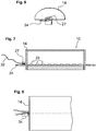
- Am Schraubklemmblock 27 können, wie in
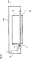
Fig. 7, 8 dargestellt, Anschlußkabel 52 zur elektrischen Kontaktierung angeschlossen werden. Wie weiter inFig. 6-8 dargestellt, weist die Abschlußplatte 14 eine Anschlußzunge 34 zum mechanischen Anschluß der Lampe 10 auf. Die Anschlußzunge 34 ist als aus der Stirnseite der Lampe 10 hervorstehende flache Metall-Lasche mit einem Fixierungsloch ausgebildet. Wie inFig. 22 dargestellt, kann die Lampe 10 in einer Leuchte 100 wechselbar aufgenommen werden, indem ein elektrisches Steuer- und Betriebsgerät 102 mit dem Anschlußblock 27 verbunden wird und die Anschlußzungen 34 an beiden Stirnseiten mit entsprechenden Aufnahmen an einem Leuchtengehäuse 104 verbunden werden, bspw. durch eine Schraubverbindung. Auf diese Weise ist die Lampe 10 an der Leuchte 100 mechanisch angebracht und elektrisch kontaktiert, so daß vom Steuer- und Betriebsgerät 102, das an eine Netzspannungsversorgung angeschlossen ist, eine für den Betrieb der Lampe 10 geeignete Spannung geliefert wird und die Lampe 10 auf diese Weise angesteuert werden kann. - In
Fig. 9a, 9b ist eine zweite und inFig. 10a, 10b eine dritte Ausführungsform einer Abschlußplatte dargestellt. Bei der zweiten Ausführungsform gemäßFig. 9a, 9b ist die Anschlußzunge 34 ebenfalls waagerecht in Längsrichtung der Lampe ausgebildet, allerdings an der Rückseite des Reflektors. In der dritten Ausführungsform ist die Anschlußzunge 34 senkrecht, parallel zur Abschlußplatte vorgesehen. - Wie in
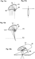
Fig. 11a, 11b (aus Symmetriegründen nur für eine Hälfte des Reflektors) gezeigt, strahlt die LED 24 auf den Reflektor 12 Licht ab. Der gesamte Lichtstrom wird von der Reflektorwandung 13 reflektiert. An der Reflektorwandung 13 wird das Licht in die Hauptabstrahlrichtung der Lampe 10 reflektiert, d. h. in Gegenrichtung der Abstrahlung der LED 24. Der sehr nah am Scheitel des Reflektors einfallende Lichtstrom wird hierbei auf die LED 24 und ihre Platine 26 zurückreflektiert, so daß es in diesem Bereich zu einer gewissen Verschattung kommt. Durch die schmale Form der Platine 26 bleibt der gesamte Verschattungseffekt jedoch relativ gering. Später wird im Rahmen vonFig. 20a, 20b eine Möglichkeit diskutiert, wie die Verschattung weiter verringert wird. - Bei der in
Fig. 11a, 11b gezeigten Variante ist die Reflektorwandung 13 von parabolischer Form. Die LED 24 ist im Brennpunkt angeordnet, so daß von dort ausgesendetes Licht im wesentlichen parallel reflektiert wird und durch die Abschlußscheibe 18 im wesentlichen parallel hindurch tritt. Das Ergebnis ist wie inFig. 11b gezeigt, in der A-Ebene eine sehr enge Lichtverteilungskurve mit maximaler Lichtstärke. - In der Variante gemäß
Fig. 12a ist die Form der Reflektorfläche 13 eine Ellipsenform mit zwei Brennpunktebenen F1 und F2. In der oberen Brennpunktebene F1 sind die LED-Elemente 24 angeordnet. Das von dort ausgesendete Licht wird in der im Abstand vor dem Lichtaustrittsbereich 16 angeordneten zweiten Brennpunktebene F2 gebündelt. - Dies läßt sich wie in
Fig. 12b dargestellt ausnutzen, um den gesamten Lichtstrom der Lampe 10 mit elliptischem Reflektor durch eine schmale schlitzförmige Öffnung 36 hindurch abzustrahlen. Eine derartige schlitzförmige Öffnung 36 kann bspw. an einer Leuchte vorgesehen sein, so daß die Leuchte - bis auf den Schlitz 36 - fast vollständig geschlossen ist. - Bei der Ausführungsform einer Lampe gemäß der Teildarstellung in
Fig. 13 ist zur Kontrolle bzw. Festlegung des Lichtausstrahlungswinkels in Lampenlängsrichtung (B-Ebene) vorgesehen, daß am Austrittsbereich 16 des Reflektors 12 Lamellen 40 angeordnet sind. Die Lamellen 40 sind im gezeigten Beispiel als flache Blenden ausgebildet, die parallel zur Abstrahlrichtung des Reflektors 12 angeordnet sind. Sie weisen in Lichtabstrahlrichtung eine gewisse Höhe auf, mit der der Ausstrahlungswinkel in Längsrichtung definiert wird. - In einer alternativen Ausgestaltung gemäß
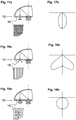
Fig. 14-16 sind an der Platine 26 zwischen den einzelnen LED-Elementen 24 Lamellen 42 angeordnet. Auch diese Lamellen dienen zur Beschränkung der Breite der Lichtverteilung in Längsrichtung. Je nach Höhe kann die Verteilung beliebig schmal eingestellt werden. Die Lamellen 42 können opak sein. Besonders bevorzugt ist eine reflektierende Oberfläche der Lamellen 42, insbesondere in Verbindung mit einer gebogenen Querschnittsform der Lamellen 42 wie inFig. 16 dargestellt. Da die Lamellen 42 zwischen den LED-Elementen 24 angeordnet sind, kann trotz der damit verbundenen Begrenzung der Breite der Abstrahlung eine fast vollständige Ausnutzung des abgestrahlten Lichts erzielt werden. - Die Abstrahlcharakteristik einer Lampe wie vorstehend beschrieben, läßt sich - neben der beschriebenen Variation der Form des Reflektors 12 - auch durch die Anordnung entsprechender optischer Elemente im Bereich der Lichtaustrittsebene 16 beeinflussen. Hier können transmittierende optische Elemente eingebracht werden, um eine gewünschte Lichtverteilung - Bündelung, Aufweitung, Streuung etc. - zu erreichen. Die optischen Elemente können als separate Einheit vorgesehen sein, besonders bevorzugt sind sie aber im Lampenabschluß 18 selbst vorgesehen. So kann die Oberfläche der Abschlußscheibe 18 gemäß einem ersten Ausführungsbeispiel (
Fig. 17a, 17b ) eine Struktur mit runden Erhebungen aufweisen. Wie die Lichtverteilungskurve zeigt, wird hierdurch die Ausstrahlung breiter als bei der reinen Verwendung eines Parabol-Reflektors. - Ein weiterer optischer Effekt kann durch den Einsatz einer Prismenstruktur gemäß der zweiten Ausführungsform (
Fig. 18a, 18b ) erzielt werden. Die prismatische Struktur der Abschlußscheibe 18 führt zu einer Ablenkung der senkrecht einfallenden Strahlen zu beiden Seiten, so daß die inFig. 18b gezeigte relativ breite Lichtverteilungskurve entsteht. - Schließlich kann, wie bei der dritten Ausführungsform (
Fig. 19a, 19b ) angedeutet, die Abschlußscheibe 18 das Licht auch diffus streuen, so daß eine diffuse Lichtverteilungskurve (Fig. 19b ) entsteht. - In
Fig. 20a, 20b ist eine mögliche Maßnahme beschrieben, mit der eine Abschattung des durch den Reflektor 12 reflektierten Lichts an der Platine 26 verringert werden kann. Der Bereich der Reflektorfläche 13, der für eine solche abgeschattete Reflektion maßgeblich ist, ist im gezeigten Beispiel der mittlere Bereich 15. Um die Abschattung zu vermeiden, ist daher die Reflektorfläche 13, die im übrigen Bereich wie zuvor beschrieben, bspw. parabolisch geformt ist, an dieser Stelle anders beschaffen. Wie in der Vergrößerung vonFig. 20b deutlich wird, ist eine Evolventen-Form mit einer mittleren Spitze 19 gebildet. Hierdurch werden Strahlen, die von der LED 24 ausgehen, nicht mehr wie bei einer Parabel-Form im wesentlichen senkrecht, d. h. ohne Winkeländerung zurückgestrahlt, sondern sie werden von den Seitenflanken der Erhöhung 19 zur Seite reflektiert und treffen somit nicht mehr die Platine 26. - Während in der vorstehenden Beschreibung stets symmetrische Reflektorquerschnitte diskutiert wurden, zeigt die Ausführungsform von
Fig. 21a, 21b eine Alternative, bei der der Reflektor 12 lediglich eine Querschnittsfläche aufweist, die im wesentlichen der Halbierung einer symmetrischen Reflektorform entspricht (natürlich auch hier, je nach gewünschten Eigenschaften, bspw. mit parabelförmigem oder sogar freiflächigem Verlauf der Reflektoroberfläche 13). Seitlich ist der abgeschlossene Reflektorraum durch eine ebene Spiegelfläche 46 abgeschlossen. WieFig. 21b zeigt, ist die entsprechende Lichtstärkeverteilung unsymmetrisch. Der gesamte Lichtstrom der LED-Lichtquelle tritt hierbei durch einen angenähert nur halb so großen Lampenabschluß aus wie bei den zuvor beschriebenen Ausführungen.
Claims (15)
- Lampeneinheit mit- einem Reflektor (12) mit einer Reflektorwandung,- und einer linearförmigen Lichtquelleneinheit (30) mit mindestens einer LED-Lichtquelle (24), die im Austrittsbereich (16) im Abstand vor der Reflektorwandung so angeordnet ist, daß sie Licht in Richtung der Reflektorwandung abstrahlt,- wobei der Austrittsbereich (16) durch einen transmittierenden Abschluß (18) verschlossen ist, so daß ein geschlossener Reflektorraum gebildet ist,- wobei der Reflektor (12), der Abschluß (18) und die Lichtquelleneinheit (26) unlösbar miteinander verbunden sind,- und wobei an der Lichtquelleneinheit (30) ein Kühlkörper (20) vorgesehen ist, der vom Austrittsbereich (16) vorsteht,- dadurch gekennzeichnet, dass außen an der Einheit (10) an einer Stirnseite des Reflektors (12) ein lösbarer elektrischer Anschluß (27) als Steckanschluß, Klemmanschluß oder Schraubanschluß zur Zuführung elektrischer Leistung zur Lichtquelleneinheit (30) vorgesehen ist, und- die Berandung der Reflektorwandung den Austrittsbereich festlegt.
- Einheit nach Anspruch 1, bei der- die Lichtquelleneinheit (30) eine Mehrzahl von LED-Lichtquellen (24) aufweist,- wobei die LED-Lichtquellen (24) auf einem gemeinsamen Träger (26) mit Leitern zur elektrischen Versorgung hintereinander in Längsrichtung angeordnet sind.
- Einheit nach einem der vorangehenden Ansprüche, bei der- ein lösbarer mechanischer Anschluß (34) der Einheit (10) zur Anbringung an einer Leuchte (100) vorgesehen ist,- wobei der mechanische Anschluß eine vorstehende Abschlußzunge (34) umfaßt,- und an mindestens einer Stirnseite des Reflektors (12) eine Abschlußplatte (14) mit dem mechanischen Anschluß (34) und einem elektrischen Anschluß (26) vorgesehen ist.
- Einheit nach einem der vorangehenden Ansprüche, bei der- eine Anzahl von quer zur Längsrichtung der Lichtquelleneinheit (30) angeordneten Lamellen (40,42) vorgesehen ist,- wobei die Lamellen (40) am Austrittsbereich (16) angeordnet sind.
- Einheit nach einem der vorangehenden Ansprüche, bei der- eine Anzahl von quer zur Längsrichtung der Lichtquelleneinheit (30) angeordneten Lamellen (40,42) vorgesehen ist,- wobei die Lamellen (42) an der Lichtquelleneinheit (30) zwischen den Lichtquellen (24) angeordnet sind.
- Einheit nach einem der vorangehenden Ansprüche, bei der- am Austrittsbereich (16) mindestens ein flaches, transparentes optisches Element zur Ablenkung von durch den Reflektor (12) reflektiertem Licht vorgesehen ist,- wobei das optische Element (18) eine strukturierte Oberfläche aufweist, die das Licht so ablenkt, daß der Abstrahlwinkel des Lichts vergrößert wird.
- Einheit nach Anspruch 6, bei der- das optische Element einen in Längsrichtung konstanten Querschnitt aufweist.
- Einheit nach einem der vorangehenden Ansprüche, bei der- das Licht der Lichtquelleneinheit (30) in einer Brennpunktachse (F2) im Abstand vom Austrittsbereich (16) gebündelt wird.
- Einheit nach einem der vorangehenden Ansprüche, bei der- der Kühlkörper mindestens eine Kavität zur Aufnahme ein'es Kühlmediums aufweist,- und der Kühlkörper an mindestens einer Stirnseite einen Anschluß für das Kühlmedium aufweist.
- Einheit nach einem der vorangehenden Ansprüche, bei der- der Abschluß (18) einen in Längsrichtung verlaufenden Spalt (21) freiläßt, in dem der als Profil ausgebildete Kühlkörper (20) angeordnet ist.
- Einheit nach einem der vorangehenden Ansprüche, bei der- der Reflektor (12) in einem Teilbereich (15) eine Querschnittsform mit einer mittleren Erhebung (19) aufweist, so daß von der Lichtquelleneinheit (30) einfallendes Licht an dem Teilbereich in eine Richtung an der Lichtquelleneinheit (30) vorbei reflektiert wird,- wobei der Teilbereich (15) eine Evolventen-Form aufweist.
- Einheit nach einem der vorangehenden Ansprüche, bei der- der Austrittsbereich (16) eine Länge von 5-100 Cm, bevorzugt 10-60 cm und eine Breite von 2,5 - 20 cm, bevorzugt 5-10 cm, aufweist.
- Leuchtensystem mit- einer Leuchte (100) mit einem Gehäuse und einem elektrischen Anschluß,- und einer Aufnahme, in der eine Lampeneinheit (10) nach einem der vorhergehenden Ansprüche wechselbar aufgenommen ist, wobei die Aufnahme einen mechanischen Anschluß umfaßt, der mit einem mechanischen Anschluß der Lampeneinheit (34) verbunden ist,- und eine elektrische Kontaktierung, die mit einer elektrischen Kontaktierung (26) der Lampeneinheit (10) verbunden ist.
- System nach Anspruch 13, bei dem- die Leuchte (100) ein elektrisches Betriebs- und/oder Steuergerät (102) zur Lieferung einer für den Betrieb der LED-Lichtquelleneinheit (30) geeigneten Spannung bzw. eines geeigneten Stroms an der elektrischen Kontaktierung (26) aufweist.
- System nach Anspruch 13 oder 14, bei dem- die Leuchte (10) einen schlitzförmigen Lichtaustrittsbereich aufweist,- und die Lampe (10) so ausgebildet ist, daß das Licht der Lichtquelleneinheit (26) in eine Brennpunktachse (F2) im Abstand von Austrittsbereich (16) gebündelt wird,- wobei die Brennpunktachse (F2) am schlitzförmigen Lichtaustrittbereich der Leuchte (100) angeordnet ist.
Applications Claiming Priority (2)
| Application Number | Priority Date | Filing Date | Title |
|---|---|---|---|
| DE102007030186A DE102007030186B4 (de) | 2007-06-27 | 2007-06-27 | Lineare LED-Lampe und Leuchtensystem mit derselben |
| PCT/EP2008/005225 WO2009000536A1 (de) | 2007-06-27 | 2008-06-26 | Lineare led-lampe |
Publications (2)
| Publication Number | Publication Date |
|---|---|
| EP2171350A1 EP2171350A1 (de) | 2010-04-07 |
| EP2171350B1 true EP2171350B1 (de) | 2018-08-15 |
Family
ID=39876796
Family Applications (1)
| Application Number | Title | Priority Date | Filing Date |
|---|---|---|---|
| EP08773700.3A Not-in-force EP2171350B1 (de) | 2007-06-27 | 2008-06-26 | Lineare led-lampe |
Country Status (3)
| Country | Link |
|---|---|
| EP (1) | EP2171350B1 (de) |
| DE (2) | DE102007030186B4 (de) |
| WO (1) | WO2009000536A1 (de) |
Families Citing this family (62)
| Publication number | Priority date | Publication date | Assignee | Title |
|---|---|---|---|---|
| DE102008031987A1 (de) * | 2008-07-07 | 2010-04-15 | Osram Gesellschaft mit beschränkter Haftung | Leuchtvorrichtung |
| DE102009006167A1 (de) | 2009-01-26 | 2010-07-29 | Ledon Lighting Jennersdorf Gmbh | Längliches Leuchten-Element und damit beleuchtetes Paneel |
| US7922364B2 (en) | 2009-03-10 | 2011-04-12 | Osram Sylvania, Inc. | LED lamp assembly |
| CN101936469B (zh) * | 2009-06-29 | 2014-10-22 | Lg伊诺特有限公司 | 照明装置 |
| WO2011001329A1 (en) * | 2009-06-29 | 2011-01-06 | Koninklijke Philips Electronics N.V. | Led luminaire using louvers as a heat sink |
| FR2949533B1 (fr) * | 2009-08-28 | 2012-08-24 | Olivier Pinon | Mobilier d'eclairage electrique |
| DE202009012555U1 (de) | 2009-09-17 | 2010-03-04 | Kunstwadl, Hans | Kühlvorrichtung |
| TWM372443U (en) * | 2009-09-21 | 2010-01-11 | Si Power Tech Co Ltd | LED lighting |
| JP2013511811A (ja) | 2009-11-18 | 2013-04-04 | ランバス・インターナショナル・リミテッド | Led用の内部集光反射器光学部品 |
| DE102009054994B4 (de) * | 2009-12-18 | 2012-06-28 | Osram Ag | Endstück für Retrofit-Leuchtstofflampe und Retrofit-Leuchtstofflampe |
| DE202010004087U1 (de) | 2010-03-24 | 2010-06-10 | Iventum Gmbh | Leuchte |
| DE202010007032U1 (de) * | 2010-04-09 | 2011-08-09 | Tridonic Jennersdorf Gmbh | LED-Modul für Strahler |
| IT1402274B1 (it) * | 2010-07-30 | 2013-08-28 | Beghelli Spa | Sistema ottico per la diffusione omogenea della luce emessa da sorgenti luminose |
| US10883702B2 (en) | 2010-08-31 | 2021-01-05 | Ideal Industries Lighting Llc | Troffer-style fixture |
| DE102010041473A1 (de) * | 2010-09-27 | 2012-03-29 | Zumtobel Lighting Gmbh | Leuchtmodulanordnung mit einer LED auf einer Platine |
| DE102010041469A1 (de) * | 2010-09-27 | 2012-03-29 | Zumtobel Lighting Gmbh | LED-Leuchte mit auswechselbarer Lichtquelle |
| DE102010061988A1 (de) * | 2010-11-25 | 2012-05-31 | Osram Ag | Lineare Beleuchtungsvorrichtung mit LEDs |
| US10309627B2 (en) | 2012-11-08 | 2019-06-04 | Cree, Inc. | Light fixture retrofit kit with integrated light bar |
| US9494293B2 (en) | 2010-12-06 | 2016-11-15 | Cree, Inc. | Troffer-style optical assembly |
| US9822951B2 (en) | 2010-12-06 | 2017-11-21 | Cree, Inc. | LED retrofit lens for fluorescent tube |
| US9581312B2 (en) | 2010-12-06 | 2017-02-28 | Cree, Inc. | LED light fixtures having elongated prismatic lenses |
| KR101325142B1 (ko) * | 2011-05-20 | 2013-11-20 | 주식회사 케이엠더블유 | 임의배광이 가능한 엘이디 조명장치 |
| JP4979827B1 (ja) * | 2011-05-23 | 2012-07-18 | ポスコ エルイーディ カンパニー リミテッド | 光半導体基盤管型照明装置 |
| DE102011051034A1 (de) | 2011-06-14 | 2012-12-20 | Selux Aktiengesellschaft | LED Beleuchtungsanordnung |
| US10823347B2 (en) * | 2011-07-24 | 2020-11-03 | Ideal Industries Lighting Llc | Modular indirect suspended/ceiling mount fixture |
| US8752976B2 (en) * | 2011-07-24 | 2014-06-17 | Cree, Inc. | Light fixture with co-formed plenum component |
| US9423117B2 (en) | 2011-12-30 | 2016-08-23 | Cree, Inc. | LED fixture with heat pipe |
| US10544925B2 (en) | 2012-01-06 | 2020-01-28 | Ideal Industries Lighting Llc | Mounting system for retrofit light installation into existing light fixtures |
| US9777897B2 (en) | 2012-02-07 | 2017-10-03 | Cree, Inc. | Multiple panel troffer-style fixture |
| US8905575B2 (en) | 2012-02-09 | 2014-12-09 | Cree, Inc. | Troffer-style lighting fixture with specular reflector |
| US9310038B2 (en) | 2012-03-23 | 2016-04-12 | Cree, Inc. | LED fixture with integrated driver circuitry |
| US9494294B2 (en) | 2012-03-23 | 2016-11-15 | Cree, Inc. | Modular indirect troffer |
| FR2988299A1 (fr) * | 2012-03-23 | 2013-09-27 | Claranor | Dispositif de decontamination par lumiere ultra-violette et utilisation associee |
| US10054274B2 (en) | 2012-03-23 | 2018-08-21 | Cree, Inc. | Direct attach ceiling-mounted solid state downlights |
| US9360185B2 (en) | 2012-04-09 | 2016-06-07 | Cree, Inc. | Variable beam angle directional lighting fixture assembly |
| US9874322B2 (en) | 2012-04-10 | 2018-01-23 | Cree, Inc. | Lensed troffer-style light fixture |
| US9285099B2 (en) | 2012-04-23 | 2016-03-15 | Cree, Inc. | Parabolic troffer-style light fixture |
| EP2667087B1 (de) * | 2012-05-24 | 2014-10-15 | Goodrich Lighting Systems GmbH | Raumschiff-Bodenmanöverlicht |
| US8931929B2 (en) | 2012-07-09 | 2015-01-13 | Cree, Inc. | Light emitting diode primary optic for beam shaping |
| US9746173B2 (en) | 2012-09-13 | 2017-08-29 | Quarkstar Llc | Illumination devices including enclosure panels with luminaire modules |
| US9494304B2 (en) | 2012-11-08 | 2016-11-15 | Cree, Inc. | Recessed light fixture retrofit kit |
| US9441818B2 (en) | 2012-11-08 | 2016-09-13 | Cree, Inc. | Uplight with suspended fixture |
| US9482396B2 (en) | 2012-11-08 | 2016-11-01 | Cree, Inc. | Integrated linear light engine |
| AT513588A1 (de) * | 2012-11-14 | 2014-05-15 | Ernst Mag Helldorff | Leuchtmodul |
| US10648643B2 (en) | 2013-03-14 | 2020-05-12 | Ideal Industries Lighting Llc | Door frame troffer |
| US9423104B2 (en) | 2013-03-14 | 2016-08-23 | Cree, Inc. | Linear solid state lighting fixture with asymmetric light distribution |
| US9052075B2 (en) | 2013-03-15 | 2015-06-09 | Cree, Inc. | Standardized troffer fixture |
| DE202013101792U1 (de) * | 2013-04-25 | 2014-07-29 | Zumtobel Lighting Gmbh | Leuchte mit optischem System zur Lichtabgabe über eine längliche Lichtaustrittsöffnung |
| CN103453358A (zh) * | 2013-07-15 | 2013-12-18 | 深圳市巧精灵照明有限公司 | 一种发光二极管筒灯 |
| USD786471S1 (en) | 2013-09-06 | 2017-05-09 | Cree, Inc. | Troffer-style light fixture |
| US9291340B2 (en) | 2013-10-23 | 2016-03-22 | Rambus Delaware Llc | Lighting assembly having n-fold rotational symmetry |
| AT514917B1 (de) | 2013-11-22 | 2015-05-15 | Neulicht Lighting Solutions Gmbh | LED-Leuchte |
| JP6747807B2 (ja) * | 2014-01-30 | 2020-08-26 | 興和株式会社 | 照明装置 |
| USD807556S1 (en) | 2014-02-02 | 2018-01-09 | Cree Hong Kong Limited | Troffer-style fixture |
| USD772465S1 (en) | 2014-02-02 | 2016-11-22 | Cree Hong Kong Limited | Troffer-style fixture |
| US10451253B2 (en) | 2014-02-02 | 2019-10-22 | Ideal Industries Lighting Llc | Troffer-style fixture with LED strips |
| USD749768S1 (en) | 2014-02-06 | 2016-02-16 | Cree, Inc. | Troffer-style light fixture with sensors |
| US10527225B2 (en) | 2014-03-25 | 2020-01-07 | Ideal Industries, Llc | Frame and lens upgrade kits for lighting fixtures |
| CN104566259B (zh) * | 2014-12-19 | 2018-01-30 | 东莞市闻誉实业有限公司 | Led条形灯 |
| US10012354B2 (en) | 2015-06-26 | 2018-07-03 | Cree, Inc. | Adjustable retrofit LED troffer |
| CN114777681B (zh) * | 2017-10-06 | 2025-03-04 | 维西公司 | 使用多个阴影投掷器扫描仪确定基准器的准确位置的方法 |
| DE102019004708A1 (de) | 2019-07-04 | 2020-01-23 | Daimler Ag | Fahrzeug mit einer Leuchte |
Citations (2)
| Publication number | Priority date | Publication date | Assignee | Title |
|---|---|---|---|---|
| WO2005055328A1 (ja) * | 2003-12-05 | 2005-06-16 | Mitsubishi Denki Kabushiki Kaisha | 発光装置及びこれを用いた照明器具 |
| WO2006086967A1 (de) * | 2005-02-18 | 2006-08-24 | Patent-Treuhand-Gesellschaft für elektrische Glühlampen mbH | Farbadaptives beleuchtungssystem |
Family Cites Families (18)
| Publication number | Priority date | Publication date | Assignee | Title |
|---|---|---|---|---|
| DE20002565U1 (de) * | 2000-02-14 | 2001-06-28 | Zumtobel Staff Ges.M.B.H., Dornbirn | Leuchtdiodenanordnung mit Reflektor |
| JP4560936B2 (ja) * | 2000-10-11 | 2010-10-13 | 豊田合成株式会社 | 光源装置及びその製造方法 |
| DE20007134U1 (de) * | 2000-04-18 | 2000-08-17 | OSRAM Opto Semiconductors GmbH & Co. oHG, 93049 Regensburg | Leuchte mit einstellbarem Farbort |
| DE10105622A1 (de) * | 2001-02-08 | 2002-08-14 | Insta Elektro Gmbh | Beleuchtungseinrichtung |
| FI110636B (fi) * | 2001-06-29 | 2003-02-28 | Teknoware Oy | Järjestely valaisimen yhteydessä ja valaisin |
| FR2831647B1 (fr) | 2001-10-26 | 2004-04-16 | Peugeot Citroen Automobiles Sa | Feu de signalisation de vehicule automobile pour diffusion de faisceaux lumineux indirects |
| JP4027688B2 (ja) * | 2002-03-15 | 2007-12-26 | 株式会社小糸製作所 | 車両用灯具 |
| US7011431B2 (en) * | 2002-04-23 | 2006-03-14 | Nichia Corporation | Lighting apparatus |
| US6871993B2 (en) * | 2002-07-01 | 2005-03-29 | Accu-Sort Systems, Inc. | Integrating LED illumination system for machine vision systems |
| US6851835B2 (en) * | 2002-12-17 | 2005-02-08 | Whelen Engineering Company, Inc. | Large area shallow-depth full-fill LED light assembly |
| US6924973B2 (en) * | 2003-04-03 | 2005-08-02 | Atto Display Co., Ltd. | Light emitting diode assembly for an illuminated sign |
| US6976769B2 (en) * | 2003-06-11 | 2005-12-20 | Cool Options, Inc. | Light-emitting diode reflector assembly having a heat pipe |
| DE10345567A1 (de) * | 2003-09-29 | 2005-05-19 | Erco Leuchten Gmbh | Reflektorleuchte, wie Boden-, Decken- oder Wandeinbau-Reflektorleuchte, insbesondere Stufen-Reflektorleuchte |
| JP4778503B2 (ja) | 2004-03-05 | 2011-09-21 | オスラム ゲゼルシャフト ミット ベシュレンクテル ハフツング | ランプ |
| US7315048B2 (en) * | 2004-10-22 | 2008-01-01 | Avago Technologies Ecbu Ip (Singapore) Pte Ltd | Method and apparatus for mixing light emitted by a plurality of solid-state light emitters |
| JP2006179572A (ja) * | 2004-12-21 | 2006-07-06 | Sharp Corp | 発光ダイオード、バックライト装置および発光ダイオードの製造方法 |
| EP1948995B1 (de) * | 2005-11-11 | 2010-04-28 | Koninklijke Philips Electronics N.V. | Leuchte mit led |
| DE202007006815U1 (de) * | 2007-05-11 | 2007-07-19 | Carl Croon Gmbh | Bauelement |
-
2007
- 2007-06-27 DE DE102007030186A patent/DE102007030186B4/de not_active Expired - Fee Related
-
2008
- 2008-06-26 WO PCT/EP2008/005225 patent/WO2009000536A1/de not_active Ceased
- 2008-06-26 EP EP08773700.3A patent/EP2171350B1/de not_active Not-in-force
- 2008-06-26 DE DE112008001660T patent/DE112008001660A5/de not_active Ceased
Patent Citations (2)
| Publication number | Priority date | Publication date | Assignee | Title |
|---|---|---|---|---|
| WO2005055328A1 (ja) * | 2003-12-05 | 2005-06-16 | Mitsubishi Denki Kabushiki Kaisha | 発光装置及びこれを用いた照明器具 |
| WO2006086967A1 (de) * | 2005-02-18 | 2006-08-24 | Patent-Treuhand-Gesellschaft für elektrische Glühlampen mbH | Farbadaptives beleuchtungssystem |
Also Published As
| Publication number | Publication date |
|---|---|
| DE102007030186A1 (de) | 2009-01-02 |
| DE112008001660A5 (de) | 2010-10-28 |
| DE102007030186B4 (de) | 2009-04-23 |
| WO2009000536A1 (de) | 2008-12-31 |
| EP2171350A1 (de) | 2010-04-07 |
Similar Documents
| Publication | Publication Date | Title |
|---|---|---|
| DE102007030186B4 (de) | Lineare LED-Lampe und Leuchtensystem mit derselben | |
| EP2049835B1 (de) | Leuchte | |
| EP2404110B1 (de) | Beleuchtungsvorrichtung mit mindestens einem kühlkörper | |
| EP2748514B1 (de) | Leuchteneinheit für eine leuchte, sowie leuchte | |
| EP2207996A1 (de) | Led-lampe mit diffusor | |
| EP2020562A1 (de) | Wandleuchte | |
| DE19755658A1 (de) | Leuchte mit einem scheibenförmigen Lichtleiter | |
| EP2478286A1 (de) | Led-leuchtenelement zur beleuchtung eines lichtkastens mit homogener lichtverteilung | |
| EP2023035A1 (de) | Leuchte | |
| EP2622259B1 (de) | Leuchtmodulanordnung mit einer led auf einer platine | |
| EP2236912A2 (de) | Leuchte | |
| WO2012032191A1 (de) | Led-beleuchtungsvorrichtung | |
| DE102018123968B4 (de) | Beleuchtungsvorrichtung mit einer Light-Engine aus einem Streifen | |
| DE10001412A1 (de) | Beleuchtungseinheit | |
| EP3748223B1 (de) | Anordnung zur lichtabgabe | |
| EP2494271B1 (de) | Leuchte zum ausleuchten eines zielbereiches mittels rückwärtsreflexion von licht eines leuchtdiodenmoduls an einem reflektor | |
| EP1813857A1 (de) | Lichtquelle | |
| EP3607247A1 (de) | Leuchte | |
| DE102005024830B4 (de) | Leuchtdioden-Anordnung | |
| WO2013127557A1 (de) | Lampe | |
| EP3446031B1 (de) | Schaltschrankleuchte mit verstellbarer leuchtmittelplatine | |
| DE102010001204B4 (de) | Längliches Leuchten-Element und damit beleuchtetes Panel | |
| DE10211620B4 (de) | Leuchtmittelmodul mit integriertem Leuchtmittel | |
| DE102010004177A1 (de) | LED-Straßenbeleuchtung | |
| EP2910843B1 (de) | Beleuchtungseinheit |
Legal Events
| Date | Code | Title | Description |
|---|---|---|---|
| PUAI | Public reference made under article 153(3) epc to a published international application that has entered the european phase |
Free format text: ORIGINAL CODE: 0009012 |
|
| 17P | Request for examination filed |
Effective date: 20100125 |
|
| AK | Designated contracting states |
Kind code of ref document: A1 Designated state(s): AT BE BG CH CY CZ DE DK EE ES FI FR GB GR HR HU IE IS IT LI LT LU LV MC MT NL NO PL PT RO SE SI SK TR |
|
| AX | Request for extension of the european patent |
Extension state: AL BA MK RS |
|
| DAX | Request for extension of the european patent (deleted) | ||
| RAP1 | Party data changed (applicant data changed or rights of an application transferred) |
Owner name: SITECO BELEUCHTUNGSTECHNIK GMBH |
|
| RIN1 | Information on inventor provided before grant (corrected) |
Inventor name: SITECO BELEUCHTUNGSTECHNIK GMBH |
|
| RAP1 | Party data changed (applicant data changed or rights of an application transferred) |
Owner name: SITECO BELEUCHTUNGSTECHNIK GMBH |
|
| RIN1 | Information on inventor provided before grant (corrected) |
Inventor name: SITECO BELEUCHTUNGSTECHNIK GMBH |
|
| STAA | Information on the status of an ep patent application or granted ep patent |
Free format text: STATUS: EXAMINATION IS IN PROGRESS |
|
| 17Q | First examination report despatched |
Effective date: 20161031 |
|
| GRAP | Despatch of communication of intention to grant a patent |
Free format text: ORIGINAL CODE: EPIDOSNIGR1 |
|
| STAA | Information on the status of an ep patent application or granted ep patent |
Free format text: STATUS: GRANT OF PATENT IS INTENDED |
|
| RIC1 | Information provided on ipc code assigned before grant |
Ipc: F21S 8/00 20060101ALI20180319BHEP Ipc: F21V 13/04 20060101AFI20180319BHEP |
|
| INTG | Intention to grant announced |
Effective date: 20180418 |
|
| GRAS | Grant fee paid |
Free format text: ORIGINAL CODE: EPIDOSNIGR3 |
|
| GRAA | (expected) grant |
Free format text: ORIGINAL CODE: 0009210 |
|
| STAA | Information on the status of an ep patent application or granted ep patent |
Free format text: STATUS: THE PATENT HAS BEEN GRANTED |
|
| AK | Designated contracting states |
Kind code of ref document: B1 Designated state(s): AT BE BG CH CY CZ DE DK EE ES FI FR GB GR HR HU IE IS IT LI LT LU LV MC MT NL NO PL PT RO SE SI SK TR |
|
| REG | Reference to a national code |
Ref country code: CH Ref legal event code: EP Ref country code: GB Ref legal event code: FG4D Free format text: NOT ENGLISH Ref country code: AT Ref legal event code: REF Ref document number: 1030214 Country of ref document: AT Kind code of ref document: T Effective date: 20180815 |
|
| RIN1 | Information on inventor provided before grant (corrected) |
Inventor name: HOFMANN, HARALD |
|
| REG | Reference to a national code |
Ref country code: IE Ref legal event code: FG4D Free format text: LANGUAGE OF EP DOCUMENT: GERMAN |
|
| REG | Reference to a national code |
Ref country code: DE Ref legal event code: R096 Ref document number: 502008016262 Country of ref document: DE |
|
| REG | Reference to a national code |
Ref country code: NL Ref legal event code: MP Effective date: 20180815 |
|
| REG | Reference to a national code |
Ref country code: LT Ref legal event code: MG4D |
|
| PG25 | Lapsed in a contracting state [announced via postgrant information from national office to epo] |
Ref country code: FI Free format text: LAPSE BECAUSE OF FAILURE TO SUBMIT A TRANSLATION OF THE DESCRIPTION OR TO PAY THE FEE WITHIN THE PRESCRIBED TIME-LIMIT Effective date: 20180815 Ref country code: LT Free format text: LAPSE BECAUSE OF FAILURE TO SUBMIT A TRANSLATION OF THE DESCRIPTION OR TO PAY THE FEE WITHIN THE PRESCRIBED TIME-LIMIT Effective date: 20180815 Ref country code: SE Free format text: LAPSE BECAUSE OF FAILURE TO SUBMIT A TRANSLATION OF THE DESCRIPTION OR TO PAY THE FEE WITHIN THE PRESCRIBED TIME-LIMIT Effective date: 20180815 Ref country code: GR Free format text: LAPSE BECAUSE OF FAILURE TO SUBMIT A TRANSLATION OF THE DESCRIPTION OR TO PAY THE FEE WITHIN THE PRESCRIBED TIME-LIMIT Effective date: 20181116 Ref country code: NO Free format text: LAPSE BECAUSE OF FAILURE TO SUBMIT A TRANSLATION OF THE DESCRIPTION OR TO PAY THE FEE WITHIN THE PRESCRIBED TIME-LIMIT Effective date: 20181115 Ref country code: BG Free format text: LAPSE BECAUSE OF FAILURE TO SUBMIT A TRANSLATION OF THE DESCRIPTION OR TO PAY THE FEE WITHIN THE PRESCRIBED TIME-LIMIT Effective date: 20181115 Ref country code: IS Free format text: LAPSE BECAUSE OF FAILURE TO SUBMIT A TRANSLATION OF THE DESCRIPTION OR TO PAY THE FEE WITHIN THE PRESCRIBED TIME-LIMIT Effective date: 20181215 Ref country code: NL Free format text: LAPSE BECAUSE OF FAILURE TO SUBMIT A TRANSLATION OF THE DESCRIPTION OR TO PAY THE FEE WITHIN THE PRESCRIBED TIME-LIMIT Effective date: 20180815 |
|
| PG25 | Lapsed in a contracting state [announced via postgrant information from national office to epo] |
Ref country code: HR Free format text: LAPSE BECAUSE OF FAILURE TO SUBMIT A TRANSLATION OF THE DESCRIPTION OR TO PAY THE FEE WITHIN THE PRESCRIBED TIME-LIMIT Effective date: 20180815 Ref country code: ES Free format text: LAPSE BECAUSE OF FAILURE TO SUBMIT A TRANSLATION OF THE DESCRIPTION OR TO PAY THE FEE WITHIN THE PRESCRIBED TIME-LIMIT Effective date: 20180815 Ref country code: LV Free format text: LAPSE BECAUSE OF FAILURE TO SUBMIT A TRANSLATION OF THE DESCRIPTION OR TO PAY THE FEE WITHIN THE PRESCRIBED TIME-LIMIT Effective date: 20180815 |
|
| PG25 | Lapsed in a contracting state [announced via postgrant information from national office to epo] |
Ref country code: IT Free format text: LAPSE BECAUSE OF FAILURE TO SUBMIT A TRANSLATION OF THE DESCRIPTION OR TO PAY THE FEE WITHIN THE PRESCRIBED TIME-LIMIT Effective date: 20180815 Ref country code: RO Free format text: LAPSE BECAUSE OF FAILURE TO SUBMIT A TRANSLATION OF THE DESCRIPTION OR TO PAY THE FEE WITHIN THE PRESCRIBED TIME-LIMIT Effective date: 20180815 Ref country code: CZ Free format text: LAPSE BECAUSE OF FAILURE TO SUBMIT A TRANSLATION OF THE DESCRIPTION OR TO PAY THE FEE WITHIN THE PRESCRIBED TIME-LIMIT Effective date: 20180815 Ref country code: EE Free format text: LAPSE BECAUSE OF FAILURE TO SUBMIT A TRANSLATION OF THE DESCRIPTION OR TO PAY THE FEE WITHIN THE PRESCRIBED TIME-LIMIT Effective date: 20180815 Ref country code: PL Free format text: LAPSE BECAUSE OF FAILURE TO SUBMIT A TRANSLATION OF THE DESCRIPTION OR TO PAY THE FEE WITHIN THE PRESCRIBED TIME-LIMIT Effective date: 20180815 |
|
| REG | Reference to a national code |
Ref country code: DE Ref legal event code: R097 Ref document number: 502008016262 Country of ref document: DE |
|
| PG25 | Lapsed in a contracting state [announced via postgrant information from national office to epo] |
Ref country code: DK Free format text: LAPSE BECAUSE OF FAILURE TO SUBMIT A TRANSLATION OF THE DESCRIPTION OR TO PAY THE FEE WITHIN THE PRESCRIBED TIME-LIMIT Effective date: 20180815 Ref country code: SK Free format text: LAPSE BECAUSE OF FAILURE TO SUBMIT A TRANSLATION OF THE DESCRIPTION OR TO PAY THE FEE WITHIN THE PRESCRIBED TIME-LIMIT Effective date: 20180815 |
|
| PLBE | No opposition filed within time limit |
Free format text: ORIGINAL CODE: 0009261 |
|
| STAA | Information on the status of an ep patent application or granted ep patent |
Free format text: STATUS: NO OPPOSITION FILED WITHIN TIME LIMIT |
|
| 26N | No opposition filed |
Effective date: 20190516 |
|
| PG25 | Lapsed in a contracting state [announced via postgrant information from national office to epo] |
Ref country code: SI Free format text: LAPSE BECAUSE OF FAILURE TO SUBMIT A TRANSLATION OF THE DESCRIPTION OR TO PAY THE FEE WITHIN THE PRESCRIBED TIME-LIMIT Effective date: 20180815 |
|
| PG25 | Lapsed in a contracting state [announced via postgrant information from national office to epo] |
Ref country code: MC Free format text: LAPSE BECAUSE OF FAILURE TO SUBMIT A TRANSLATION OF THE DESCRIPTION OR TO PAY THE FEE WITHIN THE PRESCRIBED TIME-LIMIT Effective date: 20180815 |
|
| REG | Reference to a national code |
Ref country code: CH Ref legal event code: PL |
|
| GBPC | Gb: european patent ceased through non-payment of renewal fee |
Effective date: 20190626 |
|
| REG | Reference to a national code |
Ref country code: BE Ref legal event code: MM Effective date: 20190630 |
|
| PG25 | Lapsed in a contracting state [announced via postgrant information from national office to epo] |
Ref country code: TR Free format text: LAPSE BECAUSE OF FAILURE TO SUBMIT A TRANSLATION OF THE DESCRIPTION OR TO PAY THE FEE WITHIN THE PRESCRIBED TIME-LIMIT Effective date: 20180815 |
|
| PG25 | Lapsed in a contracting state [announced via postgrant information from national office to epo] |
Ref country code: IE Free format text: LAPSE BECAUSE OF NON-PAYMENT OF DUE FEES Effective date: 20190626 Ref country code: GB Free format text: LAPSE BECAUSE OF NON-PAYMENT OF DUE FEES Effective date: 20190626 |
|
| REG | Reference to a national code |
Ref country code: DE Ref legal event code: R081 Ref document number: 502008016262 Country of ref document: DE Owner name: SITECO GMBH, DE Free format text: FORMER OWNER: SITECO BELEUCHTUNGSTECHNIK GMBH & CO KG, 83301 TRAUNREUT, DE Ref country code: DE Ref legal event code: R082 Ref document number: 502008016262 Country of ref document: DE Representative=s name: BOEHMERT & BOEHMERT ANWALTSPARTNERSCHAFT MBB -, DE |
|
| PG25 | Lapsed in a contracting state [announced via postgrant information from national office to epo] |
Ref country code: LI Free format text: LAPSE BECAUSE OF NON-PAYMENT OF DUE FEES Effective date: 20190630 Ref country code: CH Free format text: LAPSE BECAUSE OF NON-PAYMENT OF DUE FEES Effective date: 20190630 Ref country code: LU Free format text: LAPSE BECAUSE OF NON-PAYMENT OF DUE FEES Effective date: 20190626 Ref country code: BE Free format text: LAPSE BECAUSE OF NON-PAYMENT OF DUE FEES Effective date: 20190630 |
|
| PG25 | Lapsed in a contracting state [announced via postgrant information from national office to epo] |
Ref country code: FR Free format text: LAPSE BECAUSE OF NON-PAYMENT OF DUE FEES Effective date: 20190630 Ref country code: PT Free format text: LAPSE BECAUSE OF FAILURE TO SUBMIT A TRANSLATION OF THE DESCRIPTION OR TO PAY THE FEE WITHIN THE PRESCRIBED TIME-LIMIT Effective date: 20181215 |
|
| REG | Reference to a national code |
Ref country code: AT Ref legal event code: PC Ref document number: 1030214 Country of ref document: AT Kind code of ref document: T Owner name: SITECO GMBH, DE Effective date: 20201028 |
|
| PG25 | Lapsed in a contracting state [announced via postgrant information from national office to epo] |
Ref country code: CY Free format text: LAPSE BECAUSE OF FAILURE TO SUBMIT A TRANSLATION OF THE DESCRIPTION OR TO PAY THE FEE WITHIN THE PRESCRIBED TIME-LIMIT Effective date: 20180815 |
|
| PG25 | Lapsed in a contracting state [announced via postgrant information from national office to epo] |
Ref country code: HU Free format text: LAPSE BECAUSE OF FAILURE TO SUBMIT A TRANSLATION OF THE DESCRIPTION OR TO PAY THE FEE WITHIN THE PRESCRIBED TIME-LIMIT; INVALID AB INITIO Effective date: 20080626 Ref country code: MT Free format text: LAPSE BECAUSE OF FAILURE TO SUBMIT A TRANSLATION OF THE DESCRIPTION OR TO PAY THE FEE WITHIN THE PRESCRIBED TIME-LIMIT Effective date: 20180815 |
|
| PGFP | Annual fee paid to national office [announced via postgrant information from national office to epo] |
Ref country code: DE Payment date: 20220621 Year of fee payment: 15 |
|
| PGFP | Annual fee paid to national office [announced via postgrant information from national office to epo] |
Ref country code: AT Payment date: 20220617 Year of fee payment: 15 |
|
| REG | Reference to a national code |
Ref country code: DE Ref legal event code: R119 Ref document number: 502008016262 Country of ref document: DE |
|
| REG | Reference to a national code |
Ref country code: AT Ref legal event code: MM01 Ref document number: 1030214 Country of ref document: AT Kind code of ref document: T Effective date: 20230626 |
|
| PG25 | Lapsed in a contracting state [announced via postgrant information from national office to epo] |
Ref country code: AT Free format text: LAPSE BECAUSE OF NON-PAYMENT OF DUE FEES Effective date: 20230626 |
|
| PG25 | Lapsed in a contracting state [announced via postgrant information from national office to epo] |
Ref country code: DE Free format text: LAPSE BECAUSE OF NON-PAYMENT OF DUE FEES Effective date: 20240103 Ref country code: AT Free format text: LAPSE BECAUSE OF NON-PAYMENT OF DUE FEES Effective date: 20230626 |