EP2494271B1 - Leuchte zum ausleuchten eines zielbereiches mittels rückwärtsreflexion von licht eines leuchtdiodenmoduls an einem reflektor - Google Patents
Leuchte zum ausleuchten eines zielbereiches mittels rückwärtsreflexion von licht eines leuchtdiodenmoduls an einem reflektor Download PDFInfo
- Publication number
- EP2494271B1 EP2494271B1 EP10784297.3A EP10784297A EP2494271B1 EP 2494271 B1 EP2494271 B1 EP 2494271B1 EP 10784297 A EP10784297 A EP 10784297A EP 2494271 B1 EP2494271 B1 EP 2494271B1
- Authority
- EP
- European Patent Office
- Prior art keywords
- light
- emitting diode
- coolant
- diode module
- reflector
- Prior art date
- Legal status (The legal status is an assumption and is not a legal conclusion. Google has not performed a legal analysis and makes no representation as to the accuracy of the status listed.)
- Not-in-force
Links
- 239000002826 coolant Substances 0.000 claims description 73
- 230000005855 radiation Effects 0.000 claims description 22
- 238000001816 cooling Methods 0.000 claims description 16
- 230000003287 optical effect Effects 0.000 claims description 14
- 239000007788 liquid Substances 0.000 claims description 4
- 238000000576 coating method Methods 0.000 claims description 3
- 239000007787 solid Substances 0.000 claims description 3
- 239000004020 conductor Substances 0.000 claims description 2
- 239000011521 glass Substances 0.000 description 3
- 230000015572 biosynthetic process Effects 0.000 description 2
- 238000000265 homogenisation Methods 0.000 description 2
- 238000005286 illumination Methods 0.000 description 2
- 239000000463 material Substances 0.000 description 2
- 229920003023 plastic Polymers 0.000 description 2
- XLYOFNOQVPJJNP-UHFFFAOYSA-N water Substances O XLYOFNOQVPJJNP-UHFFFAOYSA-N 0.000 description 2
- RYGMFSIKBFXOCR-UHFFFAOYSA-N Copper Chemical compound [Cu] RYGMFSIKBFXOCR-UHFFFAOYSA-N 0.000 description 1
- 238000003491 array Methods 0.000 description 1
- 230000005540 biological transmission Effects 0.000 description 1
- 239000011248 coating agent Substances 0.000 description 1
- 229910052802 copper Inorganic materials 0.000 description 1
- 239000010949 copper Substances 0.000 description 1
- 230000007423 decrease Effects 0.000 description 1
- 230000006735 deficit Effects 0.000 description 1
- 230000001419 dependent effect Effects 0.000 description 1
- 229910052736 halogen Inorganic materials 0.000 description 1
- 150000002367 halogens Chemical class 0.000 description 1
- 238000010438 heat treatment Methods 0.000 description 1
- 239000004033 plastic Substances 0.000 description 1
- 239000012780 transparent material Substances 0.000 description 1
Images

Classifications
-
- F—MECHANICAL ENGINEERING; LIGHTING; HEATING; WEAPONS; BLASTING
- F21—LIGHTING
- F21V—FUNCTIONAL FEATURES OR DETAILS OF LIGHTING DEVICES OR SYSTEMS THEREOF; STRUCTURAL COMBINATIONS OF LIGHTING DEVICES WITH OTHER ARTICLES, NOT OTHERWISE PROVIDED FOR
- F21V5/00—Refractors for light sources
- F21V5/008—Combination of two or more successive refractors along an optical axis
-
- F—MECHANICAL ENGINEERING; LIGHTING; HEATING; WEAPONS; BLASTING
- F21—LIGHTING
- F21V—FUNCTIONAL FEATURES OR DETAILS OF LIGHTING DEVICES OR SYSTEMS THEREOF; STRUCTURAL COMBINATIONS OF LIGHTING DEVICES WITH OTHER ARTICLES, NOT OTHERWISE PROVIDED FOR
- F21V13/00—Producing particular characteristics or distribution of the light emitted by means of a combination of elements specified in two or more of main groups F21V1/00 - F21V11/00
- F21V13/02—Combinations of only two kinds of elements
- F21V13/04—Combinations of only two kinds of elements the elements being reflectors and refractors
-
- F—MECHANICAL ENGINEERING; LIGHTING; HEATING; WEAPONS; BLASTING
- F21—LIGHTING
- F21V—FUNCTIONAL FEATURES OR DETAILS OF LIGHTING DEVICES OR SYSTEMS THEREOF; STRUCTURAL COMBINATIONS OF LIGHTING DEVICES WITH OTHER ARTICLES, NOT OTHERWISE PROVIDED FOR
- F21V29/00—Protecting lighting devices from thermal damage; Cooling or heating arrangements specially adapted for lighting devices or systems
- F21V29/50—Cooling arrangements
- F21V29/56—Cooling arrangements using liquid coolants
-
- F—MECHANICAL ENGINEERING; LIGHTING; HEATING; WEAPONS; BLASTING
- F21—LIGHTING
- F21V—FUNCTIONAL FEATURES OR DETAILS OF LIGHTING DEVICES OR SYSTEMS THEREOF; STRUCTURAL COMBINATIONS OF LIGHTING DEVICES WITH OTHER ARTICLES, NOT OTHERWISE PROVIDED FOR
- F21V5/00—Refractors for light sources
- F21V5/04—Refractors for light sources of lens shape
- F21V5/045—Refractors for light sources of lens shape the lens having discontinuous faces, e.g. Fresnel lenses
-
- F—MECHANICAL ENGINEERING; LIGHTING; HEATING; WEAPONS; BLASTING
- F21—LIGHTING
- F21V—FUNCTIONAL FEATURES OR DETAILS OF LIGHTING DEVICES OR SYSTEMS THEREOF; STRUCTURAL COMBINATIONS OF LIGHTING DEVICES WITH OTHER ARTICLES, NOT OTHERWISE PROVIDED FOR
- F21V7/00—Reflectors for light sources
- F21V7/0008—Reflectors for light sources providing for indirect lighting
-
- G—PHYSICS
- G02—OPTICS
- G02B—OPTICAL ELEMENTS, SYSTEMS OR APPARATUS
- G02B19/00—Condensers, e.g. light collectors or similar non-imaging optics
- G02B19/0004—Condensers, e.g. light collectors or similar non-imaging optics characterised by the optical means employed
- G02B19/0019—Condensers, e.g. light collectors or similar non-imaging optics characterised by the optical means employed having reflective surfaces only (e.g. louvre systems, systems with multiple planar reflectors)
- G02B19/0023—Condensers, e.g. light collectors or similar non-imaging optics characterised by the optical means employed having reflective surfaces only (e.g. louvre systems, systems with multiple planar reflectors) at least one surface having optical power
-
- G—PHYSICS
- G02—OPTICS
- G02B—OPTICAL ELEMENTS, SYSTEMS OR APPARATUS
- G02B19/00—Condensers, e.g. light collectors or similar non-imaging optics
- G02B19/0033—Condensers, e.g. light collectors or similar non-imaging optics characterised by the use
- G02B19/0047—Condensers, e.g. light collectors or similar non-imaging optics characterised by the use for use with a light source
- G02B19/0061—Condensers, e.g. light collectors or similar non-imaging optics characterised by the use for use with a light source the light source comprising a LED
-
- F—MECHANICAL ENGINEERING; LIGHTING; HEATING; WEAPONS; BLASTING
- F21—LIGHTING
- F21V—FUNCTIONAL FEATURES OR DETAILS OF LIGHTING DEVICES OR SYSTEMS THEREOF; STRUCTURAL COMBINATIONS OF LIGHTING DEVICES WITH OTHER ARTICLES, NOT OTHERWISE PROVIDED FOR
- F21V29/00—Protecting lighting devices from thermal damage; Cooling or heating arrangements specially adapted for lighting devices or systems
- F21V29/50—Cooling arrangements
- F21V29/56—Cooling arrangements using liquid coolants
- F21V29/58—Cooling arrangements using liquid coolants characterised by the coolants
-
- F—MECHANICAL ENGINEERING; LIGHTING; HEATING; WEAPONS; BLASTING
- F21—LIGHTING
- F21Y—INDEXING SCHEME ASSOCIATED WITH SUBCLASSES F21K, F21L, F21S and F21V, RELATING TO THE FORM OR THE KIND OF THE LIGHT SOURCES OR OF THE COLOUR OF THE LIGHT EMITTED
- F21Y2115/00—Light-generating elements of semiconductor light sources
- F21Y2115/10—Light-emitting diodes [LED]
Definitions
- the invention relates to a luminaire for illuminating a target area by means of back reflection on a reflector with a light emitting diode module having at least one light emitting diode (LED), and a cooling device for the light emitting diode module, wherein the cooling means for the light of the light emitting diode module transparent liquid as a coolant and a transparent coolant tank for Inclusion of the coolant includes.
- a light emitting diode module having at least one light emitting diode (LED), and a cooling device for the light emitting diode module, wherein the cooling means for the light of the light emitting diode module transparent liquid as a coolant and a transparent coolant tank for Inclusion of the coolant includes.
- An illumination system using such a luminaire is known from US 2007/0253733 A1 known. This document describes the use of the illumination system for a fluorescence microscope.
- An LED light source is positioned at a focal point of an elliptical mirror and emits its radiation into a half space facing the mirror. The mirror reflects the incident radiation back and focuses it on a subsequent optical system. Due to the back reflection on the reflector, ie reflection of rays with an angle of incidence of less than 45 °, it is unavoidable that the LED light source and the mechanical structures necessary for its support stand in the way of the reflected light itself.
- the object of the present invention is to provide a generic lamp, in which a high efficiency of light transmission and the cooling of the LED module is made possible, with the emergence of artifacts, such as shadowing should be minimized.
- the present invention is based on the recognition that a liquid cooling of an LED module can be designed so that the light emitted by the LED and reflected by the reflector light is influenced in a defined manner when it hits the coolant tank.
- the coolant container comprises a first and a second transparent wall, between which the coolant is located and which extend substantially perpendicular to the optical axis of the reflector and have a surface such that in an assembled state, in which the LED module with the Reflector is coupled, almost the entire, that is, at least 90% of the reflector of the reflected radiation of the light emitting diode module, which passes into the target area, passes through the coolant tank.
- the coolant container therefore has two walls parallel to one another and covers the entire cross section of the radiation emanating from the light-emitting diode module and reflected by the reflector.
- the walls of the coolant tank may be made of glass or plastic.
- the coolant can be, for example, water whose refractive index of 1.33 differs only slightly from that of low-refraction glasses or transparent plastics (about 1.5), or transparent oil.
- the first and the second wall of the coolant tank may be rectangular, in particular square, its or its outline may be adapted to the outline of the reflector. It is advantageous if the outer edge of the coolant container is outside the range in which the radiation emanating from the lamp is reflected in order to preclude an impairment of the reflected radiation. Then it does not matter if the border itself is transparent or not. Ideally, all the radiation of the light-emitting diode module which is reflected by the reflector and reaches the target area passes through the coolant container.
- the LED module is formed so that the at least one light emitting diode emits at most in a half space.
- the LED module can be arranged so that the entire emitted light impinges on the reflector and is reflected by it in the direction of the target area, so that the light reaching the target area has a defined characteristic.
- the cooling device also serves as a holder for the light-emitting diode module.
- the light-emitting diode module comprises a heat-conducting element which is coupled to the light-emitting diode and which is embedded in the coolant container such that it is in contact with the coolant.
- the LED module is attached to the cooling device and at the same time is a ensures effective dissipation of heat generated during operation.
- a particularly efficient heat transfer from the heat-conducting element to the coolant can be achieved, for example, by forming the heat-conducting element as a solid cylinder with fins projecting therefrom or having holes through which the coolant flows.
- the heat-conducting element may have a rough or structured surface.
- the light-emitting diode module comprises a printed circuit board, on the upper side of which one or more light-emitting diodes are mounted and whose underside is connected in particular by means of a thermally conductive material to the heat-conducting element, wherein the dimension of the heat-conducting in a direction perpendicular to the optical axis of the light emitting diode module is less than or equal to the corresponding dimension of the printed circuit board. In this way, only the shading on the LED module reduces the amount of light reaching the target area.
- the first wall that is to say the wall facing the reflector in the installed state, of the coolant container has conductive coatings for electrical contacting of the light-emitting diode module, which can be made transparent.
- the first and the second wall of the coolant tank are formed as plane-parallel plates. In this way, the radiation passing through the coolant container is influenced as little as possible.
- the outside of the first and / or the second wall of the coolant container is designed to realize a specific optical function curved.
- the coolant container at the same time assume the function of an optical element, for example a lens, whereby additional components and thus costs can be saved.
- a two-dimensional lens array is formed on the outside of the first and / or the second wall of the coolant container.
- the coolant container may have the shape of a honeycomb condenser, whereby a homogenization of the radiation passing through it is effected.
- a first embodiment of a lamp according to the invention is shown.
- the luminaire comprises an LED module 12 which is combined with a reflector 30 such that the light emitted by the LED or LEDs 14 is reflected by the reflector 30 in the reverse direction, and a cooling device 10 for cooling the LED module simultaneously serves as a holder for the LED module 12.
- the LED module 12 comprises one or more LEDs 14 and a heat-conducting element 16 represented by a semicircle.
- An LED module 12 can also have a plurality of LEDs 14 instead of one.
- the LED or LEDs 14 are located on a printed circuit board, on the underside of the heat-conducting element 16 is arranged.
- the heat-conducting element 16 is a copper block. Its contour is adapted to the shape of the circuit board, wherein its size in a direction perpendicular to the optical axis of the LED module is less than or equal to the corresponding size of the circuit board. In this way the loss of light due to shading is reduced to a minimum.
- the heat-conducting element 16 is designed as a solid cylinder and has fins or ribs projecting therefrom in order to be able to deliver the heat absorbed during operation particularly well to the cooling device 10.
- the cooling device comprises a throughflowed coolant container 20 having a first wall 22 and a second wall 24, between which a coolant 26 is located.
- the heat-conducting element 16 is through a corresponding opening in the first wall 22 is inserted into the coolant tank 20 so that it is in contact with the coolant 26 and that the LED module 12 is thereby anchored to the coolant tank 20.
- a transparent conductive coating is formed on the outside of the first wall 22, which is connected to the printed circuit board of the LED module 12.
- the electrical contact can also be done with thin wires. How out Fig.
- the coolant tank 20 at the top and at the bottom of leads 27, 28, through which the coolant 26 can flow into and out of the coolant tank 20.
- the coolant 26 flows through the upper supply line 27 into the coolant reservoir 20 and out of the coolant reservoir 20 through the lower supply line 28, so that coolant flows around the heat-conducting element 16.
- the coolant container is closed after filling with coolant, and no active circulation of coolant takes place during operation.
- a transparent liquid is used as the coolant 26, a transparent liquid is used. This may be water whose refractive index of 1.33 does not differ greatly from the refractive index of transparent materials suitable for the walls of the coolant container 20, such as glass with a refractive index of 1.41.
- the walls 22 and 24 of the coolant tank 20 are aligned parallel to each other and perpendicular to the optical axis 36 of the LED module 12. Its area is larger than that of the reflected beam from the reflector 30.
- Fig. 1 are shown to illustrate the beam path, the two edges of the radiation emitted by the LED module 12 radiation.
- the walls 22 and 24 are rectangular or adapted to the reflector 30 from its outline. At their edges they are connected by suitable means, in particular by side walls. These edge regions are preferably located outside the region of the reflected radiation in order to avoid disturbances of the reflected radiation.
- the insides of the walls of the coolant tank 20 are planar to prevent vortex formation of the coolant 26 on the walls as it flows through.
- the outer sides in particular of the first wall 22 and the second wall 24 of the coolant tank 20 are flat, so that it is at the two walls 22 and 24 are plane-parallel plates. In this way, the entire coolant container 20 acts on the incident radiation as a plane-parallel plate.
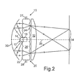
- Fig. 2 a second embodiment of the lamp according to the invention is shown.
- the embodiment according to Fig. 2 is characterized by the fact that the coolant container 20 in addition to the function of the cooling and the holder of the LED module 12 still assumes an optical function. Otherwise, the cooling device 10 according to the second embodiment corresponds to that in connection with the first embodiment according to FIG Fig. 1 given description.
- the in Fig. 2 shown coolant container 20 is formed as a honeycomb condenser.
- 20 lens arrays are formed on the outer sides of the first wall 22 and the second wall 24 of the coolant tank. This causes homogenization of the radiation passing through the coolant container 20.
- a Fresnel lens 32 is still provided after the coolant container 20 for bundling the radiation onto the target region 34.
- the coolant reservoir 20 is arranged in the luminaire such that the LED module 12, whose LED or LEDs emit at most into a half-space, is located in the vicinity of the focal point of the reflector.
- the reflector 30 collects the complete LED radiation and can send it through the coolant reservoir.
- conic sections such as paraboloids or ellipsoids are used. The use of a reflector in backward reflection thus causes a good utilization of the radiation with a simple structure.
- the lamp according to the invention can be designed so that it can be installed in existing lamps with a reflector, so that a retrofit of previous halogen lamp solutions is possible.
- Preferred applications for the solution according to the invention are medical lights, small-etendue applications such as projectors, or high-beam intensity applications such as headlamps. It is particularly efficient and inexpensive if a large diameter of the optics is necessary.
Landscapes
- Engineering & Computer Science (AREA)
- General Engineering & Computer Science (AREA)
- Physics & Mathematics (AREA)
- General Physics & Mathematics (AREA)
- Optics & Photonics (AREA)
- Arrangement Of Elements, Cooling, Sealing, Or The Like Of Lighting Devices (AREA)
- Non-Portable Lighting Devices Or Systems Thereof (AREA)
Description
- Die Erfindung betrifft eine Leuchte zum Ausleuchten eines Zielbereiches mittels Rückwärtsreflexion an einem Reflektor mit einem Leuchtdiodenmodul mit wenigstens einer Leuchtdiode (LED), sowie einer Kühleinrichtung für das Leuchtdiodenmodul, wobei die Kühleinrichtung eine für das Licht des Leuchtdiodenmoduls transparente Flüssigkeit als Kühlmittel und einen transparenten Kühlmittelbehälter zur Aufnahme des Kühlmittels umfasst.
- Ein Beleuchtungssystem, das eine derartige Leuchte nutzt, ist aus der
US 2007/0253733 A1 bekannt. Dieses Dokument beschreibt die Verwendung des Beleuchtungssystems für ein Fluoreszenzmikroskop. Eine LED-Lichtquelle ist in einem Brennpunkt eines elliptischen Spiegels positioniert und emittiert ihre Strahlung in einen dem Spiegel zugewandten Halbraum. Der Spiegel reflektiert die auftreffende Strahlung zurück und fokussiert sie auf ein nachfolgendes optisches System. Aufgrund der Rückwärtsreflexion am Reflektor, d.h. Reflexion von Strahlen mit einem Einfallswinkel von unter 45°, lässt es sich nicht vermeiden, dass die LED-Lichtquelle und die zur ihrer Halterung notwendigen mechanischen Aufbauten dem reflektierten Licht selbst im Wege stehen. - Weil die Lichtausbeute einer LED mit steigender Temperatur abnimmt, muss eine Abführung der bei ihrem Betrieb entstehenden Wärme gewährleistet werden, um das Aufheizen der LED während des Betriebs zu minimieren. Bei der Anordnung eines LED-Moduls im Brennpunkt eines rückwärts reflektierenden Reflektors kann dieses nicht durch einen sonst üblichen Kühlkörper entwärmt werden, weil dieser einen noch größeren Teil des am Reflektor reflektierten Lichts abschatten würde. Statt dessen muss die Wärme durch die Halterungen nach außen geführt werden. Auch wenn diese sehr kompakt ausgelegt sein können, um Verluste des reflektierten Lichts möglichst gering zu halten, nehmen sie mehr Raum ein als eine LED alleine und führen daher zu einer Abschattung des reflektierten Lichts. Selbst wenn man die Halterungen transparent gestaltet, wird die darauf auftreffende reflektierte Strahlung beeinflusst und die optische Effizienz der Anordnung verringert.
- Die Aufgabe der vorliegenden Erfindung ist es, eine gattungsgemäße Leuchte bereitzustellen, bei der eine hohe Effizienz der Lichtübertragung und der Entwärmung des LED-Moduls ermöglicht wird, wobei die Entstehung von Artefakten, wie Abschattungen, minimiert sein soll.
- Diese Aufgabe wird gelöst durch eine Leuchte mit den Merkmalen von Anspruch 1.
- Besonders vorteilhafte Ausgestaltungen finden sich in den abhängigen Ansprüchen.
- Der vorliegenden Erfindung liegt die Erkenntnis zugrunde, dass eine Flüssigkühlung eines LED-Moduls so gestaltet werden kann, dass das von der LED emittierte und von dem Reflektor reflektierte Licht in definierter Weise beeinflusst wird, wenn es auf den Kühlmittelbehälter auftrifft. Dazu umfasst der Kühlmittelbehälter eine erste und eine zweite transparente Wand, zwischen denen sich das Kühlmittel befindet und die sich im Wesentlichen senkrecht zur optischen Achse des Reflektors erstrecken und eine solche Fläche besitzen, dass in einem montierten Zustand, in dem das LED-Modul mit dem Reflektor gekoppelt ist, nahezu die gesamte, das heißt mindestens 90 % der an dem Reflektor reflektierten Strahlung des Leuchtdiodenmoduls, die in den Zielbereich gelangt, durch den Kühlmittelbehälter hindurchtritt.
- Der Kühlmittelbehälter weist also zwei zueinander parallele Wände auf und deckt den gesamten Querschnitt der vom Leuchtdiodenmodul ausgehenden und vom Reflektor reflektierten Strahlung ab. Die Wände des Kühlmittelbehälters können aus Glas oder aus Kunststoff sein. Bei dem Kühlmittel kann es sich beispielsweise um Wasser handeln, dessen Brechungsindex von 1.33 sich nur wenig von dem niedrigbrechender Gläser oder transparenter Kunststoffe (etwa 1.5) unterscheidet, oder um transparentes Öl. Bei der Auswahl des Kühlmittels und des Materials für den Kühlmittelbehälter ist es jedenfalls vorteilhaft, wenn der Brechungsindex der ersten und der zweiten Wand und der des Kühlmittels so ähnlich sind, dass die Reflexionsverluste an den Grenzflächen zwischen den Wänden und dem Kühlmittel sehr klein sind. Die erste und die zweite Wand des Kühlmittelbehälters können rechteckig, insbesondere quadratisch, sein oder ihr Umriss kann an den Umriss des Reflektors angepasst sein. Es ist dabei von Vorteil, wenn der äußere Rand des Kühlmittelbehälters außerhalb des Bereichs liegt, in den die von der Leuchte ausgehende Strahlung reflektiert wird, um eine Beeinträchtigung der reflektierten Strahlung auszuschließen. Dann spielt es auch keine Rolle, ob der Rand selbst transparent ist oder nicht. Im Idealfall tritt sämtliche an dem Reflektor reflektierte Strahlung des Leuchtdiodenmoduls, die in den Zielbereich gelangt, durch den Kühlmittelbehälter hindurch.
- Vorzugsweise ist das LED-Modul so ausgebildet, dass die mindestens eine Leuchtdiode höchstens in einen Halbraum ausstrahlt. Auf diese Weise kann das LED-Modul so angeordnet werden, dass das gesamte ausgestrahlte Licht auf dem Reflektor auftrifft und von diesem in Richtung des Zielbereiches reflektiert wird, so dass das in den Zielbereich gelangende Licht eine definierte Charakteristik hat.
- Gemäß einer bevorzugten Ausgestaltung der Erfindung dient die Kühleinrichtung außerdem als Halterung für das Leuchtdiodenmodul. Dadurch werden zwei Funktionen in einem Bauteil vereint, wobei eine Abschattung durch eine zusätzliche Halterung vermieden wird
- Gemäß einer besonders bevorzugten Ausgestaltung der Erfindung umfasst das Leuchtdiodenmodul ein mit der Leuchtdiode gekoppeltes Wärmeleitelement, das so in den Kühlmittelbehälter eingelassen ist, dass es mit dem Kühlmittel in Kontakt steht. Auf diese Weise ist das LED-Modul an der Kühleinrichtung befestigt und gleichzeitig ist eine effektive Ableitung der im Betrieb entstehenden Wärme gewährleistet. Ein besonders effizienter Wärmeübergang von dem Wärmeleitelement auf das Kühlmittel lässt sich beispielsweise dadurch erreichen, dass das Wärmeleitelement als massiver Zylinder mit davon abstehenden Finnen ausgebildet ist oder Löcher aufweist, die vom Kühlmittel durchströmt werden. Des weiteren kann das Wärmeleitelement eine raue oder strukturierte Oberfläche aufweisen.
- Gemäß einer weiteren besonders bevorzugten Ausgestaltung der Erfindung umfasst das Leuchtdiodenmodul eine Leiterplatte, auf deren Oberseite eine oder mehrere Leuchtdioden montiert sind und deren Unterseite insbesondere mittels eines thermisch leitenden Materials mit dem Wärmeleitelement verbunden ist, wobei die Abmessung des Wärmeleitelements in einer Richtung senkrecht zur optischen Achse des Leuchtdiodenmoduls kleiner oder gleich der entsprechenden Abmessung der Leiterplatte ist. Auf diese Weise reduziert lediglich die Abschattung am LED-Modul die Menge des in den Zielbereich gelangenden Lichts.
- Gemäß einer weiteren bevorzugten Ausgestaltung der Erfindung weist die erste Wand, das heißt die im montierten Zustand dem Reflektor zugewandte Wand, des Kühlmittelbehälters leitfähige Beschichtungen zur elektrischen Kontaktierung des Leuchtdiodenmoduls auf, welche transparent ausgeführt sein können.
- Gemäß einer weiteren bevorzugten Ausgestaltung der Erfindung sind die erste und die zweite Wand des Kühlmittelbehälters als planparallele Platten ausgebildet. Auf diese Weise wird die durch den Kühlmittelbehälter hindurchgehende Strahlung möglichst wenig beeinflusst.
- Gemäß einer weiteren bevorzugten Ausgestaltung der Erfindung ist die Außenseite der ersten und/oder der zweiten Wand des Kühlmittelbehälters zum Verwirklichen einer speziellen optischen Funktion gekrümmt ausgebildet. Dadurch kann der Kühlmittelbehälter gleichzeitig die Funktion eines optischen Elements, beispielsweise einer Linse, übernehmen, wodurch zusätzliche Bauteile und damit Kosten gespart werden können.
- Besonders bevorzugt ist auf der Außenseite der ersten und/oder der zweiten Wand des Kühlmittelbehälters ein zweidimensionales Linsenarray ausgebildet. Insbesondere kann der Kühlmittelbehälter die Gestalt eines Wabenkondensors aufweisen, wodurch eine Homogenisierung der durch ihn hindurchgehenden Strahlung bewirkt wird.
- Im Folgenden soll die Erfindung anhand von Ausführungsbeispielen näher erläutert werden. Die Figuren zeigen:
- Fig. 1
- eine schematische Schnittansicht eines ersten Ausführungsbeispiels der erfindungsgemäßen Leuchte; und
- Fig. 2
- eine schematische Schnittansicht eines zweiten Ausführungsbeispiels der erfindungsgemäßen Leuchte.
- In den Figuren sind einander entsprechende Bestandteile mit denselben Bezugszeichen versehen. Die dargestellten Bestandteile sowie die Größenverhältnisse der Bestandteile untereinander sind nicht als maßstabsgerecht anzusehen.
- In
Fig. 1 ist ein erstes Ausführungsbeispiel einer erfindungsgemäßen Leuchte dargestellt. Die Leuchte umfasst ein LED-Modul 12, das so mit einem Reflektor 30 kombiniert ist, dass das von der oder den LEDs 14 ausgesendete Licht von dem Reflektor 30 in Rückwärtsrichtung reflektiert wird, sowie eine Kühleinrichtung 10 zum Kühlen des LED-Moduls, die gleichzeitig als Halterung für das LED-Modul 12 dient. Das LED-Modul 12 umfasst eine oder mehrere durch einen Halbkreis dargestellte LED 14 und ein Wärmeleitelement 16. Ein LED-Modul 12 kann statt einer auch mehrere LEDs 14 aufweisen. - Die LED beziehungsweise LEDs 14 befinden sich auf einer Leiterplatte, auf deren Unterseite das Wärmeleitelement 16 angeordnet ist. Vorzugsweise handelt es sich bei dem Wärmeleitelement 16 um einen Kupferblock. Sein Umriss ist an die Form der Leiterplatte angepasst, wobei seine Größe in einer Richtung senkrecht zur optischen Achse des LED-Moduls kleiner oder gleich der entsprechenden Größe der Leiterplatte ist. Auf diese Weise wird der Lichtverlust durch Abschattung auf ein Minimum reduziert. Insbesondere ist das Wärmeleitelement 16 als massiver Zylinder ausgebildet und weist davon abstehende Finnen oder Rippen auf, um die im Betrieb aufgenommene Wärme besonders gut an die Kühleinrichtung 10 abgeben zu können.
- Die Kühleinrichtung umfasst einen durchströmten Kühlmittelbehälter 20 mit einer ersten Wand 22 und einer zweiten Wand 24, zwischen denen sich ein Kühlmittel 26 befindet. Das Wärmeleitelement 16 ist durch eine entsprechende Öffnung in der ersten Wand 22 so in den Kühlmittelbehälter 20 eingelassen, dass es mit dem Kühlmittel 26 in Kontakt ist und dass das LED-Modul 12 dadurch an dem Kühlmittelbehälter 20 verankert ist. Zur elektrischen Kontaktierung des LED-Moduls 12 ist außen auf der ersten Wand 22 eine in der Figur nicht dargestellte transparente leitfähige Beschichtung ausgebildet, die mit der Leiterplatte des LED-Moduls 12 verbunden ist. Alternativ kann die elektrische Kontaktierung aber auch mit dünnen Drähten erfolgen. Wie aus
Fig. 1 ersichtlich ist, weist der Kühlmittelbehälter 20 am oberen und am unteren Rand Zuleitungen 27, 28 auf, durch die das Kühlmittel 26 in den Kühlmittelbehälter 20 hinein und aus diesem herausströmen kann. Beispielsweise strömt das Kühlmittel 26 durch die obere Zuleitung 27 in den Kühlmittelbehälter 20 hinein und durch die untere Zuleitung 28 wieder aus dem Kühlmittelbehälter 20 aus, so dass das Wärmeleitelement 16 von Kühlmittel umströmt wird. Es wäre aber auch denkbar, dass der Kühlmittelbehälter nach dem Befüllen mit Kühlmittel verschlossen wird, und während des Betriebs keine aktive Umwälzung von Kühlmittel erfolgt. Als Kühlmittel 26 wird eine transparente Flüssigkeit verwendet. Dabei kann es sich um Wasser handeln, dessen Brechungsindex von 1,33 sich von dem Brechungsindex von für die Wände des Kühlmittelbehälters 20 infrage kommenden transparenten Materialien, wie beispielsweise Glas mit einem Brechungsindex von 1,41, nicht stark unterscheidet. Die Wände 22 und 24 des Kühlmittelbehälters 20 sind parallel zueinander und senkrecht zur optischen Achse 36 des LED-Moduls 12 ausgerichtet. Ihre Fläche ist größer als die des vom Reflektor 30 reflektierten Bündels. - In
Fig. 1 sind zur Veranschaulichung des Strahlenganges die beiden Ränder der von dem LED-Modul 12 emittierten Strahlung eingezeichnet. Die Wände 22 und 24 sind rechteckig oder von ihrem Umriss her an den Reflektor 30 angepasst. An ihren Rändern sind sie durch geeignete Mittel, insbesondere durch Seitenwände, miteinander verbunden. Diese Randbereiche befinden sich vorzugsweise außerhalb des Bereichs der reflektierten Strahlung, um Störungen der reflektierten Strahlung zu vermeiden. Die Innenseiten der Wände des Kühlmittelbehälters 20 sind eben ausgebildet, um eine Wirbelbildung des Kühlmittels 26 an den Wänden beim Hindurchströmen zu vermeiden. Gemäß dem inFig. 1 gezeigten ersten Ausführungsbeispiel der Erfindung sind auch die Außenseiten insbesondere der ersten Wand 22 und der zweiten Wand 24 des Kühlmittelbehälters 20 eben ausgebildet, so dass es sich bei den beiden Wänden 22 und 24 um planparallele Platten handelt. Auf diese Weise wirkt der gesamte Kühlmittelbehälter 20 auf die auftreffende Strahlung wie eine planparallele Platte. - In
Fig. 2 ist ein zweites Ausführungsbeispiel der erfindungsgemäßen Leuchte dargestellt. Das Ausführungsbeispiel gemäßFig. 2 zeichnet sich dadurch aus, dass der Kühlmittelbehälter 20 zusätzlich zur Funktion der Kühlung und der Halterung des LED-Moduls 12 noch eine optische Funktion übernimmt. Ansonsten entspricht die Kühleinrichtung 10 gemäß dem zweiten Ausführungsbeispiel der im Zusammenhang mit dem ersten Ausführungsbeispiel gemäßFig. 1 gegebenen Beschreibung. Der inFig. 2 gezeigte Kühlmittelbehälter 20 ist als Wabenkondensor ausgebildet. Dazu sind auf den Außenseiten der ersten Wand 22 und der zweiten Wand 24 des Kühlmittelbehälters 20 Linsenarrays ausgebildet. Dadurch wird eine Homogenisierung der durch den Kühlmittelbehälter 20 hindurchgehenden Strahlung bewirkt. In Ausbreitungsrichtung der Strahlung gesehen ist nach dem Kühlmittelbehälter 20 noch eine Fresnellinse 32 zur Bündelung der Strahlung auf den Zielbereich 34 vorgesehen. Durch die Integration der optischen Funktion eines Wabenkondensors in den Kühlmittelbehälter 20 lassen sich sowohl Platz als auch Material und dadurch Kosten sparen. In ähnlicher Weise lassen sich andere gewünschte optische Funktionen durch geeignete Ausbildung der Wände 22 und 24 des Kühlmittelbehälters 20 verwirklichen. - Bei beiden Ausführungsbeispielen ist der Kühlmittelbehälter 20 so in der Leuchte angeordnet, dass das LED-Modul 12, dessen LED oder LEDs höchstens in einen Halbraum ausstrahlt, sich in der Nähe des Brennpunktes des Reflektors befindet. Somit sammelt der Reflektor 30 die komplette LED-Strahlung ein und kann diese durch den Kühlmittelbehälter senden. Als Reflektoren werden insbesondere Kegelschnittfiguren, wie Paraboloide oder Ellipsoide verwendet. Die Nutzung eines Reflektors in Rückwärtsreflexion bewirkt somit eine gute Ausnutzung der Strahlung bei einfachem Aufbau.
- Die erfindungsgemäße Leuchte lässt sich so gestalten, dass sie in vorhandene Lampen mit einem Reflektor eingebaut werden kann, so dass ein Retrofit bisheriger Halogenlampenlösungen möglich ist. Bevorzugte Anwendungen für die erfindungsgemäße Lösung sind medizinische Leuchten, Anwendungen kleiner Etendue, wie Projektoren, oder Anwendungen hoher Achslichtstärke, wie Scheinwerfer. Sie ist besonders effizient und kostengünstig, wenn ein großer Durchmesser der Optik notwendig ist.
Claims (11)
- Leuchte zum Ausleuchten eines Zielbereiches (34) mittels Rückwärtsreflexion an einem Reflektor (30) mit- einem Leuchtdiodenmodul (12) mit wenigstens einer Leuchtdiode (14) und- einer Kühleinrichtung (10) für das Leuchtdiodenmodul (12), wobei die Kühleinrichtung eine für das Licht des Leuchtdiodenmoduls transparente Flüssigkeit (26) als Kühlmittel und einen transparenten Kühlmittelbehälter (20) zur Aufnahme des Kühlmittels (26) umfasst,
dadurch gekennzeichnet, dass
der Kühlmittelbehälter (20) eine erste (22) und eine zweite transparente Wand (24) umfasst, zwischen denen sich das Kühlmittel (26) befindet und die sich im Wesentlichen senkrecht zur optischen Achse (36) des Reflektors (30) erstrecken und eine solche Fläche besitzen, dass in einem montierten Zustand, in dem das Leuchtdiodenmodul (12) und die Kühleinrichtung (10) mit dem Reflektor (30) verbunden sind, mindestens 90 % der an dem Reflektor (30) reflektierten Strahlung des Leuchtdiodenmoduls (12), die in den Zielbereich (34) gelangt, durch den Kühlmittelbehälter (20) hindurchtritt. - Leuchte nach Anspruch 1,
dadurch gekennzeichnet, dass
die erste (22) und die zweite Wand (24) des Kühlmittelbehälters (20) eine solche Fläche besitzen, dass sämtliche an dem Reflektor (30) reflektierte Strahlung des Leuchtdiodenmoduls (12), die in den Zielbereich (34) gelangt, durch den Kühlmittelbehälter (20) hindurchtritt. - Leuchte nach Anspruch 1 oder 2,
dadurch gekennzeichnet, dass
die wenigstens eine Leuchtdiode (14) so ausgebildet ist, dass sie höchstens in einen Halbraum ausstrahlt. - Leuchte nach einem der Ansprüche 1 bis 3,
dadurch gekennzeichnet, dass
die Kühleinrichtung außerdem als Halterung für das Leuchtdiodenmodul (12) dient. - Leuchte nach Anspruch 4,
dadurch gekennzeichnet, dass
das Leuchtdiodenmodul (12) ein mit der wenigstens einen Leuchtdiode (14) gekoppeltes Wärmeleitelement (16) umfasst, das so in den Kühlmittelbehälter (20) eingelassen ist, dass es mit dem Kühlmittel (26) in Kontakt steht. - Leuchte nach Anspruch 5,
dadurch gekennzeichnet, dass
das Wärmeleitelement (16) als massiver Zylinder mit davon abstehenden Finnen ausgebildet ist. - Leuchte nach Anspruch 5 oder 6,
dadurch gekennzeichnet, dass
das Leuchtdiodenmodul (12) eine Leiterplatte umfasst, auf deren Oberseite ein oder mehrere Leuchtdioden (14) montiert sind und deren Unterseite insbesondere mittels eines thermisch leitenden Materials mit dem Wärmeleitelement (16) verbunden ist, wobei die Abmessung des Wärmeleitelements (16) in einer Richtung senkrecht zur optischen Achse des Leuchtdiodenmoduls (12) kleiner oder gleich der entsprechenden Abmessung der Leiterplatte ist. - Leuchte nach einem der vorhergehenden Ansprüche,
dadurch gekennzeichnet, dass
die erste Wand (22) des Kühlmittelbehälters (20) leitfähige Beschichtungen zur elektrischen Kontaktierung des Leuchtdiodenmoduls (12) aufweist. - Leuchte nach einem der vorhergehenden Ansprüche,
dadurch gekennzeichnet, dass
die erste (22) und die zweite Wand (24) des Kühlmittelbehälters (20) als planparallele Platten ausgebildet sind. - Leuchte nach einem der Ansprüche 1 bis 8,
dadurch gekennzeichnet, dass
die Außenseite der ersten (22) und/oder der zweiten Wand (24) des Kühlmittelbehälters (20) zum Verwirklichen einer optischen Funktion gekrümmt ausgebildet ist. - Leuchte nach Anspruch 10,
dadurch gekennzeichnet, dass
auf der Außenseite der ersten (22) und/oder der zweiten Wand (24) des Kühlmittelbehälters (20) ein zweidimensionales Linsenarray ausgebildet ist.
Applications Claiming Priority (2)
| Application Number | Priority Date | Filing Date | Title |
|---|---|---|---|
| DE102010001007A DE102010001007B4 (de) | 2010-01-19 | 2010-01-19 | Leuchte zum Ausleuchten eines Zielbereiches mittels Rückwärtsreflexion von Licht eines Leuchtdiodenmoduls an einem Reflektor |
| PCT/EP2010/068088 WO2011088922A1 (de) | 2010-01-19 | 2010-11-24 | Leuchte zum ausleuchten eines zielbereiches mittels rückwärtsreflexion von licht eines leuchtdiodenmoduls an einem reflektor |
Publications (2)
| Publication Number | Publication Date |
|---|---|
| EP2494271A1 EP2494271A1 (de) | 2012-09-05 |
| EP2494271B1 true EP2494271B1 (de) | 2014-11-19 |
Family
ID=43708836
Family Applications (1)
| Application Number | Title | Priority Date | Filing Date |
|---|---|---|---|
| EP10784297.3A Not-in-force EP2494271B1 (de) | 2010-01-19 | 2010-11-24 | Leuchte zum ausleuchten eines zielbereiches mittels rückwärtsreflexion von licht eines leuchtdiodenmoduls an einem reflektor |
Country Status (6)
| Country | Link |
|---|---|
| US (1) | US8801230B2 (de) |
| EP (1) | EP2494271B1 (de) |
| CN (1) | CN102713431B (de) |
| DE (1) | DE102010001007B4 (de) |
| DK (1) | DK2494271T5 (de) |
| WO (1) | WO2011088922A1 (de) |
Families Citing this family (6)
| Publication number | Priority date | Publication date | Assignee | Title |
|---|---|---|---|---|
| US9212805B2 (en) * | 2013-10-16 | 2015-12-15 | Disney Enterprises, Inc. | Special effects system using retroreflections to create an illusion of glowing toys and props |
| WO2016026695A1 (en) * | 2014-08-21 | 2016-02-25 | Philips Lighting Holding B.V. | Light emitting device |
| CN106287329A (zh) * | 2015-06-04 | 2017-01-04 | 国立中央大学 | 液冷式高功率led投射灯 |
| WO2019133101A2 (en) * | 2017-10-26 | 2019-07-04 | Mirada Technologies Inc. | Lidar systems and optical beam steering devices having neutrally buoyant reflectors therein |
| DE102019213150A1 (de) * | 2019-08-30 | 2021-03-04 | Würth Elektronik eiSos Gmbh & Co. KG | Strahler und Verfahren zum Abstrahlen von Licht |
| US12044507B2 (en) * | 2021-08-18 | 2024-07-23 | Raytheon Company | Component packaging for centrally obscured optical system |
Family Cites Families (10)
| Publication number | Priority date | Publication date | Assignee | Title |
|---|---|---|---|---|
| US6439888B1 (en) * | 1999-05-03 | 2002-08-27 | Pls Liquidating Llc | Optical source and method |
| US20040264192A1 (en) * | 2003-05-06 | 2004-12-30 | Seiko Epson Corporation | Light source apparatus, method of manufacture therefor, and projection-type display apparatus |
| US6976769B2 (en) * | 2003-06-11 | 2005-12-20 | Cool Options, Inc. | Light-emitting diode reflector assembly having a heat pipe |
| US7367691B2 (en) | 2003-06-16 | 2008-05-06 | Industrial Technology Research Institute | Omnidirectional one-dimensional photonic crystal and light emitting device made from the same |
| US7722211B2 (en) * | 2004-08-06 | 2010-05-25 | Koninklijke Philips Electronics N.V. | Light engine |
| NL1027627C2 (nl) | 2004-11-30 | 2006-05-31 | Ccm Beheer Bv | Verlichtingssysteem. |
| DE102005017751B4 (de) * | 2005-04-12 | 2008-07-31 | Deutsches Zentrum für Luft- und Raumfahrt e.V. | LED-Scheinwerfer |
| JP4644544B2 (ja) * | 2005-07-01 | 2011-03-02 | 大日本印刷株式会社 | 面光源装置 |
| CN101078470B (zh) * | 2006-05-26 | 2010-12-08 | 曹嘉灿 | 光源照明装置 |
| CA2753643A1 (en) * | 2009-02-27 | 2010-09-02 | Koninklijke Philips Electronics N.V. | Led-based lamps and thermal management systems therefor |
-
2010
- 2010-01-19 DE DE102010001007A patent/DE102010001007B4/de not_active Expired - Fee Related
- 2010-11-24 US US13/574,195 patent/US8801230B2/en active Active
- 2010-11-24 CN CN201080061910.0A patent/CN102713431B/zh not_active Expired - Fee Related
- 2010-11-24 DK DK10784297.3T patent/DK2494271T5/da active
- 2010-11-24 EP EP10784297.3A patent/EP2494271B1/de not_active Not-in-force
- 2010-11-24 WO PCT/EP2010/068088 patent/WO2011088922A1/de not_active Ceased
Also Published As
| Publication number | Publication date |
|---|---|
| CN102713431B (zh) | 2015-08-12 |
| DK2494271T3 (da) | 2015-01-19 |
| DE102010001007A1 (de) | 2011-07-21 |
| DE102010001007B4 (de) | 2013-01-03 |
| WO2011088922A1 (de) | 2011-07-28 |
| EP2494271A1 (de) | 2012-09-05 |
| US20120294001A1 (en) | 2012-11-22 |
| US8801230B2 (en) | 2014-08-12 |
| CN102713431A (zh) | 2012-10-03 |
| DK2494271T5 (da) | 2015-01-26 |
Similar Documents
| Publication | Publication Date | Title |
|---|---|---|
| EP2459924B1 (de) | Beleuchtungsvorrichtung mit leuchtdioden | |
| DE102007030186B4 (de) | Lineare LED-Lampe und Leuchtensystem mit derselben | |
| EP2614694B1 (de) | Beschichtungsverfahren für ein optoelektronisches chip-on-board-modul | |
| DE112013001416B4 (de) | Flächenlichtquelle | |
| EP2494271B1 (de) | Leuchte zum ausleuchten eines zielbereiches mittels rückwärtsreflexion von licht eines leuchtdiodenmoduls an einem reflektor | |
| DE102012223854A1 (de) | Remote-Phosphor-Konvertereinrichtung | |
| DE102006015377B4 (de) | Halbleiter-Strahlungsquelle sowie Lichthärtgerät | |
| WO2013010634A1 (de) | Optoelektronisches modul mit verbesserter optik | |
| WO2006012842A2 (de) | Elektromagnetische strahlung emittierendes optoelektronisches bauelement und leuchtmodul | |
| EP2332490B1 (de) | Lichthärtgerät für Dentalzwecke | |
| EP1805815A2 (de) | Beleuchtungseinrichtung, kfz-scheinwerfer und verfahren zur herstellung einer beleuctungseinrichtung | |
| WO2006045545A1 (de) | Linse und mikrolinsenarray | |
| WO2012038172A1 (de) | Leuchtvorrichtung | |
| DE102012223857A1 (de) | Remote-Phosphor-Leuchtvorrichtung | |
| DE102010030296A1 (de) | Lampe | |
| AT518666B1 (de) | Kraftfahrzeug-Scheinwerfer | |
| DE102011107892A1 (de) | Beschichtungsverfahren für einoptoelektronisches Chip-On-Board-Modul | |
| DE102008016675B4 (de) | Leuchtanordnung mit einem Lichtleiter und Leuchtdioden | |
| DE102013108248A1 (de) | Beleuchtungssystem, insbesondere für einen Kraftfahrzeugscheinwerfer mit einem Kühlkörper | |
| WO2014048797A2 (de) | Ringlichtmodul und verfahren zur herstellung eines ringlichtmoduls | |
| DE102009044388A1 (de) | Außenleuchte und Hochdrucklampenersatz | |
| DE112013006624T5 (de) | Beleuchtungsvorrichtung | |
| WO2016096602A1 (de) | Leuchtvorrichtung mit einem leuchtstoff | |
| AT520487B1 (de) | Leuchtmodul zur Abstrahlung von parallel gerichtetem Licht | |
| WO2008049381A1 (de) | Beleuchtungseinrichtung |
Legal Events
| Date | Code | Title | Description |
|---|---|---|---|
| PUAI | Public reference made under article 153(3) epc to a published international application that has entered the european phase |
Free format text: ORIGINAL CODE: 0009012 |
|
| 17P | Request for examination filed |
Effective date: 20120531 |
|
| AK | Designated contracting states |
Kind code of ref document: A1 Designated state(s): AL AT BE BG CH CY CZ DE DK EE ES FI FR GB GR HR HU IE IS IT LI LT LU LV MC MK MT NL NO PL PT RO RS SE SI SK SM TR |
|
| RAP1 | Party data changed (applicant data changed or rights of an application transferred) |
Owner name: OSRAM GMBH |
|
| RAP1 | Party data changed (applicant data changed or rights of an application transferred) |
Owner name: OSRAM GMBH |
|
| DAX | Request for extension of the european patent (deleted) | ||
| GRAP | Despatch of communication of intention to grant a patent |
Free format text: ORIGINAL CODE: EPIDOSNIGR1 |
|
| INTG | Intention to grant announced |
Effective date: 20140730 |
|
| GRAS | Grant fee paid |
Free format text: ORIGINAL CODE: EPIDOSNIGR3 |
|
| GRAA | (expected) grant |
Free format text: ORIGINAL CODE: 0009210 |
|
| AK | Designated contracting states |
Kind code of ref document: B1 Designated state(s): AL AT BE BG CH CY CZ DE DK EE ES FI FR GB GR HR HU IE IS IT LI LT LU LV MC MK MT NL NO PL PT RO RS SE SI SK SM TR |
|
| REG | Reference to a national code |
Ref country code: GB Ref legal event code: FG4D Free format text: NOT ENGLISH |
|
| REG | Reference to a national code |
Ref country code: CH Ref legal event code: EP |
|
| REG | Reference to a national code |
Ref country code: AT Ref legal event code: REF Ref document number: 697254 Country of ref document: AT Kind code of ref document: T Effective date: 20141215 |
|
| REG | Reference to a national code |
Ref country code: IE Ref legal event code: FG4D Free format text: LANGUAGE OF EP DOCUMENT: GERMAN |
|
| REG | Reference to a national code |
Ref country code: DE Ref legal event code: R096 Ref document number: 502010008314 Country of ref document: DE Effective date: 20141224 |
|
| REG | Reference to a national code |
Ref country code: DK Ref legal event code: T3 Effective date: 20150113 |
|
| REG | Reference to a national code |
Ref country code: DK Ref legal event code: T5 Effective date: 20150123 |
|
| REG | Reference to a national code |
Ref country code: NL Ref legal event code: VDEP Effective date: 20141119 |
|
| REG | Reference to a national code |
Ref country code: LT Ref legal event code: MG4D |
|
| PG25 | Lapsed in a contracting state [announced via postgrant information from national office to epo] |
Ref country code: NL Free format text: LAPSE BECAUSE OF FAILURE TO SUBMIT A TRANSLATION OF THE DESCRIPTION OR TO PAY THE FEE WITHIN THE PRESCRIBED TIME-LIMIT Effective date: 20141119 Ref country code: LT Free format text: LAPSE BECAUSE OF FAILURE TO SUBMIT A TRANSLATION OF THE DESCRIPTION OR TO PAY THE FEE WITHIN THE PRESCRIBED TIME-LIMIT Effective date: 20141119 Ref country code: NO Free format text: LAPSE BECAUSE OF FAILURE TO SUBMIT A TRANSLATION OF THE DESCRIPTION OR TO PAY THE FEE WITHIN THE PRESCRIBED TIME-LIMIT Effective date: 20150219 Ref country code: IS Free format text: LAPSE BECAUSE OF FAILURE TO SUBMIT A TRANSLATION OF THE DESCRIPTION OR TO PAY THE FEE WITHIN THE PRESCRIBED TIME-LIMIT Effective date: 20150319 Ref country code: ES Free format text: LAPSE BECAUSE OF FAILURE TO SUBMIT A TRANSLATION OF THE DESCRIPTION OR TO PAY THE FEE WITHIN THE PRESCRIBED TIME-LIMIT Effective date: 20141119 Ref country code: PT Free format text: LAPSE BECAUSE OF FAILURE TO SUBMIT A TRANSLATION OF THE DESCRIPTION OR TO PAY THE FEE WITHIN THE PRESCRIBED TIME-LIMIT Effective date: 20150319 Ref country code: FI Free format text: LAPSE BECAUSE OF FAILURE TO SUBMIT A TRANSLATION OF THE DESCRIPTION OR TO PAY THE FEE WITHIN THE PRESCRIBED TIME-LIMIT Effective date: 20141119 |
|
| PG25 | Lapsed in a contracting state [announced via postgrant information from national office to epo] |
Ref country code: HR Free format text: LAPSE BECAUSE OF FAILURE TO SUBMIT A TRANSLATION OF THE DESCRIPTION OR TO PAY THE FEE WITHIN THE PRESCRIBED TIME-LIMIT Effective date: 20141119 Ref country code: PL Free format text: LAPSE BECAUSE OF FAILURE TO SUBMIT A TRANSLATION OF THE DESCRIPTION OR TO PAY THE FEE WITHIN THE PRESCRIBED TIME-LIMIT Effective date: 20141119 Ref country code: RS Free format text: LAPSE BECAUSE OF FAILURE TO SUBMIT A TRANSLATION OF THE DESCRIPTION OR TO PAY THE FEE WITHIN THE PRESCRIBED TIME-LIMIT Effective date: 20141119 Ref country code: CY Free format text: LAPSE BECAUSE OF FAILURE TO SUBMIT A TRANSLATION OF THE DESCRIPTION OR TO PAY THE FEE WITHIN THE PRESCRIBED TIME-LIMIT Effective date: 20141119 Ref country code: SE Free format text: LAPSE BECAUSE OF FAILURE TO SUBMIT A TRANSLATION OF THE DESCRIPTION OR TO PAY THE FEE WITHIN THE PRESCRIBED TIME-LIMIT Effective date: 20141119 Ref country code: LV Free format text: LAPSE BECAUSE OF FAILURE TO SUBMIT A TRANSLATION OF THE DESCRIPTION OR TO PAY THE FEE WITHIN THE PRESCRIBED TIME-LIMIT Effective date: 20141119 Ref country code: GR Free format text: LAPSE BECAUSE OF FAILURE TO SUBMIT A TRANSLATION OF THE DESCRIPTION OR TO PAY THE FEE WITHIN THE PRESCRIBED TIME-LIMIT Effective date: 20150220 |
|
| REG | Reference to a national code |
Ref country code: DE Ref legal event code: R119 Ref document number: 502010008314 Country of ref document: DE |
|
| PG25 | Lapsed in a contracting state [announced via postgrant information from national office to epo] |
Ref country code: BE Free format text: LAPSE BECAUSE OF NON-PAYMENT OF DUE FEES Effective date: 20141130 |
|
| REG | Reference to a national code |
Ref country code: CH Ref legal event code: PL |
|
| PG25 | Lapsed in a contracting state [announced via postgrant information from national office to epo] |
Ref country code: CH Free format text: LAPSE BECAUSE OF NON-PAYMENT OF DUE FEES Effective date: 20141130 Ref country code: SK Free format text: LAPSE BECAUSE OF FAILURE TO SUBMIT A TRANSLATION OF THE DESCRIPTION OR TO PAY THE FEE WITHIN THE PRESCRIBED TIME-LIMIT Effective date: 20141119 Ref country code: RO Free format text: LAPSE BECAUSE OF FAILURE TO SUBMIT A TRANSLATION OF THE DESCRIPTION OR TO PAY THE FEE WITHIN THE PRESCRIBED TIME-LIMIT Effective date: 20141119 Ref country code: EE Free format text: LAPSE BECAUSE OF FAILURE TO SUBMIT A TRANSLATION OF THE DESCRIPTION OR TO PAY THE FEE WITHIN THE PRESCRIBED TIME-LIMIT Effective date: 20141119 Ref country code: LI Free format text: LAPSE BECAUSE OF NON-PAYMENT OF DUE FEES Effective date: 20141130 |
|
| REG | Reference to a national code |
Ref country code: IE Ref legal event code: MM4A |
|
| PG25 | Lapsed in a contracting state [announced via postgrant information from national office to epo] |
Ref country code: MC Free format text: LAPSE BECAUSE OF FAILURE TO SUBMIT A TRANSLATION OF THE DESCRIPTION OR TO PAY THE FEE WITHIN THE PRESCRIBED TIME-LIMIT Effective date: 20141119 |
|
| PLBE | No opposition filed within time limit |
Free format text: ORIGINAL CODE: 0009261 |
|
| STAA | Information on the status of an ep patent application or granted ep patent |
Free format text: STATUS: NO OPPOSITION FILED WITHIN TIME LIMIT |
|
| REG | Reference to a national code |
Ref country code: FR Ref legal event code: ST Effective date: 20150909 |
|
| 26N | No opposition filed |
Effective date: 20150820 |
|
| GBPC | Gb: european patent ceased through non-payment of renewal fee |
Effective date: 20150219 |
|
| PG25 | Lapsed in a contracting state [announced via postgrant information from national office to epo] |
Ref country code: DE Free format text: LAPSE BECAUSE OF NON-PAYMENT OF DUE FEES Effective date: 20150602 Ref country code: IE Free format text: LAPSE BECAUSE OF NON-PAYMENT OF DUE FEES Effective date: 20141124 |
|
| PG25 | Lapsed in a contracting state [announced via postgrant information from national office to epo] |
Ref country code: FR Free format text: LAPSE BECAUSE OF NON-PAYMENT OF DUE FEES Effective date: 20150119 |
|
| PG25 | Lapsed in a contracting state [announced via postgrant information from national office to epo] |
Ref country code: IT Free format text: LAPSE BECAUSE OF FAILURE TO SUBMIT A TRANSLATION OF THE DESCRIPTION OR TO PAY THE FEE WITHIN THE PRESCRIBED TIME-LIMIT Effective date: 20141119 |
|
| PG25 | Lapsed in a contracting state [announced via postgrant information from national office to epo] |
Ref country code: GB Free format text: LAPSE BECAUSE OF NON-PAYMENT OF DUE FEES Effective date: 20150219 |
|
| PG25 | Lapsed in a contracting state [announced via postgrant information from national office to epo] |
Ref country code: SI Free format text: LAPSE BECAUSE OF FAILURE TO SUBMIT A TRANSLATION OF THE DESCRIPTION OR TO PAY THE FEE WITHIN THE PRESCRIBED TIME-LIMIT Effective date: 20141119 |
|
| PG25 | Lapsed in a contracting state [announced via postgrant information from national office to epo] |
Ref country code: SM Free format text: LAPSE BECAUSE OF FAILURE TO SUBMIT A TRANSLATION OF THE DESCRIPTION OR TO PAY THE FEE WITHIN THE PRESCRIBED TIME-LIMIT Effective date: 20141119 |
|
| PG25 | Lapsed in a contracting state [announced via postgrant information from national office to epo] |
Ref country code: BG Free format text: LAPSE BECAUSE OF FAILURE TO SUBMIT A TRANSLATION OF THE DESCRIPTION OR TO PAY THE FEE WITHIN THE PRESCRIBED TIME-LIMIT Effective date: 20141119 |
|
| PG25 | Lapsed in a contracting state [announced via postgrant information from national office to epo] |
Ref country code: MT Free format text: LAPSE BECAUSE OF FAILURE TO SUBMIT A TRANSLATION OF THE DESCRIPTION OR TO PAY THE FEE WITHIN THE PRESCRIBED TIME-LIMIT Effective date: 20141119 Ref country code: LU Free format text: LAPSE BECAUSE OF NON-PAYMENT OF DUE FEES Effective date: 20141124 Ref country code: TR Free format text: LAPSE BECAUSE OF FAILURE TO SUBMIT A TRANSLATION OF THE DESCRIPTION OR TO PAY THE FEE WITHIN THE PRESCRIBED TIME-LIMIT Effective date: 20141119 Ref country code: HU Free format text: LAPSE BECAUSE OF FAILURE TO SUBMIT A TRANSLATION OF THE DESCRIPTION OR TO PAY THE FEE WITHIN THE PRESCRIBED TIME-LIMIT; INVALID AB INITIO Effective date: 20101124 |
|
| REG | Reference to a national code |
Ref country code: AT Ref legal event code: MM01 Ref document number: 697254 Country of ref document: AT Kind code of ref document: T Effective date: 20151124 |
|
| PG25 | Lapsed in a contracting state [announced via postgrant information from national office to epo] |
Ref country code: AT Free format text: LAPSE BECAUSE OF NON-PAYMENT OF DUE FEES Effective date: 20151124 |
|
| PG25 | Lapsed in a contracting state [announced via postgrant information from national office to epo] |
Ref country code: MK Free format text: LAPSE BECAUSE OF FAILURE TO SUBMIT A TRANSLATION OF THE DESCRIPTION OR TO PAY THE FEE WITHIN THE PRESCRIBED TIME-LIMIT Effective date: 20141119 |
|
| PG25 | Lapsed in a contracting state [announced via postgrant information from national office to epo] |
Ref country code: AL Free format text: LAPSE BECAUSE OF FAILURE TO SUBMIT A TRANSLATION OF THE DESCRIPTION OR TO PAY THE FEE WITHIN THE PRESCRIBED TIME-LIMIT Effective date: 20141119 |
|
| PGFP | Annual fee paid to national office [announced via postgrant information from national office to epo] |
Ref country code: CZ Payment date: 20181122 Year of fee payment: 9 Ref country code: DK Payment date: 20181122 Year of fee payment: 9 |
|
| RIC2 | Information provided on ipc code assigned after grant |
Ipc: F21Y 101/02 20000101ALI20110811BHEP Ipc: F21V 29/00 20150101ALI20110811BHEP Ipc: F21S 10/00 20060101ALI20110811BHEP Ipc: F21V 29/02 20060101AFI20110811BHEP |
|
| REG | Reference to a national code |
Ref country code: DK Ref legal event code: EBP Effective date: 20191130 |
|
| PG25 | Lapsed in a contracting state [announced via postgrant information from national office to epo] |
Ref country code: CZ Free format text: LAPSE BECAUSE OF NON-PAYMENT OF DUE FEES Effective date: 20191124 |
|
| PG25 | Lapsed in a contracting state [announced via postgrant information from national office to epo] |
Ref country code: DK Free format text: LAPSE BECAUSE OF NON-PAYMENT OF DUE FEES Effective date: 20191130 |