EP2404110B1 - Beleuchtungsvorrichtung mit mindestens einem kühlkörper - Google Patents
Beleuchtungsvorrichtung mit mindestens einem kühlkörper Download PDFInfo
- Publication number
- EP2404110B1 EP2404110B1 EP10706629.2A EP10706629A EP2404110B1 EP 2404110 B1 EP2404110 B1 EP 2404110B1 EP 10706629 A EP10706629 A EP 10706629A EP 2404110 B1 EP2404110 B1 EP 2404110B1
- Authority
- EP
- European Patent Office
- Prior art keywords
- lighting apparatus
- cooling
- heat sink
- base
- lighting device
- Prior art date
- Legal status (The legal status is an assumption and is not a legal conclusion. Google has not performed a legal analysis and makes no representation as to the accuracy of the status listed.)
- Not-in-force
Links
- 238000001816 cooling Methods 0.000 claims description 60
- 239000003570 air Substances 0.000 description 21
- 239000002826 coolant Substances 0.000 description 20
- 230000000694 effects Effects 0.000 description 7
- 238000010276 construction Methods 0.000 description 3
- 230000007613 environmental effect Effects 0.000 description 3
- 230000017525 heat dissipation Effects 0.000 description 3
- 238000005286 illumination Methods 0.000 description 3
- 239000012080 ambient air Substances 0.000 description 2
- 230000007423 decrease Effects 0.000 description 2
- 238000009434 installation Methods 0.000 description 2
- 150000002500 ions Chemical class 0.000 description 2
- 239000012528 membrane Substances 0.000 description 2
- 230000035515 penetration Effects 0.000 description 2
- 238000007493 shaping process Methods 0.000 description 2
- 239000000725 suspension Substances 0.000 description 2
- 239000012809 cooling fluid Substances 0.000 description 1
- 230000001419 dependent effect Effects 0.000 description 1
- 239000012777 electrically insulating material Substances 0.000 description 1
- 238000004519 manufacturing process Methods 0.000 description 1
- 239000000463 material Substances 0.000 description 1
- 238000009423 ventilation Methods 0.000 description 1
- 239000002918 waste heat Substances 0.000 description 1
Images

Classifications
-
- F—MECHANICAL ENGINEERING; LIGHTING; HEATING; WEAPONS; BLASTING
- F21—LIGHTING
- F21V—FUNCTIONAL FEATURES OR DETAILS OF LIGHTING DEVICES OR SYSTEMS THEREOF; STRUCTURAL COMBINATIONS OF LIGHTING DEVICES WITH OTHER ARTICLES, NOT OTHERWISE PROVIDED FOR
- F21V29/00—Protecting lighting devices from thermal damage; Cooling or heating arrangements specially adapted for lighting devices or systems
- F21V29/50—Cooling arrangements
- F21V29/70—Cooling arrangements characterised by passive heat-dissipating elements, e.g. heat-sinks
- F21V29/74—Cooling arrangements characterised by passive heat-dissipating elements, e.g. heat-sinks with fins or blades
-
- F—MECHANICAL ENGINEERING; LIGHTING; HEATING; WEAPONS; BLASTING
- F21—LIGHTING
- F21V—FUNCTIONAL FEATURES OR DETAILS OF LIGHTING DEVICES OR SYSTEMS THEREOF; STRUCTURAL COMBINATIONS OF LIGHTING DEVICES WITH OTHER ARTICLES, NOT OTHERWISE PROVIDED FOR
- F21V29/00—Protecting lighting devices from thermal damage; Cooling or heating arrangements specially adapted for lighting devices or systems
- F21V29/50—Cooling arrangements
- F21V29/60—Cooling arrangements characterised by the use of a forced flow of gas, e.g. air
- F21V29/67—Cooling arrangements characterised by the use of a forced flow of gas, e.g. air characterised by the arrangement of fans
- F21V29/677—Cooling arrangements characterised by the use of a forced flow of gas, e.g. air characterised by the arrangement of fans the fans being used for discharging
-
- F—MECHANICAL ENGINEERING; LIGHTING; HEATING; WEAPONS; BLASTING
- F21—LIGHTING
- F21K—NON-ELECTRIC LIGHT SOURCES USING LUMINESCENCE; LIGHT SOURCES USING ELECTROCHEMILUMINESCENCE; LIGHT SOURCES USING CHARGES OF COMBUSTIBLE MATERIAL; LIGHT SOURCES USING SEMICONDUCTOR DEVICES AS LIGHT-GENERATING ELEMENTS; LIGHT SOURCES NOT OTHERWISE PROVIDED FOR
- F21K9/00—Light sources using semiconductor devices as light-generating elements, e.g. using light-emitting diodes [LED] or lasers
- F21K9/20—Light sources comprising attachment means
- F21K9/23—Retrofit light sources for lighting devices with a single fitting for each light source, e.g. for substitution of incandescent lamps with bayonet or threaded fittings
- F21K9/232—Retrofit light sources for lighting devices with a single fitting for each light source, e.g. for substitution of incandescent lamps with bayonet or threaded fittings specially adapted for generating an essentially omnidirectional light distribution, e.g. with a glass bulb
-
- F—MECHANICAL ENGINEERING; LIGHTING; HEATING; WEAPONS; BLASTING
- F21—LIGHTING
- F21V—FUNCTIONAL FEATURES OR DETAILS OF LIGHTING DEVICES OR SYSTEMS THEREOF; STRUCTURAL COMBINATIONS OF LIGHTING DEVICES WITH OTHER ARTICLES, NOT OTHERWISE PROVIDED FOR
- F21V29/00—Protecting lighting devices from thermal damage; Cooling or heating arrangements specially adapted for lighting devices or systems
- F21V29/50—Cooling arrangements
- F21V29/60—Cooling arrangements characterised by the use of a forced flow of gas, e.g. air
-
- F—MECHANICAL ENGINEERING; LIGHTING; HEATING; WEAPONS; BLASTING
- F21—LIGHTING
- F21V—FUNCTIONAL FEATURES OR DETAILS OF LIGHTING DEVICES OR SYSTEMS THEREOF; STRUCTURAL COMBINATIONS OF LIGHTING DEVICES WITH OTHER ARTICLES, NOT OTHERWISE PROVIDED FOR
- F21V29/00—Protecting lighting devices from thermal damage; Cooling or heating arrangements specially adapted for lighting devices or systems
- F21V29/50—Cooling arrangements
- F21V29/70—Cooling arrangements characterised by passive heat-dissipating elements, e.g. heat-sinks
- F21V29/74—Cooling arrangements characterised by passive heat-dissipating elements, e.g. heat-sinks with fins or blades
- F21V29/745—Cooling arrangements characterised by passive heat-dissipating elements, e.g. heat-sinks with fins or blades the fins or blades being planar and inclined with respect to the joining surface from which the fins or blades extend
-
- F—MECHANICAL ENGINEERING; LIGHTING; HEATING; WEAPONS; BLASTING
- F21—LIGHTING
- F21V—FUNCTIONAL FEATURES OR DETAILS OF LIGHTING DEVICES OR SYSTEMS THEREOF; STRUCTURAL COMBINATIONS OF LIGHTING DEVICES WITH OTHER ARTICLES, NOT OTHERWISE PROVIDED FOR
- F21V29/00—Protecting lighting devices from thermal damage; Cooling or heating arrangements specially adapted for lighting devices or systems
- F21V29/50—Cooling arrangements
- F21V29/70—Cooling arrangements characterised by passive heat-dissipating elements, e.g. heat-sinks
- F21V29/74—Cooling arrangements characterised by passive heat-dissipating elements, e.g. heat-sinks with fins or blades
- F21V29/75—Cooling arrangements characterised by passive heat-dissipating elements, e.g. heat-sinks with fins or blades with fins or blades having different shapes, thicknesses or spacing
-
- F—MECHANICAL ENGINEERING; LIGHTING; HEATING; WEAPONS; BLASTING
- F21—LIGHTING
- F21V—FUNCTIONAL FEATURES OR DETAILS OF LIGHTING DEVICES OR SYSTEMS THEREOF; STRUCTURAL COMBINATIONS OF LIGHTING DEVICES WITH OTHER ARTICLES, NOT OTHERWISE PROVIDED FOR
- F21V29/00—Protecting lighting devices from thermal damage; Cooling or heating arrangements specially adapted for lighting devices or systems
- F21V29/50—Cooling arrangements
- F21V29/70—Cooling arrangements characterised by passive heat-dissipating elements, e.g. heat-sinks
- F21V29/74—Cooling arrangements characterised by passive heat-dissipating elements, e.g. heat-sinks with fins or blades
- F21V29/76—Cooling arrangements characterised by passive heat-dissipating elements, e.g. heat-sinks with fins or blades with essentially identical parallel planar fins or blades, e.g. with comb-like cross-section
-
- F—MECHANICAL ENGINEERING; LIGHTING; HEATING; WEAPONS; BLASTING
- F21—LIGHTING
- F21V—FUNCTIONAL FEATURES OR DETAILS OF LIGHTING DEVICES OR SYSTEMS THEREOF; STRUCTURAL COMBINATIONS OF LIGHTING DEVICES WITH OTHER ARTICLES, NOT OTHERWISE PROVIDED FOR
- F21V29/00—Protecting lighting devices from thermal damage; Cooling or heating arrangements specially adapted for lighting devices or systems
- F21V29/50—Cooling arrangements
- F21V29/70—Cooling arrangements characterised by passive heat-dissipating elements, e.g. heat-sinks
- F21V29/74—Cooling arrangements characterised by passive heat-dissipating elements, e.g. heat-sinks with fins or blades
- F21V29/77—Cooling arrangements characterised by passive heat-dissipating elements, e.g. heat-sinks with fins or blades with essentially identical diverging planar fins or blades, e.g. with fan-like or star-like cross-section
-
- F—MECHANICAL ENGINEERING; LIGHTING; HEATING; WEAPONS; BLASTING
- F21—LIGHTING
- F21V—FUNCTIONAL FEATURES OR DETAILS OF LIGHTING DEVICES OR SYSTEMS THEREOF; STRUCTURAL COMBINATIONS OF LIGHTING DEVICES WITH OTHER ARTICLES, NOT OTHERWISE PROVIDED FOR
- F21V29/00—Protecting lighting devices from thermal damage; Cooling or heating arrangements specially adapted for lighting devices or systems
- F21V29/50—Cooling arrangements
- F21V29/70—Cooling arrangements characterised by passive heat-dissipating elements, e.g. heat-sinks
- F21V29/80—Cooling arrangements characterised by passive heat-dissipating elements, e.g. heat-sinks with pins or wires
-
- F—MECHANICAL ENGINEERING; LIGHTING; HEATING; WEAPONS; BLASTING
- F21—LIGHTING
- F21V—FUNCTIONAL FEATURES OR DETAILS OF LIGHTING DEVICES OR SYSTEMS THEREOF; STRUCTURAL COMBINATIONS OF LIGHTING DEVICES WITH OTHER ARTICLES, NOT OTHERWISE PROVIDED FOR
- F21V29/00—Protecting lighting devices from thermal damage; Cooling or heating arrangements specially adapted for lighting devices or systems
- F21V29/50—Cooling arrangements
- F21V29/70—Cooling arrangements characterised by passive heat-dissipating elements, e.g. heat-sinks
- F21V29/83—Cooling arrangements characterised by passive heat-dissipating elements, e.g. heat-sinks the elements having apertures, ducts or channels, e.g. heat radiation holes
-
- F—MECHANICAL ENGINEERING; LIGHTING; HEATING; WEAPONS; BLASTING
- F21—LIGHTING
- F21Y—INDEXING SCHEME ASSOCIATED WITH SUBCLASSES F21K, F21L, F21S and F21V, RELATING TO THE FORM OR THE KIND OF THE LIGHT SOURCES OR OF THE COLOUR OF THE LIGHT EMITTED
- F21Y2115/00—Light-generating elements of semiconductor light sources
- F21Y2115/10—Light-emitting diodes [LED]
Definitions
- the invention relates to a lighting device having at least one heat sink and a preferably at least approximately planar base for receiving at least one light source and at least one device connected to the lighting device for generating a cooling medium flow, in particular an air flow.
- Lighting devices especially when using light emitting diodes (LEDs) for light generation, often require a cooling device that can be used to cool the light sources during operation to have a long life and to achieve the desired illumination quality.
- the cooling devices usually have a preferably flat base on which the LEDs are mounted directly or on a suitable support.
- passive heat sinks are no longer sufficient to ensure the desired cooling effect, and mostly devices for generating a cooling medium flow are used, which improve the dissipation of heat output by convection.
- electric fans are used for this, which are mounted on the side facing away from the base of the heat sink and blow ambient air as cooling fluid approximately perpendicular to the heat sink. The cooling air flow is guided perpendicular to the plane of the base on the heat sink and then deflected when hitting them to the side.
- the US 2007 / 0297183A1 and the US 2005/0174780 A1 show examples of lighting devices in which a cooling medium flow is deflected and guided along a curved base.
- the US 2009/052175 A1 , the EP 2 020 569 A2 and the DE 20 2007 002751 U1 show further prior art arrangement of cooling devices in lighting device.
- retrofit lamps which have light-emitting diodes as light sources and a conventional lamp base in order to use them instead of conventional light bulbs.
- retrofit lamps should correspond in their outer dimensions as closely as possible incandescent lamps and therefore must have a particularly compact design and work as possible in all mounting positions. This favors the occurrence of a thermal short circuit, ie the direct suction of just blown out heated cooling air, especially when the lamps are operated in confined spaces, for example due to a lampshade.
- the object of the present invention is therefore to provide a lighting device with at least one heat sink and a base for receiving at least one light source and at least one connected to the lighting device device for generating a cooling medium flow, in particular an air flow to create, which has a compact design and high efficiency in the cooling of the light source.
- the cooling medium flow is mainly parallel to the plane of the base of the heat sink, a deflection of the air flow is avoided by a larger angle, in particular by more than 90 °.
- the cooling effect at the same fan power over a prior art embodiment is significantly increased.
- the course of the flow and thus the cooling effect is easier to calculate and also much less sensitive to a malposition of the fan.
- the area of the heat sink is to be seen, which is provided for the attachment of components.
- this base is at least approximately flat, since a particularly simple arrangement is achieved in which pre-assembled light-emitting diodes can be used for example on carrier plates. But also convex shaped bases are conceivable.
- the level is then the level at which the sum of the distances of the points of the base that are above the level are equal to the sum of the distances of the points of the base that are below the plane.
- the lighting device are arranged exclusively on a base of the heat sink, a particularly simple structure is achieved.
- the cooling medium flow extends substantially from one side surface of the lighting device to the opposite side surface of the lighting device.
- the cooling medium flow a particularly large distance between cooling medium inlet and cooling medium outlet from the lighting device is achieved and thus the re-suction heated cooling medium (so-called thermal short circuit) avoided.
- This is particularly advantageous when using ambient air as a cooling medium, since this is particularly difficult to control, in contrast to other cooling media.
- the outer boundaries of the illumination device are to be regarded as side surfaces, which are arranged perpendicular to a main emission direction of the light sources or perpendicular to a longitudinal axis of the illumination device. For retrofit lamps, these are usually the side walls, which are arranged between base and light source.
- the device for generating the cooling medium flow is arranged in a cavity of the heat sink, a particularly compact construction is achieved.
- the device for generating the cooling air flow is thus within the outer contour of the heat sink, is preferably even completely enclosed by the heat sink and thus particularly well protected against environmental influences.
- the heat sink expediently has cooling fins and / or cooling pins. This will maximize the surface swept by the flow of cooling media.
- suitable shaping of the cooling fins and / or cooling pins also the course of the cooling medium flow can be optimized
- cooling fins and / or cooling pins are arranged at least approximately parallel to a plane perpendicular to the base of the heat sink, it is ensured that the cooling medium flow in the desired direction and still a very good thermal connection of the cooling fins and / or cooling pins to the base of Heat sink is given.
- cooling fins and / or cooling pins are arranged approximately parallel to the plane of the base of the heat sink, the flow of the cooling medium flow is also performed in an advantageous manner.
- the heat sink has at least one side web.
- This side bar is particularly well suited to hold other components of the heat sink.
- a side bar can be used to attach the heat sink to other components.
- cooling fins and / or cooling pins are expediently arranged at least partially on the side web.
- cooling fins can also be arranged remotely from the base, which leads to improved heat dissipation, because there the temperature of the air flowing past is usually lower than near the base.
- the heat sink expediently has at least one second base.
- This base can serve more to absorb components to be cooled, such as other light sources.
- the second base is thermally operatively connected to at least one electrical circuit, preferably a driver circuit for operating at least one light source of the lighting device.
- a driver circuit for operating at least one light source of the lighting device.
- Such components can also develop considerable waste heat during operation and are thus effectively cooled by the heat sink.
- the heat sink serves as a link between the light source and driver circuitry, resulting in a compact and simple construction.
- the electrical circuit is arranged on the at least second base, since so a very simple structure is achieved.
- the device for generating the cooling medium flow is designed as an electrically operable fan, in particular as an axial fan or as a radial fan.
- Such fans are simple and effective.
- a ventilation device acting by means of a vibrating membrane or by means of accelerated ions may also be advantageous to use.
- the device for generating the cooling medium flow is arranged in a cavity of the cooling body.
- a compact construction is achieved and the device for generating the cooling medium flow reliably protected against environmental influences, in particular the penetration of foreign bodies or contact.
- the cavity at least partially having a square or circular cross-section, a simple shape is achieved, which is well suited in particular for receiving commercially available electric fan.
- the device for generating the cooling medium flow is arranged on at least one of the side webs, this is simply and reliably connected to the heat sink.
- the lighting device has at least one standard socket for inclusion in a standardized socket.
- the lighting device instead of another light source, such as a light bulb or a fluorescent lamp, for example, be installed in conventional lights.
- Retrofit lamps can be used instead of conventional incandescent lamps and are modeled in their external dimensions this. As a result, they must have a particularly compact design and function as possible in all mounting positions.
- retrofit lamps have the conventional incandescent lamp shape (bulb), but in particular so-called candle lamps or reflector lamps, ie lamps in which a directed light emission is achieved by means of a reflector, are to be understood as meaning.
- Line lamps, ie lamps with a linear extension can fall under it.
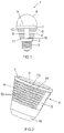
- FIG. 1 shows as a first embodiment of a lighting device 1 according to the invention a so-called LED retrofit lamp 1 in a lateral sectional image representation.
- the lamp 1 has a conventional screw base 2 (so-called. Edison thread), a driver electronics 3, a heat sink 4, LEDs (LED) 5 as a light source 5, and a piston 6, which protects the LEDs 5 from environmental influences.
- the outer contour of the retrofit lamp 1 is modeled on a conventional light bulb.
- the LEDs 5 are arranged on a first planar base 7 of the heat sink 4 and emit in the upper half-space.
- the heat sink 4 On the side facing away from the LED 5 8 of the first base 7, the heat sink 4 has two side bars 9, of which only the front is visible here.
- a second planar base 11 which carries the driver electronics 3 and thus serves for the cooling thereof, is arranged parallel thereto.
- the fan 13 is designed as an axial fan 13 and generates an air flow parallel to the plane of the base 7, the air from the left side penetrates into the lamp 1 and exits on the right side again.
- the lower part 14 of the lamp 1 is in FIG. 2 reproduced in a perspective view.
- the LEDs 5 are mounted on the upper base 7.
- the two side webs 9 and the axial fan 13 arranged in a cavity 15 of the heat sink 4 can be seen.
- the cooling fins 12 serve at the same time as protection of the fan 13 against contact and against the penetration of foreign bodies.
- the driver electronics 3 is for safety reasons arranged in a closed housing 16 made of an electrically insulating material.
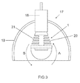
- FIG. 3 shows the arrangement of such a lamp 1 in a suspension lamp 17, which consists essentially of a socket 18 and a lampshade 19.
- a suspension lamp 17 which consists essentially of a socket 18 and a lampshade 19.
- a and B the air flow of the sucked cold air (A) and the ejected heated air (B) symbolized. It can clearly be seen that a direct suction of the blown-out heated air is reliably prevented by the arrangement of the suction port 20 and the exhaust port 21 on opposite sides of the lamp 1.
- FIG. 4 shows three different configurations of the cavity 15, in which the axial fan 13 is disposed between the two side bars 9.
- the cavity 15 is used by the free air space in front of and behind the fan 13 to improve its efficiency and reduce noise.
- the cavity 15 in a plane parallel to the plane of the first base 7 has a circular cross-section.
- the cooling fins 12 are the same width over their entire circumference, which ensures good heat dissipation.
- Middle of the cross-section of the cavity 15 is square, which facilitates the installation of the fan 13 and also allows the use of fans 13 of different thickness d due to the large installation space.
- the cavity 15 in the present embodiment has a rectangular cross-section, since in this the fan 13 can be used well and a simple shaping facilitates the production of the heat sink 4. But there are also other cross-sectional shapes conceivable.
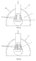
- FIG. 5 shows a further embodiment of a lighting device 1 according to the invention, also installed in a suspension lamp 17.
- the cooling fins 12 are mounted slightly obliquely, with the distance from the first base 7 decreases towards the outside.
- the air flow although in contrast to the previous embodiment no longer completely straight, but is still deflected by less than 90 °, ie less than in the lighting device according to the prior art.
- An advantage of this arrangement is the suction or ejection direction of the cooling air, which is directed away from the base 2 of the lamp 1, thereby causing a more effective cooling, in particular when using an open lampshade 19.
- FIG. 6 a further embodiment is shown in which the cooling fins 12 are not oriented parallel to the first base 7, but approximately perpendicular thereto. This can be dispensed with side bars 9. The arrangement of the cooling fins 12 approximately parallel to the desired air flow direction a good air flow and thus a good cooling effect is achieved.
- the arrangement of the cooling fins 12 may differ from those shown by, for example, also mixed forms with vertical and arranged parallel to the base 7 cooling fins 12 or the use of cooling pins are conceivable.
- the arrangement of the side webs 9 as well as the attachment of the fan 13 may vary.
- the person skilled in the art is also familiar with other devices for generating a cooling medium flow, in particular radial fans, systems based on a vibrating membrane or accelerated ions.
- Embodiments are also conceivable in which a second base 11 can be dispensed with because, for example, the driver electronics 3 are arranged on the base 7 carrying the LEDs 5.
- a thermal division of the heat sink 4 is conceivable, so that a heat transfer from the standing with the driver electronics 3 in operative connection part is suppressed or reduced to the standing with the light source 5 in operative connection part. As a result, a different degrees of cooling of the two components is possible.
Description
- Die Erfindung betrifft eine Beleuchtungsvorrichtung mit mindestens einem Kühlkörper und einer vorzugsweise zumindest annähernd ebenen Basis zur Aufnahme mindestens einer Lichtquelle sowie mindestens einer mit der Beleuchtungsvorrichtung verbundenen Vorrichtung zur Erzeugung eines Kühlmedienstroms, insbesondere eines Luftstroms.
- Beleuchtungsvorrichtungen benötigen, insbesondere wenn diese zur Lichterzeugung Leuchtdioden (LEDs) verwenden, häufig eine Kühlvorrichtung, mit der die Lichtquellen im Betrieb gekühlt werden können, damit diese eine lange Lebensdauer besitzen und die gewünschte Beleuchtungsqualität erreicht wird. Dazu weisen die Kühlvorrichtungen zumeist eine bevorzugt ebene Basis auf, auf der die LEDs direkt oder auf einem geeigneten Träger angebracht sind.
- Bei höheren Leistungen reichen passive Kühlkörper nicht mehr aus, um den gewünschten Kühleffekt sicherzustellen und es werden zumeist Vorrichtungen zur Erzeugung eines Kühlmedienstroms verwendet, die die Abfuhr von Wärmeleistung durch Konvektion verbessern. In der einfachsten und verbreitetsten Form werden dafür elektrische Lüfter eingesetzt, die auf der der Basis abgewandten Seite des Kühlkörpers montiert sind und Umgebungsluft als Kühlfluid annähernd senkrecht auf den Kühlkörper blasen. Der Kühlluftstrom wird dabei senkrecht zur Ebene der Basis auf den Kühlkörper geleitet und beim Auftreffen auf diesen dann zur Seite abgelenkt.
- Die
US 2007/0297183A1 und dieUS 2005/0174780 A1 zeigen Beispiele für Beleuchtungsvorrichtungen bei denen ein Kühlmedienstrom umgelenkt wird und entlang einer gewölbten Basis geführt wird. DieUS 2009/052175 A1 , dieEP 2 020 569 A2 und dieDE 20 2007 002751 U1 zeigen weiteren Stand der Technik zur Anordnung von Kühlvorrichtungen in Beleuchtungsvorrichtung. - Aufgrund der Ablenkung des Kühlluftstroms ergeben sich höhere Drücke und geringe Strömungsgeschwindigkeiten, wodurch eine schlechte Kühlwirkung erzielt wird. Wird zudem der Luftstrom nicht genau senkrecht auf den Kühlkörper geleitet, beispielsweise aufgrund einer leichten Schiefstellung des Lüfters in Relation zum Kühlkörper, kann es aufgrund des ungleichmäßigen Abflusses der Luft zu einer ungleichmäßigen Kühlung des Kühlkörpers und damit zu einer unerwünschten inhomogenen Temperaturverteilung kommen.
- Besonders wichtig ist eine optimale Kühlwirkung bei so genannten Retrofit-Lampen, die Leuchtdioden als Lichtquellen und einen herkömmlichen Lampensockel aufweisen, um sie anstelle herkömmlicher Glühlampen verwenden zu können. Diese Retrofit-Lampen sollen in ihren äußeren Abmessungen möglichst genau herkömmlichen Glühlampen entsprechen und müssen daher einen besonders kompakten Aufbau besitzen und möglichst in allen Einbaulagen funktionieren. Dies begünstigt das Auftreten eines thermischen Kurzschlusses, d.h. das direkte Ansaugen der gerade ausgeblasenen erwärmten Kühlluft, zumal wenn die Lampen in räumlich beengten Verhältnissen, beispielsweise aufgrund eines Lampenschirms, betrieben werden.
- Die Aufgabe der vorliegenden Erfindung ist es daher, eine Beleuchtungsvorrichtung mit mindestens einem Kühlkörper und einer Basis zur Aufnahme mindestens einer Lichtquelle sowie mindestens einer mit der Beleuchtungsvorrichtung verbundenen Vorrichtung zur Erzeugung eines Kühlmedienstroms, insbesondere eines Luftstroms zu schaffen, die eine kompakte Bauweise und einen hohen Wirkungsgrad bei der Kühlung der Lichtquelle aufweist.
- Diese Aufgabe wird hinsichtlich der Beleuchtungsvorrichtung gelöst durch die kennzeichnenden Merkmale des Anspruchs 1.
- Besonders vorteilhafte Ausgestaltungen finden sich in den abhängigen Ansprüchen.
- Indem der Kühlmedienstrom vorwiegend parallel zur Ebene der Basis des Kühlkörpers verläuft, wird eine Umlenkung des Luftstroms um einen größeren Winkel, insbesondere um mehr als 90°, vermieden. Dadurch wird die Kühlwirkung bei gleicher Lüfterleistung gegenüber einer Ausführung nach dem Stand der Technik wesentlich gesteigert. Zudem ist bei einer derartigen Anordnung der Verlauf der Strömung und damit die Kühlwirkung einfacher berechenbar und auch wesentlich unempfindlicher gegenüber einer Fehlstellung des Lüfters. Als Basis ist dabei der Bereich des Kühlkörpers zu sehen, der zur Befestigung von Bauteilen vorgesehen ist. Zweckmäßigerweise ist diese Basis zumindest annähernd eben, da so eine besonders einfache Anordnung erzielt wird, bei der beispielsweise auf Trägerplatten vormontierte Leuchtdioden verwendet werden können. Es sind aber auch konvex geformte Basen denkbar. Bei diesen ist als Ebene dann die Ebene zu sehen, bei der die Summe der Abstände der Punkte der Basis, die oberhalb der Ebene liegen, gleich der Summe der Abstände der Punkte der Basis, die unterhalb der Ebene liegen, ist.
- Wenn die Beleuchtungsvorrichtung ausschließlich auf einer Basis des Kühlkörpers angeordnet sind, wird ein besonders einfacher Aufbau erzielt.
- Es ist besonders vorteilhaft, wenn der Kühlmedienstrom im Wesentlichen von einer Seitenfläche der Beleuchtungsvorrichtung zur gegenüberliegenden Seitenfläche der Beleuchtungsvorrichtung verläuft. Durch diesen Weg des Kühlmedienstroms wird eine besonders große Distanz zwischen Kühlmedieneintritt und Kühlmedienaustritt aus der Beleuchtungsvorrichtung erreicht und somit das erneute Ansaugen erwärmten Kühlmediums (so genannter thermischer Kurzschluss) vermieden. Dies ist insbesondere bei Verwendung von Umgebungsluft als Kühlmedium vorteilhaft, da diese im Gegensatz zu anderen Kühlmedien besonders schlecht kontrollierbar ist. Als Seitenflächen sind dabei insbesondere die äußeren Begrenzungen der Beleuchtungsvorrichtung anzusehen, die senkrecht zu einer Hauptabstrahlrichtung der Lichtquellen oder senkrecht zu einer Längsachse der Beleuchtungsvorrichtung angeordnet sind. Bei Retrofitlampen sind dies zumeist die Seitenwände, die zwischen Sockel und Lichtquelle angeordnet sind.
- Indem die Vorrichtung zur Erzeugung des Kühlmedienstroms in einer Kavität des Kühlkörpers angeordnet ist, wird ein besonders kompakter Aufbau erzielt. Die Vorrichtung zur Erzeugung des Kühlluftstroms liegt somit innerhalb der Außenkontur des Kühlkörpers, ist bevorzugt sogar vollständig vom Kühlkörper umschlossen und damit besonders gut vor Umgebungseinflüssen geschützt.
- Zweckmäßigerweise weist der Kühlkörper Kühlfinnen und/oder Kühlstifte auf. Dadurch wird die vom Kühlmedienstrom überstrichene Oberfläche maximiert. Durch geeignete Formgebung der Kühlfinnen und/oder Kühlstifte kann zudem der Verlauf des Kühlmedienstroms optimiert werden
- Indem die die Kühlfinnen und/oder Kühlstifte zumindest annähernd parallel zu einer Ebene senkrecht zur Basis des Kühlkörpers angeordnet sind, ist sichergestellt, dass der Kühlmedienstrom in der gewünschten Richtung verläuft und dennoch eine sehr gute thermische Anbindung der Kühlfinnen und/oder Kühlstifte an die Basis des Kühlkörpers gegeben ist.
- Wenn die Kühlfinnen und/oder Kühlstifte annähernd parallel zur Ebene der Basis des Kühlkörpers angeordnet sind, wird die Strömung des Kühlmedienstroms ebenfalls in vorteilhafter Weise geführt.
- Vorteilhafterweise weist der Kühlkörper mindestens einen Seitensteg auf. Dieser Seitensteg ist besonders gut geeignet, um andere Komponenten des Kühlkörpers zu halten. Auch kann ein Seitensteg dazu dienen, den Kühlkörper an anderen Bauteilen zu befestigen.
- Zweckmäßigerweise sind die Kühlfinnen und/oder Kühlstifte zumindest teilweise an dem Seitensteg angeordnet. Dadurch können Kühlfinnen auch entfernt von der Basis angeordnet werden, was zu einer verbesserten Wärmeabfuhr führt, da dort die Temperatur der vorbeiströmenden Luft zumeist niedriger als nahe der Basis ist.
- Zweckmäßigerweise weist der Kühlkörper mindestens eine zweite Basis auf. Diese Basis kann dazu dienen, weitere zu kühlende Komponenten aufzunehmen, wie beispielsweise weitere Lichtquellen.
- In einer zweckmäßigen Weiterbildung der Erfindung steht die zweite Basis mit mindestens einer elektrischen Schaltung, vorzugsweise einer Treiberschaltung zum Betrieb mindestens einer Lichtquelle der Beleuchtungsvorrichtung, thermisch in Wirkverbindung. Derartige Komponenten können im Betrieb ebenfalls erhebliche Abwärme entwickeln und werden somit effektiv durch den Kühlkörper gekühlt. Durch die Verwendung einer zweiten Basis dient der Kühlkörper als Verbindungsglied zwischen Lichtquelle und Treiberschaltung, was einen kompakten und einfachen Aufbau bewirkt.
- Zweckmäßigerweise ist dabei die elektrische Schaltung auf der mindestens zweiten Basis angeordnet, da so ein ganz besonders einfacher Aufbau erzielt wird.
- Es ist weiterhin von Vorteil, wenn die Vorrichtung zur Erzeugung des Kühlmedienstroms als elektrisch betreibbarer Lüfter, insbesondere als Axiallüfter oder als Radiallüfter, ausgebildet ist. Derartige Lüfter sind einfach und effektiv. Es kann aber auch vorteilhaft sein, eine mittels einer schwingenden Membran oder mittels beschleunigter Ionen wirkende Lüftungsvorrichtung zu verwenden.
- Vorteilhafterweise ist die Vorrichtung zur Erzeugung des Kühlmedienstroms in einer Kavität des Kühlkörpers angeordnet. Dadurch wird ein kompakter Aufbau erzielt und die Vorrichtung zur Erzeugung des Kühlmedienstroms zuverlässig vor Umgebungseinflüssen, insbesondere dem Eindringen von Fremdkörpern oder Berührung, geschützt.
- Indem die Kavität zumindest abschnittsweise einen quadratischen oder kreisförmigen Querschnitt aufweist, wird eine einfache Formgebung erzielt, die insbesondere zur Aufnahme handelsüblicher elektrischer Lüfter gut geeignet ist.
- Indem die Vorrichtung zur Erzeugung des Kühlmedienstroms an mindestens einem der Seitenstege angeordnet ist, wird diese einfach und zuverlässig an den Kühlkörper angebunden.
- Weiterhin ist es von Vorteil, wenn die Beleuchtungsvorrichtung mindestens einen genormten Sockel zur Aufnahme in einer genormten Fassung aufweist. Damit kann die Beleuchtungsvorrichtung anstelle einer anderen Lichtquelle, wie beispielsweise einer Glühlampe oder einer Leuchtstofflampe, beispielsweise in herkömmlichen Leuchten eingebaut werden.
- Die Wirkungen der Erfindung kommen in besonders vorteilhafter Weise zum Tragen, wenn die Beleuchtungsvorrichtung Leuchtdioden als Lichtquelle aufweist und/oder als so genannte Retrofit-Lampe ausgebildet ist. Retrofit-Lampen können anstelle herkömmlicher Glühlampen verwendet werden und sind in ihren äußeren Abmessungen diesen nachempfunden. Dadurch müssen diese einen besonders kompakten Aufbau besitzen und möglichst in allen Einbaulagen funktionieren. Häufig weisen Retrofit-Lampen die herkömmliche Glühlampenform (Birne) auf, es sind aber insbesondere auch sog. Kerzenlampen oder auch Reflektorlampen, d.h. Lampen, bei denen mittels eines Reflektors eine gerichtete Lichtabgabe erzielt wird, darunter zu verstehen. Auch Linienlampen, d.h. Lampen mit einer linearen Ausdehnung, können darunter fallen.
- Im Folgenden soll die Erfindung anhand von Ausführungsbeispielen näher erläutert werden. Die Figuren zeigen:
- Fig. 1
- Ein erstes Ausführungsbeispiel einer erfindungsgemäßen Beleuchtungsvorrichtung,
- Fig. 2
- eine Teilansicht der Beleuchtungsvorrichtung gemäß
Figur 1 in perspektivischer Darstellung, - Fig. 3
- die Beleuchtungsvorrichtung gemäß
Figur 1 installiert in einer typischen Leuchte, - Fig. 4
- drei Ausführungen einer Beleuchtungsvorrichtung gemäß
Figur 1 in einer Schnittbilddarstellung, - Fig. 5
- eine weitere Ausfürhungsform einer erfindungsgemäßen Beleuchtungsvorrichtung installiert in einer typischen Leuchte,
- Fig. 6
- eine weitere Ausfürhungsform einer erfindungsgemäßen Beleuchtungsvorrichtung installiert in einer typischen Leuchte.
-
Figur 1 zeigt als erstes Ausführungsbeispiel einer erfindungsgemäßen Beleuchtungsvorrichtung 1 eine so genannte LED-Retrofit-Lampe 1 in einer seitlichen Schnittbilddarstellung. Die Lampe 1 besitzt einen herkömmlichen Schraubsockel 2 (sog. Edison-Gewinde), eine Treiberelektronik 3, einen Kühlkörper 4, Leuchtdioden (LED) 5 als Lichtquelle 5, sowie einen Kolben 6, der die LEDs 5 vor Umgebungseinflüssen schützt. Die Außenkontur der Retrofit-Lampe 1 ist einer herkömmlichen Glühlampe nachempfunden. Die LEDs 5 sind auf einer ersten ebenen Basis 7 des Kühlkörpers 4 angeordnet und strahlen in den oberen Halbraum ab. Auf der den LED 5 abgewandten Seite 8 der ersten Basis 7 weist der Kühlkörper 4 zwei Seitenstege 9 auf, von denen hier nur der vordere sichtbar ist. An dem der ersten Basis 7 abgewandten Ende 10 der Seitenstege 9 ist parallel dazu eine zweite ebene Basis 11 angeordnet, die die Treiberelektronik 3 trägt und somit zu deren Kühlung dient. - Seitlich an den Seitenstegen 9 sind Kühlfinnen 12 angebracht, die parallel zur Ebene der ersten Basis 7 verlaufen. Zwischen den Seitenstegen 9 ist ein hier nicht sichtbarer elektrischer Lüfter 13 angeordnet, der an den Seitenstegen 9 befestigt ist. Der Lüfter 13 ist als Axiallüfter 13 ausgeführt und erzeugt einen Luftstrom parallel zur Ebene der Basis 7, wobei die Luft von der linken Seite in die Lampe 1 eindringt und auf der rechten Seite wieder austritt.
- Der untere Teil 14 der Lampe 1 ist in
Figur 2 in einer perspektivischen Ansicht wiedergegeben. Auf der oberen Basis 7 sind die Leuchtdioden 5 angebracht. Deutlich sind die beiden Seitenstege 9 sowie der in einer Kavität 15 des Kühlkörpers 4 angeordnete Axiallüfter 13 zu erkennen. Die Kühlfinnen 12 dienen zugleich als Schutz des Lüfters 13 vor Berührung sowie vor dem Eindringen von Fremdkörpern. Die Treiberelektronik 3 ist aus Sicherheitsgründen in einem geschlossenen Gehäuse 16 aus einem elektrisch isolierendem Werkstoff angeordnet. -
Figur 3 zeigt die Anordnung einer derartigen Lampe 1 in einer Hängeleuchte 17, die im Wesentlichen aus einer Fassung 18 sowie einem Leuchtenschirm 19 besteht. Durch Pfeile A und B ist der Luftstrom der angesaugten kalten Luft (A) sowie der ausgestoßenen erwärmten Luft (B) symbolisiert. Deutlich ist zu erkennen, dass durch die Anordnung der Ansaugöffnung 20 und der Abluftöffnung 21 an gegenüberliegenden Seiten der Lampe 1 ein direktes Ansaugen der ausgeblasenen erwärmten Luft zuverlässig verhindert wird. -
Figur 4 zeigt drei unterschiedliche Ausbildungen der Kavität 15, in der der Axiallüfter 13 zwischen den beiden Seitenstegen 9 angeordnet ist. Die Kavität 15 dient durch den freien Luftraum vor und hinter dem Lüfter 13 dazu, dessen Wirkungsgrad zu verbessern und die Geräuschentwicklung zu reduzieren. InFigur 4 oben weist die Kavität 15 in einer Ebene parallel zur Ebene der ersten Basis 7 einen kreisförmigen Querschnitt auf. Dadurch sind die Kühlfinnen 12 über ihren gesamten Umfang gleich breit, was eine gute Wärmeabfuhr gewährleistet. InFigur 4 Mitte ist der Querschnitt der Kavität 15 quadratisch, was den Einbau des Lüfters 13 erleichtert und durch den großen Einbauraum auch die Verwendung von Lüftern 13 unterschiedlicher Dicke d zulässt.Figur 4 unten zeigt eine andere Ausführungsform einer quadratischen Querschnittsfläche, bei der die Breite der Kühlfinnen 12 zu der außen liegenden und damit kältesten Stelle hin abnimmt, was eine gute Wärmeabfuhr bei geringem Materialeinsatz für die Kühlfinnen 12 sicherstellt. Senkrecht zur Ebene des Basis 7 weist die Kavität 15 im vorliegenden Ausführungsbeispiel einen rechteckigen Querschnitt auf, da sich in diesen der Lüfter 13 gut einsetzen lässt und eine einfache Formgebung die Herstellung des Kühlkörpers 4 erleichtert. Es sind aber auch andere Querschnittsformen denkbar. -
Figur 5 zeigt ein weiteres Ausführungsbeispiel einer erfindungsgemäßen Beleuchtungsvorrichtung 1, ebenfalls installiert in einer Hängeleuchte 17. Bei dieser Ausführungsform sind die Kühlfinnen 12 leicht schräg angebracht, wobei nach außen hin der Abstand von der ersten Basis 7 abnimmt. Bei dieser Ausführungsform ist der Luftstrom zwar im Gegensatz zum vorherigen Ausführungsbeispiel nicht mehr vollständig gerade, wird jedoch noch um weniger als 90° abgelenkt, d.h. weniger als bei Beleuchtungsvorrichtung nach dem Stand der Technik. Vorteilhaft bei dieser Anordnung ist die Ansaug- bzw. Ausstoßrichtung der Kühlluft, die vom Sockel 2 der Lampe 1 weg gerichtet ist und dadurch insbesondere bei Verwendung eines offenen Leuchtenschirms 19 eine effektivere Kühlung bewirkt. - In
Figur 6 ist ein weiteres Ausführungsbeispiel gezeigt, bei dem die Kühlfinnen 12 nicht parallel zur ersten Basis 7 orientiert sind, sondern annähernd senkrecht dazu. Damit kann auf Seitenstege 9 verzichtet werden. Durch die Anordnung der Kühlfinnen 12 annähernd parallel zur gewünschten Luftstromrichtung wird eine gute Luftführung und damit eine gute Kühlwirkung erzielt. - Selbstverständlich sind noch andere erfindungsgemäße Beleuchtungsvorrichtungen 1 denkbar. So kann beispielsweise die Anordnung der Kühlfinnen 12 von den gezeigten abweichen, indem beispielsweise auch Mischformen mit senkrecht und parallel zur Basis 7 angeordneten Kühlfinnen 12 oder auch die Verwendung von Kühlstiften denkbar sind. Auch die Anordnung der Seitenstege 9 wie auch die Befestigung des Lüfters 13 kann variieren. Anstelle des Axiallüfters 13 sind dem Fachmann auch weitere Vorrichtungen zur Erzeugung eines Kühlmedienstroms bekannt, insbesondere Radiallüfter, Systeme auf Basis einer schwingenden Membran oder von beschleunigten Ionen. Auch sind Ausführungsformen denkbar, bei denen auf eine zweite Basis 11 verzichtet werden kann, weil beispielsweise die Treiberelektronik 3 auf der die LEDs 5 tragenden Basis 7 angeordnet ist. Auch eine thermische Teilung des Kühlkörpers 4 ist denkbar, so dass eine Wärmeübertragung von dem mit der Treiberelektronik 3 in Wirkverbindung stehenden Teil zu dem mit der Lichtquelle 5 in Wirkverbindung stehenden Teil unterbunden oder reduziert wird. Dadurch ist eine unterschiedlich starke Kühlung der beiden Komponenten möglich.
Claims (13)
- Beleuchtungsvorrichtung (1) mit mindestens einem Kühlkörper (4) und einer Basis (7) zur Aufnahme mindestens einer Lichtquelle (5) sowie mindestens einer mit der Beleuchtungsvorrichtung (1) verbundenen Vorrichtung (13) zur Erzeugung eines Kühlmedienstroms, insbesondere eines Luftstroms, wobei der Kühlmedienstrom vorwiegend parallel zur Ebene der vorzugsweise zumindest annähernd ebenen Basis (7) des Kühlkörpers (4) verläuft, dadurch gekennzeichnet, dass die Vorrichtung (13) zur Erzeugung des Kühlmedienstroms in einer Kavität (15) des Kühlkörpers (4) angeordnet ist und der Kühlmedienstrom im Wesentlichen von einer Seitenfläche der Beleuchtungsvorrichtung zur gegenüberliegenden Seitenfläche der Beleuchtungsvorrichtung verläuft.
- Beleuchtungsvorrichtung nach Anspruch 1, dadurch gekennzeichnet, dass der Kühlmedienstrom im Wesentlichen von einer Seitenfläche der Beleuchtungsvorrichtung zur gegenüberliegenden Seitenfläche der Beleuchtungsvorrichtung verläuft.
- Beleuchtungsvorrichtung (1) nach einem der Ansprüche 1 oder 2, dadurch gekennzeichnet, dass der Kühlkörper (4) Kühlfinnen (12) und/oder Kühlstifte aufweist.
- Beleuchtungsvorrichtung (1) nach Anspruch 3, dadurch gekennzeichnet, dass die Kühlfinnen (12) und/oder Kühlstifte zumindest annähernd parallel zu einer Ebene senkrecht zur Basis (7) des Kühlkörpers (4) angeordnet sind.
- Beleuchtungsvorrichtung (1) nach einem der Ansprüche 3 oder 4, dadurch gekennzeichnet, dass die Kühlfinnen (12) und/oder Kühlstifte annähernd parallel zur Ebene der Basis (7) des Kühlkörpers (4) angeordnet sind.
- Beleuchtungsvorrichtung (1) nach einem der Ansprüche 1 bis 5, dadurch gekennzeichnet, dass der Kühlkörper (4) mindestens einen Seitensteg (9) aufweist.
- Beleuchtungsvorrichtung (1) nach Anspruch 6, dadurch gekennzeichnet, dass die Kühlfinnen (12) und/oder Kühlstifte zumindest teilweise an dem Seitensteg (9) angeordnet sind.
- Beleuchtungsvorrichtung (1) nach einem der Ansprüche 1 bis 7, dadurch gekennzeichnet, dass der Kühlkörper (4) mindestens eine zweite Basis (11) aufweist.
- Beleuchtungsvorrichtung (1) nach Anspruch 8, dadurch gekennzeichnet, dass die zweite Basis (11) mit mindestens einer elektrischen Schaltung (3), vorzugsweise einer Treiberschaltung (3) zum Betrieb mindestens einer Lichtquelle (5) der Beleuchtungsvorrichtung (1) thermisch in Wirkverbindung steht.
- Beleuchtungsvorrichtung (1) nach einem der Ansprüche 8 oder 9, dadurch gekennzeichnet, dass die elektrische Schaltung (3) auf der mindestens zweiten Basis (11) angeordnet ist.
- Beleuchtungsvorrichtung (1) nach einem der Ansprüche 1 bis 10, dadurch gekennzeichnet, dass die Kavität (15) zumindest abschnittsweise einen quadratischen oder kreisförmigen Querschnitt aufweist.
- Beleuchtungsvorrichtung (1) nach einem der Ansprüche 6 bis 11, dadurch gekennzeichnet, dass die Vorrichtung (13) zur Erzeugung des Kühlmedienstroms an mindestens einem der Seitenstege (9) angeordnet ist.
- Beleuchtungsvorrichtung (1) nach einem der Ansprüche 1 bis 12, dadurch gekennzeichnet, dass die Beleuchtungsvorrichtung mindestens einen genormten Sockel zur Aufnahme in einer genormten Fassung aufweist.
Applications Claiming Priority (2)
| Application Number | Priority Date | Filing Date | Title |
|---|---|---|---|
| DE102009011350A DE102009011350A1 (de) | 2009-03-05 | 2009-03-05 | Beleuchtungsvorrichtung mit mindestens einem Kühlkörper |
| PCT/EP2010/052648 WO2010100169A1 (de) | 2009-03-05 | 2010-03-03 | Beleuchtungsvorrichtung mit mindestens einem kühlkörper |
Publications (2)
| Publication Number | Publication Date |
|---|---|
| EP2404110A1 EP2404110A1 (de) | 2012-01-11 |
| EP2404110B1 true EP2404110B1 (de) | 2016-08-17 |
Family
ID=42062602
Family Applications (1)
| Application Number | Title | Priority Date | Filing Date |
|---|---|---|---|
| EP10706629.2A Not-in-force EP2404110B1 (de) | 2009-03-05 | 2010-03-03 | Beleuchtungsvorrichtung mit mindestens einem kühlkörper |
Country Status (5)
| Country | Link |
|---|---|
| US (1) | US9677753B2 (de) |
| EP (1) | EP2404110B1 (de) |
| CN (1) | CN102341649B (de) |
| DE (1) | DE102009011350A1 (de) |
| WO (1) | WO2010100169A1 (de) |
Families Citing this family (18)
| Publication number | Priority date | Publication date | Assignee | Title |
|---|---|---|---|---|
| DE102010063550A1 (de) * | 2010-12-20 | 2012-06-21 | Tridonic Jennersdorf Gmbh | Kühlsystem und Verfahren für elektronische Komponenten |
| RU2604647C2 (ru) | 2011-04-29 | 2016-12-10 | Конинклейке Филипс Н.В. | Осветительное сид-устройство с верхней структурой рассеивания тепла |
| RU2604660C2 (ru) | 2011-04-29 | 2016-12-10 | Конинклейке Филипс Н.В. | Светодиодное осветительное устройство с нижней теплорассеивающей конструкцией |
| US9157585B2 (en) | 2012-03-28 | 2015-10-13 | Milwaukee Electric Tool Corporation | Area light |
| US9091402B2 (en) | 2012-03-28 | 2015-07-28 | Milwaukee Electric Tool Corporation | Area light |
| USD779694S1 (en) | 2013-08-27 | 2017-02-21 | Milwaukee Electric Tool Corporation | Portable light |
| CN208764695U (zh) | 2015-02-04 | 2019-04-19 | 米沃奇电动工具公司 | 灯 |
| US10378739B2 (en) | 2015-04-24 | 2019-08-13 | Milwaukee Electric Tool Corporation | Stand light |
| US10775032B2 (en) | 2015-07-01 | 2020-09-15 | Milwaukee Electric Tool Corporation | Area light |
| US10323831B2 (en) | 2015-11-13 | 2019-06-18 | Milwaukee Electric Tool Corporation | Utility mount light |
| USD816252S1 (en) | 2016-05-16 | 2018-04-24 | Milwaukee Electric Tool Corporation | Light |
| EP3260775B1 (de) * | 2016-06-23 | 2019-03-13 | OSRAM GmbH | Kühlkörper, zugehörige beleuchtungsvorrichtung und verfahren zur verwendung davon |
| IT201900022209A1 (it) | 2019-11-26 | 2021-05-26 | Osram Gmbh | Lampada e procedimento corrispondente |
| USD987167S1 (en) * | 2020-03-23 | 2023-05-23 | Osram Gmbh | Heatsink for a lamp |
| DE102020203736A1 (de) | 2020-03-23 | 2021-09-23 | Osram Gmbh | Halbleiter-Retrofit-Fahrzeugscheinwerferlampe |
| DE102020203735A1 (de) | 2020-03-23 | 2021-09-23 | Osram Gmbh | Fahrzeug-Retrofit-Scheinwerferlampe mit einander zugewandten Reflektorbereichen |
| DE102020203733A1 (de) | 2020-03-23 | 2021-09-23 | Osram Gmbh | Reflektoroptik für eine Fahrzeug-Retrofit-Scheinwerferlampe |
| DE102020130660A1 (de) | 2020-11-19 | 2022-05-19 | Osram Gmbh | Fahrzeug-retrofit-scheinwerferlampe mit halbleiterlichtquellen in matrixanordnung |
Citations (3)
| Publication number | Priority date | Publication date | Assignee | Title |
|---|---|---|---|---|
| DE202007002751U1 (de) * | 2007-02-24 | 2007-04-26 | Chen, Bor-Jang, Pyng-Jenn City | Kühlvorrichtung einer Lampe |
| EP2020569A2 (de) * | 2007-08-01 | 2009-02-04 | odelo GmbH | Scheinwerfersystem mit gesteuerter und/oder geregelter Beschlagverminderungsvorrichtung |
| US20090052175A1 (en) * | 2007-08-24 | 2009-02-26 | Fu Zhun Precision Industry (Shen Zhen) Co., Ltd. | Led lamp with a heat dissipation device |
Family Cites Families (20)
| Publication number | Priority date | Publication date | Assignee | Title |
|---|---|---|---|---|
| JP2004296245A (ja) * | 2003-03-26 | 2004-10-21 | Matsushita Electric Works Ltd | Ledランプ |
| KR200350484Y1 (ko) * | 2004-02-06 | 2004-05-13 | 주식회사 대진디엠피 | 콘상 엘이디 조명등 |
| CA2558222C (en) * | 2004-03-03 | 2009-10-13 | S. C. Johnson & Son, Inc. | Led light bulb with active ingredient emission |
| US20070253202A1 (en) * | 2006-04-28 | 2007-11-01 | Chaun-Choung Technology Corp. | LED lamp and heat-dissipating structure thereof |
| KR100754405B1 (ko) * | 2006-06-01 | 2007-08-31 | 삼성전자주식회사 | 조명기구 |
| US7682052B2 (en) | 2006-06-21 | 2010-03-23 | Osram Sylvania Inc. | Heat sink |
| US20080123340A1 (en) * | 2006-11-27 | 2008-05-29 | Mcclellan Thomas | Light device having LED illumination and electronic circuit board in an enclosure |
| US20080149305A1 (en) * | 2006-12-20 | 2008-06-26 | Te-Chung Chen | Heat Sink Structure for High Power LED Lamp |
| JP2008186758A (ja) | 2007-01-31 | 2008-08-14 | Royal Lighting Co Ltd | 電球形照明用ledランプ |
| US20100219734A1 (en) * | 2007-06-08 | 2010-09-02 | Superbulbs, Inc. | Apparatus for cooling leds in a bulb |
| DE102007037862A1 (de) * | 2007-08-10 | 2008-10-30 | Siemens Ag | Entwärmung mittels einer Membranpumpe |
| DE102007040444B8 (de) * | 2007-08-28 | 2013-10-17 | Osram Gmbh | LED-Lampe |
| CN101861759B (zh) * | 2007-10-09 | 2012-11-28 | 飞利浦固体状态照明技术公司 | 用于控制多串联负载中的各个负载电流的方法和设备 |
| CN201110529Y (zh) * | 2007-10-15 | 2008-09-03 | 协禧电机股份有限公司 | 具风扇散热功用的发光二极管灯 |
| DE202008000360U1 (de) * | 2008-01-09 | 2008-05-21 | Käppel, Volker | Leuchte mit einem Leuchtgehäuse in Form eines Hohlprofils |
| CN201187758Y (zh) * | 2008-04-03 | 2009-01-28 | 富准精密工业(深圳)有限公司 | 发光二极管灯具 |
| CN101566326B (zh) * | 2008-04-23 | 2012-09-19 | 富准精密工业(深圳)有限公司 | 照明装置及其光引擎 |
| TWI363850B (en) * | 2008-05-28 | 2012-05-11 | Delta Electronics Inc | Illuminating device and heat-dissipating structure thereof |
| TW201002994A (en) * | 2008-07-04 | 2010-01-16 | Delta Electronics Inc | Illuminating device and annular heat-dissipating structure thereof |
| US7575346B1 (en) | 2008-07-22 | 2009-08-18 | Sunonwealth Electric Machine Industry Co., Ltd. | Lamp |
-
2009
- 2009-03-05 DE DE102009011350A patent/DE102009011350A1/de not_active Ceased
-
2010
- 2010-03-03 EP EP10706629.2A patent/EP2404110B1/de not_active Not-in-force
- 2010-03-03 CN CN201080010660.8A patent/CN102341649B/zh not_active Expired - Fee Related
- 2010-03-03 WO PCT/EP2010/052648 patent/WO2010100169A1/de active Application Filing
- 2010-03-03 US US13/254,853 patent/US9677753B2/en not_active Expired - Fee Related
Patent Citations (3)
| Publication number | Priority date | Publication date | Assignee | Title |
|---|---|---|---|---|
| DE202007002751U1 (de) * | 2007-02-24 | 2007-04-26 | Chen, Bor-Jang, Pyng-Jenn City | Kühlvorrichtung einer Lampe |
| EP2020569A2 (de) * | 2007-08-01 | 2009-02-04 | odelo GmbH | Scheinwerfersystem mit gesteuerter und/oder geregelter Beschlagverminderungsvorrichtung |
| US20090052175A1 (en) * | 2007-08-24 | 2009-02-26 | Fu Zhun Precision Industry (Shen Zhen) Co., Ltd. | Led lamp with a heat dissipation device |
Also Published As
| Publication number | Publication date |
|---|---|
| DE102009011350A1 (de) | 2010-09-09 |
| WO2010100169A1 (de) | 2010-09-10 |
| EP2404110A1 (de) | 2012-01-11 |
| CN102341649B (zh) | 2015-08-19 |
| US20120044707A1 (en) | 2012-02-23 |
| CN102341649A (zh) | 2012-02-01 |
| US9677753B2 (en) | 2017-06-13 |
Similar Documents
| Publication | Publication Date | Title |
|---|---|---|
| EP2404110B1 (de) | Beleuchtungsvorrichtung mit mindestens einem kühlkörper | |
| DE102007030186B4 (de) | Lineare LED-Lampe und Leuchtensystem mit derselben | |
| WO2010089397A1 (de) | Kühlkörper für eine leuchtvorrichtung | |
| EP2556296B1 (de) | Leuchtengehäuse | |
| DE102006018668A1 (de) | Modulares Beleuchtungssystem und Beleuchtungsanordnung | |
| DE212013000200U1 (de) | Leuchte mit Luftleitflächen | |
| DE102010052020B4 (de) | Beleuchtungs- und/oder Anzeigenvorrichtung | |
| EP2270387B1 (de) | LED Flachleuchte | |
| DE102008003703B4 (de) | Leuchte mit einem Leuchtengehäuse in Form eines Hohlprofils | |
| DE202011107787U1 (de) | Lichtemissionsvorrichtung | |
| EP3911892B1 (de) | Leuchte mit umfangsseitig geschlossenem kühlkörper | |
| DE102018123968A1 (de) | Stiftförmige Kompaktleuchtstofflampe mit einer Light-Engine aus einem Streifen | |
| WO2012022662A1 (de) | Lichtquelle | |
| EP3399225B1 (de) | Tunnelleuchte | |
| DE202008000360U1 (de) | Leuchte mit einem Leuchtgehäuse in Form eines Hohlprofils | |
| DE202014100998U1 (de) | LED-Leuchte und LED-Leuchten-Batterie | |
| DE102010054592B4 (de) | Kühlvorrichtung zum Kühlen von Bauteilen | |
| AT509626A1 (de) | Modulares led beleuchtungssystem mit partieller lichtstärkenanpassung | |
| DE202009005266U1 (de) | LED-Lampe mit hoher Wärmeabführleistung und Sicherheit | |
| WO2016058570A1 (de) | Led-strassenleuchte | |
| DE202017006973U1 (de) | Beleuchtungsvorrichtung | |
| DE202012009071U1 (de) | LED-Leuchte mit verbessertem Rückstrahlverhalten | |
| DE102017109836B4 (de) | Leuchtmittel mit Kühlkörper | |
| DE102017109840B4 (de) | LED-Retrofit-Lampe und Kühlkörper für eine LED-Retrofit-Lampe | |
| DE202012100848U1 (de) | LED-Leuchtmittel |
Legal Events
| Date | Code | Title | Description |
|---|---|---|---|
| PUAI | Public reference made under article 153(3) epc to a published international application that has entered the european phase |
Free format text: ORIGINAL CODE: 0009012 |
|
| 17P | Request for examination filed |
Effective date: 20110810 |
|
| AK | Designated contracting states |
Kind code of ref document: A1 Designated state(s): AT BE BG CH CY CZ DE DK EE ES FI FR GB GR HR HU IE IS IT LI LT LU LV MC MK MT NL NO PL PT RO SE SI SK SM TR |
|
| DAX | Request for extension of the european patent (deleted) | ||
| RAP1 | Party data changed (applicant data changed or rights of an application transferred) |
Owner name: OSRAM GMBH |
|
| RAP1 | Party data changed (applicant data changed or rights of an application transferred) |
Owner name: OSRAM GMBH |
|
| 17Q | First examination report despatched |
Effective date: 20140113 |
|
| REG | Reference to a national code |
Ref country code: DE Ref legal event code: R079 Ref document number: 502010012208 Country of ref document: DE Free format text: PREVIOUS MAIN CLASS: F21V0029020000 Ipc: F21V0029000000 |
|
| RIC1 | Information provided on ipc code assigned before grant |
Ipc: F21V 29/00 20150101AFI20160127BHEP |
|
| GRAP | Despatch of communication of intention to grant a patent |
Free format text: ORIGINAL CODE: EPIDOSNIGR1 |
|
| INTG | Intention to grant announced |
Effective date: 20160404 |
|
| GRAS | Grant fee paid |
Free format text: ORIGINAL CODE: EPIDOSNIGR3 |
|
| GRAA | (expected) grant |
Free format text: ORIGINAL CODE: 0009210 |
|
| AK | Designated contracting states |
Kind code of ref document: B1 Designated state(s): AT BE BG CH CY CZ DE DK EE ES FI FR GB GR HR HU IE IS IT LI LT LU LV MC MK MT NL NO PL PT RO SE SI SK SM TR |
|
| REG | Reference to a national code |
Ref country code: GB Ref legal event code: FG4D Free format text: NOT ENGLISH |
|
| REG | Reference to a national code |
Ref country code: CH Ref legal event code: EP |
|
| REG | Reference to a national code |
Ref country code: IE Ref legal event code: FG4D Free format text: LANGUAGE OF EP DOCUMENT: GERMAN |
|
| REG | Reference to a national code |
Ref country code: AT Ref legal event code: REF Ref document number: 821471 Country of ref document: AT Kind code of ref document: T Effective date: 20160915 |
|
| REG | Reference to a national code |
Ref country code: DE Ref legal event code: R096 Ref document number: 502010012208 Country of ref document: DE |
|
| REG | Reference to a national code |
Ref country code: CH Ref legal event code: NV Representative=s name: BOVARD AG, CH |
|
| REG | Reference to a national code |
Ref country code: NL Ref legal event code: FP |
|
| REG | Reference to a national code |
Ref country code: LT Ref legal event code: MG4D |
|
| PG25 | Lapsed in a contracting state [announced via postgrant information from national office to epo] |
Ref country code: NO Free format text: LAPSE BECAUSE OF FAILURE TO SUBMIT A TRANSLATION OF THE DESCRIPTION OR TO PAY THE FEE WITHIN THE PRESCRIBED TIME-LIMIT Effective date: 20161117 Ref country code: LT Free format text: LAPSE BECAUSE OF FAILURE TO SUBMIT A TRANSLATION OF THE DESCRIPTION OR TO PAY THE FEE WITHIN THE PRESCRIBED TIME-LIMIT Effective date: 20160817 Ref country code: IT Free format text: LAPSE BECAUSE OF FAILURE TO SUBMIT A TRANSLATION OF THE DESCRIPTION OR TO PAY THE FEE WITHIN THE PRESCRIBED TIME-LIMIT Effective date: 20160817 Ref country code: FI Free format text: LAPSE BECAUSE OF FAILURE TO SUBMIT A TRANSLATION OF THE DESCRIPTION OR TO PAY THE FEE WITHIN THE PRESCRIBED TIME-LIMIT Effective date: 20160817 Ref country code: HR Free format text: LAPSE BECAUSE OF FAILURE TO SUBMIT A TRANSLATION OF THE DESCRIPTION OR TO PAY THE FEE WITHIN THE PRESCRIBED TIME-LIMIT Effective date: 20160817 |
|
| PG25 | Lapsed in a contracting state [announced via postgrant information from national office to epo] |
Ref country code: GR Free format text: LAPSE BECAUSE OF FAILURE TO SUBMIT A TRANSLATION OF THE DESCRIPTION OR TO PAY THE FEE WITHIN THE PRESCRIBED TIME-LIMIT Effective date: 20161118 Ref country code: LV Free format text: LAPSE BECAUSE OF FAILURE TO SUBMIT A TRANSLATION OF THE DESCRIPTION OR TO PAY THE FEE WITHIN THE PRESCRIBED TIME-LIMIT Effective date: 20160817 Ref country code: SE Free format text: LAPSE BECAUSE OF FAILURE TO SUBMIT A TRANSLATION OF THE DESCRIPTION OR TO PAY THE FEE WITHIN THE PRESCRIBED TIME-LIMIT Effective date: 20160817 Ref country code: PL Free format text: LAPSE BECAUSE OF FAILURE TO SUBMIT A TRANSLATION OF THE DESCRIPTION OR TO PAY THE FEE WITHIN THE PRESCRIBED TIME-LIMIT Effective date: 20160817 Ref country code: PT Free format text: LAPSE BECAUSE OF FAILURE TO SUBMIT A TRANSLATION OF THE DESCRIPTION OR TO PAY THE FEE WITHIN THE PRESCRIBED TIME-LIMIT Effective date: 20161219 Ref country code: ES Free format text: LAPSE BECAUSE OF FAILURE TO SUBMIT A TRANSLATION OF THE DESCRIPTION OR TO PAY THE FEE WITHIN THE PRESCRIBED TIME-LIMIT Effective date: 20160817 |
|
| REG | Reference to a national code |
Ref country code: FR Ref legal event code: PLFP Year of fee payment: 8 |
|
| PG25 | Lapsed in a contracting state [announced via postgrant information from national office to epo] |
Ref country code: EE Free format text: LAPSE BECAUSE OF FAILURE TO SUBMIT A TRANSLATION OF THE DESCRIPTION OR TO PAY THE FEE WITHIN THE PRESCRIBED TIME-LIMIT Effective date: 20160817 Ref country code: RO Free format text: LAPSE BECAUSE OF FAILURE TO SUBMIT A TRANSLATION OF THE DESCRIPTION OR TO PAY THE FEE WITHIN THE PRESCRIBED TIME-LIMIT Effective date: 20160817 |
|
| REG | Reference to a national code |
Ref country code: DE Ref legal event code: R097 Ref document number: 502010012208 Country of ref document: DE |
|
| PG25 | Lapsed in a contracting state [announced via postgrant information from national office to epo] |
Ref country code: DK Free format text: LAPSE BECAUSE OF FAILURE TO SUBMIT A TRANSLATION OF THE DESCRIPTION OR TO PAY THE FEE WITHIN THE PRESCRIBED TIME-LIMIT Effective date: 20160817 Ref country code: CZ Free format text: LAPSE BECAUSE OF FAILURE TO SUBMIT A TRANSLATION OF THE DESCRIPTION OR TO PAY THE FEE WITHIN THE PRESCRIBED TIME-LIMIT Effective date: 20160817 Ref country code: SK Free format text: LAPSE BECAUSE OF FAILURE TO SUBMIT A TRANSLATION OF THE DESCRIPTION OR TO PAY THE FEE WITHIN THE PRESCRIBED TIME-LIMIT Effective date: 20160817 Ref country code: BG Free format text: LAPSE BECAUSE OF FAILURE TO SUBMIT A TRANSLATION OF THE DESCRIPTION OR TO PAY THE FEE WITHIN THE PRESCRIBED TIME-LIMIT Effective date: 20161117 Ref country code: SM Free format text: LAPSE BECAUSE OF FAILURE TO SUBMIT A TRANSLATION OF THE DESCRIPTION OR TO PAY THE FEE WITHIN THE PRESCRIBED TIME-LIMIT Effective date: 20160817 |
|
| PLBE | No opposition filed within time limit |
Free format text: ORIGINAL CODE: 0009261 |
|
| STAA | Information on the status of an ep patent application or granted ep patent |
Free format text: STATUS: NO OPPOSITION FILED WITHIN TIME LIMIT |
|
| 26N | No opposition filed |
Effective date: 20170518 |
|
| PG25 | Lapsed in a contracting state [announced via postgrant information from national office to epo] |
Ref country code: SI Free format text: LAPSE BECAUSE OF FAILURE TO SUBMIT A TRANSLATION OF THE DESCRIPTION OR TO PAY THE FEE WITHIN THE PRESCRIBED TIME-LIMIT Effective date: 20160817 |
|
| GBPC | Gb: european patent ceased through non-payment of renewal fee |
Effective date: 20170303 |
|
| PG25 | Lapsed in a contracting state [announced via postgrant information from national office to epo] |
Ref country code: MC Free format text: LAPSE BECAUSE OF FAILURE TO SUBMIT A TRANSLATION OF THE DESCRIPTION OR TO PAY THE FEE WITHIN THE PRESCRIBED TIME-LIMIT Effective date: 20160817 |
|
| REG | Reference to a national code |
Ref country code: IE Ref legal event code: MM4A |
|
| PG25 | Lapsed in a contracting state [announced via postgrant information from national office to epo] |
Ref country code: LU Free format text: LAPSE BECAUSE OF NON-PAYMENT OF DUE FEES Effective date: 20170303 |
|
| PG25 | Lapsed in a contracting state [announced via postgrant information from national office to epo] |
Ref country code: IE Free format text: LAPSE BECAUSE OF NON-PAYMENT OF DUE FEES Effective date: 20170303 Ref country code: GB Free format text: LAPSE BECAUSE OF NON-PAYMENT OF DUE FEES Effective date: 20170303 |
|
| REG | Reference to a national code |
Ref country code: BE Ref legal event code: MM Effective date: 20170331 |
|
| REG | Reference to a national code |
Ref country code: FR Ref legal event code: PLFP Year of fee payment: 9 |
|
| PG25 | Lapsed in a contracting state [announced via postgrant information from national office to epo] |
Ref country code: BE Free format text: LAPSE BECAUSE OF NON-PAYMENT OF DUE FEES Effective date: 20170331 |
|
| PG25 | Lapsed in a contracting state [announced via postgrant information from national office to epo] |
Ref country code: MT Free format text: LAPSE BECAUSE OF FAILURE TO SUBMIT A TRANSLATION OF THE DESCRIPTION OR TO PAY THE FEE WITHIN THE PRESCRIBED TIME-LIMIT Effective date: 20160817 |
|
| PGFP | Annual fee paid to national office [announced via postgrant information from national office to epo] |
Ref country code: CH Payment date: 20190320 Year of fee payment: 10 |
|
| PGFP | Annual fee paid to national office [announced via postgrant information from national office to epo] |
Ref country code: IT Payment date: 20190221 Year of fee payment: 19 |
|
| PG25 | Lapsed in a contracting state [announced via postgrant information from national office to epo] |
Ref country code: HU Free format text: LAPSE BECAUSE OF FAILURE TO SUBMIT A TRANSLATION OF THE DESCRIPTION OR TO PAY THE FEE WITHIN THE PRESCRIBED TIME-LIMIT; INVALID AB INITIO Effective date: 20100303 |
|
| PG25 | Lapsed in a contracting state [announced via postgrant information from national office to epo] |
Ref country code: CY Free format text: LAPSE BECAUSE OF NON-PAYMENT OF DUE FEES Effective date: 20160817 |
|
| PG25 | Lapsed in a contracting state [announced via postgrant information from national office to epo] |
Ref country code: MK Free format text: LAPSE BECAUSE OF FAILURE TO SUBMIT A TRANSLATION OF THE DESCRIPTION OR TO PAY THE FEE WITHIN THE PRESCRIBED TIME-LIMIT Effective date: 20160817 |
|
| REG | Reference to a national code |
Ref country code: DE Ref legal event code: R082 Ref document number: 502010012208 Country of ref document: DE Representative=s name: BOEHMERT & BOEHMERT ANWALTSPARTNERSCHAFT MBB -, DE Ref country code: DE Ref legal event code: R081 Ref document number: 502010012208 Country of ref document: DE Owner name: SITECO GMBH, DE Free format text: FORMER OWNER: OSRAM GMBH, 80807 MUENCHEN, DE |
|
| PG25 | Lapsed in a contracting state [announced via postgrant information from national office to epo] |
Ref country code: TR Free format text: LAPSE BECAUSE OF FAILURE TO SUBMIT A TRANSLATION OF THE DESCRIPTION OR TO PAY THE FEE WITHIN THE PRESCRIBED TIME-LIMIT Effective date: 20160817 |
|
| PG25 | Lapsed in a contracting state [announced via postgrant information from national office to epo] |
Ref country code: IS Free format text: LAPSE BECAUSE OF FAILURE TO SUBMIT A TRANSLATION OF THE DESCRIPTION OR TO PAY THE FEE WITHIN THE PRESCRIBED TIME-LIMIT Effective date: 20161217 |
|
| REG | Reference to a national code |
Ref country code: CH Ref legal event code: PL |
|
| REG | Reference to a national code |
Ref country code: NL Ref legal event code: MM Effective date: 20200401 |
|
| PG25 | Lapsed in a contracting state [announced via postgrant information from national office to epo] |
Ref country code: NL Free format text: LAPSE BECAUSE OF NON-PAYMENT OF DUE FEES Effective date: 20200401 |
|
| PG25 | Lapsed in a contracting state [announced via postgrant information from national office to epo] |
Ref country code: CH Free format text: LAPSE BECAUSE OF NON-PAYMENT OF DUE FEES Effective date: 20200331 Ref country code: LI Free format text: LAPSE BECAUSE OF NON-PAYMENT OF DUE FEES Effective date: 20200331 |
|
| REG | Reference to a national code |
Ref country code: AT Ref legal event code: PC Ref document number: 821471 Country of ref document: AT Kind code of ref document: T Owner name: SITECO GMBH, DE Effective date: 20210629 |
|
| PGFP | Annual fee paid to national office [announced via postgrant information from national office to epo] |
Ref country code: DE Payment date: 20220322 Year of fee payment: 13 Ref country code: AT Payment date: 20220318 Year of fee payment: 13 |
|
| PGFP | Annual fee paid to national office [announced via postgrant information from national office to epo] |
Ref country code: FR Payment date: 20220323 Year of fee payment: 13 |
|
| REG | Reference to a national code |
Ref country code: DE Ref legal event code: R119 Ref document number: 502010012208 Country of ref document: DE |
|
| REG | Reference to a national code |
Ref country code: AT Ref legal event code: MM01 Ref document number: 821471 Country of ref document: AT Kind code of ref document: T Effective date: 20230303 |
|
| PG25 | Lapsed in a contracting state [announced via postgrant information from national office to epo] |
Ref country code: FR Free format text: LAPSE BECAUSE OF NON-PAYMENT OF DUE FEES Effective date: 20230331 Ref country code: DE Free format text: LAPSE BECAUSE OF NON-PAYMENT OF DUE FEES Effective date: 20231003 Ref country code: AT Free format text: LAPSE BECAUSE OF NON-PAYMENT OF DUE FEES Effective date: 20230303 |