EP2171321B1 - Methods and apparatus to align a seat ring in a valve - Google Patents
Methods and apparatus to align a seat ring in a valve Download PDFInfo
- Publication number
- EP2171321B1 EP2171321B1 EP20080781727 EP08781727A EP2171321B1 EP 2171321 B1 EP2171321 B1 EP 2171321B1 EP 20080781727 EP20080781727 EP 20080781727 EP 08781727 A EP08781727 A EP 08781727A EP 2171321 B1 EP2171321 B1 EP 2171321B1
- Authority
- EP
- European Patent Office
- Prior art keywords
- seat ring
- valve
- valve body
- curved
- guide
- Prior art date
- Legal status (The legal status is an assumption and is not a legal conclusion. Google has not performed a legal analysis and makes no representation as to the accuracy of the status listed.)
- Active
Links
Images


Classifications
-
- F—MECHANICAL ENGINEERING; LIGHTING; HEATING; WEAPONS; BLASTING
- F16—ENGINEERING ELEMENTS AND UNITS; GENERAL MEASURES FOR PRODUCING AND MAINTAINING EFFECTIVE FUNCTIONING OF MACHINES OR INSTALLATIONS; THERMAL INSULATION IN GENERAL
- F16K—VALVES; TAPS; COCKS; ACTUATING-FLOATS; DEVICES FOR VENTING OR AERATING
- F16K1/00—Lift valves or globe valves, i.e. cut-off apparatus with closure members having at least a component of their opening and closing motion perpendicular to the closing faces
- F16K1/32—Details
- F16K1/34—Cutting-off parts, e.g. valve members, seats
- F16K1/42—Valve seats
-
- F—MECHANICAL ENGINEERING; LIGHTING; HEATING; WEAPONS; BLASTING
- F16—ENGINEERING ELEMENTS AND UNITS; GENERAL MEASURES FOR PRODUCING AND MAINTAINING EFFECTIVE FUNCTIONING OF MACHINES OR INSTALLATIONS; THERMAL INSULATION IN GENERAL
- F16K—VALVES; TAPS; COCKS; ACTUATING-FLOATS; DEVICES FOR VENTING OR AERATING
- F16K25/00—Details relating to contact between valve members and seats
-
- F—MECHANICAL ENGINEERING; LIGHTING; HEATING; WEAPONS; BLASTING
- F16—ENGINEERING ELEMENTS AND UNITS; GENERAL MEASURES FOR PRODUCING AND MAINTAINING EFFECTIVE FUNCTIONING OF MACHINES OR INSTALLATIONS; THERMAL INSULATION IN GENERAL
- F16K—VALVES; TAPS; COCKS; ACTUATING-FLOATS; DEVICES FOR VENTING OR AERATING
- F16K2200/00—Details of valves
- F16K2200/10—Means for compensation of misalignment between seat and closure member
- F16K2200/102—Means for compensation of misalignment between seat and closure member seat self-aligning to closure member
-
- Y—GENERAL TAGGING OF NEW TECHNOLOGICAL DEVELOPMENTS; GENERAL TAGGING OF CROSS-SECTIONAL TECHNOLOGIES SPANNING OVER SEVERAL SECTIONS OF THE IPC; TECHNICAL SUBJECTS COVERED BY FORMER USPC CROSS-REFERENCE ART COLLECTIONS [XRACs] AND DIGESTS
- Y10—TECHNICAL SUBJECTS COVERED BY FORMER USPC
- Y10T—TECHNICAL SUBJECTS COVERED BY FORMER US CLASSIFICATION
- Y10T137/00—Fluid handling
- Y10T137/0318—Processes
- Y10T137/0402—Cleaning, repairing, or assembling
- Y10T137/0491—Valve or valve element assembling, disassembling, or replacing
- Y10T137/0519—Plug valve
-
- Y—GENERAL TAGGING OF NEW TECHNOLOGICAL DEVELOPMENTS; GENERAL TAGGING OF CROSS-SECTIONAL TECHNOLOGIES SPANNING OVER SEVERAL SECTIONS OF THE IPC; TECHNICAL SUBJECTS COVERED BY FORMER USPC CROSS-REFERENCE ART COLLECTIONS [XRACs] AND DIGESTS
- Y10—TECHNICAL SUBJECTS COVERED BY FORMER USPC
- Y10T—TECHNICAL SUBJECTS COVERED BY FORMER US CLASSIFICATION
- Y10T137/00—Fluid handling
- Y10T137/598—With repair, tapping, assembly, or disassembly means
- Y10T137/6065—Assembling or disassembling reciprocating valve
Definitions
- the present disclosure relates generally to valves and, more particularly, to methods and apparatus to align a seat ring in a valve.
- Valves are commonly used in process control systems to manipulate a flow of fluid.
- a valve may regulate a process variable by selectively allowing or inhibiting fluid to reach a destination.
- a control element or member e.g., a plug
- the control member is configured to engage a sealing structure (e.g., a seat ring) that encompasses the flow path through the valve.
- a sealing structure e.g., a seat ring
- An engagement between the sealing structure and the control member provides a closure to block the flow of fluid through the valve.
- a guide e.g., a cage
- the sealing structure may guide or otherwise facilitate the movement of the control member.
- control member may be moved toward and engaged with and/or moved away from the seal via the guide to control the flow of fluid through the valve.
- any misalignment between these components may cause undesired leakage.
- Variations in the structure or dimensions of the components arising from, for example, an imprecise manufacturing process may cause such a misalignment. Examples of this type of valve are known from the documents US 3174718 , GB 2332261 , US 6003551 and GB 414518 .
- the aim of the invention is to eliminate the above mentioned dissatis of the prior art valves. This is achieved by a valve and a method having all of the features of claims 1 and 12, respectively.
- FIG. 1 illustrates an example portion of a known fluid valve.
- FIG. 2A is a cross-sectional view of a portion of a partially assembled example fluid valve including an example self-aligning seat ring.
- FIG. 2B is a cross-sectional view of the portion of the example fluid valve of FIG. 2A in a fully assembled condition.
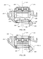
- FIG. 3 is an enlarged cross-sectional view of an example engagement between an example seat ring and an example valve body that may be used to implement the example fluid valve of FIGS. 2A and 2B .
- FIG. 4 is an enlarged cross-sectional view of another example engagement between an example seat ring and an example valve body that may be used to implement the example fluid valve of FIGS. 2A and 2B .
- the example apparatus and methods to align a seat ring in a valve described herein substantially eliminate leakage caused by misalignment of valve components.
- many known seat ring and valve body configurations utilize a seat ring that is engaged with the valve body via mating shoulders or other similar rectilinear surfaces. Such known mating surfaces are not typically capable of maintaining a sealed engagement between the seat ring and the valve body and, at the same time, compensating for misalignment between a movable control member (e.g., a plug) and a sealing surface of the seat ring.
- a movable control member e.g., a plug
- the seal between the seat ring and the valve body may be compromised.
- the movable control member may not be able to achieve tight shut off against the sealing surface of the seat ring.
- the example apparatus and methods described herein use curved (e.g., spherical, conical, elliptical, etc.) mating surfaces between the seat ring and the valve body to enable the seat ring to move relative to the valve body while maintaining a sealed engagement with the valve body.
- the mating surfaces are curved so that during assembly of a valve any misalignment (e.g., due to manufacturing tolerances) between the guide or cage, the movable control member (e.g., a plug), and the valve body can be automatically compensated for by a movement of the seat ring relative to the valve body.
- FIG. 1 illustrates an example of a known fluid valve 100, which includes a valve body 102, trim 104, and a bonnet 106.
- the trim 104 includes a plurality of components that vary the flow of the fluid through the valve 100.
- the trim 104 includes a seat ring 108, a guide 110, a control member 112, and a stem 114.
- the valve 100 and, thus, the trim 104 may include additional components (e.g., gaskets, packing flanges, springs, etc.).
- additional components e.g., gaskets, packing flanges, springs, etc.
- the valve body 102 is a housing or casing configured to facilitate the flow of a fluid from an inlet 116 through the valve 100 to an outlet 117.
- the valve body 102 supports or holds the trim 104 and, more particularly, includes seating surfaces for various valve components.
- an internal surface 118 of the valve body 102 may include a shoulder 119 to receive the seat ring 108.
- the characteristics (e.g., dimensional deviations from design values) of the internal surface 118 and the shoulder 119 may determine whether the valve components (e.g., the seat ring 108, the guide 110, the control member 112, etc.) are properly aligned.
- the trim 104 includes an assembly ofcomponents (e.g., the seat ring 108, the guide 110, the control member 112, and the stem 114) that cooperate to regulate the amount of fluid allowed to pass through the valve 100.
- the seat ring 108 is engaged with the shoulder 119, which is machined or shaped to include a planar surface to receive the seat ring 108.
- fluid flowing in the direction indicated by an arrow 120 in FIG. 1
- the control member 112 engages a sealing surface 122 of the seat ring 108, thereby preventing the flow of fluid through the valve 100.
- the control member 112 may be positioned between a fully open and a fully closed position to achieve a desired fluid flow through the valve 100.
- the guide 110 engages the seat ring 108 and surrounds a cavity 123 in which the control member 112 is disposed.
- the guide 110 facilitates the movement and alignment of the control member 112 and may be configured to include apertures or grooves to provide certain flow and/or control characteristics (e.g., dead band, gain, capacity, etc.) by modifying the configuration, profile, or shape of an orifice 124 through which the fluid flows.
- valves In general, accurate alignment ofthe valve components described above minimizes or substantially eliminates leakage through the valve 100 (i.e., enables tight shut off).
- many known valves can exhibit misalignment of certain valve components caused by, for example, manufacturing tolerances.
- the seat ring 108 may not be correctly received by the internal surface 118 and/or the shoulder 119 ofthe valve body 102.
- the internal surface 118 and/or the shoulder 119 of the valve body 102 may be dimensioned or shaped inaccurately such that the seat ring 108 cannot properly engage the internal surface 118 and/or the shoulder 119.
- one side or portion of the seat ring 108 may be skewed or tilted causing a non-uniform load to be experienced along the sealing surface 122 of the seat ring 108. Because the remainder of the trim 104 components (i.e., the guide 110, the control member 112, and the stem 114) are either directly or indirectly coupled to the seat ring 108, any misalignment of the seat ring 108 relative to the valve body 102 may be propagated to the guide 110 as well as other valve components, thereby preventing the movable control member or plug 112 from forming a tight seal against the sealing surface 122.
- FIG. 2A is a cross-sectional view of a portion of a partially assembled example fluid valve 200.
- a seat ring 202 is disposed in (e.g., inserted into) a valve body 204 to encompass a flow path within the valve 200.
- the seat ring 202 may be, for example, a cylindrical member having an aperture 206 through which the fluid may flow and a sealing surface 207.
- a movable control member 208 e.g., a plug
- the movable control member 208 may be encased by and configured to move within in a guide 210 (e.g., a cage) having an aperture 212 to enable an alignment between the control member 208 and the seat ring 202.
- a guide 210 e.g., a cage
- the aperture 206 of the seat ring 202 and the aperture 212 of the guide 210 may be aligned by forcing the aperture 206, the aperture 212, and the movable control member 208 to be coaxially aligned to a centerline 214.
- the guide 210 may engage the seat ring 202 via, for example, complementary interlocking structures 216 and 218, which may be configured to maintain alignment between the seat ring 202 and the guide 210.
- complementary interlocking structures 216 and 218 may be configured to maintain alignment between the seat ring 202 and the guide 210.
- the interlocking structure 218 on the seat ring 202 is depicted as a shoulder and the interlocking structure 216 of the guide 210 is depicted as a raised circumferential surface.
- the guide 208 may be driven against (e.g., via a hand-press fit) the seat ring 202 to engage the complementary interlocking structures 216 and 218.
- the seat ring 202 may be misaligned or skewed relative to the valve body 204.
- one side 220 of the seat ring 202 may be tilted upwards relative to an opposing side 222 because a surface of the valve body 204 is imprecisely dimensioned or manufactured.
- such a defect may cause a misalignment that is propagated through the valve.
- the example valve 200 illustrated in FIG. 2A enables the seat ring 202 to experience a uniform load (i.e., a consistent or substantially constant or uniform contact force along the seat ring 202), thereby eliminating leakage caused by misalignment.
- the example valve 200 employs a plurality of curved or spherically-shaped surfaces that enable alignment corrections to be made automatically during assembly of the valve 200.
- the valve body 204 includes a curved or spherically-shaped internal surface 224 to engage a complementary curved or spherically-shaped surface (e.g., a surface opposite the sealing surface 207) 226 of the seat ring 202.
- the curved surface 226 may extend away from the aperture 206 to engage the curved internal surface 224 of the valve body 204.
- the surfaces 224 and 226 may have substantially similar radii of curvature as indicated by a curved line 228 in FIG. 2A .
- the radius of curvature of each of the surfaces 224 and 226 may depend or be selected based on the dimensions of other valve components (e.g., the diameter of the guide 210).
- the curvature of the surfaces 224 and 226 allows the seat ring 202 to automatically move, shift, or adjust relative to the valve body 204 into proper alignment with the guide 210 during assembly of the valve 200.
- the one side 220 of the seat ring 202 may be misaligned (e.g., tilted or positioned higher) relative to the opposing side 222 of the seat ring 202 when disposed in the valve body 204.
- the seat ring 202 may move into alignment with the guide 210 as the curved or spherically-shaped surfaces 224 and 226 move relative to one another.
- the alignment correction results from the higher load experienced by the skewed side 220, which forces the seat ring 202 to adjust its position to balance the load experienced along its sealing surface.
- the seat ring 202 in this example is movably engaged with the valve body 204 and can be aligned automatically during assembly of the valve 200, thereby minimizing or eliminating the leakage problems mentioned above.
- FIG. 2B illustrates the example valve 200 after assembly.
- the guide 210 which may or may not yet include the control member 208, engages the seat ring 202 within the valve body 204.
- any misalignment between the guide 210 and the seat ring 202 are eliminated upon engagement.
- the remainder of the valve components e.g., the control member 208, a stem, gaskets, seals, etc.
- a bonnet (not shown) or other suitable securing structure may then be installed to secure the engagements and, thus, the alignment between the components.
- control member 208 may then be moved (e.g., via an actuator coupled to a stem) to engage or disengage the seat ring 202, thereby inhibiting or allowing fluid to pass through the seat ring 202 and, thus, the valve 200.
- the alignment corrections provided by the curved surfaces 224 and 226 allow the control member 208 to make a uniform seal with the seat ring 202.
- valves described herein may include a seat ring having a seal to provide a tight seal between the seat ring and a valve body.
- FIG. 3 is an enlarged cross-sectional view of a portion of such configuration within a valve 300.
- the valve 300 includes a seal 302 disposed about a circumference of a curved surface 304 of a seat ring 306 to engage a curved surface 308 of a valve body 310.
- the seat ring 306 may include a recess 312 (e.g., an annular groove positioned around an aperture of the seat ring 306) to receive the seal 302.
- the seal 302 may be, for example, configured as a seal bead or an o-ring. However, alternative profiles (e.g., a rectangular profile and/or a sealing engagement spaced around the seat ring 306) may be used to achieve a similar mechanical coupling.
- the seal 302 may be disposed in the recess 312 and constructed tc make a sealing engagement with the curved surface 308 of tne valve body 310. Additionally or alternatively, the curved surface 308 of the valve body 310 may include a groove or channel to receive the seal 302.
- the valve 300 may include a press-fit seal, thereby allowing the seat ring 306 to move about the curved surface 308 of the valve body 310, align itself with one or more valve components (e.g., the guide 210 of FIG. 2A ), and maintain the alignment of the valve components via the seal 302.
- a press-fit seal thereby allowing the seat ring 306 to move about the curved surface 308 of the valve body 310, align itself with one or more valve components (e.g., the guide 210 of FIG. 2A ), and maintain the alignment of the valve components via the seal 302.
- the seal 302 may be, but not necessarily, made of an elastomeric material and may further include fabric or other reinforcing layers to provide a desired stiffness, strength, life cycle, etc. However, in other applications, the seal 302 may be constructed of a composite material or a metal material to withstand higher temperature applications.
- an example valve 400 utilizes a metal-to-metal contact to maintain a sealed engagement between a seat ring 402 and a valve body 404.
- the valve 400 includes a circumferential protrusion (e.g., a bead) 406 extending from a curved surface 408 of the seat ring 402.
- the circumferential protrusion 406 may be configured to create a groove or indentation (not shown) on an internal surface 410 of the valve body 404.
- the protrusion 406 may create an indentation when a substantial force is applied to the seat ring 402.
- the seat ring 402 may be inserted into the valve body 404, after which a guide (not shown) may engage the seat ring 402 (similar to the process described above in connection with FIG. 2B ).
- a downward force may be applied to the components (i.e., the seat ring 402 via the guide), thereby causing the protrusion 406 to be driven to indent or embed itself in the surface 410 of the valve body 404.
- the protrusion 406, disposed within the newly formed indentation may then maintain the position of the seat ring 402 within the valve body 404 (i.e., creating a mechanically secured engagement similar to the seal described above in connection with FIG. 3 ). Additionally or alternatively, the force that creates the indentation may be applied at different stages ofthe valve assembly. As another example, securing (e.g., tightening fasteners) a bonnet (not shown) after the internal valve components (e.g., a control member, a guide, a stem, gaskets, etc.) are assembled may cause the protrusion 406 to create an indentation.
- Other example valves may include more than one protrusion to maintain the engagement between a seat ring and a valve body.
- a protrusion may be disposed on an internal surface (e.g., the internal surface 410 of FIG. 4 ) of a valve body (e.g., the valve body 404 of FIG. 4 ).
- the protrusion extending from the valve body may create an indentation on the surface of a seat ring (e.g., the seat ring 402 of FIG. 4 ) in response to an applied force, thereby facilitating an alignment similar to the operation of the example valve 400 of FIG. 4 .
Landscapes
- Engineering & Computer Science (AREA)
- General Engineering & Computer Science (AREA)
- Mechanical Engineering (AREA)
- Lift Valve (AREA)
- Automatic Assembly (AREA)
- Feeding And Controlling Fuel (AREA)
- Valve Housings (AREA)
Applications Claiming Priority (2)
| Application Number | Priority Date | Filing Date | Title |
|---|---|---|---|
| US11/778,410 US7954788B2 (en) | 2007-07-16 | 2007-07-16 | Methods and apparatus to align a seat ring in a valve |
| PCT/US2008/069846 WO2009012168A1 (en) | 2007-07-16 | 2008-07-11 | Methods and apparatus to align a seat ring in a valve |
Publications (2)
| Publication Number | Publication Date |
|---|---|
| EP2171321A1 EP2171321A1 (en) | 2010-04-07 |
| EP2171321B1 true EP2171321B1 (en) | 2013-11-06 |
Family
ID=39791677
Family Applications (1)
| Application Number | Title | Priority Date | Filing Date |
|---|---|---|---|
| EP20080781727 Active EP2171321B1 (en) | 2007-07-16 | 2008-07-11 | Methods and apparatus to align a seat ring in a valve |
Country Status (10)
| Country | Link |
|---|---|
| US (2) | US7954788B2 (enExample) |
| EP (1) | EP2171321B1 (enExample) |
| JP (1) | JP5389796B2 (enExample) |
| CN (1) | CN101688613B (enExample) |
| AU (1) | AU2008276194B2 (enExample) |
| BR (1) | BRPI0814303A2 (enExample) |
| CA (1) | CA2694746C (enExample) |
| NO (1) | NO339476B1 (enExample) |
| RU (1) | RU2477403C2 (enExample) |
| WO (1) | WO2009012168A1 (enExample) |
Families Citing this family (16)
| Publication number | Priority date | Publication date | Assignee | Title |
|---|---|---|---|---|
| CA2758970C (en) * | 2009-04-27 | 2016-02-16 | Emerson Process Management Regulator Technologies, Inc. | Self-aligning spring seat for fluid regulator and fluid regulator comprising self-aligning spring seat |
| US8714560B2 (en) * | 2009-04-28 | 2014-05-06 | Fisher Controls International Llc | Bidirectional seal assembly for use with valves |
| JP5525858B2 (ja) * | 2010-02-26 | 2014-06-18 | 株式会社フジキン | ボール弁 |
| JP5701384B2 (ja) * | 2010-07-30 | 2015-04-15 | フィッシャー コントロールズ インターナショナル リミテッド ライアビリティー カンパニー | 流体バルブと共に使用するためのバルブシート装置 |
| FR2970055A1 (fr) * | 2010-12-30 | 2012-07-06 | Michel Emin | Dispositif d'etancheite par siege-annulaire |
| CN103671938B (zh) * | 2012-09-21 | 2018-02-13 | 艾默生过程管理调节技术公司 | 自对准阀口 |
| US9267604B2 (en) | 2013-03-14 | 2016-02-23 | Fisher Controls International Llc | Valve seat apparatus for use with fluid valves |
| US9297469B2 (en) | 2013-03-14 | 2016-03-29 | Fisher Controls International Llc | Valve seat assemblies |
| US9746095B2 (en) | 2013-07-17 | 2017-08-29 | Fisher Controls International Llc | Apparatus to attach a fluid valve bonnet |
| CN104315169A (zh) * | 2014-11-18 | 2015-01-28 | 自贡自高阀门有限公司 | 一种快速定位安装节流截止放空阀阀瓣组件 |
| RU2641179C2 (ru) * | 2015-09-29 | 2018-01-16 | Общество с ограниченной ответственностью Фирма "Саратовгазприборавтоматика" (ООО Фирма "СГПА") | Клапан регулирующий |
| US20170123439A1 (en) * | 2015-10-30 | 2017-05-04 | Mekong Investments Limited | Regulators and Portable Power Systems |
| RU171255U1 (ru) * | 2016-09-13 | 2017-05-25 | Общество с ограниченной ответственностью Научно-производственная фирма "МКТ-АСДМ" | Узел затвора клиновой задвижки |
| US10851898B2 (en) * | 2016-09-29 | 2020-12-01 | Hitachi Metals, Ltd. | Flow control valve and mass flow controller using the same |
| US20200042021A1 (en) * | 2017-02-27 | 2020-02-06 | Bhushan Somani | Systems And Methods For Calibrating And Tuning A Mass Flow Controller |
| US11090713B2 (en) * | 2017-09-29 | 2021-08-17 | Fisher Controls International Llc | Bi-metal valve body casting and method of making same |
Family Cites Families (28)
| Publication number | Priority date | Publication date | Assignee | Title |
|---|---|---|---|---|
| GB414518A (en) | 1933-08-14 | 1934-08-09 | James William Brindley | Improvements in valves |
| GB631750A (en) | 1947-02-24 | 1949-11-09 | Charles Gordon Morley | Improvements in or relating to fuel-control valves |
| US2969218A (en) * | 1956-06-22 | 1961-01-24 | Bastian Blessing Co | Valve |
| US3174718A (en) * | 1961-11-17 | 1965-03-23 | Manning Maxwell & Moore Inc | Valve with improved head seal |
| US3362680A (en) * | 1962-10-18 | 1968-01-09 | Robert C. Weiss | Valve seat |
| US3489158A (en) * | 1966-11-16 | 1970-01-13 | Gen Electric Canada | Tube closure ball valve |
| US3648718A (en) * | 1970-06-01 | 1972-03-14 | Foxboro Co | Valve structure |
| US3762685A (en) * | 1971-12-09 | 1973-10-02 | Foxboro Co | Stem guided valve with cage assembly |
| US3892384A (en) * | 1974-04-12 | 1975-07-01 | Honeywell Inc | Double seated cage valve with flexible plug seat |
| US4064904A (en) * | 1976-04-30 | 1977-12-27 | Price Pfister Brass Mfg. Co. | Washerless cartridge valve for faucets |
| JPS54124222U (enExample) * | 1978-02-21 | 1979-08-30 | ||
| JPS54124222A (en) * | 1978-03-20 | 1979-09-27 | Hitachi Ltd | Three-leg winding iron core manufacturing method |
| US4542879A (en) * | 1981-11-27 | 1985-09-24 | Marbor Engineering Associates | Valve ring arrangements in metallic valves, control valves, condensate removal devices, and other means for the prevention of leakages due to corrosion |
| FR2570790B1 (fr) * | 1984-09-26 | 1987-03-20 | Sereg Soc | Robinet a soupape a siege demontable et a maintenance rapide |
| SU1620755A1 (ru) * | 1988-05-30 | 1991-01-15 | Производственное Объединение "Ждановтяжмаш" | Запорное устройство |
| JPH03154481A (ja) * | 1989-11-10 | 1991-07-02 | Sony Corp | 撮像素子の支持装置 |
| JPH0462469U (enExample) * | 1990-10-02 | 1992-05-28 | ||
| JPH0497110U (enExample) * | 1991-01-21 | 1992-08-21 | ||
| JPH0653816U (ja) * | 1992-12-28 | 1994-07-22 | 宣行 杉村 | 球面座金 |
| US6003551A (en) * | 1995-07-14 | 1999-12-21 | Fisher Controls International, Inc. | Bidirectional fluid control valve |
| JP3814731B2 (ja) * | 1997-05-23 | 2006-08-30 | 日立バルブ株式会社 | バルブ |
| GB2332261A (en) | 1997-12-06 | 1999-06-16 | Wabco Automotive Uk | Valve with rigid annular seal |
| RU2153115C2 (ru) * | 1998-06-09 | 2000-07-20 | Акционерная компания "Корвет" | Клиновая задвижка с самоустанавливающимися седлами |
| JP4034529B2 (ja) * | 2000-07-28 | 2008-01-16 | 株式会社山武 | 単座形弁装置 |
| US6698449B2 (en) * | 2001-11-15 | 2004-03-02 | Fisher Controls International Llc | Replaceable valve seat ring with enhanced flow design |
| TW572164U (en) * | 2002-12-06 | 2004-01-11 | Ind Tech Res Inst | Diaphragm valve |
| JP2006523810A (ja) * | 2003-04-14 | 2006-10-19 | スワゲロック カンパニー | ダイヤフラムバルブシート |
| JP4440798B2 (ja) * | 2005-02-10 | 2010-03-24 | 株式会社コガネイ | ダイアフラムバルブ |
-
2007
- 2007-07-16 US US11/778,410 patent/US7954788B2/en active Active
-
2008
- 2008-07-11 WO PCT/US2008/069846 patent/WO2009012168A1/en not_active Ceased
- 2008-07-11 RU RU2010103525/06A patent/RU2477403C2/ru active
- 2008-07-11 JP JP2010517088A patent/JP5389796B2/ja not_active Expired - Fee Related
- 2008-07-11 AU AU2008276194A patent/AU2008276194B2/en active Active
- 2008-07-11 CN CN2008800239782A patent/CN101688613B/zh active Active
- 2008-07-11 EP EP20080781727 patent/EP2171321B1/en active Active
- 2008-07-11 BR BRPI0814303 patent/BRPI0814303A2/pt active Search and Examination
- 2008-07-11 CA CA 2694746 patent/CA2694746C/en active Active
-
2010
- 2010-01-08 NO NO20100014A patent/NO339476B1/no not_active IP Right Cessation
-
2011
- 2011-04-30 US US13/098,425 patent/US8991786B2/en active Active
Also Published As
| Publication number | Publication date |
|---|---|
| US8991786B2 (en) | 2015-03-31 |
| AU2008276194A1 (en) | 2009-01-22 |
| CA2694746C (en) | 2014-09-30 |
| US20110204275A1 (en) | 2011-08-25 |
| CA2694746A1 (en) | 2009-01-22 |
| EP2171321A1 (en) | 2010-04-07 |
| US7954788B2 (en) | 2011-06-07 |
| NO20100014L (no) | 2010-02-15 |
| AU2008276194B2 (en) | 2015-06-04 |
| NO339476B1 (no) | 2016-12-12 |
| CN101688613B (zh) | 2012-05-30 |
| CN101688613A (zh) | 2010-03-31 |
| JP2010533831A (ja) | 2010-10-28 |
| US20090020720A1 (en) | 2009-01-22 |
| JP5389796B2 (ja) | 2014-01-15 |
| WO2009012168A1 (en) | 2009-01-22 |
| RU2010103525A (ru) | 2011-08-27 |
| BRPI0814303A2 (pt) | 2015-02-03 |
| RU2477403C2 (ru) | 2013-03-10 |
Similar Documents
| Publication | Publication Date | Title |
|---|---|---|
| EP2171321B1 (en) | Methods and apparatus to align a seat ring in a valve | |
| US10221961B2 (en) | Anti-rotation assemblies for use with fluid valves | |
| RU2532063C2 (ru) | Затворный механизм для использования в клапанах | |
| US6851658B2 (en) | Control valve trim and bore seal | |
| EP2236876B1 (en) | Piloted poppet valve | |
| US8066258B2 (en) | Valve seat apparatus for use with fluid valves | |
| EP2440819B1 (en) | Fluid valves having dynamic valve trim joints | |
| CN111911634A (zh) | 包括在阀盖与阀笼之间具有相对移动的阀内件的控制阀 | |
| US7077384B2 (en) | Integrated post-guided seat ring assembly | |
| JPH06249347A (ja) | 弁装置 |
Legal Events
| Date | Code | Title | Description |
|---|---|---|---|
| PUAI | Public reference made under article 153(3) epc to a published international application that has entered the european phase |
Free format text: ORIGINAL CODE: 0009012 |
|
| 17P | Request for examination filed |
Effective date: 20100129 |
|
| AK | Designated contracting states |
Kind code of ref document: A1 Designated state(s): AT BE BG CH CY CZ DE DK EE ES FI FR GB GR HR HU IE IS IT LI LT LU LV MC MT NL NO PL PT RO SE SI SK TR |
|
| AX | Request for extension of the european patent |
Extension state: AL BA MK RS |
|
| RIN1 | Information on inventor provided before grant (corrected) |
Inventor name: WESTWATER, DAVID, J. Inventor name: DAVIES, LONNIE, OSCAR, JR. |
|
| 17Q | First examination report despatched |
Effective date: 20100716 |
|
| DAX | Request for extension of the european patent (deleted) | ||
| GRAP | Despatch of communication of intention to grant a patent |
Free format text: ORIGINAL CODE: EPIDOSNIGR1 |
|
| INTG | Intention to grant announced |
Effective date: 20130411 |
|
| GRAS | Grant fee paid |
Free format text: ORIGINAL CODE: EPIDOSNIGR3 |
|
| GRAP | Despatch of communication of intention to grant a patent |
Free format text: ORIGINAL CODE: EPIDOSNIGR1 |
|
| INTG | Intention to grant announced |
Effective date: 20130905 |
|
| GRAA | (expected) grant |
Free format text: ORIGINAL CODE: 0009210 |
|
| AK | Designated contracting states |
Kind code of ref document: B1 Designated state(s): AT BE BG CH CY CZ DE DK EE ES FI FR GB GR HR HU IE IS IT LI LT LU LV MC MT NL NO PL PT RO SE SI SK TR |
|
| REG | Reference to a national code |
Ref country code: GB Ref legal event code: FG4D |
|
| REG | Reference to a national code |
Ref country code: CH Ref legal event code: EP |
|
| REG | Reference to a national code |
Ref country code: AT Ref legal event code: REF Ref document number: 639728 Country of ref document: AT Kind code of ref document: T Effective date: 20131215 |
|
| REG | Reference to a national code |
Ref country code: IE Ref legal event code: FG4D |
|
| REG | Reference to a national code |
Ref country code: DE Ref legal event code: R096 Ref document number: 602008028587 Country of ref document: DE Effective date: 20140102 |
|
| REG | Reference to a national code |
Ref country code: SE Ref legal event code: TRGR |
|
| REG | Reference to a national code |
Ref country code: NL Ref legal event code: VDEP Effective date: 20131106 |
|
| REG | Reference to a national code |
Ref country code: AT Ref legal event code: MK05 Ref document number: 639728 Country of ref document: AT Kind code of ref document: T Effective date: 20131106 |
|
| REG | Reference to a national code |
Ref country code: LT Ref legal event code: MG4D |
|
| PG25 | Lapsed in a contracting state [announced via postgrant information from national office to epo] |
Ref country code: LT Free format text: LAPSE BECAUSE OF FAILURE TO SUBMIT A TRANSLATION OF THE DESCRIPTION OR TO PAY THE FEE WITHIN THE PRESCRIBED TIME-LIMIT Effective date: 20131106 Ref country code: NO Free format text: LAPSE BECAUSE OF FAILURE TO SUBMIT A TRANSLATION OF THE DESCRIPTION OR TO PAY THE FEE WITHIN THE PRESCRIBED TIME-LIMIT Effective date: 20140206 Ref country code: HR Free format text: LAPSE BECAUSE OF FAILURE TO SUBMIT A TRANSLATION OF THE DESCRIPTION OR TO PAY THE FEE WITHIN THE PRESCRIBED TIME-LIMIT Effective date: 20131106 Ref country code: IS Free format text: LAPSE BECAUSE OF FAILURE TO SUBMIT A TRANSLATION OF THE DESCRIPTION OR TO PAY THE FEE WITHIN THE PRESCRIBED TIME-LIMIT Effective date: 20140306 Ref country code: NL Free format text: LAPSE BECAUSE OF FAILURE TO SUBMIT A TRANSLATION OF THE DESCRIPTION OR TO PAY THE FEE WITHIN THE PRESCRIBED TIME-LIMIT Effective date: 20131106 |
|
| PG25 | Lapsed in a contracting state [announced via postgrant information from national office to epo] |
Ref country code: AT Free format text: LAPSE BECAUSE OF FAILURE TO SUBMIT A TRANSLATION OF THE DESCRIPTION OR TO PAY THE FEE WITHIN THE PRESCRIBED TIME-LIMIT Effective date: 20131106 Ref country code: ES Free format text: LAPSE BECAUSE OF FAILURE TO SUBMIT A TRANSLATION OF THE DESCRIPTION OR TO PAY THE FEE WITHIN THE PRESCRIBED TIME-LIMIT Effective date: 20131106 Ref country code: LV Free format text: LAPSE BECAUSE OF FAILURE TO SUBMIT A TRANSLATION OF THE DESCRIPTION OR TO PAY THE FEE WITHIN THE PRESCRIBED TIME-LIMIT Effective date: 20131106 Ref country code: BE Free format text: LAPSE BECAUSE OF FAILURE TO SUBMIT A TRANSLATION OF THE DESCRIPTION OR TO PAY THE FEE WITHIN THE PRESCRIBED TIME-LIMIT Effective date: 20131106 |
|
| PG25 | Lapsed in a contracting state [announced via postgrant information from national office to epo] |
Ref country code: PT Free format text: LAPSE BECAUSE OF FAILURE TO SUBMIT A TRANSLATION OF THE DESCRIPTION OR TO PAY THE FEE WITHIN THE PRESCRIBED TIME-LIMIT Effective date: 20140306 |
|
| PG25 | Lapsed in a contracting state [announced via postgrant information from national office to epo] |
Ref country code: EE Free format text: LAPSE BECAUSE OF FAILURE TO SUBMIT A TRANSLATION OF THE DESCRIPTION OR TO PAY THE FEE WITHIN THE PRESCRIBED TIME-LIMIT Effective date: 20131106 |
|
| REG | Reference to a national code |
Ref country code: DE Ref legal event code: R097 Ref document number: 602008028587 Country of ref document: DE |
|
| PG25 | Lapsed in a contracting state [announced via postgrant information from national office to epo] |
Ref country code: SK Free format text: LAPSE BECAUSE OF FAILURE TO SUBMIT A TRANSLATION OF THE DESCRIPTION OR TO PAY THE FEE WITHIN THE PRESCRIBED TIME-LIMIT Effective date: 20131106 Ref country code: RO Free format text: LAPSE BECAUSE OF FAILURE TO SUBMIT A TRANSLATION OF THE DESCRIPTION OR TO PAY THE FEE WITHIN THE PRESCRIBED TIME-LIMIT Effective date: 20131106 Ref country code: PL Free format text: LAPSE BECAUSE OF FAILURE TO SUBMIT A TRANSLATION OF THE DESCRIPTION OR TO PAY THE FEE WITHIN THE PRESCRIBED TIME-LIMIT Effective date: 20131106 Ref country code: IT Free format text: LAPSE BECAUSE OF FAILURE TO SUBMIT A TRANSLATION OF THE DESCRIPTION OR TO PAY THE FEE WITHIN THE PRESCRIBED TIME-LIMIT Effective date: 20131106 Ref country code: CZ Free format text: LAPSE BECAUSE OF FAILURE TO SUBMIT A TRANSLATION OF THE DESCRIPTION OR TO PAY THE FEE WITHIN THE PRESCRIBED TIME-LIMIT Effective date: 20131106 |
|
| PLBE | No opposition filed within time limit |
Free format text: ORIGINAL CODE: 0009261 |
|
| STAA | Information on the status of an ep patent application or granted ep patent |
Free format text: STATUS: NO OPPOSITION FILED WITHIN TIME LIMIT |
|
| PG25 | Lapsed in a contracting state [announced via postgrant information from national office to epo] |
Ref country code: DK Free format text: LAPSE BECAUSE OF FAILURE TO SUBMIT A TRANSLATION OF THE DESCRIPTION OR TO PAY THE FEE WITHIN THE PRESCRIBED TIME-LIMIT Effective date: 20131106 |
|
| 26N | No opposition filed |
Effective date: 20140807 |
|
| REG | Reference to a national code |
Ref country code: DE Ref legal event code: R097 Ref document number: 602008028587 Country of ref document: DE Effective date: 20140807 |
|
| PG25 | Lapsed in a contracting state [announced via postgrant information from national office to epo] |
Ref country code: SI Free format text: LAPSE BECAUSE OF FAILURE TO SUBMIT A TRANSLATION OF THE DESCRIPTION OR TO PAY THE FEE WITHIN THE PRESCRIBED TIME-LIMIT Effective date: 20131106 Ref country code: LU Free format text: LAPSE BECAUSE OF FAILURE TO SUBMIT A TRANSLATION OF THE DESCRIPTION OR TO PAY THE FEE WITHIN THE PRESCRIBED TIME-LIMIT Effective date: 20140711 |
|
| REG | Reference to a national code |
Ref country code: CH Ref legal event code: PL |
|
| REG | Reference to a national code |
Ref country code: IE Ref legal event code: MM4A |
|
| PG25 | Lapsed in a contracting state [announced via postgrant information from national office to epo] |
Ref country code: CH Free format text: LAPSE BECAUSE OF NON-PAYMENT OF DUE FEES Effective date: 20140731 Ref country code: LI Free format text: LAPSE BECAUSE OF NON-PAYMENT OF DUE FEES Effective date: 20140731 |
|
| PG25 | Lapsed in a contracting state [announced via postgrant information from national office to epo] |
Ref country code: IE Free format text: LAPSE BECAUSE OF NON-PAYMENT OF DUE FEES Effective date: 20140711 |
|
| PG25 | Lapsed in a contracting state [announced via postgrant information from national office to epo] |
Ref country code: MC Free format text: LAPSE BECAUSE OF FAILURE TO SUBMIT A TRANSLATION OF THE DESCRIPTION OR TO PAY THE FEE WITHIN THE PRESCRIBED TIME-LIMIT Effective date: 20131106 |
|
| PG25 | Lapsed in a contracting state [announced via postgrant information from national office to epo] |
Ref country code: BG Free format text: LAPSE BECAUSE OF FAILURE TO SUBMIT A TRANSLATION OF THE DESCRIPTION OR TO PAY THE FEE WITHIN THE PRESCRIBED TIME-LIMIT Effective date: 20131106 |
|
| PG25 | Lapsed in a contracting state [announced via postgrant information from national office to epo] |
Ref country code: MT Free format text: LAPSE BECAUSE OF FAILURE TO SUBMIT A TRANSLATION OF THE DESCRIPTION OR TO PAY THE FEE WITHIN THE PRESCRIBED TIME-LIMIT Effective date: 20131106 Ref country code: GR Free format text: LAPSE BECAUSE OF FAILURE TO SUBMIT A TRANSLATION OF THE DESCRIPTION OR TO PAY THE FEE WITHIN THE PRESCRIBED TIME-LIMIT Effective date: 20140207 Ref country code: CY Free format text: LAPSE BECAUSE OF FAILURE TO SUBMIT A TRANSLATION OF THE DESCRIPTION OR TO PAY THE FEE WITHIN THE PRESCRIBED TIME-LIMIT Effective date: 20131106 |
|
| REG | Reference to a national code |
Ref country code: FR Ref legal event code: PLFP Year of fee payment: 9 |
|
| PG25 | Lapsed in a contracting state [announced via postgrant information from national office to epo] |
Ref country code: TR Free format text: LAPSE BECAUSE OF FAILURE TO SUBMIT A TRANSLATION OF THE DESCRIPTION OR TO PAY THE FEE WITHIN THE PRESCRIBED TIME-LIMIT Effective date: 20131106 Ref country code: HU Free format text: LAPSE BECAUSE OF FAILURE TO SUBMIT A TRANSLATION OF THE DESCRIPTION OR TO PAY THE FEE WITHIN THE PRESCRIBED TIME-LIMIT; INVALID AB INITIO Effective date: 20080711 |
|
| REG | Reference to a national code |
Ref country code: FR Ref legal event code: PLFP Year of fee payment: 10 |
|
| REG | Reference to a national code |
Ref country code: FR Ref legal event code: PLFP Year of fee payment: 11 |
|
| P01 | Opt-out of the competence of the unified patent court (upc) registered |
Effective date: 20230526 |
|
| PGFP | Annual fee paid to national office [announced via postgrant information from national office to epo] |
Ref country code: FR Payment date: 20230621 Year of fee payment: 16 |
|
| PGFP | Annual fee paid to national office [announced via postgrant information from national office to epo] |
Ref country code: FI Payment date: 20230622 Year of fee payment: 16 |
|
| PG25 | Lapsed in a contracting state [announced via postgrant information from national office to epo] |
Ref country code: FI Free format text: LAPSE BECAUSE OF NON-PAYMENT OF DUE FEES Effective date: 20240711 |
|
| PG25 | Lapsed in a contracting state [announced via postgrant information from national office to epo] |
Ref country code: FR Free format text: LAPSE BECAUSE OF NON-PAYMENT OF DUE FEES Effective date: 20240731 |
|
| PGFP | Annual fee paid to national office [announced via postgrant information from national office to epo] |
Ref country code: GB Payment date: 20250619 Year of fee payment: 18 |
|
| PGFP | Annual fee paid to national office [announced via postgrant information from national office to epo] |
Ref country code: SE Payment date: 20250619 Year of fee payment: 18 |
|
| PGFP | Annual fee paid to national office [announced via postgrant information from national office to epo] |
Ref country code: DE Payment date: 20250620 Year of fee payment: 18 |