EP2440819B1 - Fluid valves having dynamic valve trim joints - Google Patents
Fluid valves having dynamic valve trim joints Download PDFInfo
- Publication number
- EP2440819B1 EP2440819B1 EP10717433.6A EP10717433A EP2440819B1 EP 2440819 B1 EP2440819 B1 EP 2440819B1 EP 10717433 A EP10717433 A EP 10717433A EP 2440819 B1 EP2440819 B1 EP 2440819B1
- Authority
- EP
- European Patent Office
- Prior art keywords
- cage
- bonnet
- diameter
- projections
- cage retainer
- Prior art date
- Legal status (The legal status is an assumption and is not a legal conclusion. Google has not performed a legal analysis and makes no representation as to the accuracy of the status listed.)
- Active
Links
Images


Classifications
-
- F—MECHANICAL ENGINEERING; LIGHTING; HEATING; WEAPONS; BLASTING
- F16—ENGINEERING ELEMENTS AND UNITS; GENERAL MEASURES FOR PRODUCING AND MAINTAINING EFFECTIVE FUNCTIONING OF MACHINES OR INSTALLATIONS; THERMAL INSULATION IN GENERAL
- F16K—VALVES; TAPS; COCKS; ACTUATING-FLOATS; DEVICES FOR VENTING OR AERATING
- F16K25/00—Details relating to contact between valve members and seat
- F16K25/04—Arrangements for preventing erosion, not otherwise provided for
-
- F—MECHANICAL ENGINEERING; LIGHTING; HEATING; WEAPONS; BLASTING
- F16—ENGINEERING ELEMENTS AND UNITS; GENERAL MEASURES FOR PRODUCING AND MAINTAINING EFFECTIVE FUNCTIONING OF MACHINES OR INSTALLATIONS; THERMAL INSULATION IN GENERAL
- F16K—VALVES; TAPS; COCKS; ACTUATING-FLOATS; DEVICES FOR VENTING OR AERATING
- F16K3/00—Gate valves or sliding valves, i.e. cut-off apparatus with closing members having a sliding movement along the seat for opening and closing
- F16K3/22—Gate valves or sliding valves, i.e. cut-off apparatus with closing members having a sliding movement along the seat for opening and closing with sealing faces shaped as surfaces of solids of revolution
- F16K3/24—Gate valves or sliding valves, i.e. cut-off apparatus with closing members having a sliding movement along the seat for opening and closing with sealing faces shaped as surfaces of solids of revolution with cylindrical valve members
- F16K3/246—Combination of a sliding valve and a lift valve
-
- F—MECHANICAL ENGINEERING; LIGHTING; HEATING; WEAPONS; BLASTING
- F16—ENGINEERING ELEMENTS AND UNITS; GENERAL MEASURES FOR PRODUCING AND MAINTAINING EFFECTIVE FUNCTIONING OF MACHINES OR INSTALLATIONS; THERMAL INSULATION IN GENERAL
- F16K—VALVES; TAPS; COCKS; ACTUATING-FLOATS; DEVICES FOR VENTING OR AERATING
- F16K47/00—Means in valves for absorbing fluid energy
- F16K47/08—Means in valves for absorbing fluid energy for decreasing pressure or noise level and having a throttling member separate from the closure member, e.g. screens, slots, labyrinths
-
- Y—GENERAL TAGGING OF NEW TECHNOLOGICAL DEVELOPMENTS; GENERAL TAGGING OF CROSS-SECTIONAL TECHNOLOGIES SPANNING OVER SEVERAL SECTIONS OF THE IPC; TECHNICAL SUBJECTS COVERED BY FORMER USPC CROSS-REFERENCE ART COLLECTIONS [XRACs] AND DIGESTS
- Y10—TECHNICAL SUBJECTS COVERED BY FORMER USPC
- Y10T—TECHNICAL SUBJECTS COVERED BY FORMER US CLASSIFICATION
- Y10T137/00—Fluid handling
- Y10T137/7504—Removable valve head and seat unit
- Y10T137/7668—Retained by bonnet or closure
-
- Y—GENERAL TAGGING OF NEW TECHNOLOGICAL DEVELOPMENTS; GENERAL TAGGING OF CROSS-SECTIONAL TECHNOLOGIES SPANNING OVER SEVERAL SECTIONS OF THE IPC; TECHNICAL SUBJECTS COVERED BY FORMER USPC CROSS-REFERENCE ART COLLECTIONS [XRACs] AND DIGESTS
- Y10—TECHNICAL SUBJECTS COVERED BY FORMER USPC
- Y10T—TECHNICAL SUBJECTS COVERED BY FORMER US CLASSIFICATION
- Y10T137/00—Fluid handling
- Y10T137/7722—Line condition change responsive valves
- Y10T137/7737—Thermal responsive
Definitions
- the present patent relates generally to fluid valves and, more particularly, to fluid valves having dynamic valve trim joints.
- Control valves are commonly used in process plants to control the flow of a fluid (e.g., a gas, a liquid, etc.) or any other substance through pipes and/or vessels to which they are connected.
- a control valve is typically composed of one or more inlets and outlets, and includes a flow control element or member (e.g., a valve gate, a piston, a valve plug, a closure member, etc.) that operates to control fluid flow through apertures that fluidly couple the inlet(s) to the outlet(s).
- a closure member is typically coupled to a valve bonnet that is mechanically coupled (e.g., bolted, clamped, threaded into, etc.) to the valve body.
- the closure member is configured to engage a sealing structure (e.g., a seat ring) that encompasses a flow path through the valve.
- different components of the control valve are made of different materials having different coefficients of thermal expansion. As such, in high temperature applications, the coefficients of thermal expansion of the materials from which the different control valve components are made have to be taken into account.
- Patent Document EP2042685 relates to a choke assembly, in particular to a choke assembly having a plug and cage type arrangement, and to the use of the choke assembly in the processing of fluid streams.
- the examples described herein relate to fluid valves having a dynamic joint between, for example, a cage retainer and a bonnet.
- a dynamic joint allows the cage retainer to move (e.g., slide) relative to the bonnet to accommodate and compensate for thermal expansion or contraction of the valve body, the cage retainer, the bonnet, the cage and/or other valve components.
- the examples described herein substantially reduce the amount of thermal expansion of the cage retainer by enabling the cage retainer to be made of a material (e.g., a steel material) that is similar to or the same as a material forming a bonnet coupled to the fluid valve.
- a cage coaxially aligned with and engaged to the cage retainer may engage a seat ring to maintain the position of the seat ring within the valve body, thereby eliminating the need to use fasteners to couple the seat ring to the valve body.
- Such an approach may decrease the amount of distortion imparted to the seat ring when coupling the seat ring to the valve body and simplifies the assembly and/or disassembly of the fluid valve.
- a plurality of projections made of a different material than the bonnet material and the cage retainer material are radially positioned around an exterior surface of the cage retainer.
- the plurality of projections act as a spacer between the exterior surface of the cage retainer and an inner surface of the bonnet, thereby preventing the exterior surface of the cage retainer from continuously engaging the inner surface of the bonnet.
- Preventing the exterior surface of the cage retainer from continuously engaging the inner surface of the bonnet substantially prevents the cage retainer and the bonnet from becoming fixed (e.g., corroded) together over time and, thus, a dynamic joint between these components may be maintained.
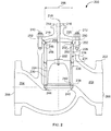
- FIG. 1 depicts a known fluid valve 100 that has a valve body 102 having a fluid flow passageway 104 between an inlet 106 and an outlet 108.
- a bonnet 110 is coupled to the valve body 102 via a plurality of fasteners 112 and includes a bore 114 to receive a stem 116.
- An end 118 of the stem 116 extends from the bonnet 110 and is operatively coupled to an actuator (not shown), and an opposite end 120 of the stem 116 is coupled to a closure member 122 (e.g., a valve plug).
- a closure member 122 e.g., a valve plug
- valve trim 124 is positioned between the inlet 106 and the outlet 108 to provide certain flow characteristics (e.g., to reduce noise and/or cavitation generated by the flow of fluid through the fluid valve 100).
- the valve trim 124 includes a hanging cage 126, the closure member 122 and the stem 116.
- the hanging cage 126 includes a flange 128 that is positioned in a circumferential groove 130 defined by the valve body 102 and is engaged by a portion 132 of the bonnet 110.
- the hanging cage 126 is typically made of a stainless steel material and the valve body 102 and the bonnet 110 are both typically made of a different steel material having a coefficient of thermal expansion different than the stainless steel material. As such, the hanging cage 126, the valve body 102 and/or the bonnet 110 may expand and/or contract at different rates and/or amounts as the fluid valve 100 is subjected to, for example, a thermal cycle.
- a gap 134 is provided between an end 136 of the hanging cage 126 and a seat ring 138 positioned at least partially within an aperture 140 of the valve body 102.
- the seat ring 138 is coupled or fixed to the valve body 102 via a plurality of fasteners 142 (e.g., thirty (30) fasteners).
- a spring loaded seal(s) and/or a spiral wound gasket 144 is positioned between the seat ring 138 and the valve body 102.
- the spring loaded seal(s) 144 exerts an opposing force against the seat ring 138 that, in some instances, may distort the seat ring 138.
- this distortion may prevent the closure member 122 from properly (e.g., sealingly) engaging the seat ring 138 and, thus, prevent the closure member 122 from properly controlling fluid flow through the fluid valve 100.
- the seat ring 138 may be machined while coupled to the valve body 102, which is typically a labor intensive and expensive process.
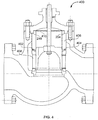
- FIG. 2 depicts an example fluid valve 200 that has a valve body 202 including a fluid flow passageway 204 between an inlet 206 and an outlet 208.
- a bonnet 210 is coupled to the valve body 202 via a plurality of fasteners 212 and includes a bore 214 to receive a stem 216.
- An end 218 of the stem 216 extends from a bonnet body 220 and is operatively coupled to an actuator (not shown), and an opposite end 222 of the stem 216 is coupled to a closure member 224 (e.g., a valve plug).
- a closure member 224 e.g., a valve plug
- valve trim 226 of the fluid valve 200 includes a cage retainer 228 (e.g., an upper cage retainer or guide), a cage 230, the closure member 224 and the stem 216.
- a cage retainer 228 e.g., an upper cage retainer or guide
- cage 230 e.g., the closure member 224 and the stem 216.
- an end 232 of the cage retainer 228 is positioned at least partially within the valve body 202 and adjacent the bonnet 210 and an opposing end 234 of the cage retainer 228 engages an end 236 of the cage 230 such that the cage retainer 228 and the cage 230 are coaxially aligned.
- the cage 230 is positioned within the valve body 202 such that opposing steps or shoulders 238 and 240 of the cage 230 and a seat 242 (e.g., a seat ring) engage and/or interlock to secure the seat 242 at least partially within an aperture 244 of the valve body 202.
- a seat 242 e.g., a seat ring
- the seat 242 may be more easily removed from and/or assembled within the example fluid valve 200 during, for example, routine maintenance.
- securing the seat 242 to the valve body 202 via the cage 230 and the cage retainer 228 as shown in FIG. 2 eliminates a gap (e.g., the gap 134 of FIG. 1 ), which enables a hanging cage (e.g., such as the hanging cage 126 of FIG. 1 ) to expand and/or contract at a different rate and/or amount than a valve body.
- a dynamic joint 252 is provided instead of providing a gap between the cage 230 and the seat 242 to accommodate thermal expansion/contraction of the cage 230, the cage retainer 228, the seat 242, the valve body 202 and/or any other valve components.
- the dynamic joint 252 allows the cage 230 and the cage retainer 228 to expand/contract (e.g., in response to thermal cycles) while enabling the cage 230 to remain in contact with the seat 242 to maintain the seat 242 in sealing engagement with the aperture 244.
- the example of FIG. 2 is also configured to reduce the total amount of thermal expansion/contraction of the cage 230 and the cage retainer 228 assembly.
- the cage retainer 228 may be made of a steel material and the cage 230 may be made of a stainless steel material, which typically expands at a faster rate and/or a greater amount than the steel material of the cage 230.
- the fluid valve 200 may be provided with the cage retainer 228 made of a first material (e.g., a steel material) that has a relatively lower coefficient of thermal expansion than a second material (e.g., a stainless steel material) forming the cage 230.
- Using a material having a relatively lower coefficient of thermal expansion to form the cage retainer 228 reduces the total amount of thermal expansion of the cage 230 and the cage retainer 228 assembly by approximately one half (1/2) as compared to a single-piece cage (not shown) made of a stainless steel material or an assembly in which the cage retainer 228 and the cage 230 are both made of a stainless steel material. Additionally, such an approach enables the cage 230 to be made of a substantially non-corrosive material (e.g., a stainless steel), which reduces the likelihood that the closure member 224 will become seized within the cage 230 and/or fail to engage the seat 242.
- a substantially non-corrosive material e.g., a stainless steel
- Providing the fluid valve 200 with the cage retainer 228 made of the first material having a relatively lower coefficient of thermal expansion than the second material forming the cage 230 reduces an amount of thermal expansion as compared to the alternatives described above.
- an outer or exterior surface 248 of the cage retainer 228 were to continuously engage an inner surface 250 of the bonnet 210, over time, corrosion may occur between the outer surface 248 of the cage retainer 228 and the inner surface 250 of the bonnet 210 because the cage retainer 228 and the bonnet 210 may be made of a similar or identical material (e.g., a steel material) having similar or identical coefficients of thermal expansion.
- Such corrosion may substantially fix the cage retainer 228 relative to the bonnet 210, thereby compromising the operation of the dynamic joint 252 and increasing the difficulty encountered when disassembling the valve trim 226 of the fluid valve 200.
- the cage retainer 228 becomes fixed (e.g., corroded) to the bonnet 210 the dynamic joint 252 becomes compromised and the cage retainer 228 may no longer be able to move relative to the bonnet 210 during thermal cycles.
- the cage retainer 228 and the cage 230 may fail to maintain the seat 242 in sealing engagement with the aperture 244 of the valve body 202 and/or the alignment of the valve trim 226 may be compromised, thereby affecting the performance of the fluid valve 200.
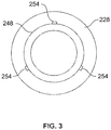
- the exterior surface 248 of the cage retainer 228 is provided with a plurality of projections 254 ( FIG. 3 ), each having a relatively small surface area, that are radially spaced about the exterior surface 248. While the example cage retainer 228 is depicted in FIG. 3 as including three projections 254, the example cage retainer 228 may include any number of projections 254 (e.g., 1, 2, 3, etc.) that are similarly or differently shaped.
- each of the projections 254 provides one or more contact points between the exterior surface 248 of the cage retainer 228 and the inner surface 250 of the bonnet 210, thereby enabling the dynamic joint 252 to be maintained between the cage retainer 228 and the bonnet 210.
- each of the projections 254 may be made of a third material such as, for example, a stellite alloy material, a cobalt alloy material, a non-corrosive material, etc., while the bonnet 210 and the cage retainer 228 may be made of the first material such as, for example, a steel material.
- the exterior surface 248 of the cage retainer 228 were to engage (e.g., continuously engage) the inner surface 250 of the bonnet 210, this interaction would enable the surfaces 248 and 250 to become corroded together.
- the exterior surface 248 may alternatively or additionally be provided with a coating of a non-corrosive material, such as chrome, that acts as a buffer between the exterior surface 248 and the inner surface 250 to maintain the dynamic joint 252.
- the example cage retainer 228 may not be provided with the projections 254.
- the seat 242 is positioned at least partially within the aperture 244 and the cage 230 is inserted into the valve body 202 to engage and/or interlock the opposing steps 238 and 240 of the cage 230 and the seat 242, respectively.
- the cage retainer 228 is then positioned in the valve body 202 such that the end 234 of the cage retainer 228 engages the opposing end 236 of the cage 230 and the other end 232 of the cage retainer 228 is positioned adjacent the bonnet 210.
- the bonnet 210 may then be aligned and coupled to the valve body 202 via the fasteners 212.
- a portion 262 of the bonnet 210 is positioned such that the inner surface 250 of the bonnet 210 surrounds the exterior surface 248 of the cage retainer 228 and the projections 254 are positioned between the surfaces 248 and 250.
- a bias element 258 e.g., a spring or seal
- the bias element 258 may react (e.g., expand or contract) in response to the relative position of the cage retainer 228 and/or the cage 230 within the valve body 202.
- the cage 230 may expand (e.g., elongate), thereby moving the cage retainer 228 and, thus, the step 260 toward the bonnet 210 and compressing the bias element 258.
- FIG. 4 depicts an example fluid valve 400 having a spring element 402 positioned within a groove 404 between a cage retainer 406 and a cage 408.
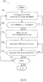
- FIG. 5 depicts a flow diagram representative of operations that may be performed to produce, for example, the example cage retainer 228 ( FIG. 2 ) or any other of the examples described herein.
- FIG. 5 depicts a flow diagram representative of operations that may be performed to produce, for example, the example cage retainer 228 ( FIG. 2 ) or any other of the examples described herein.
- FIG. 5 depicts a flow diagram representative of operations that may be performed to produce, for example, the example cage retainer 228 ( FIG. 2 ) or any other of the examples described herein.
- FIG. 5 depicts a flow diagram representative of operations that may be performed to produce, for example, the example cage retainer 228 ( FIG. 2 ) or any other of the examples described herein.
- FIG. 5 depicts a flow diagram representative of operations that may be performed to produce, for example, the example cage retainer 228 ( FIG. 2 ) or any other of the examples described herein.
- FIG. 5 depicts a flow diagram representative of operations that may be performed to produce,
- the exterior surface 248 of the cage retainer 228 ( FIG. 2 ) is machined (block 502) such that a diameter 264 of the cage retainer 228 ( FIG. 2 ) is substantially similar to a first diameter (e.g., a first predetermined diameter).
- a first diameter e.g., a first predetermined diameter
- the first diameter is relatively smaller than an inner diameter 266 of the bonnet 210 ( FIG. 2 ).
- the first diameter may have a diameter of approximately five millimeters less than the second diameter discussed below.
- the example method 500 determines whether or not the first diameter has been attained (block 504) (e.g., the diameter 264 of the cage retainer 228 ( FIG. 2 ) is substantially similar to the first diameter). If the example method 500 determines that the first diameter has not been attained, control returns to block 502. However, if the example method 500 determines that the first diameter has been attained, control advances to block 506. Alloy is then applied to the exterior surface 248 (block 506) of the cage retainer 228 ( FIG. 2 ) to form the plurality of projections 254 extending from the exterior surface 248, as shown in FIG. 6 , along a longitudinal axis 602 of the cage retainer 228.
- Alloy is then applied to the exterior surface 248 (block 506) of the cage retainer 228 ( FIG. 2 ) to form the plurality of projections 254 extending from the exterior surface 248, as shown in FIG. 6 , along a longitudinal axis 602 of the cage retainer 228.
- the example cage retainer 228 may include three (3) of the projections 254 evenly spaced about the exterior surface 248.
- the cage retainer 228 may include any number of the projections 254 that may be positioned about the exterior surface 248 in any suitable arrangement.
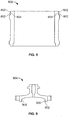
- a plurality of projections 802 may be a plurality of annular rings extending from an exterior surface 804 of a cage retainer 806. While the example depicted in FIG. 8 includes two projections, the example cage retainer 806 may include any number of projections (e.g., 1, 2, 3, 4, etc.).
- FIG. 8 may include any number of projections (e.g., 1, 2, 3, 4, etc.).
- an inner surface 902 of a bonnet 904 may be provided with a plurality of projections 906 as opposed to the exterior surface 248 of the cage retainer 228.
- the projections 906 may extend inwardly from the inner surface 902.
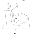
- a portion of the plurality of projections 254 may then be machined (block 508), as shown in FIG. 7 , such that a diameter of the cage retainer 228 ( FIG. 2 ) with the plurality of projections 254 is substantially similar to a second diameter (e.g., a second predetermined diameter).
- the second diameter corresponds to the inner diameter 266 of the bonnet 210.
- each of the plurality of projections 254 is elongated and may include a substantially rectangularly shaped surface 702 that is to at least partially contact the inner surface 250 of the bonnet 210.
- the example method 500 determines whether or not the second diameter has been attained (block 510) (e.g., the diameter of the cage retainer 228 ( FIG. 2 ) including the plurality of projections 254 is substantially similar to the second diameter). If the example method 500 determines that the second diameter has not been attained, control returns to block 508. However, if the example method 500 determines that the second diameter has been attained, control advances to block 512 and the example method 500 determines whether it should machine another cage retainer (block 512). Otherwise the example method 500 of FIG. 5 is ended.
- the second diameter e.g., the diameter of the cage retainer 228 ( FIG. 2 ) including the plurality of projections 254 is substantially similar to the second diameter.
Description
- The present patent relates generally to fluid valves and, more particularly, to fluid valves having dynamic valve trim joints.
- Control valves are commonly used in process plants to control the flow of a fluid (e.g., a gas, a liquid, etc.) or any other substance through pipes and/or vessels to which they are connected. A control valve is typically composed of one or more inlets and outlets, and includes a flow control element or member (e.g., a valve gate, a piston, a valve plug, a closure member, etc.) that operates to control fluid flow through apertures that fluidly couple the inlet(s) to the outlet(s). A closure member is typically coupled to a valve bonnet that is mechanically coupled (e.g., bolted, clamped, threaded into, etc.) to the valve body. Typically, the closure member is configured to engage a sealing structure (e.g., a seat ring) that encompasses a flow path through the valve.
- In some instances, different components of the control valve are made of different materials having different coefficients of thermal expansion. As such, in high temperature applications, the coefficients of thermal expansion of the materials from which the different control valve components are made have to be taken into account.
- Patent Document
EP2042685 relates to a choke assembly, in particular to a choke assembly having a plug and cage type arrangement, and to the use of the choke assembly in the processing of fluid streams. - According to the invention, the problem is solved by the subject-matter outlined in the independent claims. Advantageous further developments of the invention are set forth in the dependent claims.
-
-
FIG. 1 depicts a known fluid valve. -
FIG. 2 depicts an example fluid valve having an example cage retainer and a cage. -
FIG. 3 depicts the example cage retainer ofFIG. 2 having a plurality of projections extending from an exterior surface. -
FIG. 4 depicts an alternative example fluid valve having a spring element between an example cage retainer and a cage. -
FIG. 5 is a flow diagram representative of an example process that may be performed to produce the examples described herein. -
FIG. 6 depicts one of the plurality of projections of the example cage retainer ofFIG. 2 prior to being machined. -
FIG. 7 depicts one of the plurality of projections of the example cage retainer ofFIG. 2 after being machined. -
FIG. 8 depicts another example cage retainer having a plurality of annular projections extending from an exterior surface. -
FIG. 9 depicts an example bonnet having a plurality of projections extending from an inner surface. - Certain examples are shown in the above-identified figures and described in detail below. In describing these examples, like or identical reference numbers are used to identify the same or similar elements. The figures are not necessarily to scale and certain features and certain views of the figures may be shown exaggerated in scale or in schematic for clarity and/or conciseness. Additionally, several examples have been described throughout this specification.
- The examples described herein relate to fluid valves having a dynamic joint between, for example, a cage retainer and a bonnet. Such a dynamic joint allows the cage retainer to move (e.g., slide) relative to the bonnet to accommodate and compensate for thermal expansion or contraction of the valve body, the cage retainer, the bonnet, the cage and/or other valve components. The examples described herein substantially reduce the amount of thermal expansion of the cage retainer by enabling the cage retainer to be made of a material (e.g., a steel material) that is similar to or the same as a material forming a bonnet coupled to the fluid valve. By reducing the amount of thermal expansion of the cage retainer, a cage coaxially aligned with and engaged to the cage retainer may engage a seat ring to maintain the position of the seat ring within the valve body, thereby eliminating the need to use fasteners to couple the seat ring to the valve body. Such an approach may decrease the amount of distortion imparted to the seat ring when coupling the seat ring to the valve body and simplifies the assembly and/or disassembly of the fluid valve.
- In some examples described herein, to enable a cage retainer to be made of a material that is similar to or the same as a material forming a bonnet with which the cage retainer is engaged, a plurality of projections made of a different material than the bonnet material and the cage retainer material are radially positioned around an exterior surface of the cage retainer. In general, the plurality of projections act as a spacer between the exterior surface of the cage retainer and an inner surface of the bonnet, thereby preventing the exterior surface of the cage retainer from continuously engaging the inner surface of the bonnet. Preventing the exterior surface of the cage retainer from continuously engaging the inner surface of the bonnet substantially prevents the cage retainer and the bonnet from becoming fixed (e.g., corroded) together over time and, thus, a dynamic joint between these components may be maintained.
-
FIG. 1 depicts a knownfluid valve 100 that has avalve body 102 having afluid flow passageway 104 between aninlet 106 and anoutlet 108. Abonnet 110 is coupled to thevalve body 102 via a plurality offasteners 112 and includes abore 114 to receive astem 116. Anend 118 of thestem 116 extends from thebonnet 110 and is operatively coupled to an actuator (not shown), and anopposite end 120 of thestem 116 is coupled to a closure member 122 (e.g., a valve plug). - To control fluid flow through the
valve body 102,valve trim 124 is positioned between theinlet 106 and theoutlet 108 to provide certain flow characteristics (e.g., to reduce noise and/or cavitation generated by the flow of fluid through the fluid valve 100). Thevalve trim 124 includes ahanging cage 126, theclosure member 122 and thestem 116. - To secure the hanging
cage 126 relative to thevalve body 102, thehanging cage 126 includes aflange 128 that is positioned in acircumferential groove 130 defined by thevalve body 102 and is engaged by aportion 132 of thebonnet 110. The hangingcage 126 is typically made of a stainless steel material and thevalve body 102 and thebonnet 110 are both typically made of a different steel material having a coefficient of thermal expansion different than the stainless steel material. As such, thehanging cage 126, thevalve body 102 and/or thebonnet 110 may expand and/or contract at different rates and/or amounts as thefluid valve 100 is subjected to, for example, a thermal cycle. To compensate for the difference in the amount and/or rate of thermal expansion/contraction (e.g., thehanging cage 126 expanding at a faster rate and/or more than thevalve body 102 and/or the bonnet 110), agap 134 is provided between anend 136 of thehanging cage 126 and aseat ring 138 positioned at least partially within anaperture 140 of thevalve body 102. Theseat ring 138 is coupled or fixed to thevalve body 102 via a plurality of fasteners 142 (e.g., thirty (30) fasteners). - To provide a seal between the
seat ring 138 and thevalve body 102, a spring loaded seal(s) and/or aspiral wound gasket 144 is positioned between theseat ring 138 and thevalve body 102. During assembly of thevalve 100, as the plurality offasteners 142 are tightened to couple theseat ring 138 to thevalve body 102, the spring loaded seal(s) 144 exerts an opposing force against theseat ring 138 that, in some instances, may distort theseat ring 138. As a result, this distortion may prevent theclosure member 122 from properly (e.g., sealingly) engaging theseat ring 138 and, thus, prevent theclosure member 122 from properly controlling fluid flow through thefluid valve 100. To reduce or eliminate this distortion, after theseat ring 138 is installed (e.g., after thefasteners 142 are tightened) theseat ring 138 may be machined while coupled to thevalve body 102, which is typically a labor intensive and expensive process. -
FIG. 2 depicts anexample fluid valve 200 that has avalve body 202 including afluid flow passageway 204 between aninlet 206 and anoutlet 208. Abonnet 210 is coupled to thevalve body 202 via a plurality offasteners 212 and includes abore 214 to receive astem 216. Anend 218 of thestem 216 extends from abonnet body 220 and is operatively coupled to an actuator (not shown), and anopposite end 222 of thestem 216 is coupled to a closure member 224 (e.g., a valve plug). - In contrast to the
valve trim 124 ofFIG. 1 ,valve trim 226 of thefluid valve 200 includes a cage retainer 228 (e.g., an upper cage retainer or guide), acage 230, theclosure member 224 and thestem 216. - Generally, an
end 232 of thecage retainer 228 is positioned at least partially within thevalve body 202 and adjacent thebonnet 210 and anopposing end 234 of thecage retainer 228 engages anend 236 of thecage 230 such that thecage retainer 228 and thecage 230 are coaxially aligned. Thecage 230 is positioned within thevalve body 202 such that opposing steps orshoulders cage 230 and a seat 242 (e.g., a seat ring) engage and/or interlock to secure theseat 242 at least partially within anaperture 244 of thevalve body 202. Such an approach eliminates the need for a plurality of fasteners (e.g., such as thefasteners 142 ofFIG. 1 ) to secure theseat 242 relative to thevalve body 202 and, thus, the distortion caused, in some instances, when coupling a seat ring (e.g., theseat ring 138 ofFIG. 1 ) to a valve body (e.g., thevalve body 102 ofFIG. 1 ). Additionally, by eliminating the need for a plurality of fasteners to secure theseat 242, theseat 242 may be more easily removed from and/or assembled within theexample fluid valve 200 during, for example, routine maintenance. - However, securing the
seat 242 to thevalve body 202 via thecage 230 and thecage retainer 228 as shown inFIG. 2 eliminates a gap (e.g., thegap 134 ofFIG. 1 ), which enables a hanging cage (e.g., such as the hangingcage 126 ofFIG. 1 ) to expand and/or contract at a different rate and/or amount than a valve body. In the example ofFIG. 2 , instead of providing a gap between thecage 230 and theseat 242 to accommodate thermal expansion/contraction of thecage 230, thecage retainer 228, theseat 242, thevalve body 202 and/or any other valve components, adynamic joint 252 is provided. As described in greater detail below, thedynamic joint 252 allows thecage 230 and thecage retainer 228 to expand/contract (e.g., in response to thermal cycles) while enabling thecage 230 to remain in contact with theseat 242 to maintain theseat 242 in sealing engagement with theaperture 244. - In addition to the
dynamic joint 252, the example ofFIG. 2 is also configured to reduce the total amount of thermal expansion/contraction of thecage 230 and thecage retainer 228 assembly. In particular, thecage retainer 228 may be made of a steel material and thecage 230 may be made of a stainless steel material, which typically expands at a faster rate and/or a greater amount than the steel material of thecage 230. Specifically, in the example ofFIG. 2 , thefluid valve 200 may be provided with thecage retainer 228 made of a first material (e.g., a steel material) that has a relatively lower coefficient of thermal expansion than a second material (e.g., a stainless steel material) forming thecage 230. Using a material having a relatively lower coefficient of thermal expansion to form thecage retainer 228 reduces the total amount of thermal expansion of thecage 230 and thecage retainer 228 assembly by approximately one half (1/2) as compared to a single-piece cage (not shown) made of a stainless steel material or an assembly in which thecage retainer 228 and thecage 230 are both made of a stainless steel material. Additionally, such an approach enables thecage 230 to be made of a substantially non-corrosive material (e.g., a stainless steel), which reduces the likelihood that theclosure member 224 will become seized within thecage 230 and/or fail to engage theseat 242. - Providing the
fluid valve 200 with thecage retainer 228 made of the first material having a relatively lower coefficient of thermal expansion than the second material forming thecage 230 reduces an amount of thermal expansion as compared to the alternatives described above. However, if an outer orexterior surface 248 of thecage retainer 228 were to continuously engage aninner surface 250 of thebonnet 210, over time, corrosion may occur between theouter surface 248 of thecage retainer 228 and theinner surface 250 of thebonnet 210 because thecage retainer 228 and thebonnet 210 may be made of a similar or identical material (e.g., a steel material) having similar or identical coefficients of thermal expansion. Such corrosion may substantially fix thecage retainer 228 relative to thebonnet 210, thereby compromising the operation of the dynamic joint 252 and increasing the difficulty encountered when disassembling thevalve trim 226 of thefluid valve 200. Specifically, if thecage retainer 228 becomes fixed (e.g., corroded) to thebonnet 210 the dynamic joint 252 becomes compromised and thecage retainer 228 may no longer be able to move relative to thebonnet 210 during thermal cycles. As a result, thecage retainer 228 and thecage 230 may fail to maintain theseat 242 in sealing engagement with theaperture 244 of thevalve body 202 and/or the alignment of thevalve trim 226 may be compromised, thereby affecting the performance of thefluid valve 200. - Referring to
FIGS. 2 and3 , to ensure that the operation of the dynamic joint 252 is not compromised due to corrosion or the like, theexterior surface 248 of thecage retainer 228 is provided with a plurality of projections 254 (FIG. 3 ), each having a relatively small surface area, that are radially spaced about theexterior surface 248. While theexample cage retainer 228 is depicted inFIG. 3 as including threeprojections 254, theexample cage retainer 228 may include any number of projections 254 (e.g., 1, 2, 3, etc.) that are similarly or differently shaped. - Generally, each of the
projections 254 provides one or more contact points between theexterior surface 248 of thecage retainer 228 and theinner surface 250 of thebonnet 210, thereby enabling the dynamic joint 252 to be maintained between thecage retainer 228 and thebonnet 210. Specifically, to maintain the dynamic joint 252, each of theprojections 254 may be made of a third material such as, for example, a stellite alloy material, a cobalt alloy material, a non-corrosive material, etc., while thebonnet 210 and thecage retainer 228 may be made of the first material such as, for example, a steel material. The materials from which theprojections 254 and thecage retainer 228 and thebonnet 210 are made substantially prevent thebonnet 210 and thecage retainer 228 from becoming corroded together over time. As discussed above, if theexterior surface 248 of thecage retainer 228 were to engage (e.g., continuously engage) theinner surface 250 of thebonnet 210, this interaction would enable thesurfaces exterior surface 248 may alternatively or additionally be provided with a coating of a non-corrosive material, such as chrome, that acts as a buffer between theexterior surface 248 and theinner surface 250 to maintain the dynamic joint 252. In such examples, theexample cage retainer 228 may not be provided with theprojections 254. - To assemble the
fluid valve 200, theseat 242 is positioned at least partially within theaperture 244 and thecage 230 is inserted into thevalve body 202 to engage and/or interlock the opposingsteps cage 230 and theseat 242, respectively. Thecage retainer 228 is then positioned in thevalve body 202 such that theend 234 of thecage retainer 228 engages theopposing end 236 of thecage 230 and theother end 232 of thecage retainer 228 is positioned adjacent thebonnet 210. Thebonnet 210 may then be aligned and coupled to thevalve body 202 via thefasteners 212. Specifically, aportion 262 of thebonnet 210 is positioned such that theinner surface 250 of thebonnet 210 surrounds theexterior surface 248 of thecage retainer 228 and theprojections 254 are positioned between thesurfaces - To compensate for the difference in the coefficients of thermal expansion of the
cage 230 relative to thecage retainer 228, thevalve body 202 and/or thebonnet 210, a bias element 258 (e.g., a spring or seal) may be positioned adjacent astep 260 defined by thecage retainer 228. Specifically, thebias element 258 may react (e.g., expand or contract) in response to the relative position of thecage retainer 228 and/or thecage 230 within thevalve body 202. For example, as thefluid valve 200 is exposed to heat (e.g., a thermal cycle), thecage 230 may expand (e.g., elongate), thereby moving thecage retainer 228 and, thus, thestep 260 toward thebonnet 210 and compressing thebias element 258. - As discussed above, the
projections 254 positioned between theexterior surface 248 and theinner surface 250 enable the dynamic joint 252 to be maintained and, thus, thecage retainer 228 to be movable relative to thebonnet 210. While thebias element 258 is positioned adjacent thebonnet 210 in the examplefluid valve 200 ofFIG. 2 , thebias element 258 may be positioned in any other suitable position. For example,FIG. 4 depicts anexample fluid valve 400 having aspring element 402 positioned within agroove 404 between acage retainer 406 and acage 408. - The flow diagram depicted in
FIG. 5 is representative of a process ormethod 500 that can be performed to produce the example apparatus described herein. In particular,FIG. 5 depicts a flow diagram representative of operations that may be performed to produce, for example, the example cage retainer 228 (FIG. 2 ) or any other of the examples described herein. Further, although the example operations ofFIG. 5 are described with reference to the flow diagram ofFIG. 5 other methods of implementing themethod 500 ofFIG. 5 may be employed. For example, the order of execution of the blocks may be changed, and/or some of the blocks described may be changed, eliminated, sub-divided, or combined. - Turning in detail to
FIG. 5 and with reference toFIG. 2 , theexterior surface 248 of the cage retainer 228 (FIG. 2 ) is machined (block 502) such that adiameter 264 of the cage retainer 228 (FIG. 2 ) is substantially similar to a first diameter (e.g., a first predetermined diameter). Generally, the first diameter is relatively smaller than aninner diameter 266 of the bonnet 210 (FIG. 2 ). In some examples, the first diameter may have a diameter of approximately five millimeters less than the second diameter discussed below. - The
example method 500 then determines whether or not the first diameter has been attained (block 504) (e.g., thediameter 264 of the cage retainer 228 (FIG. 2 ) is substantially similar to the first diameter). If theexample method 500 determines that the first diameter has not been attained, control returns to block 502. However, if theexample method 500 determines that the first diameter has been attained, control advances to block 506. Alloy is then applied to the exterior surface 248 (block 506) of the cage retainer 228 (FIG. 2 ) to form the plurality ofprojections 254 extending from theexterior surface 248, as shown inFIG. 6 , along alongitudinal axis 602 of thecage retainer 228. - In some examples, as shown in
FIG. 3 , the example cage retainer 228 (FIG. 2 ) may include three (3) of theprojections 254 evenly spaced about theexterior surface 248. However, the cage retainer 228 (FIG. 2 ) may include any number of theprojections 254 that may be positioned about theexterior surface 248 in any suitable arrangement. For example, as shown inFIG. 8 , a plurality ofprojections 802 may be a plurality of annular rings extending from anexterior surface 804 of acage retainer 806. While the example depicted inFIG. 8 includes two projections, theexample cage retainer 806 may include any number of projections (e.g., 1, 2, 3, 4, etc.). Alternatively, as shown inFIG. 9 , aninner surface 902 of abonnet 904 may be provided with a plurality ofprojections 906 as opposed to theexterior surface 248 of thecage retainer 228. In such examples, theprojections 906 may extend inwardly from theinner surface 902. - A portion of the plurality of
projections 254 may then be machined (block 508), as shown inFIG. 7 , such that a diameter of the cage retainer 228 (FIG. 2 ) with the plurality ofprojections 254 is substantially similar to a second diameter (e.g., a second predetermined diameter). Generally, the second diameter corresponds to theinner diameter 266 of thebonnet 210. As depicted inFIG. 7 , in some examples, each of the plurality ofprojections 254 is elongated and may include a substantially rectangularly shapedsurface 702 that is to at least partially contact theinner surface 250 of thebonnet 210. - The
example method 500 then determines whether or not the second diameter has been attained (block 510) (e.g., the diameter of the cage retainer 228 (FIG. 2 ) including the plurality ofprojections 254 is substantially similar to the second diameter). If theexample method 500 determines that the second diameter has not been attained, control returns to block 508. However, if theexample method 500 determines that the second diameter has been attained, control advances to block 512 and theexample method 500 determines whether it should machine another cage retainer (block 512). Otherwise theexample method 500 ofFIG. 5 is ended. - Although certain example methods, apparatus and articles of manufacture have been described herein, the scope of coverage of this patent is not limited thereto. On the contrary, this patent covers all methods, apparatus and articles of manufacture falling within the scope of the appended claims.
Claims (13)
- A fluid valve for controlling fluid flow, comprising:a valve body (202) defining a fluid flow passageway (204) between an inlet port (206) and an outlet port (208);a cage (230) disposed in the fluid flow passageway (204);a cage retainer (228, 806) positioned within the valve body (202) to engage the cage (230);a bonnet (210, 904) coupled to the valve body (202); anda dynamic joint (252) between an exterior surface (248, 804) of the cage retainer (228, 806) and an inner surface (250, 902) of the bonnet (210, 904),wherein the dynamic joint (252) prevents the cage retainer (228, 806) from becoming fixed to the bonnet (210, 904), andwherein the dynamic joint (252) comprises a plurality of spaced apart projections (254, 802, 906) positioned between the inner surface (250, 902) of the bonnet (210, 904) and the exterior surface (248, 804) of the cage retainer (228, 806) to prevent continuous engagement between the exterior surface (248, 804) of the cage retainer (228, 806) and the inner surface of the bonnet (210, 904);characterised bythe cage retainer (228, 806) comprising a first material and each of the plurality of projections (254, 802, 906) comprising a second material different from the first material.
- The fluid valve as defined in claim 1, wherein the cage retainer (228, 806) comprises the projections (254, 802, 906), the projections (254, 802, 906) projecting from the exterior surface (248, 804) of the cage retainer (228, 806).
- The fluid valve as defined in claim 2, wherein at least one of the projections (254) has an elongated shape extending along a longitudinal axis (602) of the cage retainer (228, 806).
- The fluid valve as defined in any one of the previous claims, wherein the projections (254, 802, 906) are radially spaced about the exterior surface (248, 804).
- The fluid valve of claim 2, wherein at least one of the projections (254) comprises an annular ring (802).
- The fluid valve as defined in any one of claims 2 to 5, wherein the exterior surface (248, 804) of the cage retainer (228, 806) has a first diameter (264), the projections (254, 802, 906) define a second diameter, and the second diameter is larger than the first diameter.
- The fluid valve as defined in claim 6, wherein the second diameter corresponds to an inner diameter (266) of the bonnet (210, 904).
- The fluid valve as defined in claim 7, wherein the first material comprises a steel material and the second material comprises a cobalt alloy material.
- The fluid valve as defined in claim 1, wherein the bonnet (210, 904) comprises the projections (906) projecting inwardly from the inner surface (250, 902) of the bonnet (210, 904).
- The fluid valve as defined in any one of the previous claims, wherein the cage (230) is arranged to guide a closure member of the fluid valve.
- The fluid valve as defined in any one of the previous claims, wherein the cage (230) is coaxially aligned with the cage retainer (228, 806).
- A method of producing a cage retainer (228, 806) and a bonnet (210, 904) for use with a fluid valve, the bonnet (210, 904) having an inner surface (250, 902) defining an interior diameter, the method comprising:machining an exterior portion of the cage retainer (228, 806) to have a first diameter;applying an alloy to a surface of the exterior portion to provide the surface with a plurality of projections (254, 802, 906) projecting from and radially spaced about the surface; andmachining a portion of the alloy such that the plurality of projections (254, 802, 906) has a second diameter that corresponds to the inner diameter of the bonnet (210, 904), wherein the second diameter is larger than the first diameter (264) to prevent a continuous engagement between the surface of the exterior portion and an inner surface (250, 902) of the bonnet (210, 904).
- The method as defined in claim 12, wherein the first step of machining comprises machining the first diameter (264) to be smaller than the interior diameter of the bonnet (210, 904).
Applications Claiming Priority (2)
| Application Number | Priority Date | Filing Date | Title |
|---|---|---|---|
| US12/480,425 US8356622B2 (en) | 2009-06-08 | 2009-06-08 | Fluid valves having dynamic valve trim joints |
| PCT/US2010/033762 WO2010144193A1 (en) | 2009-06-08 | 2010-05-05 | Fluid valves having dynamic valve trim joints |
Publications (2)
| Publication Number | Publication Date |
|---|---|
| EP2440819A1 EP2440819A1 (en) | 2012-04-18 |
| EP2440819B1 true EP2440819B1 (en) | 2019-04-10 |
Family
ID=42710815
Family Applications (1)
| Application Number | Title | Priority Date | Filing Date |
|---|---|---|---|
| EP10717433.6A Active EP2440819B1 (en) | 2009-06-08 | 2010-05-05 | Fluid valves having dynamic valve trim joints |
Country Status (11)
| Country | Link |
|---|---|
| US (1) | US8356622B2 (en) |
| EP (1) | EP2440819B1 (en) |
| JP (1) | JP5657650B2 (en) |
| CN (1) | CN102459974B (en) |
| AU (1) | AU2010259183B2 (en) |
| BR (1) | BRPI1013058A2 (en) |
| CA (1) | CA2764803C (en) |
| MX (1) | MX2011013163A (en) |
| NO (1) | NO342482B1 (en) |
| RU (1) | RU2542726C2 (en) |
| WO (1) | WO2010144193A1 (en) |
Families Citing this family (13)
| Publication number | Priority date | Publication date | Assignee | Title |
|---|---|---|---|---|
| US9046191B2 (en) | 2012-08-30 | 2015-06-02 | Fisher Controls International, Llc | Valve body with upper flow diverter |
| CN202972080U (en) * | 2012-10-22 | 2013-06-05 | 费希尔久安输配设备(成都)有限公司 | Valve component |
| WO2014114256A1 (en) * | 2013-01-28 | 2014-07-31 | 费希尔久安输配设备(成都)有限公司 | Piston device and pressure regulator using same |
| JP6163129B2 (en) * | 2014-03-31 | 2017-07-12 | アズビル株式会社 | Cage valve |
| DE102015011551B3 (en) * | 2015-09-02 | 2017-03-02 | Samson Aktiengesellschaft | Control valve for controlling a fluid flow of a process plant |
| US10663083B2 (en) * | 2016-10-21 | 2020-05-26 | Fisher Controls International Llc | Trim assembly having a side branch resonator array and fluid control valve comprising same |
| DE102017123396A1 (en) * | 2017-10-09 | 2019-04-11 | Samson Aktiengesellschaft | Lifting valve and arrangement for a lifting valve |
| RU2717731C1 (en) * | 2019-07-15 | 2020-03-25 | Ирина Александровна Анкудинова | Regulated throttle |
| CN110598301B (en) * | 2019-09-05 | 2022-10-11 | 华北电力科学研究院有限责任公司 | Parameter coupling design method for liquefied air energy storage system |
| US11407070B2 (en) * | 2020-12-14 | 2022-08-09 | Fisher Controls International Llc | Bonnet and valve trim assembly and related methods |
| US11946565B2 (en) * | 2021-02-25 | 2024-04-02 | Hayward Industries, Inc. | Valve assembly |
| US11808378B2 (en) * | 2021-04-13 | 2023-11-07 | Michael Pellegrini | Globe valve assembly |
| CN114704662A (en) * | 2022-04-07 | 2022-07-05 | 江苏亿阀股份有限公司 | High-pressure antistatic stop valve for oxygen and use method thereof |
Family Cites Families (28)
| Publication number | Priority date | Publication date | Assignee | Title |
|---|---|---|---|---|
| US6004A (en) * | 1849-01-09 | chinnqck | ||
| US3019A (en) * | 1843-03-30 | Hatching chickens | ||
| US10028A (en) * | 1853-09-20 | Improvement in razor-strops | ||
| NL137883C (en) * | 1967-09-11 | |||
| JPS4634955Y1 (en) * | 1970-06-12 | 1971-12-02 | ||
| US3742984A (en) * | 1971-09-02 | 1973-07-03 | Acf Ind Inc | Globe valve having hydraulic balancing |
| US3834666A (en) * | 1972-10-02 | 1974-09-10 | Masoneilan Int Inc | Control valve with elastically loaded cage trim |
| JPS5398430U (en) * | 1977-01-13 | 1978-08-10 | ||
| US4149563A (en) * | 1977-02-16 | 1979-04-17 | Copes-Vulcan, Inc. | Anti-cavitation valve |
| SU934130A1 (en) * | 1980-08-28 | 1982-06-07 | Предприятие П/Я А-7755 | Gate valve |
| US4542879A (en) * | 1981-11-27 | 1985-09-24 | Marbor Engineering Associates | Valve ring arrangements in metallic valves, control valves, condensate removal devices, and other means for the prevention of leakages due to corrosion |
| JPS617672U (en) * | 1984-06-20 | 1986-01-17 | トキコ株式会社 | valve device |
| US5012841A (en) * | 1989-08-24 | 1991-05-07 | Keystone International Holdings Corp. | Pressure reducing and conditioning valves |
| US5492146A (en) * | 1992-09-02 | 1996-02-20 | Richards Industries, Inc. | Pressure regulators |
| JPH10132177A (en) * | 1996-10-28 | 1998-05-22 | Sekisui Chem Co Ltd | Pipe end insert |
| JP2000273573A (en) * | 1999-03-26 | 2000-10-03 | Hitachi Ltd | Corrosion resistant and wear resistant alloy and apparatus using the alloy |
| JP2001333995A (en) * | 2000-05-30 | 2001-12-04 | Senju Sprinkler Kk | Valving element guide mechanism of 'all-at-once' open valve and the same valve |
| JP2002089722A (en) * | 2000-09-13 | 2002-03-27 | Tokico Ltd | Pressure control valve |
| US6641110B1 (en) * | 2002-04-22 | 2003-11-04 | Nhan V. Nguyen | Binary balance seal assembly |
| JP4158596B2 (en) * | 2003-05-08 | 2008-10-01 | 株式会社ジェイテクト | Steering device |
| US6932321B2 (en) * | 2003-05-28 | 2005-08-23 | Fisher Controls International Llc | Balanced-plug cage style control valve and bonnet seal assembly |
| US6997211B2 (en) * | 2003-07-03 | 2006-02-14 | Fisher Controls International Llc. | Multiple material valve plug for high temperature operation |
| JP2005076765A (en) * | 2003-09-01 | 2005-03-24 | Unisia Jkc Steering System Co Ltd | Check valve and its manufacturing method |
| US20050151107A1 (en) * | 2003-12-29 | 2005-07-14 | Jianchao Shu | Fluid control system and stem joint |
| US20060049375A1 (en) | 2004-09-07 | 2006-03-09 | Fisher Controls International Llc | Boronized valve seal |
| RU2298128C2 (en) * | 2005-06-06 | 2007-04-27 | Открытое акционерное общество "НПО "Промавтоматика" | Multipurpose valve |
| GB0618165D0 (en) * | 2006-09-15 | 2006-10-25 | Imi Vision Ltd | Improvements in fluid control |
| EP2385212B1 (en) | 2007-09-26 | 2017-11-08 | Cameron International Corporation | Choke assembly |
-
2009
- 2009-06-08 US US12/480,425 patent/US8356622B2/en active Active
-
2010
- 2010-05-05 WO PCT/US2010/033762 patent/WO2010144193A1/en active Application Filing
- 2010-05-05 JP JP2012513953A patent/JP5657650B2/en not_active Expired - Fee Related
- 2010-05-05 CN CN201080025321.7A patent/CN102459974B/en active Active
- 2010-05-05 EP EP10717433.6A patent/EP2440819B1/en active Active
- 2010-05-05 MX MX2011013163A patent/MX2011013163A/en active IP Right Grant
- 2010-05-05 CA CA2764803A patent/CA2764803C/en active Active
- 2010-05-05 AU AU2010259183A patent/AU2010259183B2/en not_active Ceased
- 2010-05-05 RU RU2011152814/06A patent/RU2542726C2/en active
- 2010-05-05 BR BRPI1013058A patent/BRPI1013058A2/en not_active Application Discontinuation
-
2011
- 2011-12-06 NO NO20111684A patent/NO342482B1/en not_active IP Right Cessation
Non-Patent Citations (1)
| Title |
|---|
| None * |
Also Published As
| Publication number | Publication date |
|---|---|
| AU2010259183B2 (en) | 2016-02-25 |
| AU2010259183A1 (en) | 2011-12-15 |
| NO20111684A1 (en) | 2011-12-06 |
| EP2440819A1 (en) | 2012-04-18 |
| WO2010144193A1 (en) | 2010-12-16 |
| NO342482B1 (en) | 2018-05-28 |
| US20100307610A1 (en) | 2010-12-09 |
| RU2011152814A (en) | 2013-07-20 |
| US8356622B2 (en) | 2013-01-22 |
| JP5657650B2 (en) | 2015-01-21 |
| RU2542726C2 (en) | 2015-02-27 |
| CA2764803A1 (en) | 2010-12-16 |
| CA2764803C (en) | 2016-08-09 |
| JP2012529599A (en) | 2012-11-22 |
| CN102459974A (en) | 2012-05-16 |
| CN102459974B (en) | 2014-07-16 |
| BRPI1013058A2 (en) | 2016-04-05 |
| MX2011013163A (en) | 2012-01-30 |
Similar Documents
| Publication | Publication Date | Title |
|---|---|---|
| EP2440819B1 (en) | Fluid valves having dynamic valve trim joints | |
| US8720854B2 (en) | Floating ball valve seal with dynamic C-seal and static C-seal | |
| EP2282093B1 (en) | Control valve having "c" seal | |
| JP5511673B2 (en) | Flow controller and method for assembling a flow controller | |
| EP2240716B1 (en) | Seal assembly for use with valves having a two-piece cage | |
| EP2733402B1 (en) | Pressure balanced spring loaded overtravel sealing apparatus | |
| AU2011245603A1 (en) | Ball valve seal with dynamic C-seal and static C-seal | |
| US10533668B2 (en) | Seal assemblies for use with fluid valves | |
| MX2011012617A (en) | Valve seat apparatus for use with fluid valves. | |
| EP3658806B1 (en) | Seal assemblies for use with fluid valves | |
| US11287057B2 (en) | Y-globe valve assembly with integrated pressure relief passageway | |
| US11852262B2 (en) | Heat tracing systems for fluid valves and related methods | |
| WO2023186926A1 (en) | Device for controlling passage of fluid |
Legal Events
| Date | Code | Title | Description |
|---|---|---|---|
| PUAI | Public reference made under article 153(3) epc to a published international application that has entered the european phase |
Free format text: ORIGINAL CODE: 0009012 |
|
| 17P | Request for examination filed |
Effective date: 20111206 |
|
| AK | Designated contracting states |
Kind code of ref document: A1 Designated state(s): AL AT BE BG CH CY CZ DE DK EE ES FI FR GB GR HR HU IE IS IT LI LT LU LV MC MK MT NL NO PL PT RO SE SI SK SM TR |
|
| DAX | Request for extension of the european patent (deleted) | ||
| 17Q | First examination report despatched |
Effective date: 20151104 |
|
| STAA | Information on the status of an ep patent application or granted ep patent |
Free format text: STATUS: EXAMINATION IS IN PROGRESS |
|
| GRAP | Despatch of communication of intention to grant a patent |
Free format text: ORIGINAL CODE: EPIDOSNIGR1 |
|
| STAA | Information on the status of an ep patent application or granted ep patent |
Free format text: STATUS: GRANT OF PATENT IS INTENDED |
|
| INTG | Intention to grant announced |
Effective date: 20181031 |
|
| GRAS | Grant fee paid |
Free format text: ORIGINAL CODE: EPIDOSNIGR3 |
|
| GRAA | (expected) grant |
Free format text: ORIGINAL CODE: 0009210 |
|
| STAA | Information on the status of an ep patent application or granted ep patent |
Free format text: STATUS: THE PATENT HAS BEEN GRANTED |
|
| AK | Designated contracting states |
Kind code of ref document: B1 Designated state(s): AL AT BE BG CH CY CZ DE DK EE ES FI FR GB GR HR HU IE IS IT LI LT LU LV MC MK MT NL NO PL PT RO SE SI SK SM TR |
|
| REG | Reference to a national code |
Ref country code: GB Ref legal event code: FG4D |
|
| REG | Reference to a national code |
Ref country code: CH Ref legal event code: EP Ref country code: AT Ref legal event code: REF Ref document number: 1119122 Country of ref document: AT Kind code of ref document: T Effective date: 20190415 |
|
| REG | Reference to a national code |
Ref country code: DE Ref legal event code: R096 Ref document number: 602010058134 Country of ref document: DE |
|
| REG | Reference to a national code |
Ref country code: IE Ref legal event code: FG4D |
|
| REG | Reference to a national code |
Ref country code: NL Ref legal event code: MP Effective date: 20190410 |
|
| REG | Reference to a national code |
Ref country code: LT Ref legal event code: MG4D |
|
| REG | Reference to a national code |
Ref country code: AT Ref legal event code: MK05 Ref document number: 1119122 Country of ref document: AT Kind code of ref document: T Effective date: 20190410 |
|
| PG25 | Lapsed in a contracting state [announced via postgrant information from national office to epo] |
Ref country code: NL Free format text: LAPSE BECAUSE OF FAILURE TO SUBMIT A TRANSLATION OF THE DESCRIPTION OR TO PAY THE FEE WITHIN THE PRESCRIBED TIME-LIMIT Effective date: 20190410 |
|
| PG25 | Lapsed in a contracting state [announced via postgrant information from national office to epo] |
Ref country code: AL Free format text: LAPSE BECAUSE OF FAILURE TO SUBMIT A TRANSLATION OF THE DESCRIPTION OR TO PAY THE FEE WITHIN THE PRESCRIBED TIME-LIMIT Effective date: 20190410 Ref country code: ES Free format text: LAPSE BECAUSE OF FAILURE TO SUBMIT A TRANSLATION OF THE DESCRIPTION OR TO PAY THE FEE WITHIN THE PRESCRIBED TIME-LIMIT Effective date: 20190410 Ref country code: SE Free format text: LAPSE BECAUSE OF FAILURE TO SUBMIT A TRANSLATION OF THE DESCRIPTION OR TO PAY THE FEE WITHIN THE PRESCRIBED TIME-LIMIT Effective date: 20190410 Ref country code: HR Free format text: LAPSE BECAUSE OF FAILURE TO SUBMIT A TRANSLATION OF THE DESCRIPTION OR TO PAY THE FEE WITHIN THE PRESCRIBED TIME-LIMIT Effective date: 20190410 Ref country code: NO Free format text: LAPSE BECAUSE OF FAILURE TO SUBMIT A TRANSLATION OF THE DESCRIPTION OR TO PAY THE FEE WITHIN THE PRESCRIBED TIME-LIMIT Effective date: 20190710 Ref country code: PT Free format text: LAPSE BECAUSE OF FAILURE TO SUBMIT A TRANSLATION OF THE DESCRIPTION OR TO PAY THE FEE WITHIN THE PRESCRIBED TIME-LIMIT Effective date: 20190910 Ref country code: LT Free format text: LAPSE BECAUSE OF FAILURE TO SUBMIT A TRANSLATION OF THE DESCRIPTION OR TO PAY THE FEE WITHIN THE PRESCRIBED TIME-LIMIT Effective date: 20190410 Ref country code: FI Free format text: LAPSE BECAUSE OF FAILURE TO SUBMIT A TRANSLATION OF THE DESCRIPTION OR TO PAY THE FEE WITHIN THE PRESCRIBED TIME-LIMIT Effective date: 20190410 |
|
| PG25 | Lapsed in a contracting state [announced via postgrant information from national office to epo] |
Ref country code: PL Free format text: LAPSE BECAUSE OF FAILURE TO SUBMIT A TRANSLATION OF THE DESCRIPTION OR TO PAY THE FEE WITHIN THE PRESCRIBED TIME-LIMIT Effective date: 20190410 Ref country code: LV Free format text: LAPSE BECAUSE OF FAILURE TO SUBMIT A TRANSLATION OF THE DESCRIPTION OR TO PAY THE FEE WITHIN THE PRESCRIBED TIME-LIMIT Effective date: 20190410 Ref country code: BG Free format text: LAPSE BECAUSE OF FAILURE TO SUBMIT A TRANSLATION OF THE DESCRIPTION OR TO PAY THE FEE WITHIN THE PRESCRIBED TIME-LIMIT Effective date: 20190710 Ref country code: GR Free format text: LAPSE BECAUSE OF FAILURE TO SUBMIT A TRANSLATION OF THE DESCRIPTION OR TO PAY THE FEE WITHIN THE PRESCRIBED TIME-LIMIT Effective date: 20190711 |
|
| REG | Reference to a national code |
Ref country code: DE Ref legal event code: R119 Ref document number: 602010058134 Country of ref document: DE |
|
| REG | Reference to a national code |
Ref country code: CH Ref legal event code: PL |
|
| PG25 | Lapsed in a contracting state [announced via postgrant information from national office to epo] |
Ref country code: IS Free format text: LAPSE BECAUSE OF FAILURE TO SUBMIT A TRANSLATION OF THE DESCRIPTION OR TO PAY THE FEE WITHIN THE PRESCRIBED TIME-LIMIT Effective date: 20190810 Ref country code: AT Free format text: LAPSE BECAUSE OF FAILURE TO SUBMIT A TRANSLATION OF THE DESCRIPTION OR TO PAY THE FEE WITHIN THE PRESCRIBED TIME-LIMIT Effective date: 20190410 |
|
| PG25 | Lapsed in a contracting state [announced via postgrant information from national office to epo] |
Ref country code: MC Free format text: LAPSE BECAUSE OF FAILURE TO SUBMIT A TRANSLATION OF THE DESCRIPTION OR TO PAY THE FEE WITHIN THE PRESCRIBED TIME-LIMIT Effective date: 20190410 Ref country code: CH Free format text: LAPSE BECAUSE OF NON-PAYMENT OF DUE FEES Effective date: 20190531 Ref country code: LI Free format text: LAPSE BECAUSE OF NON-PAYMENT OF DUE FEES Effective date: 20190531 Ref country code: DK Free format text: LAPSE BECAUSE OF FAILURE TO SUBMIT A TRANSLATION OF THE DESCRIPTION OR TO PAY THE FEE WITHIN THE PRESCRIBED TIME-LIMIT Effective date: 20190410 Ref country code: SK Free format text: LAPSE BECAUSE OF FAILURE TO SUBMIT A TRANSLATION OF THE DESCRIPTION OR TO PAY THE FEE WITHIN THE PRESCRIBED TIME-LIMIT Effective date: 20190410 Ref country code: EE Free format text: LAPSE BECAUSE OF FAILURE TO SUBMIT A TRANSLATION OF THE DESCRIPTION OR TO PAY THE FEE WITHIN THE PRESCRIBED TIME-LIMIT Effective date: 20190410 Ref country code: RO Free format text: LAPSE BECAUSE OF FAILURE TO SUBMIT A TRANSLATION OF THE DESCRIPTION OR TO PAY THE FEE WITHIN THE PRESCRIBED TIME-LIMIT Effective date: 20190410 Ref country code: CZ Free format text: LAPSE BECAUSE OF FAILURE TO SUBMIT A TRANSLATION OF THE DESCRIPTION OR TO PAY THE FEE WITHIN THE PRESCRIBED TIME-LIMIT Effective date: 20190410 |
|
| REG | Reference to a national code |
Ref country code: BE Ref legal event code: MM Effective date: 20190531 |
|
| PLBE | No opposition filed within time limit |
Free format text: ORIGINAL CODE: 0009261 |
|
| STAA | Information on the status of an ep patent application or granted ep patent |
Free format text: STATUS: NO OPPOSITION FILED WITHIN TIME LIMIT |
|
| PG25 | Lapsed in a contracting state [announced via postgrant information from national office to epo] |
Ref country code: LU Free format text: LAPSE BECAUSE OF NON-PAYMENT OF DUE FEES Effective date: 20190505 Ref country code: IT Free format text: LAPSE BECAUSE OF FAILURE TO SUBMIT A TRANSLATION OF THE DESCRIPTION OR TO PAY THE FEE WITHIN THE PRESCRIBED TIME-LIMIT Effective date: 20190410 Ref country code: SM Free format text: LAPSE BECAUSE OF FAILURE TO SUBMIT A TRANSLATION OF THE DESCRIPTION OR TO PAY THE FEE WITHIN THE PRESCRIBED TIME-LIMIT Effective date: 20190410 |
|
| 26N | No opposition filed |
Effective date: 20200113 |
|
| PG25 | Lapsed in a contracting state [announced via postgrant information from national office to epo] |
Ref country code: TR Free format text: LAPSE BECAUSE OF FAILURE TO SUBMIT A TRANSLATION OF THE DESCRIPTION OR TO PAY THE FEE WITHIN THE PRESCRIBED TIME-LIMIT Effective date: 20190410 |
|
| PG25 | Lapsed in a contracting state [announced via postgrant information from national office to epo] |
Ref country code: IE Free format text: LAPSE BECAUSE OF NON-PAYMENT OF DUE FEES Effective date: 20190505 Ref country code: DE Free format text: LAPSE BECAUSE OF NON-PAYMENT OF DUE FEES Effective date: 20191203 |
|
| PG25 | Lapsed in a contracting state [announced via postgrant information from national office to epo] |
Ref country code: BE Free format text: LAPSE BECAUSE OF NON-PAYMENT OF DUE FEES Effective date: 20190531 Ref country code: SI Free format text: LAPSE BECAUSE OF FAILURE TO SUBMIT A TRANSLATION OF THE DESCRIPTION OR TO PAY THE FEE WITHIN THE PRESCRIBED TIME-LIMIT Effective date: 20190410 |
|
| PG25 | Lapsed in a contracting state [announced via postgrant information from national office to epo] |
Ref country code: CY Free format text: LAPSE BECAUSE OF FAILURE TO SUBMIT A TRANSLATION OF THE DESCRIPTION OR TO PAY THE FEE WITHIN THE PRESCRIBED TIME-LIMIT Effective date: 20190410 |
|
| PG25 | Lapsed in a contracting state [announced via postgrant information from national office to epo] |
Ref country code: HU Free format text: LAPSE BECAUSE OF FAILURE TO SUBMIT A TRANSLATION OF THE DESCRIPTION OR TO PAY THE FEE WITHIN THE PRESCRIBED TIME-LIMIT; INVALID AB INITIO Effective date: 20100505 Ref country code: MT Free format text: LAPSE BECAUSE OF FAILURE TO SUBMIT A TRANSLATION OF THE DESCRIPTION OR TO PAY THE FEE WITHIN THE PRESCRIBED TIME-LIMIT Effective date: 20190410 |
|
| PG25 | Lapsed in a contracting state [announced via postgrant information from national office to epo] |
Ref country code: MK Free format text: LAPSE BECAUSE OF FAILURE TO SUBMIT A TRANSLATION OF THE DESCRIPTION OR TO PAY THE FEE WITHIN THE PRESCRIBED TIME-LIMIT Effective date: 20190410 |
|
| P01 | Opt-out of the competence of the unified patent court (upc) registered |
Effective date: 20230526 |
|
| PGFP | Annual fee paid to national office [announced via postgrant information from national office to epo] |
Ref country code: FR Payment date: 20230420 Year of fee payment: 14 |
|
| PGFP | Annual fee paid to national office [announced via postgrant information from national office to epo] |
Ref country code: GB Payment date: 20230420 Year of fee payment: 14 |