EP2440819B1 - Flüssigkeitsventile mit dynamischen ventilgarniturverbindungen - Google Patents
Flüssigkeitsventile mit dynamischen ventilgarniturverbindungen Download PDFInfo
- Publication number
- EP2440819B1 EP2440819B1 EP10717433.6A EP10717433A EP2440819B1 EP 2440819 B1 EP2440819 B1 EP 2440819B1 EP 10717433 A EP10717433 A EP 10717433A EP 2440819 B1 EP2440819 B1 EP 2440819B1
- Authority
- EP
- European Patent Office
- Prior art keywords
- cage
- bonnet
- diameter
- projections
- cage retainer
- Prior art date
- Legal status (The legal status is an assumption and is not a legal conclusion. Google has not performed a legal analysis and makes no representation as to the accuracy of the status listed.)
- Active
Links
- 239000012530 fluid Substances 0.000 title claims description 48
- 239000000463 material Substances 0.000 claims description 40
- 238000000034 method Methods 0.000 claims description 20
- 229910000831 Steel Inorganic materials 0.000 claims description 8
- 239000010959 steel Substances 0.000 claims description 8
- 239000000956 alloy Substances 0.000 claims description 6
- 229910045601 alloy Inorganic materials 0.000 claims description 3
- 229910000531 Co alloy Inorganic materials 0.000 claims description 2
- 238000003754 machining Methods 0.000 claims 4
- 239000010935 stainless steel Substances 0.000 description 7
- 229910001220 stainless steel Inorganic materials 0.000 description 7
- 230000008602 contraction Effects 0.000 description 4
- 238000010586 diagram Methods 0.000 description 4
- 238000013459 approach Methods 0.000 description 3
- 230000001010 compromised effect Effects 0.000 description 3
- 238000005260 corrosion Methods 0.000 description 3
- 230000007797 corrosion Effects 0.000 description 3
- 230000009972 noncorrosive effect Effects 0.000 description 3
- 238000007789 sealing Methods 0.000 description 3
- 230000008878 coupling Effects 0.000 description 2
- 238000010168 coupling process Methods 0.000 description 2
- 238000005859 coupling reaction Methods 0.000 description 2
- 238000004519 manufacturing process Methods 0.000 description 2
- VYZAMTAEIAYCRO-UHFFFAOYSA-N Chromium Chemical compound [Cr] VYZAMTAEIAYCRO-UHFFFAOYSA-N 0.000 description 1
- 229910001347 Stellite Inorganic materials 0.000 description 1
- AHICWQREWHDHHF-UHFFFAOYSA-N chromium;cobalt;iron;manganese;methane;molybdenum;nickel;silicon;tungsten Chemical compound C.[Si].[Cr].[Mn].[Fe].[Co].[Ni].[Mo].[W] AHICWQREWHDHHF-UHFFFAOYSA-N 0.000 description 1
- 239000011248 coating agent Substances 0.000 description 1
- 238000000576 coating method Methods 0.000 description 1
- 230000001419 dependent effect Effects 0.000 description 1
- 238000011161 development Methods 0.000 description 1
- 230000018109 developmental process Effects 0.000 description 1
- 230000003993 interaction Effects 0.000 description 1
- 239000007788 liquid Substances 0.000 description 1
- 238000012423 maintenance Methods 0.000 description 1
- 238000012545 processing Methods 0.000 description 1
- 125000006850 spacer group Chemical group 0.000 description 1
- 239000000126 substance Substances 0.000 description 1
Images


Classifications
-
- F—MECHANICAL ENGINEERING; LIGHTING; HEATING; WEAPONS; BLASTING
- F16—ENGINEERING ELEMENTS AND UNITS; GENERAL MEASURES FOR PRODUCING AND MAINTAINING EFFECTIVE FUNCTIONING OF MACHINES OR INSTALLATIONS; THERMAL INSULATION IN GENERAL
- F16K—VALVES; TAPS; COCKS; ACTUATING-FLOATS; DEVICES FOR VENTING OR AERATING
- F16K25/00—Details relating to contact between valve members and seats
- F16K25/04—Arrangements for preventing erosion, not otherwise provided for
-
- F—MECHANICAL ENGINEERING; LIGHTING; HEATING; WEAPONS; BLASTING
- F16—ENGINEERING ELEMENTS AND UNITS; GENERAL MEASURES FOR PRODUCING AND MAINTAINING EFFECTIVE FUNCTIONING OF MACHINES OR INSTALLATIONS; THERMAL INSULATION IN GENERAL
- F16K—VALVES; TAPS; COCKS; ACTUATING-FLOATS; DEVICES FOR VENTING OR AERATING
- F16K3/00—Gate valves or sliding valves, i.e. cut-off apparatus with closing members having a sliding movement along the seat for opening and closing
- F16K3/22—Gate valves or sliding valves, i.e. cut-off apparatus with closing members having a sliding movement along the seat for opening and closing with sealing faces shaped as surfaces of solids of revolution
- F16K3/24—Gate valves or sliding valves, i.e. cut-off apparatus with closing members having a sliding movement along the seat for opening and closing with sealing faces shaped as surfaces of solids of revolution with cylindrical valve members
- F16K3/246—Combination of a sliding valve and a lift valve
-
- F—MECHANICAL ENGINEERING; LIGHTING; HEATING; WEAPONS; BLASTING
- F16—ENGINEERING ELEMENTS AND UNITS; GENERAL MEASURES FOR PRODUCING AND MAINTAINING EFFECTIVE FUNCTIONING OF MACHINES OR INSTALLATIONS; THERMAL INSULATION IN GENERAL
- F16K—VALVES; TAPS; COCKS; ACTUATING-FLOATS; DEVICES FOR VENTING OR AERATING
- F16K47/00—Means in valves for absorbing fluid energy
- F16K47/08—Means in valves for absorbing fluid energy for decreasing pressure or noise level and having a throttling member separate from the closure member, e.g. screens, slots, labyrinths
-
- Y—GENERAL TAGGING OF NEW TECHNOLOGICAL DEVELOPMENTS; GENERAL TAGGING OF CROSS-SECTIONAL TECHNOLOGIES SPANNING OVER SEVERAL SECTIONS OF THE IPC; TECHNICAL SUBJECTS COVERED BY FORMER USPC CROSS-REFERENCE ART COLLECTIONS [XRACs] AND DIGESTS
- Y10—TECHNICAL SUBJECTS COVERED BY FORMER USPC
- Y10T—TECHNICAL SUBJECTS COVERED BY FORMER US CLASSIFICATION
- Y10T137/00—Fluid handling
- Y10T137/7504—Removable valve head and seat unit
- Y10T137/7668—Retained by bonnet or closure
-
- Y—GENERAL TAGGING OF NEW TECHNOLOGICAL DEVELOPMENTS; GENERAL TAGGING OF CROSS-SECTIONAL TECHNOLOGIES SPANNING OVER SEVERAL SECTIONS OF THE IPC; TECHNICAL SUBJECTS COVERED BY FORMER USPC CROSS-REFERENCE ART COLLECTIONS [XRACs] AND DIGESTS
- Y10—TECHNICAL SUBJECTS COVERED BY FORMER USPC
- Y10T—TECHNICAL SUBJECTS COVERED BY FORMER US CLASSIFICATION
- Y10T137/00—Fluid handling
- Y10T137/7722—Line condition change responsive valves
- Y10T137/7737—Thermal responsive
Definitions
- the present patent relates generally to fluid valves and, more particularly, to fluid valves having dynamic valve trim joints.
- Control valves are commonly used in process plants to control the flow of a fluid (e.g., a gas, a liquid, etc.) or any other substance through pipes and/or vessels to which they are connected.
- a control valve is typically composed of one or more inlets and outlets, and includes a flow control element or member (e.g., a valve gate, a piston, a valve plug, a closure member, etc.) that operates to control fluid flow through apertures that fluidly couple the inlet(s) to the outlet(s).
- a closure member is typically coupled to a valve bonnet that is mechanically coupled (e.g., bolted, clamped, threaded into, etc.) to the valve body.
- the closure member is configured to engage a sealing structure (e.g., a seat ring) that encompasses a flow path through the valve.
- different components of the control valve are made of different materials having different coefficients of thermal expansion. As such, in high temperature applications, the coefficients of thermal expansion of the materials from which the different control valve components are made have to be taken into account.
- Patent Document EP2042685 relates to a choke assembly, in particular to a choke assembly having a plug and cage type arrangement, and to the use of the choke assembly in the processing of fluid streams.
- the examples described herein relate to fluid valves having a dynamic joint between, for example, a cage retainer and a bonnet.
- a dynamic joint allows the cage retainer to move (e.g., slide) relative to the bonnet to accommodate and compensate for thermal expansion or contraction of the valve body, the cage retainer, the bonnet, the cage and/or other valve components.
- the examples described herein substantially reduce the amount of thermal expansion of the cage retainer by enabling the cage retainer to be made of a material (e.g., a steel material) that is similar to or the same as a material forming a bonnet coupled to the fluid valve.
- a cage coaxially aligned with and engaged to the cage retainer may engage a seat ring to maintain the position of the seat ring within the valve body, thereby eliminating the need to use fasteners to couple the seat ring to the valve body.
- Such an approach may decrease the amount of distortion imparted to the seat ring when coupling the seat ring to the valve body and simplifies the assembly and/or disassembly of the fluid valve.
- a plurality of projections made of a different material than the bonnet material and the cage retainer material are radially positioned around an exterior surface of the cage retainer.
- the plurality of projections act as a spacer between the exterior surface of the cage retainer and an inner surface of the bonnet, thereby preventing the exterior surface of the cage retainer from continuously engaging the inner surface of the bonnet.
- Preventing the exterior surface of the cage retainer from continuously engaging the inner surface of the bonnet substantially prevents the cage retainer and the bonnet from becoming fixed (e.g., corroded) together over time and, thus, a dynamic joint between these components may be maintained.
- FIG. 1 depicts a known fluid valve 100 that has a valve body 102 having a fluid flow passageway 104 between an inlet 106 and an outlet 108.
- a bonnet 110 is coupled to the valve body 102 via a plurality of fasteners 112 and includes a bore 114 to receive a stem 116.
- An end 118 of the stem 116 extends from the bonnet 110 and is operatively coupled to an actuator (not shown), and an opposite end 120 of the stem 116 is coupled to a closure member 122 (e.g., a valve plug).
- a closure member 122 e.g., a valve plug
- valve trim 124 is positioned between the inlet 106 and the outlet 108 to provide certain flow characteristics (e.g., to reduce noise and/or cavitation generated by the flow of fluid through the fluid valve 100).
- the valve trim 124 includes a hanging cage 126, the closure member 122 and the stem 116.
- the hanging cage 126 includes a flange 128 that is positioned in a circumferential groove 130 defined by the valve body 102 and is engaged by a portion 132 of the bonnet 110.
- the hanging cage 126 is typically made of a stainless steel material and the valve body 102 and the bonnet 110 are both typically made of a different steel material having a coefficient of thermal expansion different than the stainless steel material. As such, the hanging cage 126, the valve body 102 and/or the bonnet 110 may expand and/or contract at different rates and/or amounts as the fluid valve 100 is subjected to, for example, a thermal cycle.
- a gap 134 is provided between an end 136 of the hanging cage 126 and a seat ring 138 positioned at least partially within an aperture 140 of the valve body 102.
- the seat ring 138 is coupled or fixed to the valve body 102 via a plurality of fasteners 142 (e.g., thirty (30) fasteners).
- a spring loaded seal(s) and/or a spiral wound gasket 144 is positioned between the seat ring 138 and the valve body 102.
- the spring loaded seal(s) 144 exerts an opposing force against the seat ring 138 that, in some instances, may distort the seat ring 138.
- this distortion may prevent the closure member 122 from properly (e.g., sealingly) engaging the seat ring 138 and, thus, prevent the closure member 122 from properly controlling fluid flow through the fluid valve 100.
- the seat ring 138 may be machined while coupled to the valve body 102, which is typically a labor intensive and expensive process.
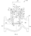
- FIG. 2 depicts an example fluid valve 200 that has a valve body 202 including a fluid flow passageway 204 between an inlet 206 and an outlet 208.
- a bonnet 210 is coupled to the valve body 202 via a plurality of fasteners 212 and includes a bore 214 to receive a stem 216.
- An end 218 of the stem 216 extends from a bonnet body 220 and is operatively coupled to an actuator (not shown), and an opposite end 222 of the stem 216 is coupled to a closure member 224 (e.g., a valve plug).
- a closure member 224 e.g., a valve plug
- valve trim 226 of the fluid valve 200 includes a cage retainer 228 (e.g., an upper cage retainer or guide), a cage 230, the closure member 224 and the stem 216.
- a cage retainer 228 e.g., an upper cage retainer or guide
- cage 230 e.g., the closure member 224 and the stem 216.
- an end 232 of the cage retainer 228 is positioned at least partially within the valve body 202 and adjacent the bonnet 210 and an opposing end 234 of the cage retainer 228 engages an end 236 of the cage 230 such that the cage retainer 228 and the cage 230 are coaxially aligned.
- the cage 230 is positioned within the valve body 202 such that opposing steps or shoulders 238 and 240 of the cage 230 and a seat 242 (e.g., a seat ring) engage and/or interlock to secure the seat 242 at least partially within an aperture 244 of the valve body 202.
- a seat 242 e.g., a seat ring
- the seat 242 may be more easily removed from and/or assembled within the example fluid valve 200 during, for example, routine maintenance.
- securing the seat 242 to the valve body 202 via the cage 230 and the cage retainer 228 as shown in FIG. 2 eliminates a gap (e.g., the gap 134 of FIG. 1 ), which enables a hanging cage (e.g., such as the hanging cage 126 of FIG. 1 ) to expand and/or contract at a different rate and/or amount than a valve body.
- a dynamic joint 252 is provided instead of providing a gap between the cage 230 and the seat 242 to accommodate thermal expansion/contraction of the cage 230, the cage retainer 228, the seat 242, the valve body 202 and/or any other valve components.
- the dynamic joint 252 allows the cage 230 and the cage retainer 228 to expand/contract (e.g., in response to thermal cycles) while enabling the cage 230 to remain in contact with the seat 242 to maintain the seat 242 in sealing engagement with the aperture 244.
- the example of FIG. 2 is also configured to reduce the total amount of thermal expansion/contraction of the cage 230 and the cage retainer 228 assembly.
- the cage retainer 228 may be made of a steel material and the cage 230 may be made of a stainless steel material, which typically expands at a faster rate and/or a greater amount than the steel material of the cage 230.
- the fluid valve 200 may be provided with the cage retainer 228 made of a first material (e.g., a steel material) that has a relatively lower coefficient of thermal expansion than a second material (e.g., a stainless steel material) forming the cage 230.
- Using a material having a relatively lower coefficient of thermal expansion to form the cage retainer 228 reduces the total amount of thermal expansion of the cage 230 and the cage retainer 228 assembly by approximately one half (1/2) as compared to a single-piece cage (not shown) made of a stainless steel material or an assembly in which the cage retainer 228 and the cage 230 are both made of a stainless steel material. Additionally, such an approach enables the cage 230 to be made of a substantially non-corrosive material (e.g., a stainless steel), which reduces the likelihood that the closure member 224 will become seized within the cage 230 and/or fail to engage the seat 242.
- a substantially non-corrosive material e.g., a stainless steel
- Providing the fluid valve 200 with the cage retainer 228 made of the first material having a relatively lower coefficient of thermal expansion than the second material forming the cage 230 reduces an amount of thermal expansion as compared to the alternatives described above.
- an outer or exterior surface 248 of the cage retainer 228 were to continuously engage an inner surface 250 of the bonnet 210, over time, corrosion may occur between the outer surface 248 of the cage retainer 228 and the inner surface 250 of the bonnet 210 because the cage retainer 228 and the bonnet 210 may be made of a similar or identical material (e.g., a steel material) having similar or identical coefficients of thermal expansion.
- Such corrosion may substantially fix the cage retainer 228 relative to the bonnet 210, thereby compromising the operation of the dynamic joint 252 and increasing the difficulty encountered when disassembling the valve trim 226 of the fluid valve 200.
- the cage retainer 228 becomes fixed (e.g., corroded) to the bonnet 210 the dynamic joint 252 becomes compromised and the cage retainer 228 may no longer be able to move relative to the bonnet 210 during thermal cycles.
- the cage retainer 228 and the cage 230 may fail to maintain the seat 242 in sealing engagement with the aperture 244 of the valve body 202 and/or the alignment of the valve trim 226 may be compromised, thereby affecting the performance of the fluid valve 200.
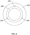
- the exterior surface 248 of the cage retainer 228 is provided with a plurality of projections 254 ( FIG. 3 ), each having a relatively small surface area, that are radially spaced about the exterior surface 248. While the example cage retainer 228 is depicted in FIG. 3 as including three projections 254, the example cage retainer 228 may include any number of projections 254 (e.g., 1, 2, 3, etc.) that are similarly or differently shaped.
- each of the projections 254 provides one or more contact points between the exterior surface 248 of the cage retainer 228 and the inner surface 250 of the bonnet 210, thereby enabling the dynamic joint 252 to be maintained between the cage retainer 228 and the bonnet 210.
- each of the projections 254 may be made of a third material such as, for example, a stellite alloy material, a cobalt alloy material, a non-corrosive material, etc., while the bonnet 210 and the cage retainer 228 may be made of the first material such as, for example, a steel material.
- the exterior surface 248 of the cage retainer 228 were to engage (e.g., continuously engage) the inner surface 250 of the bonnet 210, this interaction would enable the surfaces 248 and 250 to become corroded together.
- the exterior surface 248 may alternatively or additionally be provided with a coating of a non-corrosive material, such as chrome, that acts as a buffer between the exterior surface 248 and the inner surface 250 to maintain the dynamic joint 252.
- the example cage retainer 228 may not be provided with the projections 254.
- the seat 242 is positioned at least partially within the aperture 244 and the cage 230 is inserted into the valve body 202 to engage and/or interlock the opposing steps 238 and 240 of the cage 230 and the seat 242, respectively.
- the cage retainer 228 is then positioned in the valve body 202 such that the end 234 of the cage retainer 228 engages the opposing end 236 of the cage 230 and the other end 232 of the cage retainer 228 is positioned adjacent the bonnet 210.
- the bonnet 210 may then be aligned and coupled to the valve body 202 via the fasteners 212.
- a portion 262 of the bonnet 210 is positioned such that the inner surface 250 of the bonnet 210 surrounds the exterior surface 248 of the cage retainer 228 and the projections 254 are positioned between the surfaces 248 and 250.
- a bias element 258 e.g., a spring or seal
- the bias element 258 may react (e.g., expand or contract) in response to the relative position of the cage retainer 228 and/or the cage 230 within the valve body 202.
- the cage 230 may expand (e.g., elongate), thereby moving the cage retainer 228 and, thus, the step 260 toward the bonnet 210 and compressing the bias element 258.
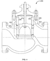
- FIG. 4 depicts an example fluid valve 400 having a spring element 402 positioned within a groove 404 between a cage retainer 406 and a cage 408.
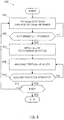
- FIG. 5 depicts a flow diagram representative of operations that may be performed to produce, for example, the example cage retainer 228 ( FIG. 2 ) or any other of the examples described herein.
- FIG. 5 depicts a flow diagram representative of operations that may be performed to produce, for example, the example cage retainer 228 ( FIG. 2 ) or any other of the examples described herein.
- FIG. 5 depicts a flow diagram representative of operations that may be performed to produce, for example, the example cage retainer 228 ( FIG. 2 ) or any other of the examples described herein.
- FIG. 5 depicts a flow diagram representative of operations that may be performed to produce, for example, the example cage retainer 228 ( FIG. 2 ) or any other of the examples described herein.
- FIG. 5 depicts a flow diagram representative of operations that may be performed to produce, for example, the example cage retainer 228 ( FIG. 2 ) or any other of the examples described herein.
- FIG. 5 depicts a flow diagram representative of operations that may be performed to produce,
- the exterior surface 248 of the cage retainer 228 ( FIG. 2 ) is machined (block 502) such that a diameter 264 of the cage retainer 228 ( FIG. 2 ) is substantially similar to a first diameter (e.g., a first predetermined diameter).
- a first diameter e.g., a first predetermined diameter
- the first diameter is relatively smaller than an inner diameter 266 of the bonnet 210 ( FIG. 2 ).
- the first diameter may have a diameter of approximately five millimeters less than the second diameter discussed below.
- the example method 500 determines whether or not the first diameter has been attained (block 504) (e.g., the diameter 264 of the cage retainer 228 ( FIG. 2 ) is substantially similar to the first diameter). If the example method 500 determines that the first diameter has not been attained, control returns to block 502. However, if the example method 500 determines that the first diameter has been attained, control advances to block 506. Alloy is then applied to the exterior surface 248 (block 506) of the cage retainer 228 ( FIG. 2 ) to form the plurality of projections 254 extending from the exterior surface 248, as shown in FIG. 6 , along a longitudinal axis 602 of the cage retainer 228.
- Alloy is then applied to the exterior surface 248 (block 506) of the cage retainer 228 ( FIG. 2 ) to form the plurality of projections 254 extending from the exterior surface 248, as shown in FIG. 6 , along a longitudinal axis 602 of the cage retainer 228.
- the example cage retainer 228 may include three (3) of the projections 254 evenly spaced about the exterior surface 248.
- the cage retainer 228 may include any number of the projections 254 that may be positioned about the exterior surface 248 in any suitable arrangement.
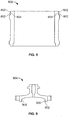
- a plurality of projections 802 may be a plurality of annular rings extending from an exterior surface 804 of a cage retainer 806. While the example depicted in FIG. 8 includes two projections, the example cage retainer 806 may include any number of projections (e.g., 1, 2, 3, 4, etc.).
- FIG. 8 may include any number of projections (e.g., 1, 2, 3, 4, etc.).
- an inner surface 902 of a bonnet 904 may be provided with a plurality of projections 906 as opposed to the exterior surface 248 of the cage retainer 228.
- the projections 906 may extend inwardly from the inner surface 902.
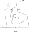
- a portion of the plurality of projections 254 may then be machined (block 508), as shown in FIG. 7 , such that a diameter of the cage retainer 228 ( FIG. 2 ) with the plurality of projections 254 is substantially similar to a second diameter (e.g., a second predetermined diameter).
- the second diameter corresponds to the inner diameter 266 of the bonnet 210.
- each of the plurality of projections 254 is elongated and may include a substantially rectangularly shaped surface 702 that is to at least partially contact the inner surface 250 of the bonnet 210.
- the example method 500 determines whether or not the second diameter has been attained (block 510) (e.g., the diameter of the cage retainer 228 ( FIG. 2 ) including the plurality of projections 254 is substantially similar to the second diameter). If the example method 500 determines that the second diameter has not been attained, control returns to block 508. However, if the example method 500 determines that the second diameter has been attained, control advances to block 512 and the example method 500 determines whether it should machine another cage retainer (block 512). Otherwise the example method 500 of FIG. 5 is ended.
- the second diameter e.g., the diameter of the cage retainer 228 ( FIG. 2 ) including the plurality of projections 254 is substantially similar to the second diameter.
Landscapes
- Engineering & Computer Science (AREA)
- General Engineering & Computer Science (AREA)
- Mechanical Engineering (AREA)
- Sliding Valves (AREA)
- Valve Housings (AREA)
- Lift Valve (AREA)
Claims (13)
- Fluidventil zur Steuerung einer Fluidströmung, umfassend:ein Ventilgehäuse (202), das einen Fluidströmungskanal (204) zwischen einer Einlassöffnung (206) und einer Auslassöffnung (208) definiert;einen Käfig (230), der in dem Fluidströmungskanal (204) angeordnet ist;eine Käfighalterung (228, 806), die innerhalb des Ventilkörpers (202) angeordnet ist, um in den Käfig (230) einzugreifen; ein mit dem Ventilkörper (202) gekoppeltes Ventiloberteil (210, 904); undeine dynamische Verbindung (252) zwischen einer Außenfläche (248, 804) der Käfighalterung (228, 806) und einer Innenfläche (250, 902) des Ventiloberteils (210, 904),wobei die dynamische Verbindung (252) verhindert, dass die Käfighalterung (228, 806) am Oberteil fixiert wird (210, 904), undwobei die dynamische Verbindung (252) eine Vielzahl von beabstandeten Vorsprüngen (254, 802, 906) umfasst, die zwischen der Innenfläche (250, 902) des Ventiloberteils (210, 904) und der Außenfläche (248, 804) der Käfighalterung (228, 806) positioniert sind, um einen kontinuierlichen Eingriff zwischen der Außenfläche (248, 804) der Käfighalterung (228, 806) und der Innenfläche des Ventiloberteils (210, 904) zu verhindern;dadurch gekennzeichnet, dassdie Käfighalterung (228, 806) ein erstes Material aufweist und jede der Vielzahl von Vorsprüngen (254, 802, 906) ein zweites Material aufweist, das sich vom ersten Material unterscheidet.
- Fluidventil nach Anspruch 1, wobei die Käfighalterung (228, 806) die Vorsprünge umfasst (254, 802, 906), und die Vorsprünge (254, 802, 906) von der Außenfläche (248, 804) des Käfighalters vorstehen (228, 806).
- Fluidventil nach Anspruch 2, wobei mindestens einer der Vorsprünge (254) eine längliche Form aufweist, die sich entlang einer Längsachse (602) der Käfighalterung (228, 806) erstreckt.
- Fluidventil nach einem der vorangegangenen Ansprüche, wobei die Vorsprünge (254, 802, 906) radial um die Außenfläche (248, 804) beabstandet sind.
- Fluidventil nach Anspruch 2, wobei mindestens einer der Vorsprünge (254) einen ringförmigen Ring (802) aufweist.
- Fluidventil nach einem der Ansprüche 2 bis 5, wobei die Außenfläche (248, 804) der Käfighalterung (228, 806) einen ersten Durchmesser (264) hat, die Vorsprünge (254, 802, 906) einen zweiten Durchmesser definieren, und der zweite Durchmesser größer ist als der erste Durchmesser.
- Fluidventil nach Anspruch 6, wobei der zweite Durchmesser einem inneren Durchmesser (266) des Ventiloberteils (210, 904) entspricht.
- Fluidventil nach Anspruch 7, wobei das erste Material aus einem Stahlmaterial und das zweite Material aus einem Kobaltlegierungsmaterial besteht.
- Fluidventil nach Anspruch 1, wobei das Ventiloberteil (210, 904) die Vorsprünge (906) umfasst, die von der Innenfläche (250, 902) des Ventiloberteils (210, 904) nach innen vorstehen.
- Fluidventil nach einem der vorhergehenden Ansprüche, wobei der Käfig (230) zum Führen eines Verschlußelements des Fluidventils angeordnet ist.
- Fluidventil nach einem der vorhergehenden Ansprüche, wobei der Käfig (230) koaxial zur Käfighalterung (228, 806) ausgerichtet ist.
- Verfahren zur Herstellung einer Käfighalterung (228, 806) und eines Ventiloberteils (210, 904) zur Verwendung mit einem Fluidventil, wobei das Ventiloberteil (210, 904) eine Innenfläche (250, 902) aufweist, die einen Innendurchmesser definiert, wobei das Verfahren umfasst:Zerspanen eines Außenabschnitts der Käfighalterung (228, 806), um einen ersten Durchmesser zu erhalten;Aufbringen einer Legierung auf eine Oberfläche des Außenabschnitts, um die Oberfläche mit einer Vielzahl von Vorsprüngen (254, 802, 906) zu versehen, die von der Oberfläche vorstehen und radial um diese herum beabstandet sind; undZerspanung eines Abschnitts der Legierung, so dass die Vielzahl von Vorsprüngen (254, 802, 906) einen zweiten Durchmesser aufweist, der dem Innendurchmesser des Ventiloberteils (210, 904) entspricht, wobei der zweite Durchmesser größer als der erste Durchmesser (264) ist, um einen kontinuierlichen Eingriff zwischen der Oberfläche des Außenabschnitts und einer Innenfläche (250, 902) des Ventiloberteils (210, 904) zu verhindern.
- Verfahren nach Anspruch 12, wobei der erste Schritt des Zerspanens das Zerspanen des ersten Durchmessers (264) umfasst, so dass er kleiner als der Innendurchmesser des Ventiloberteils (210, 904) ist.
Applications Claiming Priority (2)
| Application Number | Priority Date | Filing Date | Title |
|---|---|---|---|
| US12/480,425 US8356622B2 (en) | 2009-06-08 | 2009-06-08 | Fluid valves having dynamic valve trim joints |
| PCT/US2010/033762 WO2010144193A1 (en) | 2009-06-08 | 2010-05-05 | Fluid valves having dynamic valve trim joints |
Publications (2)
| Publication Number | Publication Date |
|---|---|
| EP2440819A1 EP2440819A1 (de) | 2012-04-18 |
| EP2440819B1 true EP2440819B1 (de) | 2019-04-10 |
Family
ID=42710815
Family Applications (1)
| Application Number | Title | Priority Date | Filing Date |
|---|---|---|---|
| EP10717433.6A Active EP2440819B1 (de) | 2009-06-08 | 2010-05-05 | Flüssigkeitsventile mit dynamischen ventilgarniturverbindungen |
Country Status (11)
| Country | Link |
|---|---|
| US (1) | US8356622B2 (de) |
| EP (1) | EP2440819B1 (de) |
| JP (1) | JP5657650B2 (de) |
| CN (1) | CN102459974B (de) |
| AU (1) | AU2010259183B2 (de) |
| BR (1) | BRPI1013058A2 (de) |
| CA (1) | CA2764803C (de) |
| MX (1) | MX2011013163A (de) |
| NO (1) | NO342482B1 (de) |
| RU (1) | RU2542726C2 (de) |
| WO (1) | WO2010144193A1 (de) |
Families Citing this family (13)
| Publication number | Priority date | Publication date | Assignee | Title |
|---|---|---|---|---|
| US9046191B2 (en) | 2012-08-30 | 2015-06-02 | Fisher Controls International, Llc | Valve body with upper flow diverter |
| CN202972080U (zh) * | 2012-10-22 | 2013-06-05 | 费希尔久安输配设备(成都)有限公司 | 一种阀组件 |
| RU2661997C2 (ru) * | 2013-01-28 | 2018-07-23 | Эмерсон Процесс Менеджмент Регьюлэйтор Текнолоджиз, Инк. | Поршневой узел и использующий его регулятор давления |
| JP6163129B2 (ja) * | 2014-03-31 | 2017-07-12 | アズビル株式会社 | ケージ弁 |
| DE102015011551B3 (de) * | 2015-09-02 | 2017-03-02 | Samson Aktiengesellschaft | Stellventil zum Steuern einer Fluidströmung einer prozesstechnischen Anlage |
| US10663083B2 (en) * | 2016-10-21 | 2020-05-26 | Fisher Controls International Llc | Trim assembly having a side branch resonator array and fluid control valve comprising same |
| DE102017123396A1 (de) * | 2017-10-09 | 2019-04-11 | Samson Aktiengesellschaft | Hubventil und Anordnung für ein Hubventil |
| RU2717731C1 (ru) * | 2019-07-15 | 2020-03-25 | Ирина Александровна Анкудинова | Дроссель регулируемый |
| CN110598301B (zh) * | 2019-09-05 | 2022-10-11 | 华北电力科学研究院有限责任公司 | 液化空气储能系统参数耦合设计方法 |
| US11407070B2 (en) * | 2020-12-14 | 2022-08-09 | Fisher Controls International Llc | Bonnet and valve trim assembly and related methods |
| US11946565B2 (en) * | 2021-02-25 | 2024-04-02 | Hayward Industries, Inc. | Valve assembly |
| US11808378B2 (en) * | 2021-04-13 | 2023-11-07 | Michael Pellegrini | Globe valve assembly |
| CN114704662A (zh) * | 2022-04-07 | 2022-07-05 | 江苏亿阀股份有限公司 | 一种高压抗静电氧气用截止阀及其使用方法 |
Family Cites Families (28)
| Publication number | Priority date | Publication date | Assignee | Title |
|---|---|---|---|---|
| US10028A (en) * | 1853-09-20 | Improvement in razor-strops | ||
| US3019A (en) * | 1843-03-30 | Hatching chickens | ||
| US6004A (en) * | 1849-01-09 | chinnqck | ||
| NL137883C (de) | 1967-09-11 | |||
| JPS4634955Y1 (de) * | 1970-06-12 | 1971-12-02 | ||
| US3742984A (en) * | 1971-09-02 | 1973-07-03 | Acf Ind Inc | Globe valve having hydraulic balancing |
| US3834666A (en) * | 1972-10-02 | 1974-09-10 | Masoneilan Int Inc | Control valve with elastically loaded cage trim |
| JPS5398430U (de) * | 1977-01-13 | 1978-08-10 | ||
| US4149563A (en) * | 1977-02-16 | 1979-04-17 | Copes-Vulcan, Inc. | Anti-cavitation valve |
| SU934130A1 (ru) * | 1980-08-28 | 1982-06-07 | Предприятие П/Я А-7755 | Задвижка |
| US4542879A (en) * | 1981-11-27 | 1985-09-24 | Marbor Engineering Associates | Valve ring arrangements in metallic valves, control valves, condensate removal devices, and other means for the prevention of leakages due to corrosion |
| JPS617672U (ja) * | 1984-06-20 | 1986-01-17 | トキコ株式会社 | 弁装置 |
| US5012841A (en) * | 1989-08-24 | 1991-05-07 | Keystone International Holdings Corp. | Pressure reducing and conditioning valves |
| US5492146A (en) * | 1992-09-02 | 1996-02-20 | Richards Industries, Inc. | Pressure regulators |
| JPH10132177A (ja) * | 1996-10-28 | 1998-05-22 | Sekisui Chem Co Ltd | 管端インサート |
| JP2000273573A (ja) * | 1999-03-26 | 2000-10-03 | Hitachi Ltd | 耐蝕・耐摩耗合金とその合金を用いた機器 |
| JP2001333995A (ja) * | 2000-05-30 | 2001-12-04 | Senju Sprinkler Kk | 一斉開放弁の弁体ガイド機構及び一斉開放弁 |
| JP2002089722A (ja) * | 2000-09-13 | 2002-03-27 | Tokico Ltd | 圧力制御弁 |
| US6641110B1 (en) * | 2002-04-22 | 2003-11-04 | Nhan V. Nguyen | Binary balance seal assembly |
| JP4158596B2 (ja) * | 2003-05-08 | 2008-10-01 | 株式会社ジェイテクト | ステアリング装置 |
| US6932321B2 (en) * | 2003-05-28 | 2005-08-23 | Fisher Controls International Llc | Balanced-plug cage style control valve and bonnet seal assembly |
| US6997211B2 (en) * | 2003-07-03 | 2006-02-14 | Fisher Controls International Llc. | Multiple material valve plug for high temperature operation |
| JP2005076765A (ja) * | 2003-09-01 | 2005-03-24 | Unisia Jkc Steering System Co Ltd | 逆止弁及びその製造方法 |
| US20050151107A1 (en) * | 2003-12-29 | 2005-07-14 | Jianchao Shu | Fluid control system and stem joint |
| US20060049375A1 (en) * | 2004-09-07 | 2006-03-09 | Fisher Controls International Llc | Boronized valve seal |
| RU2298128C2 (ru) * | 2005-06-06 | 2007-04-27 | Открытое акционерное общество "НПО "Промавтоматика" | Клапан запорно-регулирующий |
| GB0618165D0 (en) | 2006-09-15 | 2006-10-25 | Imi Vision Ltd | Improvements in fluid control |
| DK2385212T3 (en) | 2007-09-26 | 2018-02-19 | Cameron Int Corp | THROTTLE VALVE COLLECTION |
-
2009
- 2009-06-08 US US12/480,425 patent/US8356622B2/en active Active
-
2010
- 2010-05-05 AU AU2010259183A patent/AU2010259183B2/en not_active Ceased
- 2010-05-05 JP JP2012513953A patent/JP5657650B2/ja not_active Expired - Fee Related
- 2010-05-05 WO PCT/US2010/033762 patent/WO2010144193A1/en active Application Filing
- 2010-05-05 CA CA2764803A patent/CA2764803C/en active Active
- 2010-05-05 MX MX2011013163A patent/MX2011013163A/es active IP Right Grant
- 2010-05-05 CN CN201080025321.7A patent/CN102459974B/zh active Active
- 2010-05-05 RU RU2011152814/06A patent/RU2542726C2/ru active
- 2010-05-05 BR BRPI1013058A patent/BRPI1013058A2/pt not_active Application Discontinuation
- 2010-05-05 EP EP10717433.6A patent/EP2440819B1/de active Active
-
2011
- 2011-12-06 NO NO20111684A patent/NO342482B1/no not_active IP Right Cessation
Non-Patent Citations (1)
| Title |
|---|
| None * |
Also Published As
| Publication number | Publication date |
|---|---|
| NO20111684A1 (no) | 2011-12-06 |
| NO342482B1 (no) | 2018-05-28 |
| WO2010144193A1 (en) | 2010-12-16 |
| CA2764803C (en) | 2016-08-09 |
| EP2440819A1 (de) | 2012-04-18 |
| MX2011013163A (es) | 2012-01-30 |
| RU2542726C2 (ru) | 2015-02-27 |
| CN102459974A (zh) | 2012-05-16 |
| JP5657650B2 (ja) | 2015-01-21 |
| AU2010259183B2 (en) | 2016-02-25 |
| BRPI1013058A2 (pt) | 2016-04-05 |
| US20100307610A1 (en) | 2010-12-09 |
| CN102459974B (zh) | 2014-07-16 |
| CA2764803A1 (en) | 2010-12-16 |
| JP2012529599A (ja) | 2012-11-22 |
| RU2011152814A (ru) | 2013-07-20 |
| AU2010259183A1 (en) | 2011-12-15 |
| US8356622B2 (en) | 2013-01-22 |
Similar Documents
| Publication | Publication Date | Title |
|---|---|---|
| EP2440819B1 (de) | Flüssigkeitsventile mit dynamischen ventilgarniturverbindungen | |
| US8720854B2 (en) | Floating ball valve seal with dynamic C-seal and static C-seal | |
| EP2282093B1 (de) | Steuerventil mit einer C-Dichtung | |
| JP5511673B2 (ja) | 流量制御装置および流量制御装置を組み立てるための方法 | |
| EP2240716B1 (de) | Dichtungsanordnung eines ventils mit einem zweiteiligen ventileinsatz | |
| EP2733402B1 (de) | Druckausgeglichene federbelastete Überfahrzeitabdichtungsvorrichtung | |
| US10533668B2 (en) | Seal assemblies for use with fluid valves | |
| MX2011012617A (es) | Aparato para asiento de valvula, para uso con valvulas para fluidos. | |
| EP3658806B1 (de) | Dichtungsanordnungen für flüssigkeitsventile | |
| US11287057B2 (en) | Y-globe valve assembly with integrated pressure relief passageway | |
| US11852262B2 (en) | Heat tracing systems for fluid valves and related methods | |
| WO2023186926A1 (en) | Device for controlling passage of fluid |
Legal Events
| Date | Code | Title | Description |
|---|---|---|---|
| PUAI | Public reference made under article 153(3) epc to a published international application that has entered the european phase |
Free format text: ORIGINAL CODE: 0009012 |
|
| 17P | Request for examination filed |
Effective date: 20111206 |
|
| AK | Designated contracting states |
Kind code of ref document: A1 Designated state(s): AL AT BE BG CH CY CZ DE DK EE ES FI FR GB GR HR HU IE IS IT LI LT LU LV MC MK MT NL NO PL PT RO SE SI SK SM TR |
|
| DAX | Request for extension of the european patent (deleted) | ||
| 17Q | First examination report despatched |
Effective date: 20151104 |
|
| STAA | Information on the status of an ep patent application or granted ep patent |
Free format text: STATUS: EXAMINATION IS IN PROGRESS |
|
| GRAP | Despatch of communication of intention to grant a patent |
Free format text: ORIGINAL CODE: EPIDOSNIGR1 |
|
| STAA | Information on the status of an ep patent application or granted ep patent |
Free format text: STATUS: GRANT OF PATENT IS INTENDED |
|
| INTG | Intention to grant announced |
Effective date: 20181031 |
|
| GRAS | Grant fee paid |
Free format text: ORIGINAL CODE: EPIDOSNIGR3 |
|
| GRAA | (expected) grant |
Free format text: ORIGINAL CODE: 0009210 |
|
| STAA | Information on the status of an ep patent application or granted ep patent |
Free format text: STATUS: THE PATENT HAS BEEN GRANTED |
|
| AK | Designated contracting states |
Kind code of ref document: B1 Designated state(s): AL AT BE BG CH CY CZ DE DK EE ES FI FR GB GR HR HU IE IS IT LI LT LU LV MC MK MT NL NO PL PT RO SE SI SK SM TR |
|
| REG | Reference to a national code |
Ref country code: GB Ref legal event code: FG4D |
|
| REG | Reference to a national code |
Ref country code: CH Ref legal event code: EP Ref country code: AT Ref legal event code: REF Ref document number: 1119122 Country of ref document: AT Kind code of ref document: T Effective date: 20190415 |
|
| REG | Reference to a national code |
Ref country code: DE Ref legal event code: R096 Ref document number: 602010058134 Country of ref document: DE |
|
| REG | Reference to a national code |
Ref country code: IE Ref legal event code: FG4D |
|
| REG | Reference to a national code |
Ref country code: NL Ref legal event code: MP Effective date: 20190410 |
|
| REG | Reference to a national code |
Ref country code: LT Ref legal event code: MG4D |
|
| REG | Reference to a national code |
Ref country code: AT Ref legal event code: MK05 Ref document number: 1119122 Country of ref document: AT Kind code of ref document: T Effective date: 20190410 |
|
| PG25 | Lapsed in a contracting state [announced via postgrant information from national office to epo] |
Ref country code: NL Free format text: LAPSE BECAUSE OF FAILURE TO SUBMIT A TRANSLATION OF THE DESCRIPTION OR TO PAY THE FEE WITHIN THE PRESCRIBED TIME-LIMIT Effective date: 20190410 |
|
| PG25 | Lapsed in a contracting state [announced via postgrant information from national office to epo] |
Ref country code: AL Free format text: LAPSE BECAUSE OF FAILURE TO SUBMIT A TRANSLATION OF THE DESCRIPTION OR TO PAY THE FEE WITHIN THE PRESCRIBED TIME-LIMIT Effective date: 20190410 Ref country code: ES Free format text: LAPSE BECAUSE OF FAILURE TO SUBMIT A TRANSLATION OF THE DESCRIPTION OR TO PAY THE FEE WITHIN THE PRESCRIBED TIME-LIMIT Effective date: 20190410 Ref country code: SE Free format text: LAPSE BECAUSE OF FAILURE TO SUBMIT A TRANSLATION OF THE DESCRIPTION OR TO PAY THE FEE WITHIN THE PRESCRIBED TIME-LIMIT Effective date: 20190410 Ref country code: HR Free format text: LAPSE BECAUSE OF FAILURE TO SUBMIT A TRANSLATION OF THE DESCRIPTION OR TO PAY THE FEE WITHIN THE PRESCRIBED TIME-LIMIT Effective date: 20190410 Ref country code: NO Free format text: LAPSE BECAUSE OF FAILURE TO SUBMIT A TRANSLATION OF THE DESCRIPTION OR TO PAY THE FEE WITHIN THE PRESCRIBED TIME-LIMIT Effective date: 20190710 Ref country code: PT Free format text: LAPSE BECAUSE OF FAILURE TO SUBMIT A TRANSLATION OF THE DESCRIPTION OR TO PAY THE FEE WITHIN THE PRESCRIBED TIME-LIMIT Effective date: 20190910 Ref country code: LT Free format text: LAPSE BECAUSE OF FAILURE TO SUBMIT A TRANSLATION OF THE DESCRIPTION OR TO PAY THE FEE WITHIN THE PRESCRIBED TIME-LIMIT Effective date: 20190410 Ref country code: FI Free format text: LAPSE BECAUSE OF FAILURE TO SUBMIT A TRANSLATION OF THE DESCRIPTION OR TO PAY THE FEE WITHIN THE PRESCRIBED TIME-LIMIT Effective date: 20190410 |
|
| PG25 | Lapsed in a contracting state [announced via postgrant information from national office to epo] |
Ref country code: PL Free format text: LAPSE BECAUSE OF FAILURE TO SUBMIT A TRANSLATION OF THE DESCRIPTION OR TO PAY THE FEE WITHIN THE PRESCRIBED TIME-LIMIT Effective date: 20190410 Ref country code: LV Free format text: LAPSE BECAUSE OF FAILURE TO SUBMIT A TRANSLATION OF THE DESCRIPTION OR TO PAY THE FEE WITHIN THE PRESCRIBED TIME-LIMIT Effective date: 20190410 Ref country code: BG Free format text: LAPSE BECAUSE OF FAILURE TO SUBMIT A TRANSLATION OF THE DESCRIPTION OR TO PAY THE FEE WITHIN THE PRESCRIBED TIME-LIMIT Effective date: 20190710 Ref country code: GR Free format text: LAPSE BECAUSE OF FAILURE TO SUBMIT A TRANSLATION OF THE DESCRIPTION OR TO PAY THE FEE WITHIN THE PRESCRIBED TIME-LIMIT Effective date: 20190711 |
|
| REG | Reference to a national code |
Ref country code: DE Ref legal event code: R119 Ref document number: 602010058134 Country of ref document: DE |
|
| REG | Reference to a national code |
Ref country code: CH Ref legal event code: PL |
|
| PG25 | Lapsed in a contracting state [announced via postgrant information from national office to epo] |
Ref country code: IS Free format text: LAPSE BECAUSE OF FAILURE TO SUBMIT A TRANSLATION OF THE DESCRIPTION OR TO PAY THE FEE WITHIN THE PRESCRIBED TIME-LIMIT Effective date: 20190810 Ref country code: AT Free format text: LAPSE BECAUSE OF FAILURE TO SUBMIT A TRANSLATION OF THE DESCRIPTION OR TO PAY THE FEE WITHIN THE PRESCRIBED TIME-LIMIT Effective date: 20190410 |
|
| PG25 | Lapsed in a contracting state [announced via postgrant information from national office to epo] |
Ref country code: MC Free format text: LAPSE BECAUSE OF FAILURE TO SUBMIT A TRANSLATION OF THE DESCRIPTION OR TO PAY THE FEE WITHIN THE PRESCRIBED TIME-LIMIT Effective date: 20190410 Ref country code: CH Free format text: LAPSE BECAUSE OF NON-PAYMENT OF DUE FEES Effective date: 20190531 Ref country code: LI Free format text: LAPSE BECAUSE OF NON-PAYMENT OF DUE FEES Effective date: 20190531 Ref country code: DK Free format text: LAPSE BECAUSE OF FAILURE TO SUBMIT A TRANSLATION OF THE DESCRIPTION OR TO PAY THE FEE WITHIN THE PRESCRIBED TIME-LIMIT Effective date: 20190410 Ref country code: SK Free format text: LAPSE BECAUSE OF FAILURE TO SUBMIT A TRANSLATION OF THE DESCRIPTION OR TO PAY THE FEE WITHIN THE PRESCRIBED TIME-LIMIT Effective date: 20190410 Ref country code: EE Free format text: LAPSE BECAUSE OF FAILURE TO SUBMIT A TRANSLATION OF THE DESCRIPTION OR TO PAY THE FEE WITHIN THE PRESCRIBED TIME-LIMIT Effective date: 20190410 Ref country code: RO Free format text: LAPSE BECAUSE OF FAILURE TO SUBMIT A TRANSLATION OF THE DESCRIPTION OR TO PAY THE FEE WITHIN THE PRESCRIBED TIME-LIMIT Effective date: 20190410 Ref country code: CZ Free format text: LAPSE BECAUSE OF FAILURE TO SUBMIT A TRANSLATION OF THE DESCRIPTION OR TO PAY THE FEE WITHIN THE PRESCRIBED TIME-LIMIT Effective date: 20190410 |
|
| REG | Reference to a national code |
Ref country code: BE Ref legal event code: MM Effective date: 20190531 |
|
| PLBE | No opposition filed within time limit |
Free format text: ORIGINAL CODE: 0009261 |
|
| STAA | Information on the status of an ep patent application or granted ep patent |
Free format text: STATUS: NO OPPOSITION FILED WITHIN TIME LIMIT |
|
| PG25 | Lapsed in a contracting state [announced via postgrant information from national office to epo] |
Ref country code: LU Free format text: LAPSE BECAUSE OF NON-PAYMENT OF DUE FEES Effective date: 20190505 Ref country code: IT Free format text: LAPSE BECAUSE OF FAILURE TO SUBMIT A TRANSLATION OF THE DESCRIPTION OR TO PAY THE FEE WITHIN THE PRESCRIBED TIME-LIMIT Effective date: 20190410 Ref country code: SM Free format text: LAPSE BECAUSE OF FAILURE TO SUBMIT A TRANSLATION OF THE DESCRIPTION OR TO PAY THE FEE WITHIN THE PRESCRIBED TIME-LIMIT Effective date: 20190410 |
|
| 26N | No opposition filed |
Effective date: 20200113 |
|
| PG25 | Lapsed in a contracting state [announced via postgrant information from national office to epo] |
Ref country code: TR Free format text: LAPSE BECAUSE OF FAILURE TO SUBMIT A TRANSLATION OF THE DESCRIPTION OR TO PAY THE FEE WITHIN THE PRESCRIBED TIME-LIMIT Effective date: 20190410 |
|
| PG25 | Lapsed in a contracting state [announced via postgrant information from national office to epo] |
Ref country code: IE Free format text: LAPSE BECAUSE OF NON-PAYMENT OF DUE FEES Effective date: 20190505 Ref country code: DE Free format text: LAPSE BECAUSE OF NON-PAYMENT OF DUE FEES Effective date: 20191203 |
|
| PG25 | Lapsed in a contracting state [announced via postgrant information from national office to epo] |
Ref country code: BE Free format text: LAPSE BECAUSE OF NON-PAYMENT OF DUE FEES Effective date: 20190531 Ref country code: SI Free format text: LAPSE BECAUSE OF FAILURE TO SUBMIT A TRANSLATION OF THE DESCRIPTION OR TO PAY THE FEE WITHIN THE PRESCRIBED TIME-LIMIT Effective date: 20190410 |
|
| PG25 | Lapsed in a contracting state [announced via postgrant information from national office to epo] |
Ref country code: CY Free format text: LAPSE BECAUSE OF FAILURE TO SUBMIT A TRANSLATION OF THE DESCRIPTION OR TO PAY THE FEE WITHIN THE PRESCRIBED TIME-LIMIT Effective date: 20190410 |
|
| PG25 | Lapsed in a contracting state [announced via postgrant information from national office to epo] |
Ref country code: HU Free format text: LAPSE BECAUSE OF FAILURE TO SUBMIT A TRANSLATION OF THE DESCRIPTION OR TO PAY THE FEE WITHIN THE PRESCRIBED TIME-LIMIT; INVALID AB INITIO Effective date: 20100505 Ref country code: MT Free format text: LAPSE BECAUSE OF FAILURE TO SUBMIT A TRANSLATION OF THE DESCRIPTION OR TO PAY THE FEE WITHIN THE PRESCRIBED TIME-LIMIT Effective date: 20190410 |
|
| PG25 | Lapsed in a contracting state [announced via postgrant information from national office to epo] |
Ref country code: MK Free format text: LAPSE BECAUSE OF FAILURE TO SUBMIT A TRANSLATION OF THE DESCRIPTION OR TO PAY THE FEE WITHIN THE PRESCRIBED TIME-LIMIT Effective date: 20190410 |
|
| P01 | Opt-out of the competence of the unified patent court (upc) registered |
Effective date: 20230526 |
|
| PGFP | Annual fee paid to national office [announced via postgrant information from national office to epo] |
Ref country code: GB Payment date: 20240419 Year of fee payment: 15 |
|
| PGFP | Annual fee paid to national office [announced via postgrant information from national office to epo] |
Ref country code: FR Payment date: 20240418 Year of fee payment: 15 |