EP2169313B1 - Kraftstofflanze für eine Gasturbinenanlage - Google Patents
Kraftstofflanze für eine Gasturbinenanlage Download PDFInfo
- Publication number
- EP2169313B1 EP2169313B1 EP09171054.1A EP09171054A EP2169313B1 EP 2169313 B1 EP2169313 B1 EP 2169313B1 EP 09171054 A EP09171054 A EP 09171054A EP 2169313 B1 EP2169313 B1 EP 2169313B1
- Authority
- EP
- European Patent Office
- Prior art keywords
- fuel
- lance
- combustor
- gas flow
- outlets
- Prior art date
- Legal status (The legal status is an assumption and is not a legal conclusion. Google has not performed a legal analysis and makes no representation as to the accuracy of the status listed.)
- Not-in-force
Links
- 239000000446 fuel Substances 0.000 title claims description 146
- 239000007789 gas Substances 0.000 claims description 46
- 230000015572 biosynthetic process Effects 0.000 claims description 20
- 238000002485 combustion reaction Methods 0.000 claims description 16
- UFHFLCQGNIYNRP-UHFFFAOYSA-N Hydrogen Chemical compound [H][H] UFHFLCQGNIYNRP-UHFFFAOYSA-N 0.000 claims description 7
- 239000001257 hydrogen Substances 0.000 claims description 7
- 229910052739 hydrogen Inorganic materials 0.000 claims description 7
- 238000007254 oxidation reaction Methods 0.000 description 19
- 238000005755 formation reaction Methods 0.000 description 18
- 239000000567 combustion gas Substances 0.000 description 7
- 238000011144 upstream manufacturing Methods 0.000 description 7
- VNWKTOKETHGBQD-UHFFFAOYSA-N methane Chemical compound C VNWKTOKETHGBQD-UHFFFAOYSA-N 0.000 description 6
- 230000000694 effects Effects 0.000 description 5
- 239000003345 natural gas Substances 0.000 description 3
- 239000000203 mixture Substances 0.000 description 2
- 230000002028 premature Effects 0.000 description 2
- 230000004323 axial length Effects 0.000 description 1
- 230000000295 complement effect Effects 0.000 description 1
- 238000001816 cooling Methods 0.000 description 1
- 230000001419 dependent effect Effects 0.000 description 1
- 230000002708 enhancing effect Effects 0.000 description 1
- 238000002347 injection Methods 0.000 description 1
- 239000007924 injection Substances 0.000 description 1
- 238000000034 method Methods 0.000 description 1
- 238000012986 modification Methods 0.000 description 1
- 230000004048 modification Effects 0.000 description 1
- 230000003647 oxidation Effects 0.000 description 1
- 230000035515 penetration Effects 0.000 description 1
- 230000001737 promoting effect Effects 0.000 description 1
Images
Classifications
-
- F—MECHANICAL ENGINEERING; LIGHTING; HEATING; WEAPONS; BLASTING
- F23—COMBUSTION APPARATUS; COMBUSTION PROCESSES
- F23R—GENERATING COMBUSTION PRODUCTS OF HIGH PRESSURE OR HIGH VELOCITY, e.g. GAS-TURBINE COMBUSTION CHAMBERS
- F23R3/00—Continuous combustion chambers using liquid or gaseous fuel
- F23R3/28—Continuous combustion chambers using liquid or gaseous fuel characterised by the fuel supply
-
- F—MECHANICAL ENGINEERING; LIGHTING; HEATING; WEAPONS; BLASTING
- F23—COMBUSTION APPARATUS; COMBUSTION PROCESSES
- F23C—METHODS OR APPARATUS FOR COMBUSTION USING FLUID FUEL OR SOLID FUEL SUSPENDED IN A CARRIER GAS OR AIR
- F23C2900/00—Special features of, or arrangements for combustion apparatus using fluid fuels or solid fuels suspended in air; Combustion processes therefor
- F23C2900/07021—Details of lances
-
- F—MECHANICAL ENGINEERING; LIGHTING; HEATING; WEAPONS; BLASTING
- F23—COMBUSTION APPARATUS; COMBUSTION PROCESSES
- F23C—METHODS OR APPARATUS FOR COMBUSTION USING FLUID FUEL OR SOLID FUEL SUSPENDED IN A CARRIER GAS OR AIR
- F23C2900/00—Special features of, or arrangements for combustion apparatus using fluid fuels or solid fuels suspended in air; Combustion processes therefor
- F23C2900/99011—Combustion process using synthetic gas as a fuel, i.e. a mixture of CO and H2
-
- F—MECHANICAL ENGINEERING; LIGHTING; HEATING; WEAPONS; BLASTING
- F23—COMBUSTION APPARATUS; COMBUSTION PROCESSES
- F23R—GENERATING COMBUSTION PRODUCTS OF HIGH PRESSURE OR HIGH VELOCITY, e.g. GAS-TURBINE COMBUSTION CHAMBERS
- F23R2900/00—Special features of, or arrangements for continuous combustion chambers; Combustion processes therefor
- F23R2900/03341—Sequential combustion chambers or burners
Definitions
- the present invention relates to a fuel lance for introducing fuel into a gas flow in a combustor of a gas turbine engine, in particular a gas turbine with sequential combustion.
- a gas turbine with sequential combustion is known to improve the efficiency of a gas turbine. This is achieved by increasing the turbine inlet temperature.
- fuel is combusted in a first combustor and the hot combustion gases are passed through a first turbine and subsequently supplied to a second combustor known as an SEV combustor into which fuel is introduced.
- the combustion of the hot gases is completed in the SEV combustor and the combustion gases are subsequently supplied to a second turbine.
- a hydrogen rich fuel such as MBTU
- Radially injecting a hydrogen rich fuel, such as MBTU into an oncoming oxidization stream is problematic due to the blockage effect of the fuel jets (i.e. the stagnation zone upstream of the jet where the oncoming air stagnates) increasing local residence times of the fuel and promoting auto ignition.
- the shear stresses are highest for a fuel jet perpendicular to the main flow and the resulting turbulence may be high enough to permit upstream propagation of the flame.
- the present invention addresses these problems.
- the present invention aims to provide a fuel lance for introducing fuel into a gas flow in a combustor of a gas turbine engine which improves the mixing of the fuel with the gas flow and hence increasing efficiency whilst reducing emissions.
- a region of the fuel lance through which the fuel is introduced into the gas flow comprises a helical formation.
- the helical formation in the region where fuel is introduced into the gas flow imparts swirl to the fuel thereby enhancing the mixing of the fuel with the gas flow.
- the helical formation comprises a helical groove on the outer surface of the lance extending generally in the axial direction of the lance.
- a plurality of fuel outlets are arranged on the surface of the helical groove and spaced apart in the axial and/or radial directions.
- a plurality of smaller fuel jets spaced apart in the axial and/or radial directions in combination with a helical groove imparting a circumferential component to the fuel jet improves the mixing of the fuel with the gas flow.
- the fuel diameter is chosen appropriately to get the desired momentum and jet penetration.
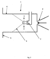
- FIG. 2 shows schematically a state of the art combustion chamber 1 of a gas turbine engine.
- the combustion chamber is an SEV combustor forming part of a gas turbine with sequential combustion, whereby fuel is combusted in a first combustor and the hot combustion gases are passed through a first turbine and subsequently supplied to a second combustor known as an SEV combustor 1 into which fuel is introduced.
- the hot combustion gases are introduced into the SEV combustor 1 through a vortex generator or generators 2.
- the combustion gases contain enough oxidation gases for further combustion in the SEV combustor.
- the SEV combustor 1 comprises a fuel lance 7 projecting into the SEV combustor 1 for introducing fuel into the combustor 1.
- Fuel is injected radially (designated by arrow 3) from holes in the lance into the oxidization stream and interacts with the vortex/vortices created by the vortex generator 2.
- a hydrogen rich fuel such as MBTU
- the fuel reaches the wall 4 of the combustor far upstream of the combustion front panel 5 as indicated by the dotted line 6 (in front of the dotted line represents a fuel air mixture whereas behind the dotted line represents the oxidization gas only).
- the presence of fuel near the wall 4 promotes auto ignition (i.e. premature ignition).
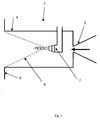
- FIG. 1 shows schematically a combustor 1 of a gas turbine system.
- the combustion chamber may be an SEV combustor 1 forming part of a gas turbine with sequential combustion, whereby fuel is combusted in a first combustor and the hot combustion gases are passed through a first turbine and subsequently supplied to a second combustor known as an SEV combustor 1 into which fuel is introduced.
- the oxidization gases being introduced into the SEV combustor 1 through a vortex generator or generators 2.
- the fuel lance 7 according to the invention is provided for introducing fuel into the combustor.
- the fuel lance 7 is designed to provide for better mixing of the fuel with the oxidization gas.
- the fuel lance 7 of the invention is also formed so as to prevent the fuel from reaching the wall 4 of the combustor 1 upstream of the combustion front panel 5 therefore avoiding auto ignition.
- the dotted line 6 once more representing the border between the upstream oxidization gas only area and the downstream fuel and oxidization gas mixture.
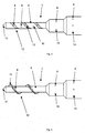
- FIG. 3 shows one embodiment of a fuel lance 7 according to the invention.
- the fuel lance has fuel injector outlets 8.
- the fuel lance 7 is provided according to the invention with a helical or spiral formation 12.
- the helical or spiral formation 12 is arranged in a region of the lance where the fuel outlets 8 a situated.
- the helical formation is in the form of a groove 13 on the outer surface 9 of the fuel lance.
- At least one fuel outlet 8 is arranged in the groove 13.
- a series of fuel outlets 8 are arranged in the groove 13 and spaced in the axial direction.
- the fuel outlets 8 can also be arranged to be spaced in the circumferential directions.
- a series of smaller fuel injector outlets 8 provide a better fuel distributed than few larger fuel injector outlets.
- the fuel injector outlets 8 which are arranged on the surface of the helical groove 13 may be directed in a radial and/or axial directions.
- the fuel injector outlets 8 arranged on the surface of the helical groove 13 may also be directed in the direction of the groove i.e. they could have an axial, radial and circumferential/tangential component relative to the centre axis of the fuel lance 7.
- the helical formation improves the mixing of the fuel with the oxidization flow in the circumferential direction. This combined with the vortex flow of the oxidization gas from the vortex generator 2 leads to a superior mixing effect.
- the spread of the fuel is also controlled by the swirl imparted to the fuel thus improving flashback safety and reducing harmful emissions.
- the helical formation 12 must not extend fully around the lance, for example a helical formation 12 extending sufficiently around the outer surface 9 of the lance 7 to impart a circumferential or tangential component to the fuel or the oxidization gas relative to the lance 7 may also be provided.
- Figure 4 shows an embodiment, which does not form part of the invention, of the helical formation 12 which is provided by a projection 10 on the outer surface 9 of the fuel lance 7. Similar features are provided with the same reference numerals as for the features in figure 3 .
- the diameter of the lance must not remain constant.
- the fuel injector outlets 8 can be provided on the surface of the lance 7 at different radial distances from the centre axis. Fuel injected from a fuel injector outlet 14 at an outer radius and upstream of the other fuel outlets reaches the main oxidization flow furthest from the centerline. Fuel injected however from fuel injector outlets 15 at smaller radii and further downstream remains closer to the core of the flow.
- This staging effect also contributes to an improved mixing of the fuel with the oxidization flow.
- the lance could have other forms than the stepped form shown in figure 3 .
- the lance could be generally cone shaped.
- the helical formation or formations could extend along the axial length of the cone.
- the lance 7 could also be a multifuel lance capable of injecting for example a combination of oil, natural gas, syngas or a hydrogen rich fuel such as MBTU.
- the fuel lance 7 is provided with separate internal passages for each fuel type. Each fuel can be injected into the oxidization gas flow at positions described above with reference to figure 3 .
- the different fuels can be provided with fuel injector outlets at different positions on the fuel lance 7 corresponding to their particular fuel properties to achieve appropriate mixing with the oxidization gas flow.
- the helical formation or groove 13 can be provided in the region where the natural gas or hydrogen rich fuel injector outlets are provided; the syngas is preferably introduced through fuel outlets 16 in the outer surface 9 of the fuel lance 7 (i.e. not in the region of the helical formation), whereas oil is preferably introduced through an outlet 11 of the lance tip.
- a helical formation with an appropriate pitch for the combustor design should be chosen.
- the orientation of the helical formation can be chosen for optimal mixing for example the formation can either run in the clockwise or anticlockwise directions for example to either complement or contradict the direction of flow of the vortex flow of the oxidizations gases. Recirculation of the oxidization gas or fuel at the tip of the fuel lance can be prevented by providing a chamfered tip.
- the diameter and number of the fuel injector outlets in the groove can also be chosen for a particular combustor design.
- the injector outlets can be in the form of holes or slots.
- the cooling of the lance is provided by the fuel itself.
- the fuel supply passages are therefore suitable arranged to provide this effect.
- the fuel lance 7 may be provided as a retrofitable fuel lance. In this way different fuel lances 7 can be provided with different fuel injector outlet configurations for varying injector requirements.
- the fuel lance 7 according to the invention enables the mixing of fuel and air has to be accomplished in the shortest possible residence time both which an important requirement of a retrofit lance.
- the fuel lance described in preceding description may also be used in the combustor of a conventional gas turbine engine where compressed air is introduced into the combustor.
Claims (10)
- Kraftstofflanze (7) zum Einleiten von Kraftstoff in einen Gasstrom in einer Brennkammer 1 einer Gasturbinenanlage, wobei ein Bereich der Lanze, durch die der Kraftstoff in den Gasstrom eingeleitet wird, ein allgemein wendelförmiges Gebilde (12) aufweist, wobei das wendelförmige Gebilde (12) auf der äußeren Oberfläche der Lanze eine allgemein in axialer Richtung der Lanze verlaufende, wendelförmige Nut (13) aufweist, dadurch gekennzeichnet, dass mehrere Kraftstoffaustritte zum Einleiten von Kraftstoff in den Gasstrom auf der Oberfläche der wendelförmigen Nut (13) angeordnet und in axialer und/oder Umfangs- und/oder radialer Richtung beabstandet sind.
- Kraftstofflanze (7) nach Anspruch 1, dadurch gekennzeichnet, dass der Durchmesser der Kraftstofflanze (7) in einem Bereich, in dem Kraftstoff in den Gasstrom eingeleitet wird, in axialer Richtung nicht konstant ist.
- Kraftstofflanze (7) nach Anspruch 1, dadurch gekennzeichnet, dass die Lanze (7) mehrere Kraftstoffdurchgänge zum Einleiten unterschiedlicher Kraftstoffe in den Gasstrom besitzt.
- Kraftstofflanze (7) nach Anspruch 3, dadurch gekennzeichnet, dass ein erster Kraftstoffdurchgang einem Kraftstoffauslass (8) in der Oberfläche der Nuten (13) einen ersten Kraftstoff zuführt und ein zweiter Kraftstoffdurchgang einem Kraftstoffauslass (8) in der äußeren Oberfläche (9) der Lanze einen zweiten Kraftstoff zuführt.
- Kraftstofflanze (7) nach einem der vorangegangenen Ansprüche, dadurch gekennzeichnet, dass die Lanze mit einem mittigen Durchgang zum Zuführen von Öl zur Spitze (11) der Lanze versehen ist.
- Kraftstofflanze (7) nach einem der vorangegangenen Ansprüche, dadurch gekennzeichnet, dass die Auslässe (8) durch ein Loch oder einen Schlitz gebildet werden.
- Kraftstofflanze (7) nach Anspruch 1, dadurch gekennzeichnet, dass die Kraftstoffauslässe (8) so angeordnet sind, dass der Kraftstoff in einer axialen oder radialen Richtung in die Nut (13) eingeleitet wird.
- Kraftstofflanze (7) nach Anspruch 1, dadurch gekennzeichnet, dass die Kraftstoffauslässe (8) so angeordnet sind, dass der Kraftstoff in einer tangentialen Richtung in die Nut (13) eingeleitet wird.
- Kraftstofflanze (7) nach einem der vorangegangenen Ansprüche, dadurch gekennzeichnet, dass ein wasserstoffreicher Kraftstoff in den Gasstrom eingeleitet wird.
- Gasturbinenanlage mit sequenzieller Verbrennung, wodurch Heißgas in einer ersten Brennkammer erzeugt wird und anschließend in eine zweite Brennkammer (1), in der eine Kraftstofflanze (7) nach einem der vorangegangenen Ansprüche zum Einleiten von Kraftstoff in das Heißgas angeordnet ist, eingeleitet wird.
Applications Claiming Priority (1)
| Application Number | Priority Date | Filing Date | Title |
|---|---|---|---|
| US12/241,223 US8220271B2 (en) | 2008-09-30 | 2008-09-30 | Fuel lance for a gas turbine engine including outer helical grooves |
Publications (3)
| Publication Number | Publication Date |
|---|---|
| EP2169313A2 EP2169313A2 (de) | 2010-03-31 |
| EP2169313A3 EP2169313A3 (de) | 2014-12-24 |
| EP2169313B1 true EP2169313B1 (de) | 2016-06-29 |
Family
ID=41445538
Family Applications (1)
| Application Number | Title | Priority Date | Filing Date |
|---|---|---|---|
| EP09171054.1A Not-in-force EP2169313B1 (de) | 2008-09-30 | 2009-09-23 | Kraftstofflanze für eine Gasturbinenanlage |
Country Status (3)
| Country | Link |
|---|---|
| US (1) | US8220271B2 (de) |
| EP (1) | EP2169313B1 (de) |
| JP (1) | JP5780697B2 (de) |
Families Citing this family (23)
| Publication number | Priority date | Publication date | Assignee | Title |
|---|---|---|---|---|
| GB2443429A (en) * | 2005-09-24 | 2008-05-07 | Siemens Ind Turbomachinery Ltd | Fuel Vaporisation Within a Burner Associated With a Combustion Chamber |
| EP2085695A1 (de) * | 2008-01-29 | 2009-08-05 | Siemens Aktiengesellschaft | Brennstoffdüse mit Drallkanal und Verfahren zur Herstellung einer Brennstoffdüse |
| EP2107301B1 (de) * | 2008-04-01 | 2016-01-06 | Siemens Aktiengesellschaft | Gaseinspritzung in einem Brenner |
| US8220269B2 (en) * | 2008-09-30 | 2012-07-17 | Alstom Technology Ltd. | Combustor for a gas turbine engine with effusion cooled baffle |
| US8511059B2 (en) * | 2008-09-30 | 2013-08-20 | Alstom Technology Ltd. | Methods of reducing emissions for a sequential combustion gas turbine and combustor for a gas turbine |
| EP2348256A1 (de) * | 2010-01-26 | 2011-07-27 | Alstom Technology Ltd | Verfahren zum Betreiben einer Gasturbine und Gasturbine |
| US9383097B2 (en) | 2011-03-10 | 2016-07-05 | Rolls-Royce Plc | Systems and method for cooling a staged airblast fuel injector |
| US9310073B2 (en) | 2011-03-10 | 2016-04-12 | Rolls-Royce Plc | Liquid swirler flow control |
| EP2820286B8 (de) | 2012-02-27 | 2019-12-11 | Hytech Power Inc. | Sauerstoffreiche plasmageneratoren zur verstärkung von brennkraftmaschinen |
| EP2667098B1 (de) * | 2012-05-25 | 2017-04-12 | Rolls-Royce plc | Flüssigkeitskraftstoffinjektor |
| US9217373B2 (en) * | 2013-02-27 | 2015-12-22 | General Electric Company | Fuel nozzle for reducing modal coupling of combustion dynamics |
| EP2789915A1 (de) * | 2013-04-10 | 2014-10-15 | Alstom Technology Ltd | Verfahren zum Betrieb einer Brennkammer und Brennkammer |
| EP3084307B1 (de) | 2013-12-19 | 2018-10-24 | United Technologies Corporation | Verdünnungsdurchgangsanordnung für eine gasturbinenbrennkammer |
| WO2016085494A1 (en) * | 2014-11-26 | 2016-06-02 | Siemens Aktiengesellschaft | Fuel lance with means for interacting with a flow of air and improve breakage of an ejected liquid jet of fuel |
| US10094571B2 (en) | 2014-12-11 | 2018-10-09 | General Electric Company | Injector apparatus with reheat combustor and turbomachine |
| US10107498B2 (en) | 2014-12-11 | 2018-10-23 | General Electric Company | Injection systems for fuel and gas |
| US10094569B2 (en) | 2014-12-11 | 2018-10-09 | General Electric Company | Injecting apparatus with reheat combustor and turbomachine |
| US10094570B2 (en) | 2014-12-11 | 2018-10-09 | General Electric Company | Injector apparatus and reheat combustor |
| KR20220123330A (ko) | 2016-03-07 | 2022-09-06 | 하이테크 파워, 인크. | 내연 엔진용 제 2 연료를 생성 및 분배하는 방법 |
| US10508811B2 (en) | 2016-10-03 | 2019-12-17 | United Technologies Corporation | Circumferential fuel shifting and biasing in an axial staged combustor for a gas turbine engine |
| US10739003B2 (en) | 2016-10-03 | 2020-08-11 | United Technologies Corporation | Radial fuel shifting and biasing in an axial staged combustor for a gas turbine engine |
| US20190234348A1 (en) | 2018-01-29 | 2019-08-01 | Hytech Power, Llc | Ultra Low HHO Injection |
| EP4165348B1 (de) * | 2020-07-17 | 2024-04-17 | Siemens Energy Global GmbH & Co. KG | Vormischinjektoranordnung in einem gasturbinenmotor |
Family Cites Families (73)
| Publication number | Priority date | Publication date | Assignee | Title |
|---|---|---|---|---|
| US1866311A (en) * | 1931-03-26 | 1932-07-05 | Leiman Bros Inc | Hydrocarbon burner |
| US2701164A (en) * | 1951-04-26 | 1955-02-01 | Gen Motors Corp | Duplex fuel nozzle |
| DE1629938B1 (de) * | 1966-10-26 | 1972-05-25 | British Oxygen Co Ltd | Brennerdüse |
| US3648457A (en) | 1970-04-30 | 1972-03-14 | Gen Electric | Combustion apparatus |
| CA1060774A (en) * | 1975-08-27 | 1979-08-21 | Esso Societe Anonyme Francaise | Atomizer and uses thereof |
| US4258544A (en) * | 1978-09-15 | 1981-03-31 | Caterpillar Tractor Co. | Dual fluid fuel nozzle |
| US4457241A (en) * | 1981-12-23 | 1984-07-03 | Riley Stoker Corporation | Method of burning pulverized coal |
| JPS6057131A (ja) | 1983-09-08 | 1985-04-02 | Hitachi Ltd | ガスタ−ビン燃焼器の燃料供給方法 |
| US4982570A (en) | 1986-11-25 | 1991-01-08 | General Electric Company | Premixed pilot nozzle for dry low Nox combustor |
| US4952136A (en) * | 1987-05-12 | 1990-08-28 | Control Systems Company | Burner assembly for oil fired furnaces |
| JPH0684817B2 (ja) | 1988-08-08 | 1994-10-26 | 株式会社日立製作所 | ガスタービン燃焼器及びその運転方法 |
| JPH0772616B2 (ja) | 1989-05-24 | 1995-08-02 | 株式会社日立製作所 | 燃焼器及びその運転方法 |
| US5749219A (en) | 1989-11-30 | 1998-05-12 | United Technologies Corporation | Combustor with first and second zones |
| US5129333A (en) * | 1991-06-24 | 1992-07-14 | Aga Ab | Apparatus and method for recycling waste |
| US5406799A (en) | 1992-06-12 | 1995-04-18 | United Technologies Corporation | Combustion chamber |
| US5405082A (en) * | 1993-07-06 | 1995-04-11 | Corning Incorporated | Oxy/fuel burner with low volume fuel stream projection |
| US5393220A (en) * | 1993-12-06 | 1995-02-28 | Praxair Technology, Inc. | Combustion apparatus and process |
| US5465570A (en) | 1993-12-22 | 1995-11-14 | United Technologies Corporation | Fuel control system for a staged combustor |
| CH688899A5 (de) * | 1994-05-26 | 1998-05-15 | Asea Brown Boveri | Verfahren zur Regelung einer Gasturbogruppe. |
| DE4424639A1 (de) * | 1994-07-13 | 1996-01-18 | Abb Research Ltd | Verfahren und Vorrichtung zur Brennstoffverteilung in einem sowohl für flüssige als auch für gasförmige Brennstoffe geeigneten Brenner |
| US5701732A (en) * | 1995-01-24 | 1997-12-30 | Delavan Inc. | Method and apparatus for purging of gas turbine injectors |
| US5836164A (en) | 1995-01-30 | 1998-11-17 | Hitachi, Ltd. | Gas turbine combustor |
| US5687571A (en) | 1995-02-20 | 1997-11-18 | Asea Brown Boveri Ag | Combustion chamber with two-stage combustion |
| US6076356A (en) * | 1996-03-13 | 2000-06-20 | Parker-Hannifin Corporation | Internally heatshielded nozzle |
| DE19737997A1 (de) | 1997-08-30 | 1999-03-04 | Asea Brown Boveri | Plenum |
| EP0911583B1 (de) | 1997-10-27 | 2003-03-12 | ALSTOM (Switzerland) Ltd | Verfahren zum Betrieb eines Vormischbrenners |
| DE59710788D1 (de) | 1997-11-13 | 2003-10-30 | Alstom Switzerland Ltd | Brenner für den Betrieb eines Wärmeerzeugers |
| EP0921292B1 (de) * | 1997-12-08 | 2003-09-10 | ALSTOM (Switzerland) Ltd | Verfahren zur Regelung einer Gasturbogruppe |
| US6029910A (en) * | 1998-02-05 | 2000-02-29 | American Air Liquide, Inc. | Low firing rate oxy-fuel burner |
| US6101816A (en) * | 1998-04-28 | 2000-08-15 | Advanced Technology Materials, Inc. | Fluid storage and dispensing system |
| US6098407A (en) * | 1998-06-08 | 2000-08-08 | United Technologies Corporation | Premixing fuel injector with improved secondary fuel-air injection |
| US6339923B1 (en) | 1998-10-09 | 2002-01-22 | General Electric Company | Fuel air mixer for a radial dome in a gas turbine engine combustor |
| US6089024A (en) | 1998-11-25 | 2000-07-18 | Elson Corporation | Steam-augmented gas turbine |
| US6460344B1 (en) | 1999-05-07 | 2002-10-08 | Parker-Hannifin Corporation | Fuel atomization method for turbine combustion engines having aerodynamic turning vanes |
| US6174161B1 (en) * | 1999-07-30 | 2001-01-16 | Air Products And Chemical, Inc. | Method and apparatus for partial oxidation of black liquor, liquid fuels and slurries |
| US6089468A (en) * | 1999-11-08 | 2000-07-18 | Husky Injection Molding Systems Ltd. | Nozzle tip with weld line eliminator |
| US7224840B2 (en) * | 2000-10-26 | 2007-05-29 | International Business Machines Corporation | Method, system, and program for error recovery while decoding compressed data |
| DE10061526A1 (de) | 2000-12-11 | 2002-06-20 | Alstom Switzerland Ltd | Vormischbrenneranordnung zum Betrieb einer Brennkammer |
| US6622488B2 (en) * | 2001-03-21 | 2003-09-23 | Parker-Hannifin Corporation | Pure airblast nozzle |
| US6539724B2 (en) * | 2001-03-30 | 2003-04-01 | Delavan Inc | Airblast fuel atomization system |
| US6581386B2 (en) | 2001-09-29 | 2003-06-24 | General Electric Company | Threaded combustor baffle |
| EP1446556B1 (de) * | 2001-10-30 | 2006-03-29 | Alstom Technology Ltd | Turbomaschine |
| US6832482B2 (en) | 2002-06-25 | 2004-12-21 | Power Systems Mfg, Llc | Pressure ram device on a gas turbine combustor |
| EP1389713A1 (de) | 2002-08-12 | 2004-02-18 | ALSTOM (Switzerland) Ltd | Stromabwärtiger Pilotringbrenner für Vormischbrenner |
| JP3940705B2 (ja) | 2003-06-19 | 2007-07-04 | 株式会社日立製作所 | ガスタービン燃焼器及びその燃料供給方法 |
| KR100520932B1 (ko) * | 2003-11-24 | 2005-10-17 | 삼성전자주식회사 | 화상형성장치의 토너층 규제 블레이드 및 이를 채용한현상유닛 |
| JP2005180799A (ja) * | 2003-12-19 | 2005-07-07 | Mitsubishi Heavy Ind Ltd | 予混合燃料ノズル、燃焼器及びそれを用いたガスタービン |
| DE10360951A1 (de) * | 2003-12-23 | 2005-07-28 | Alstom Technology Ltd | Wärmekraftanlage mit sequentieller Verbrennung und reduziertem CO2-Ausstoß sowie Verfahren zum Betreiben einer derartigen Anlage |
| US7174717B2 (en) * | 2003-12-24 | 2007-02-13 | Pratt & Whitney Canada Corp. | Helical channel fuel distributor and method |
| US7082770B2 (en) | 2003-12-24 | 2006-08-01 | Martling Vincent C | Flow sleeve for a low NOx combustor |
| US7185497B2 (en) | 2004-05-04 | 2007-03-06 | Honeywell International, Inc. | Rich quick mix combustion system |
| US7788897B2 (en) | 2004-06-11 | 2010-09-07 | Vast Power Portfolio, Llc | Low emissions combustion apparatus and method |
| US7883026B2 (en) * | 2004-06-30 | 2011-02-08 | Illinois Tool Works Inc. | Fluid atomizing system and method |
| EP1640235B1 (de) * | 2004-09-23 | 2007-02-28 | Innova Patent GmbH | Einrichtung zur Befestigung eines Fahrbetriebsmittels einer Seilbahnanlage an einer Gehängestange |
| FR2875584B1 (fr) * | 2004-09-23 | 2009-10-30 | Snecma Moteurs Sa | Injecteur a effervescence pour systeme aeromecanique d'injection air/carburant dans une chambre de combustion de turbomachine |
| US7416404B2 (en) * | 2005-04-18 | 2008-08-26 | General Electric Company | Feed injector for gasification and related method |
| DE102005042889B4 (de) * | 2005-09-09 | 2019-05-09 | Ansaldo Energia Switzerland AG | Gasturbogruppe |
| US20070107437A1 (en) | 2005-11-15 | 2007-05-17 | Evulet Andrei T | Low emission combustion and method of operation |
| EP1840354B1 (de) | 2006-03-28 | 2017-11-29 | Ansaldo Energia IP UK Limited | Verfahren zum Betrieb einer Gasturbinenanlage sowie Gasturbinenanlage zur Durchführung des Verfahrens |
| EP2002185B8 (de) * | 2006-03-31 | 2016-09-14 | General Electric Technology GmbH | Brennstofflanze für eine gasturbinenanlage sowie ein verfahren zum betrieb einer brennstofflanze |
| US7762070B2 (en) * | 2006-05-11 | 2010-07-27 | Siemens Energy, Inc. | Pilot nozzle heat shield having internal turbulators |
| JP5021730B2 (ja) * | 2006-06-07 | 2012-09-12 | アルストム テクノロジー リミテッド | ガスタービンの運転のための方法及び該方法の実施のための複合サイクル発電プラント |
| US7908864B2 (en) * | 2006-10-06 | 2011-03-22 | General Electric Company | Combustor nozzle for a fuel-flexible combustion system |
| ATE540213T1 (de) * | 2006-10-16 | 2012-01-15 | Alstom Technology Ltd | Verfahren zum betrieb einer gasturbinenanlage |
| US8015815B2 (en) * | 2007-04-18 | 2011-09-13 | Parker-Hannifin Corporation | Fuel injector nozzles, with labyrinth grooves, for gas turbine engines |
| US8020384B2 (en) * | 2007-06-14 | 2011-09-20 | Parker-Hannifin Corporation | Fuel injector nozzle with macrolaminate fuel swirler |
| EP2085695A1 (de) * | 2008-01-29 | 2009-08-05 | Siemens Aktiengesellschaft | Brennstoffdüse mit Drallkanal und Verfahren zur Herstellung einer Brennstoffdüse |
| EP2090830B1 (de) | 2008-02-13 | 2017-01-18 | General Electric Technology GmbH | Brennstoffzufuhranordnung |
| US8281595B2 (en) * | 2008-05-28 | 2012-10-09 | General Electric Company | Fuse for flame holding abatement in premixer of combustion chamber of gas turbine and associated method |
| US8272218B2 (en) * | 2008-09-24 | 2012-09-25 | Siemens Energy, Inc. | Spiral cooled fuel nozzle |
| US8220269B2 (en) | 2008-09-30 | 2012-07-17 | Alstom Technology Ltd. | Combustor for a gas turbine engine with effusion cooled baffle |
| US8511059B2 (en) | 2008-09-30 | 2013-08-20 | Alstom Technology Ltd. | Methods of reducing emissions for a sequential combustion gas turbine and combustor for a gas turbine |
| US20100205970A1 (en) * | 2009-02-19 | 2010-08-19 | General Electric Company | Systems, Methods, and Apparatus Providing a Secondary Fuel Nozzle Assembly |
-
2008
- 2008-09-30 US US12/241,223 patent/US8220271B2/en not_active Expired - Fee Related
-
2009
- 2009-09-23 EP EP09171054.1A patent/EP2169313B1/de not_active Not-in-force
- 2009-09-29 JP JP2009224157A patent/JP5780697B2/ja not_active Expired - Fee Related
Also Published As
| Publication number | Publication date |
|---|---|
| US20100077756A1 (en) | 2010-04-01 |
| EP2169313A2 (de) | 2010-03-31 |
| EP2169313A3 (de) | 2014-12-24 |
| JP2010085087A (ja) | 2010-04-15 |
| JP5780697B2 (ja) | 2015-09-16 |
| US8220271B2 (en) | 2012-07-17 |
Similar Documents
| Publication | Publication Date | Title |
|---|---|---|
| EP2169313B1 (de) | Kraftstofflanze für eine Gasturbinenanlage | |
| EP2522911B1 (de) | Brenner mit lobe drallerzeuger | |
| EP2496884B1 (de) | Injektionssystem für einen nachbrenner | |
| JP5411468B2 (ja) | タービンエンジン燃料送給装置及びシステム | |
| EP2496880B1 (de) | Injektionssystem für einen nachbrenner | |
| EP2522912B1 (de) | Strömungsgleichrichter und Mischer | |
| JP5638613B2 (ja) | 燃焼装置用の入口予混合器 | |
| JP5850900B2 (ja) | 再熱バーナ配列 | |
| US8387393B2 (en) | Flashback resistant fuel injection system | |
| JP2010085087A5 (de) | ||
| US8893500B2 (en) | Lean direct fuel injector | |
| EP2400216A1 (de) | Lanze für einen Reheat- Brenner | |
| JP2012241982A (ja) | 燃焼器 | |
| US8919132B2 (en) | Method of operating a gas turbine engine | |
| RU2686652C2 (ru) | Способ работы сжигающего устройства газовой турбины и сжигающее устройство для газовой турбины | |
| CN1571905A (zh) | 用于合成气体的燃烧器 | |
| EP1835231A1 (de) | Brenner für eine Turbinenbrennkammer und Verfahren zum Betrieb des Brenners | |
| US9182124B2 (en) | Gas turbine and fuel injector for the same | |
| EP3472518B1 (de) | Axialstufenverbrennung von kraftstofföl für verbesserte turbinenbrennleistung | |
| US20110056205A1 (en) | Burner arrangement and use of same | |
| JP2011075173A (ja) | 燃焼器 | |
| EP2933559A1 (de) | Kraftstoffmischanordnung und Brennkammer mit einer solchen Mischanordnung | |
| EP3821174B1 (de) | Gasturbinenbrenner mit brennstoff-luft-pilotmischung | |
| EP1994334B1 (de) | Brennkammer und verfahren zum betrieb einer brennkammer | |
| CN117916526A (zh) | 燃烧器和用于其制造的方法 |
Legal Events
| Date | Code | Title | Description |
|---|---|---|---|
| PUAI | Public reference made under article 153(3) epc to a published international application that has entered the european phase |
Free format text: ORIGINAL CODE: 0009012 |
|
| AK | Designated contracting states |
Kind code of ref document: A2 Designated state(s): AT BE BG CH CY CZ DE DK EE ES FI FR GB GR HR HU IE IS IT LI LT LU LV MC MK MT NL NO PL PT RO SE SI SK SM TR |
|
| PUAL | Search report despatched |
Free format text: ORIGINAL CODE: 0009013 |
|
| AK | Designated contracting states |
Kind code of ref document: A3 Designated state(s): AT BE BG CH CY CZ DE DK EE ES FI FR GB GR HR HU IE IS IT LI LT LU LV MC MK MT NL NO PL PT RO SE SI SK SM TR |
|
| RIC1 | Information provided on ipc code assigned before grant |
Ipc: F23R 3/28 20060101AFI20141118BHEP |
|
| 17P | Request for examination filed |
Effective date: 20150624 |
|
| RBV | Designated contracting states (corrected) |
Designated state(s): AT BE BG CH CY CZ DE DK EE ES FI FR GB GR HR HU IE IS IT LI LT LU LV MC MK MT NL NO PL PT RO SE SI SK SM TR |
|
| GRAP | Despatch of communication of intention to grant a patent |
Free format text: ORIGINAL CODE: EPIDOSNIGR1 |
|
| INTG | Intention to grant announced |
Effective date: 20160104 |
|
| GRAS | Grant fee paid |
Free format text: ORIGINAL CODE: EPIDOSNIGR3 |
|
| GRAA | (expected) grant |
Free format text: ORIGINAL CODE: 0009210 |
|
| AK | Designated contracting states |
Kind code of ref document: B1 Designated state(s): AT BE BG CH CY CZ DE DK EE ES FI FR GB GR HR HU IE IS IT LI LT LU LV MC MK MT NL NO PL PT RO SE SI SK SM TR |
|
| REG | Reference to a national code |
Ref country code: GB Ref legal event code: FG4D |
|
| REG | Reference to a national code |
Ref country code: CH Ref legal event code: EP |
|
| REG | Reference to a national code |
Ref country code: AT Ref legal event code: REF Ref document number: 809420 Country of ref document: AT Kind code of ref document: T Effective date: 20160715 |
|
| REG | Reference to a national code |
Ref country code: IE Ref legal event code: FG4D |
|
| REG | Reference to a national code |
Ref country code: DE Ref legal event code: R096 Ref document number: 602009039423 Country of ref document: DE |
|
| RAP2 | Party data changed (patent owner data changed or rights of a patent transferred) |
Owner name: GENERAL ELECTRIC TECHNOLOGY GMBH |
|
| REG | Reference to a national code |
Ref country code: LT Ref legal event code: MG4D |
|
| PG25 | Lapsed in a contracting state [announced via postgrant information from national office to epo] |
Ref country code: LT Free format text: LAPSE BECAUSE OF FAILURE TO SUBMIT A TRANSLATION OF THE DESCRIPTION OR TO PAY THE FEE WITHIN THE PRESCRIBED TIME-LIMIT Effective date: 20160629 Ref country code: NO Free format text: LAPSE BECAUSE OF FAILURE TO SUBMIT A TRANSLATION OF THE DESCRIPTION OR TO PAY THE FEE WITHIN THE PRESCRIBED TIME-LIMIT Effective date: 20160929 Ref country code: FI Free format text: LAPSE BECAUSE OF FAILURE TO SUBMIT A TRANSLATION OF THE DESCRIPTION OR TO PAY THE FEE WITHIN THE PRESCRIBED TIME-LIMIT Effective date: 20160629 |
|
| REG | Reference to a national code |
Ref country code: NL Ref legal event code: MP Effective date: 20160629 |
|
| PG25 | Lapsed in a contracting state [announced via postgrant information from national office to epo] |
Ref country code: SE Free format text: LAPSE BECAUSE OF FAILURE TO SUBMIT A TRANSLATION OF THE DESCRIPTION OR TO PAY THE FEE WITHIN THE PRESCRIBED TIME-LIMIT Effective date: 20160629 Ref country code: NL Free format text: LAPSE BECAUSE OF FAILURE TO SUBMIT A TRANSLATION OF THE DESCRIPTION OR TO PAY THE FEE WITHIN THE PRESCRIBED TIME-LIMIT Effective date: 20160629 Ref country code: LV Free format text: LAPSE BECAUSE OF FAILURE TO SUBMIT A TRANSLATION OF THE DESCRIPTION OR TO PAY THE FEE WITHIN THE PRESCRIBED TIME-LIMIT Effective date: 20160629 Ref country code: HR Free format text: LAPSE BECAUSE OF FAILURE TO SUBMIT A TRANSLATION OF THE DESCRIPTION OR TO PAY THE FEE WITHIN THE PRESCRIBED TIME-LIMIT Effective date: 20160629 Ref country code: GR Free format text: LAPSE BECAUSE OF FAILURE TO SUBMIT A TRANSLATION OF THE DESCRIPTION OR TO PAY THE FEE WITHIN THE PRESCRIBED TIME-LIMIT Effective date: 20160930 |
|
| REG | Reference to a national code |
Ref country code: AT Ref legal event code: MK05 Ref document number: 809420 Country of ref document: AT Kind code of ref document: T Effective date: 20160629 |
|
| PG25 | Lapsed in a contracting state [announced via postgrant information from national office to epo] |
Ref country code: IS Free format text: LAPSE BECAUSE OF FAILURE TO SUBMIT A TRANSLATION OF THE DESCRIPTION OR TO PAY THE FEE WITHIN THE PRESCRIBED TIME-LIMIT Effective date: 20161029 Ref country code: CZ Free format text: LAPSE BECAUSE OF FAILURE TO SUBMIT A TRANSLATION OF THE DESCRIPTION OR TO PAY THE FEE WITHIN THE PRESCRIBED TIME-LIMIT Effective date: 20160629 Ref country code: RO Free format text: LAPSE BECAUSE OF FAILURE TO SUBMIT A TRANSLATION OF THE DESCRIPTION OR TO PAY THE FEE WITHIN THE PRESCRIBED TIME-LIMIT Effective date: 20160629 Ref country code: EE Free format text: LAPSE BECAUSE OF FAILURE TO SUBMIT A TRANSLATION OF THE DESCRIPTION OR TO PAY THE FEE WITHIN THE PRESCRIBED TIME-LIMIT Effective date: 20160629 Ref country code: IT Free format text: LAPSE BECAUSE OF FAILURE TO SUBMIT A TRANSLATION OF THE DESCRIPTION OR TO PAY THE FEE WITHIN THE PRESCRIBED TIME-LIMIT Effective date: 20160629 Ref country code: SK Free format text: LAPSE BECAUSE OF FAILURE TO SUBMIT A TRANSLATION OF THE DESCRIPTION OR TO PAY THE FEE WITHIN THE PRESCRIBED TIME-LIMIT Effective date: 20160629 |
|
| PG25 | Lapsed in a contracting state [announced via postgrant information from national office to epo] |
Ref country code: SM Free format text: LAPSE BECAUSE OF FAILURE TO SUBMIT A TRANSLATION OF THE DESCRIPTION OR TO PAY THE FEE WITHIN THE PRESCRIBED TIME-LIMIT Effective date: 20160629 Ref country code: PL Free format text: LAPSE BECAUSE OF FAILURE TO SUBMIT A TRANSLATION OF THE DESCRIPTION OR TO PAY THE FEE WITHIN THE PRESCRIBED TIME-LIMIT Effective date: 20160629 Ref country code: ES Free format text: LAPSE BECAUSE OF FAILURE TO SUBMIT A TRANSLATION OF THE DESCRIPTION OR TO PAY THE FEE WITHIN THE PRESCRIBED TIME-LIMIT Effective date: 20160629 Ref country code: PT Free format text: LAPSE BECAUSE OF FAILURE TO SUBMIT A TRANSLATION OF THE DESCRIPTION OR TO PAY THE FEE WITHIN THE PRESCRIBED TIME-LIMIT Effective date: 20161031 Ref country code: BE Free format text: LAPSE BECAUSE OF NON-PAYMENT OF DUE FEES Effective date: 20160629 Ref country code: AT Free format text: LAPSE BECAUSE OF FAILURE TO SUBMIT A TRANSLATION OF THE DESCRIPTION OR TO PAY THE FEE WITHIN THE PRESCRIBED TIME-LIMIT Effective date: 20160629 |
|
| REG | Reference to a national code |
Ref country code: DE Ref legal event code: R097 Ref document number: 602009039423 Country of ref document: DE |
|
| REG | Reference to a national code |
Ref country code: DE Ref legal event code: R119 Ref document number: 602009039423 Country of ref document: DE |
|
| PG25 | Lapsed in a contracting state [announced via postgrant information from national office to epo] |
Ref country code: MC Free format text: LAPSE BECAUSE OF FAILURE TO SUBMIT A TRANSLATION OF THE DESCRIPTION OR TO PAY THE FEE WITHIN THE PRESCRIBED TIME-LIMIT Effective date: 20160629 |
|
| REG | Reference to a national code |
Ref country code: CH Ref legal event code: PL |
|
| PLBE | No opposition filed within time limit |
Free format text: ORIGINAL CODE: 0009261 |
|
| STAA | Information on the status of an ep patent application or granted ep patent |
Free format text: STATUS: NO OPPOSITION FILED WITHIN TIME LIMIT |
|
| GBPC | Gb: european patent ceased through non-payment of renewal fee |
Effective date: 20160929 |
|
| PG25 | Lapsed in a contracting state [announced via postgrant information from national office to epo] |
Ref country code: DK Free format text: LAPSE BECAUSE OF FAILURE TO SUBMIT A TRANSLATION OF THE DESCRIPTION OR TO PAY THE FEE WITHIN THE PRESCRIBED TIME-LIMIT Effective date: 20160629 |
|
| 26N | No opposition filed |
Effective date: 20170330 |
|
| STAA | Information on the status of an ep patent application or granted ep patent |
Free format text: STATUS: NO OPPOSITION FILED WITHIN TIME LIMIT |
|
| REG | Reference to a national code |
Ref country code: IE Ref legal event code: MM4A |
|
| REG | Reference to a national code |
Ref country code: FR Ref legal event code: ST Effective date: 20170531 |
|
| PG25 | Lapsed in a contracting state [announced via postgrant information from national office to epo] |
Ref country code: DE Free format text: LAPSE BECAUSE OF NON-PAYMENT OF DUE FEES Effective date: 20170401 Ref country code: FR Free format text: LAPSE BECAUSE OF NON-PAYMENT OF DUE FEES Effective date: 20160930 Ref country code: GB Free format text: LAPSE BECAUSE OF NON-PAYMENT OF DUE FEES Effective date: 20160929 Ref country code: CH Free format text: LAPSE BECAUSE OF NON-PAYMENT OF DUE FEES Effective date: 20160930 Ref country code: IE Free format text: LAPSE BECAUSE OF NON-PAYMENT OF DUE FEES Effective date: 20160923 Ref country code: LI Free format text: LAPSE BECAUSE OF NON-PAYMENT OF DUE FEES Effective date: 20160930 |
|
| PG25 | Lapsed in a contracting state [announced via postgrant information from national office to epo] |
Ref country code: SI Free format text: LAPSE BECAUSE OF FAILURE TO SUBMIT A TRANSLATION OF THE DESCRIPTION OR TO PAY THE FEE WITHIN THE PRESCRIBED TIME-LIMIT Effective date: 20160629 Ref country code: LU Free format text: LAPSE BECAUSE OF NON-PAYMENT OF DUE FEES Effective date: 20160923 Ref country code: BG Free format text: LAPSE BECAUSE OF FAILURE TO SUBMIT A TRANSLATION OF THE DESCRIPTION OR TO PAY THE FEE WITHIN THE PRESCRIBED TIME-LIMIT Effective date: 20160929 |
|
| PG25 | Lapsed in a contracting state [announced via postgrant information from national office to epo] |
Ref country code: CY Free format text: LAPSE BECAUSE OF FAILURE TO SUBMIT A TRANSLATION OF THE DESCRIPTION OR TO PAY THE FEE WITHIN THE PRESCRIBED TIME-LIMIT Effective date: 20160629 Ref country code: HU Free format text: LAPSE BECAUSE OF FAILURE TO SUBMIT A TRANSLATION OF THE DESCRIPTION OR TO PAY THE FEE WITHIN THE PRESCRIBED TIME-LIMIT; INVALID AB INITIO Effective date: 20090923 |
|
| PG25 | Lapsed in a contracting state [announced via postgrant information from national office to epo] |
Ref country code: MT Free format text: LAPSE BECAUSE OF NON-PAYMENT OF DUE FEES Effective date: 20160930 Ref country code: TR Free format text: LAPSE BECAUSE OF FAILURE TO SUBMIT A TRANSLATION OF THE DESCRIPTION OR TO PAY THE FEE WITHIN THE PRESCRIBED TIME-LIMIT Effective date: 20160629 Ref country code: MK Free format text: LAPSE BECAUSE OF FAILURE TO SUBMIT A TRANSLATION OF THE DESCRIPTION OR TO PAY THE FEE WITHIN THE PRESCRIBED TIME-LIMIT Effective date: 20160629 |