EP2169313B1 - Fuel Lance for a Gas Turbine Engine - Google Patents
Fuel Lance for a Gas Turbine Engine Download PDFInfo
- Publication number
- EP2169313B1 EP2169313B1 EP09171054.1A EP09171054A EP2169313B1 EP 2169313 B1 EP2169313 B1 EP 2169313B1 EP 09171054 A EP09171054 A EP 09171054A EP 2169313 B1 EP2169313 B1 EP 2169313B1
- Authority
- EP
- European Patent Office
- Prior art keywords
- fuel
- lance
- combustor
- gas flow
- outlets
- Prior art date
- Legal status (The legal status is an assumption and is not a legal conclusion. Google has not performed a legal analysis and makes no representation as to the accuracy of the status listed.)
- Not-in-force
Links
- 239000000446 fuel Substances 0.000 title claims description 146
- 239000007789 gas Substances 0.000 claims description 46
- 230000015572 biosynthetic process Effects 0.000 claims description 20
- 238000002485 combustion reaction Methods 0.000 claims description 16
- UFHFLCQGNIYNRP-UHFFFAOYSA-N Hydrogen Chemical compound [H][H] UFHFLCQGNIYNRP-UHFFFAOYSA-N 0.000 claims description 7
- 239000001257 hydrogen Substances 0.000 claims description 7
- 229910052739 hydrogen Inorganic materials 0.000 claims description 7
- 238000007254 oxidation reaction Methods 0.000 description 19
- 238000005755 formation reaction Methods 0.000 description 18
- 239000000567 combustion gas Substances 0.000 description 7
- 238000011144 upstream manufacturing Methods 0.000 description 7
- VNWKTOKETHGBQD-UHFFFAOYSA-N methane Chemical compound C VNWKTOKETHGBQD-UHFFFAOYSA-N 0.000 description 6
- 230000000694 effects Effects 0.000 description 5
- 239000003345 natural gas Substances 0.000 description 3
- 239000000203 mixture Substances 0.000 description 2
- 230000002028 premature Effects 0.000 description 2
- 230000004323 axial length Effects 0.000 description 1
- 230000000295 complement effect Effects 0.000 description 1
- 238000001816 cooling Methods 0.000 description 1
- 230000001419 dependent effect Effects 0.000 description 1
- 230000002708 enhancing effect Effects 0.000 description 1
- 238000002347 injection Methods 0.000 description 1
- 239000007924 injection Substances 0.000 description 1
- 238000000034 method Methods 0.000 description 1
- 238000012986 modification Methods 0.000 description 1
- 230000004048 modification Effects 0.000 description 1
- 230000003647 oxidation Effects 0.000 description 1
- 230000035515 penetration Effects 0.000 description 1
- 230000001737 promoting effect Effects 0.000 description 1
Images
Classifications
-
- F—MECHANICAL ENGINEERING; LIGHTING; HEATING; WEAPONS; BLASTING
- F23—COMBUSTION APPARATUS; COMBUSTION PROCESSES
- F23R—GENERATING COMBUSTION PRODUCTS OF HIGH PRESSURE OR HIGH VELOCITY, e.g. GAS-TURBINE COMBUSTION CHAMBERS
- F23R3/00—Continuous combustion chambers using liquid or gaseous fuel
- F23R3/28—Continuous combustion chambers using liquid or gaseous fuel characterised by the fuel supply
-
- F—MECHANICAL ENGINEERING; LIGHTING; HEATING; WEAPONS; BLASTING
- F23—COMBUSTION APPARATUS; COMBUSTION PROCESSES
- F23C—METHODS OR APPARATUS FOR COMBUSTION USING FLUID FUEL OR SOLID FUEL SUSPENDED IN A CARRIER GAS OR AIR
- F23C2900/00—Special features of, or arrangements for combustion apparatus using fluid fuels or solid fuels suspended in air; Combustion processes therefor
- F23C2900/07021—Details of lances
-
- F—MECHANICAL ENGINEERING; LIGHTING; HEATING; WEAPONS; BLASTING
- F23—COMBUSTION APPARATUS; COMBUSTION PROCESSES
- F23C—METHODS OR APPARATUS FOR COMBUSTION USING FLUID FUEL OR SOLID FUEL SUSPENDED IN A CARRIER GAS OR AIR
- F23C2900/00—Special features of, or arrangements for combustion apparatus using fluid fuels or solid fuels suspended in air; Combustion processes therefor
- F23C2900/99011—Combustion process using synthetic gas as a fuel, i.e. a mixture of CO and H2
-
- F—MECHANICAL ENGINEERING; LIGHTING; HEATING; WEAPONS; BLASTING
- F23—COMBUSTION APPARATUS; COMBUSTION PROCESSES
- F23R—GENERATING COMBUSTION PRODUCTS OF HIGH PRESSURE OR HIGH VELOCITY, e.g. GAS-TURBINE COMBUSTION CHAMBERS
- F23R2900/00—Special features of, or arrangements for continuous combustion chambers; Combustion processes therefor
- F23R2900/03341—Sequential combustion chambers or burners
Description
- The present invention relates to a fuel lance for introducing fuel into a gas flow in a combustor of a gas turbine engine, in particular a gas turbine with sequential combustion.
- A gas turbine with sequential combustion is known to improve the efficiency of a gas turbine. This is achieved by increasing the turbine inlet temperature. In sequential combustion gas turbine engines fuel is combusted in a first combustor and the hot combustion gases are passed through a first turbine and subsequently supplied to a second combustor known as an SEV combustor into which fuel is introduced. The combustion of the hot gases is completed in the SEV combustor and the combustion gases are subsequently supplied to a second turbine.
- The emissions regulations for gas turbines are however becoming ever more strict and ways are needed to maintain the efficiency of the gas turbine whilst reducing harmful emissions. In order to improve emissions the processes occurring in the combustion chamber are of critical importance, in particular the mixing of the fuel with the oxidization gases. The conditions in the combustion chamber are particularly important when using hydrogen rich fuels, for example MBTU, which have a lower ignition delay time, higher adiabatic flame temperature and higher flame speed. These properties increase the tendency to produce harmful emissions for example NOx. These high H2 content fuels also have lower densities compared to conventional fuels such as natural gas, they therefore require a larger flow rate into the combustion chamber. The application of existing combustor designs to such fuels results in high emissions and safety problems. Existing combustor designs have a fuel lance for introducing the fuel into the hot gas flow. The fuel is introduced either in radial or in axial direction. A problem encountered in these designs, especially with the use of hydrogen rich fuels but also with more traditional fuels, is an uneven mixing in the 3D space and time resulting in higher emissions. The fuel jets are also orientated in such a way that the H2-rich fuel reaches the burner walls far upstream of the exit of the mixing zone whereby fuel residing close to the burner wall promotes undesirable auto ignition (i.e. premature ignition). Existing burner designs also do not allow multi fuel injection without compromising on emissions or flashback safety.
- Radially injecting a hydrogen rich fuel, such as MBTU, into an oncoming oxidization stream is problematic due to the blockage effect of the fuel jets (i.e. the stagnation zone upstream of the jet where the oncoming air stagnates) increasing local residence times of the fuel and promoting auto ignition. The shear stresses are highest for a fuel jet perpendicular to the main flow and the resulting turbulence may be high enough to permit upstream propagation of the flame.
- Document
US 5393220A1 discloses the preamble ofclaim 1. - The present invention addresses these problems. The present invention aims to provide a fuel lance for introducing fuel into a gas flow in a combustor of a gas turbine engine which improves the mixing of the fuel with the gas flow and hence increasing efficiency whilst reducing emissions.
- According to the invention these problems are solved by providing a fuel lance with the features of
claim 1. Preferred embodiments of the fuel lance according to the invention can be found in the dependent claims. - According to the invention a region of the fuel lance through which the fuel is introduced into the gas flow comprises a helical formation.
- The helical formation in the region where fuel is introduced into the gas flow imparts swirl to the fuel thereby enhancing the mixing of the fuel with the gas flow.
- According to the invention the helical formation comprises a helical groove on the outer surface of the lance extending generally in the axial direction of the lance. A plurality of fuel outlets are arranged on the surface of the helical groove and spaced apart in the axial and/or radial directions. A plurality of smaller fuel jets spaced apart in the axial and/or radial directions in combination with a helical groove imparting a circumferential component to the fuel jet improves the mixing of the fuel with the gas flow. The fuel diameter is chosen appropriately to get the desired momentum and jet penetration.
- The above and other objects, features and advantages of the invention will become more apparent from the following description of certain preferred embodiments thereof, when taken in conjunction with the accompanying drawings.
- The invention is described referring to the embodiments depicted schematically in the drawings, and will be described with reference to the drawings in more details in the following.
- The drawings show schematically in:
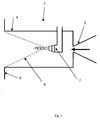
- Figure 1
- a combustor of a gas turbine engine with a fuel lance according to the invention,
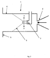
- Figure 2
- a fuel lance according to the state of the art,
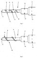
- Figure 3
- a fuel lance according to a first embodiment of the invention,
- Figure 4
- a fuel lance, which does not form part of the invention.
-
Figure 2 shows schematically a state of theart combustion chamber 1 of a gas turbine engine. The combustion chamber is an SEV combustor forming part of a gas turbine with sequential combustion, whereby fuel is combusted in a first combustor and the hot combustion gases are passed through a first turbine and subsequently supplied to a second combustor known as anSEV combustor 1 into which fuel is introduced. The hot combustion gases are introduced into theSEV combustor 1 through a vortex generator orgenerators 2. The combustion gases contain enough oxidation gases for further combustion in the SEV combustor. The SEVcombustor 1 comprises afuel lance 7 projecting into theSEV combustor 1 for introducing fuel into thecombustor 1. Fuel is injected radially (designated by arrow 3) from holes in the lance into the oxidization stream and interacts with the vortex/vortices created by thevortex generator 2. Particularly when using a hydrogen rich fuel such as MBTU the fuel reaches thewall 4 of the combustor far upstream of thecombustion front panel 5 as indicated by the dotted line 6 (in front of the dotted line represents a fuel air mixture whereas behind the dotted line represents the oxidization gas only). The presence of fuel near thewall 4 promotes auto ignition (i.e. premature ignition). -
Figure 1 shows schematically acombustor 1 of a gas turbine system. The combustion chamber may be anSEV combustor 1 forming part of a gas turbine with sequential combustion, whereby fuel is combusted in a first combustor and the hot combustion gases are passed through a first turbine and subsequently supplied to a second combustor known as anSEV combustor 1 into which fuel is introduced. The oxidization gases being introduced into theSEV combustor 1 through a vortex generator orgenerators 2. The fuel lance 7 according to the invention is provided for introducing fuel into the combustor. Thefuel lance 7 is designed to provide for better mixing of the fuel with the oxidization gas. Thefuel lance 7 of the invention is also formed so as to prevent the fuel from reaching thewall 4 of thecombustor 1 upstream of thecombustion front panel 5 therefore avoiding auto ignition. Thedotted line 6 once more representing the border between the upstream oxidization gas only area and the downstream fuel and oxidization gas mixture. -
Figure 3 shows one embodiment of afuel lance 7 according to the invention. The fuel lance hasfuel injector outlets 8. In order to achieve the desired distribution of fuel into the oxidization gas flow thefuel lance 7 is provided according to the invention with a helical orspiral formation 12. The helical orspiral formation 12 is arranged in a region of the lance where the fuel outlets 8 a situated. In the embodiment infigure 3 the helical formation is in the form of agroove 13 on theouter surface 9 of the fuel lance. At least onefuel outlet 8 is arranged in thegroove 13. Preferably a series offuel outlets 8 are arranged in thegroove 13 and spaced in the axial direction. Thefuel outlets 8 can also be arranged to be spaced in the circumferential directions. A series of smallerfuel injector outlets 8 provide a better fuel distributed than few larger fuel injector outlets. Thefuel injector outlets 8 which are arranged on the surface of thehelical groove 13 may be directed in a radial and/or axial directions. Thefuel injector outlets 8 arranged on the surface of thehelical groove 13 may also be directed in the direction of the groove i.e. they could have an axial, radial and circumferential/tangential component relative to the centre axis of thefuel lance 7. The helical formation improves the mixing of the fuel with the oxidization flow in the circumferential direction. This combined with the vortex flow of the oxidization gas from thevortex generator 2 leads to a superior mixing effect. The spread of the fuel is also controlled by the swirl imparted to the fuel thus improving flashback safety and reducing harmful emissions. - It should be understood that the
helical formation 12 must not extend fully around the lance, for example ahelical formation 12 extending sufficiently around theouter surface 9 of thelance 7 to impart a circumferential or tangential component to the fuel or the oxidization gas relative to thelance 7 may also be provided. -
Figure 4 shows an embodiment, which does not form part of the invention, of thehelical formation 12 which is provided by aprojection 10 on theouter surface 9 of thefuel lance 7. Similar features are provided with the same reference numerals as for the features infigure 3 . - The diameter of the lance must not remain constant. As shown in
figures 3 and 4 thefuel injector outlets 8 can be provided on the surface of thelance 7 at different radial distances from the centre axis. Fuel injected from afuel injector outlet 14 at an outer radius and upstream of the other fuel outlets reaches the main oxidization flow furthest from the centerline. Fuel injected however fromfuel injector outlets 15 at smaller radii and further downstream remains closer to the core of the flow. This staging effect also contributes to an improved mixing of the fuel with the oxidization flow. To achieve this effect the lance could have other forms than the stepped form shown infigure 3 . For example the lance could be generally cone shaped. The helical formation or formations could extend along the axial length of the cone. - The
lance 7 could also be a multifuel lance capable of injecting for example a combination of oil, natural gas, syngas or a hydrogen rich fuel such as MBTU. In this case thefuel lance 7 is provided with separate internal passages for each fuel type. Each fuel can be injected into the oxidization gas flow at positions described above with reference tofigure 3 . Advantageously the different fuels can be provided with fuel injector outlets at different positions on thefuel lance 7 corresponding to their particular fuel properties to achieve appropriate mixing with the oxidization gas flow. Advantageously the helical formation or groove 13 can be provided in the region where the natural gas or hydrogen rich fuel injector outlets are provided; the syngas is preferably introduced throughfuel outlets 16 in theouter surface 9 of the fuel lance 7 (i.e. not in the region of the helical formation), whereas oil is preferably introduced through anoutlet 11 of the lance tip. - A helical formation with an appropriate pitch for the combustor design should be chosen. The orientation of the helical formation can be chosen for optimal mixing for example the formation can either run in the clockwise or anticlockwise directions for example to either complement or contradict the direction of flow of the vortex flow of the oxidizations gases. Recirculation of the oxidization gas or fuel at the tip of the fuel lance can be prevented by providing a chamfered tip.
- The diameter and number of the fuel injector outlets in the groove can also be chosen for a particular combustor design. The injector outlets can be in the form of holes or slots.
- The cooling of the lance is provided by the fuel itself. The fuel supply passages are therefore suitable arranged to provide this effect.
- The
fuel lance 7 may be provided as a retrofitable fuel lance. In this waydifferent fuel lances 7 can be provided with different fuel injector outlet configurations for varying injector requirements. Thefuel lance 7 according to the invention enables the mixing of fuel and air has to be accomplished in the shortest possible residence time both which an important requirement of a retrofit lance. - The fuel lance described in preceding description may also be used in the combustor of a conventional gas turbine engine where compressed air is introduced into the combustor.
- The preceding description of the embodiments according to the present invention serves only an illustrative purpose and should not be considered to limit the scope of the invention.
Particularly, in view of the preferred embodiments, the man skilled in the art different changes and modifications in the form and details can be made without departing from the scope of the invention. Accordingly the disclosure of the current invention should not be limiting. The disclosure of the current invention should instead serve to clarify the scope of the invention which is set forth in the following claims. -
- 1.
- Combustor
- 2.
- Vortex generator(s)
- 3.
- Arrow
- 4.
- Combustor wall
- 5.
- Combustion front panel
- 6.
- Dotted line
- 7.
- Fuel lance
- 8.
- Fuel injector outlets
- 9.
- Outer surface
- 10.
- Projection
- 11.
- Fuel lance tip
- 12.
- Helical formation
- 13.
- Groove
- 14.
- Outlet
- 15.
- Fuel injector outlets
- 16.
- Fuel outlets
Claims (10)
- A fuel lance (7) for introducing fuel into a gas flow in a combustor 1 of a gas turbine engine, wherein a region of the lance through which the fuel is introduced into the gas flow comprises a generally helical formation (12), wherein the helical formation (12) comprises a helical groove (13) on the outer surface of the lance extending generally in the axial direction of the lance, characterised in that, a plurality of fuel outlets for introducing fuel into the gas flow are arranged on the surface of the helical groove (13) and are spaced apart in the axial and/or circumferential and/or radial directions.
- A fuel lance (7) according to claim 1, characterized in that the diameter of the fuel lance (7) in a region where fuel is introduced into the gas flow is not constant in the axial direction.
- A fuel lance (7) according to claim 1, characterized in that the lance (7) has multiple fuel passages for introducing different fuels into the gas flow.
- A fuel lance (7) according to claim 3, characterized in that a first fuel passage supplies a first fuel to a fuel outlet (8) in the surface of the grooves (13) and a second fuel passage supplies a second fuel to a fuel outlet (8) in the outer surface (9) of the lance.
- A fuel lance (7) according to any one of the preceding claims, characterized in that the lance is provided with a central passage for supplying oil to the tip (11) of the lance.
- A fuel lance (7) according to any one of the preceding claims, characterized in that the outlets (8) are formed by a hole or slot.
- A fuel lance (7) according to claim 1, characterized in that the fuel outlets (8) are arranged so that the fuel is introduced into the groove (13) in an axial or radial direction.
- A fuel lance (7) according to claim 1, characterized in that the fuel outlets (8) are arranged so that the fuel is introduced into the groove (13) in a tangential direction.
- A fuel lance (7) according to any one of the preceding claims, characterized in that a hydrogen rich fuel is introduced into the gas flow.
- A gas turbine engine having sequential combustion, whereby hot gas is produced in a first combustor and is subsequently introduced into a second combustor (1) in which a fuel lance (7) according to any one of the preceding claims is arranged for introducing fuel into the hot gas.
Applications Claiming Priority (1)
| Application Number | Priority Date | Filing Date | Title |
|---|---|---|---|
| US12/241,223 US8220271B2 (en) | 2008-09-30 | 2008-09-30 | Fuel lance for a gas turbine engine including outer helical grooves |
Publications (3)
| Publication Number | Publication Date |
|---|---|
| EP2169313A2 EP2169313A2 (en) | 2010-03-31 |
| EP2169313A3 EP2169313A3 (en) | 2014-12-24 |
| EP2169313B1 true EP2169313B1 (en) | 2016-06-29 |
Family
ID=41445538
Family Applications (1)
| Application Number | Title | Priority Date | Filing Date |
|---|---|---|---|
| EP09171054.1A Not-in-force EP2169313B1 (en) | 2008-09-30 | 2009-09-23 | Fuel Lance for a Gas Turbine Engine |
Country Status (3)
| Country | Link |
|---|---|
| US (1) | US8220271B2 (en) |
| EP (1) | EP2169313B1 (en) |
| JP (1) | JP5780697B2 (en) |
Families Citing this family (23)
| Publication number | Priority date | Publication date | Assignee | Title |
|---|---|---|---|---|
| GB2443429A (en) * | 2005-09-24 | 2008-05-07 | Siemens Ind Turbomachinery Ltd | Fuel Vaporisation Within a Burner Associated With a Combustion Chamber |
| EP2085695A1 (en) * | 2008-01-29 | 2009-08-05 | Siemens Aktiengesellschaft | Fuel nozzle with swirl duct and method for manufacturing a fuel nozzle |
| EP2107301B1 (en) * | 2008-04-01 | 2016-01-06 | Siemens Aktiengesellschaft | Gas injection in a burner |
| US8511059B2 (en) * | 2008-09-30 | 2013-08-20 | Alstom Technology Ltd. | Methods of reducing emissions for a sequential combustion gas turbine and combustor for a gas turbine |
| US8220269B2 (en) * | 2008-09-30 | 2012-07-17 | Alstom Technology Ltd. | Combustor for a gas turbine engine with effusion cooled baffle |
| EP2348256A1 (en) * | 2010-01-26 | 2011-07-27 | Alstom Technology Ltd | Method for operating a gas turbine and gas turbine |
| US9383097B2 (en) | 2011-03-10 | 2016-07-05 | Rolls-Royce Plc | Systems and method for cooling a staged airblast fuel injector |
| US9310073B2 (en) | 2011-03-10 | 2016-04-12 | Rolls-Royce Plc | Liquid swirler flow control |
| MX355007B (en) | 2012-02-27 | 2018-03-28 | Deec Inc | Oxygen-rich plasma generators for boosting internal combustion engines. |
| EP2667098B1 (en) * | 2012-05-25 | 2017-04-12 | Rolls-Royce plc | A liquid fuel injector |
| US9217373B2 (en) * | 2013-02-27 | 2015-12-22 | General Electric Company | Fuel nozzle for reducing modal coupling of combustion dynamics |
| EP2789915A1 (en) * | 2013-04-10 | 2014-10-15 | Alstom Technology Ltd | Method for operating a combustion chamber and combustion chamber |
| WO2015147932A2 (en) | 2013-12-19 | 2015-10-01 | United Technologies Corporation | Dilution passage arrangement for gas turbine engine combustor |
| EP3224544A1 (en) * | 2014-11-26 | 2017-10-04 | Siemens Aktiengesellschaft | Fuel lance with means for interacting with a flow of air and improve breakage of an ejected liquid jet of fuel |
| US10094569B2 (en) | 2014-12-11 | 2018-10-09 | General Electric Company | Injecting apparatus with reheat combustor and turbomachine |
| US10094570B2 (en) | 2014-12-11 | 2018-10-09 | General Electric Company | Injector apparatus and reheat combustor |
| US10107498B2 (en) | 2014-12-11 | 2018-10-23 | General Electric Company | Injection systems for fuel and gas |
| US10094571B2 (en) | 2014-12-11 | 2018-10-09 | General Electric Company | Injector apparatus with reheat combustor and turbomachine |
| AU2017229114B2 (en) * | 2016-03-07 | 2023-01-12 | HyTech Power, Inc. | A method of generating and distributing a second fuel for an internal combustion engine |
| US10739003B2 (en) | 2016-10-03 | 2020-08-11 | United Technologies Corporation | Radial fuel shifting and biasing in an axial staged combustor for a gas turbine engine |
| US10508811B2 (en) | 2016-10-03 | 2019-12-17 | United Technologies Corporation | Circumferential fuel shifting and biasing in an axial staged combustor for a gas turbine engine |
| US20190234348A1 (en) | 2018-01-29 | 2019-08-01 | Hytech Power, Llc | Ultra Low HHO Injection |
| CN115917215A (en) * | 2020-07-17 | 2023-04-04 | 西门子能源全球有限两合公司 | Premixing injector assembly in a gas turbine engine |
Family Cites Families (73)
| Publication number | Priority date | Publication date | Assignee | Title |
|---|---|---|---|---|
| US1866311A (en) * | 1931-03-26 | 1932-07-05 | Leiman Bros Inc | Hydrocarbon burner |
| US2701164A (en) * | 1951-04-26 | 1955-02-01 | Gen Motors Corp | Duplex fuel nozzle |
| US3510064A (en) * | 1966-10-26 | 1970-05-05 | British Oxygen Co Ltd | Oxy-fuel flame burner nozzles |
| US3648457A (en) | 1970-04-30 | 1972-03-14 | Gen Electric | Combustion apparatus |
| CA1060774A (en) * | 1975-08-27 | 1979-08-21 | Esso Societe Anonyme Francaise | Atomizer and uses thereof |
| US4258544A (en) * | 1978-09-15 | 1981-03-31 | Caterpillar Tractor Co. | Dual fluid fuel nozzle |
| US4457241A (en) * | 1981-12-23 | 1984-07-03 | Riley Stoker Corporation | Method of burning pulverized coal |
| JPS6057131A (en) | 1983-09-08 | 1985-04-02 | Hitachi Ltd | Fuel feeding process for gas turbine combustor |
| US4982570A (en) | 1986-11-25 | 1991-01-08 | General Electric Company | Premixed pilot nozzle for dry low Nox combustor |
| US4952136A (en) * | 1987-05-12 | 1990-08-28 | Control Systems Company | Burner assembly for oil fired furnaces |
| JPH0684817B2 (en) | 1988-08-08 | 1994-10-26 | 株式会社日立製作所 | Gas turbine combustor and operating method thereof |
| JPH0772616B2 (en) | 1989-05-24 | 1995-08-02 | 株式会社日立製作所 | Combustor and operating method thereof |
| US5749219A (en) | 1989-11-30 | 1998-05-12 | United Technologies Corporation | Combustor with first and second zones |
| US5129333A (en) * | 1991-06-24 | 1992-07-14 | Aga Ab | Apparatus and method for recycling waste |
| US5406799A (en) | 1992-06-12 | 1995-04-18 | United Technologies Corporation | Combustion chamber |
| US5405082A (en) * | 1993-07-06 | 1995-04-11 | Corning Incorporated | Oxy/fuel burner with low volume fuel stream projection |
| US5393220A (en) * | 1993-12-06 | 1995-02-28 | Praxair Technology, Inc. | Combustion apparatus and process |
| US5465570A (en) | 1993-12-22 | 1995-11-14 | United Technologies Corporation | Fuel control system for a staged combustor |
| CH688899A5 (en) * | 1994-05-26 | 1998-05-15 | Asea Brown Boveri | A method for controlling a gas turbine group. |
| DE4424639A1 (en) * | 1994-07-13 | 1996-01-18 | Abb Research Ltd | Method and device for fuel distribution in a burner suitable for both liquid and gaseous fuels |
| US5701732A (en) * | 1995-01-24 | 1997-12-30 | Delavan Inc. | Method and apparatus for purging of gas turbine injectors |
| US5836164A (en) | 1995-01-30 | 1998-11-17 | Hitachi, Ltd. | Gas turbine combustor |
| US5687571A (en) | 1995-02-20 | 1997-11-18 | Asea Brown Boveri Ag | Combustion chamber with two-stage combustion |
| US6076356A (en) * | 1996-03-13 | 2000-06-20 | Parker-Hannifin Corporation | Internally heatshielded nozzle |
| DE19737997A1 (en) | 1997-08-30 | 1999-03-04 | Asea Brown Boveri | plenum |
| ATE234444T1 (en) | 1997-10-27 | 2003-03-15 | Alstom Switzerland Ltd | METHOD FOR OPERATING A PREMIX BURNER |
| EP0916894B1 (en) | 1997-11-13 | 2003-09-24 | ALSTOM (Switzerland) Ltd | Burner for operating a heat generator |
| DE59710734D1 (en) * | 1997-12-08 | 2003-10-16 | Alstom Switzerland Ltd | Process for regulating a gas turbine group |
| US6029910A (en) * | 1998-02-05 | 2000-02-29 | American Air Liquide, Inc. | Low firing rate oxy-fuel burner |
| US6101816A (en) * | 1998-04-28 | 2000-08-15 | Advanced Technology Materials, Inc. | Fluid storage and dispensing system |
| US6098407A (en) * | 1998-06-08 | 2000-08-08 | United Technologies Corporation | Premixing fuel injector with improved secondary fuel-air injection |
| US6339923B1 (en) | 1998-10-09 | 2002-01-22 | General Electric Company | Fuel air mixer for a radial dome in a gas turbine engine combustor |
| US6089024A (en) | 1998-11-25 | 2000-07-18 | Elson Corporation | Steam-augmented gas turbine |
| US6460344B1 (en) | 1999-05-07 | 2002-10-08 | Parker-Hannifin Corporation | Fuel atomization method for turbine combustion engines having aerodynamic turning vanes |
| US6174161B1 (en) * | 1999-07-30 | 2001-01-16 | Air Products And Chemical, Inc. | Method and apparatus for partial oxidation of black liquor, liquid fuels and slurries |
| US6089468A (en) * | 1999-11-08 | 2000-07-18 | Husky Injection Molding Systems Ltd. | Nozzle tip with weld line eliminator |
| US7224840B2 (en) * | 2000-10-26 | 2007-05-29 | International Business Machines Corporation | Method, system, and program for error recovery while decoding compressed data |
| DE10061526A1 (en) | 2000-12-11 | 2002-06-20 | Alstom Switzerland Ltd | Premix burner arrangement for operating a combustion chamber |
| US6622488B2 (en) * | 2001-03-21 | 2003-09-23 | Parker-Hannifin Corporation | Pure airblast nozzle |
| US6539724B2 (en) * | 2001-03-30 | 2003-04-01 | Delavan Inc | Airblast fuel atomization system |
| US6581386B2 (en) | 2001-09-29 | 2003-06-24 | General Electric Company | Threaded combustor baffle |
| WO2003038242A1 (en) * | 2001-10-30 | 2003-05-08 | Alstom Technology Ltd | Turbine unit |
| US6832482B2 (en) | 2002-06-25 | 2004-12-21 | Power Systems Mfg, Llc | Pressure ram device on a gas turbine combustor |
| EP1389713A1 (en) | 2002-08-12 | 2004-02-18 | ALSTOM (Switzerland) Ltd | Premixed exit ring pilot burner |
| JP3940705B2 (en) | 2003-06-19 | 2007-07-04 | 株式会社日立製作所 | Gas turbine combustor and fuel supply method thereof |
| KR100520932B1 (en) * | 2003-11-24 | 2005-10-17 | 삼성전자주식회사 | Toner-layer blade and developing unit having the same for image forming apparatus |
| JP2005180799A (en) * | 2003-12-19 | 2005-07-07 | Mitsubishi Heavy Ind Ltd | Premixing fuel nozzle, combustor, and gas turbine using it |
| DE10360951A1 (en) * | 2003-12-23 | 2005-07-28 | Alstom Technology Ltd | Thermal power plant with sequential combustion and reduced CO2 emissions and method of operating such a plant |
| US7174717B2 (en) * | 2003-12-24 | 2007-02-13 | Pratt & Whitney Canada Corp. | Helical channel fuel distributor and method |
| US7082770B2 (en) | 2003-12-24 | 2006-08-01 | Martling Vincent C | Flow sleeve for a low NOx combustor |
| US7185497B2 (en) | 2004-05-04 | 2007-03-06 | Honeywell International, Inc. | Rich quick mix combustion system |
| WO2005124231A2 (en) | 2004-06-11 | 2005-12-29 | Vast Power Systems, Inc. | Low emissions combustion apparatus and method |
| US7883026B2 (en) * | 2004-06-30 | 2011-02-08 | Illinois Tool Works Inc. | Fluid atomizing system and method |
| FR2875584B1 (en) * | 2004-09-23 | 2009-10-30 | Snecma Moteurs Sa | EFFERVESCENCE INJECTOR FOR AEROMECHANICAL AIR / FUEL INJECTION SYSTEM IN A TURBOMACHINE COMBUSTION CHAMBER |
| ES2279501T3 (en) * | 2004-09-23 | 2007-08-16 | Innova Patent Gmbh | DEVICE FOR THE HOLDING OF A MEANS OF TRANSPORTATION OF A FUNCTIONAL INSTALLATION IN A SUSPENSION BAR. |
| US7416404B2 (en) * | 2005-04-18 | 2008-08-26 | General Electric Company | Feed injector for gasification and related method |
| DE102005042889B4 (en) * | 2005-09-09 | 2019-05-09 | Ansaldo Energia Switzerland AG | Gas turbine group |
| US20070107437A1 (en) | 2005-11-15 | 2007-05-17 | Evulet Andrei T | Low emission combustion and method of operation |
| EP1840354B1 (en) | 2006-03-28 | 2017-11-29 | Ansaldo Energia IP UK Limited | Method for operating a gas turbine plant and gas turbine plant for carrying out the method |
| EP2002185B8 (en) * | 2006-03-31 | 2016-09-14 | General Electric Technology GmbH | Fuel lance for a gas turbine plant and a method of operating a fuel lance |
| US7762070B2 (en) * | 2006-05-11 | 2010-07-27 | Siemens Energy, Inc. | Pilot nozzle heat shield having internal turbulators |
| EP2024620B1 (en) * | 2006-06-07 | 2015-07-29 | Alstom Technology Ltd | Method of operating a gas turbine and combined cycle power plant for carrying out the method |
| US7908864B2 (en) * | 2006-10-06 | 2011-03-22 | General Electric Company | Combustor nozzle for a fuel-flexible combustion system |
| EP1914407B1 (en) * | 2006-10-16 | 2012-01-04 | Alstom Technology Ltd | Method for operating a gas turbine plant |
| US8015815B2 (en) * | 2007-04-18 | 2011-09-13 | Parker-Hannifin Corporation | Fuel injector nozzles, with labyrinth grooves, for gas turbine engines |
| US8020384B2 (en) * | 2007-06-14 | 2011-09-20 | Parker-Hannifin Corporation | Fuel injector nozzle with macrolaminate fuel swirler |
| EP2085695A1 (en) * | 2008-01-29 | 2009-08-05 | Siemens Aktiengesellschaft | Fuel nozzle with swirl duct and method for manufacturing a fuel nozzle |
| EP2090830B1 (en) | 2008-02-13 | 2017-01-18 | General Electric Technology GmbH | Fuel supply arrangement |
| US8281595B2 (en) * | 2008-05-28 | 2012-10-09 | General Electric Company | Fuse for flame holding abatement in premixer of combustion chamber of gas turbine and associated method |
| US8272218B2 (en) * | 2008-09-24 | 2012-09-25 | Siemens Energy, Inc. | Spiral cooled fuel nozzle |
| US8511059B2 (en) | 2008-09-30 | 2013-08-20 | Alstom Technology Ltd. | Methods of reducing emissions for a sequential combustion gas turbine and combustor for a gas turbine |
| US8220269B2 (en) | 2008-09-30 | 2012-07-17 | Alstom Technology Ltd. | Combustor for a gas turbine engine with effusion cooled baffle |
| US20100205970A1 (en) * | 2009-02-19 | 2010-08-19 | General Electric Company | Systems, Methods, and Apparatus Providing a Secondary Fuel Nozzle Assembly |
-
2008
- 2008-09-30 US US12/241,223 patent/US8220271B2/en not_active Expired - Fee Related
-
2009
- 2009-09-23 EP EP09171054.1A patent/EP2169313B1/en not_active Not-in-force
- 2009-09-29 JP JP2009224157A patent/JP5780697B2/en not_active Expired - Fee Related
Also Published As
| Publication number | Publication date |
|---|---|
| JP5780697B2 (en) | 2015-09-16 |
| EP2169313A2 (en) | 2010-03-31 |
| US20100077756A1 (en) | 2010-04-01 |
| JP2010085087A (en) | 2010-04-15 |
| US8220271B2 (en) | 2012-07-17 |
| EP2169313A3 (en) | 2014-12-24 |
Similar Documents
| Publication | Publication Date | Title |
|---|---|---|
| EP2169313B1 (en) | Fuel Lance for a Gas Turbine Engine | |
| EP2522911B1 (en) | Burner with a lobed swirler | |
| EP2496884B1 (en) | Reheat burner injection system | |
| JP5411468B2 (en) | Turbine engine fuel delivery system and system | |
| EP2496880B1 (en) | Reheat burner injection system | |
| EP2522912B1 (en) | Flow straightener and mixer | |
| JP5638613B2 (en) | Inlet premixer for combustion equipment | |
| JP5850900B2 (en) | Reheat burner arrangement | |
| US8387393B2 (en) | Flashback resistant fuel injection system | |
| JP2010085087A5 (en) | ||
| US8893500B2 (en) | Lean direct fuel injector | |
| EP2400216A1 (en) | Lance of a reheat burner | |
| JP2012241982A (en) | Combustor | |
| US8919132B2 (en) | Method of operating a gas turbine engine | |
| RU2686652C2 (en) | Method for operation of combustion device for gas turbine and combustion device for gas turbine | |
| CN1571905A (en) | Burner for synthesis gas | |
| EP1835231A1 (en) | Burner in particular for a gas turbine combustor, and method of operating a burner | |
| US9182124B2 (en) | Gas turbine and fuel injector for the same | |
| EP3472518B1 (en) | Fuel oil axial stage combustion for improved turbine combustor performance | |
| US20110056205A1 (en) | Burner arrangement and use of same | |
| JP2011075173A (en) | Combustor | |
| EP2933559A1 (en) | Fuel mixing arragement and combustor with such a fuel mixing arrangement | |
| EP3821174B1 (en) | Gas turbine burner with pilot fuel-air mixing | |
| EP1994334B1 (en) | Combustor and method of operating a combustor | |
| CN117916526A (en) | Burner and method for its manufacture |
Legal Events
| Date | Code | Title | Description |
|---|---|---|---|
| PUAI | Public reference made under article 153(3) epc to a published international application that has entered the european phase |
Free format text: ORIGINAL CODE: 0009012 |
|
| AK | Designated contracting states |
Kind code of ref document: A2 Designated state(s): AT BE BG CH CY CZ DE DK EE ES FI FR GB GR HR HU IE IS IT LI LT LU LV MC MK MT NL NO PL PT RO SE SI SK SM TR |
|
| PUAL | Search report despatched |
Free format text: ORIGINAL CODE: 0009013 |
|
| AK | Designated contracting states |
Kind code of ref document: A3 Designated state(s): AT BE BG CH CY CZ DE DK EE ES FI FR GB GR HR HU IE IS IT LI LT LU LV MC MK MT NL NO PL PT RO SE SI SK SM TR |
|
| RIC1 | Information provided on ipc code assigned before grant |
Ipc: F23R 3/28 20060101AFI20141118BHEP |
|
| 17P | Request for examination filed |
Effective date: 20150624 |
|
| RBV | Designated contracting states (corrected) |
Designated state(s): AT BE BG CH CY CZ DE DK EE ES FI FR GB GR HR HU IE IS IT LI LT LU LV MC MK MT NL NO PL PT RO SE SI SK SM TR |
|
| GRAP | Despatch of communication of intention to grant a patent |
Free format text: ORIGINAL CODE: EPIDOSNIGR1 |
|
| INTG | Intention to grant announced |
Effective date: 20160104 |
|
| GRAS | Grant fee paid |
Free format text: ORIGINAL CODE: EPIDOSNIGR3 |
|
| GRAA | (expected) grant |
Free format text: ORIGINAL CODE: 0009210 |
|
| AK | Designated contracting states |
Kind code of ref document: B1 Designated state(s): AT BE BG CH CY CZ DE DK EE ES FI FR GB GR HR HU IE IS IT LI LT LU LV MC MK MT NL NO PL PT RO SE SI SK SM TR |
|
| REG | Reference to a national code |
Ref country code: GB Ref legal event code: FG4D |
|
| REG | Reference to a national code |
Ref country code: CH Ref legal event code: EP |
|
| REG | Reference to a national code |
Ref country code: AT Ref legal event code: REF Ref document number: 809420 Country of ref document: AT Kind code of ref document: T Effective date: 20160715 |
|
| REG | Reference to a national code |
Ref country code: IE Ref legal event code: FG4D |
|
| REG | Reference to a national code |
Ref country code: DE Ref legal event code: R096 Ref document number: 602009039423 Country of ref document: DE |
|
| RAP2 | Party data changed (patent owner data changed or rights of a patent transferred) |
Owner name: GENERAL ELECTRIC TECHNOLOGY GMBH |
|
| REG | Reference to a national code |
Ref country code: LT Ref legal event code: MG4D |
|
| PG25 | Lapsed in a contracting state [announced via postgrant information from national office to epo] |
Ref country code: LT Free format text: LAPSE BECAUSE OF FAILURE TO SUBMIT A TRANSLATION OF THE DESCRIPTION OR TO PAY THE FEE WITHIN THE PRESCRIBED TIME-LIMIT Effective date: 20160629 Ref country code: NO Free format text: LAPSE BECAUSE OF FAILURE TO SUBMIT A TRANSLATION OF THE DESCRIPTION OR TO PAY THE FEE WITHIN THE PRESCRIBED TIME-LIMIT Effective date: 20160929 Ref country code: FI Free format text: LAPSE BECAUSE OF FAILURE TO SUBMIT A TRANSLATION OF THE DESCRIPTION OR TO PAY THE FEE WITHIN THE PRESCRIBED TIME-LIMIT Effective date: 20160629 |
|
| REG | Reference to a national code |
Ref country code: NL Ref legal event code: MP Effective date: 20160629 |
|
| PG25 | Lapsed in a contracting state [announced via postgrant information from national office to epo] |
Ref country code: SE Free format text: LAPSE BECAUSE OF FAILURE TO SUBMIT A TRANSLATION OF THE DESCRIPTION OR TO PAY THE FEE WITHIN THE PRESCRIBED TIME-LIMIT Effective date: 20160629 Ref country code: NL Free format text: LAPSE BECAUSE OF FAILURE TO SUBMIT A TRANSLATION OF THE DESCRIPTION OR TO PAY THE FEE WITHIN THE PRESCRIBED TIME-LIMIT Effective date: 20160629 Ref country code: LV Free format text: LAPSE BECAUSE OF FAILURE TO SUBMIT A TRANSLATION OF THE DESCRIPTION OR TO PAY THE FEE WITHIN THE PRESCRIBED TIME-LIMIT Effective date: 20160629 Ref country code: HR Free format text: LAPSE BECAUSE OF FAILURE TO SUBMIT A TRANSLATION OF THE DESCRIPTION OR TO PAY THE FEE WITHIN THE PRESCRIBED TIME-LIMIT Effective date: 20160629 Ref country code: GR Free format text: LAPSE BECAUSE OF FAILURE TO SUBMIT A TRANSLATION OF THE DESCRIPTION OR TO PAY THE FEE WITHIN THE PRESCRIBED TIME-LIMIT Effective date: 20160930 |
|
| REG | Reference to a national code |
Ref country code: AT Ref legal event code: MK05 Ref document number: 809420 Country of ref document: AT Kind code of ref document: T Effective date: 20160629 |
|
| PG25 | Lapsed in a contracting state [announced via postgrant information from national office to epo] |
Ref country code: IS Free format text: LAPSE BECAUSE OF FAILURE TO SUBMIT A TRANSLATION OF THE DESCRIPTION OR TO PAY THE FEE WITHIN THE PRESCRIBED TIME-LIMIT Effective date: 20161029 Ref country code: CZ Free format text: LAPSE BECAUSE OF FAILURE TO SUBMIT A TRANSLATION OF THE DESCRIPTION OR TO PAY THE FEE WITHIN THE PRESCRIBED TIME-LIMIT Effective date: 20160629 Ref country code: RO Free format text: LAPSE BECAUSE OF FAILURE TO SUBMIT A TRANSLATION OF THE DESCRIPTION OR TO PAY THE FEE WITHIN THE PRESCRIBED TIME-LIMIT Effective date: 20160629 Ref country code: EE Free format text: LAPSE BECAUSE OF FAILURE TO SUBMIT A TRANSLATION OF THE DESCRIPTION OR TO PAY THE FEE WITHIN THE PRESCRIBED TIME-LIMIT Effective date: 20160629 Ref country code: IT Free format text: LAPSE BECAUSE OF FAILURE TO SUBMIT A TRANSLATION OF THE DESCRIPTION OR TO PAY THE FEE WITHIN THE PRESCRIBED TIME-LIMIT Effective date: 20160629 Ref country code: SK Free format text: LAPSE BECAUSE OF FAILURE TO SUBMIT A TRANSLATION OF THE DESCRIPTION OR TO PAY THE FEE WITHIN THE PRESCRIBED TIME-LIMIT Effective date: 20160629 |
|
| PG25 | Lapsed in a contracting state [announced via postgrant information from national office to epo] |
Ref country code: SM Free format text: LAPSE BECAUSE OF FAILURE TO SUBMIT A TRANSLATION OF THE DESCRIPTION OR TO PAY THE FEE WITHIN THE PRESCRIBED TIME-LIMIT Effective date: 20160629 Ref country code: PL Free format text: LAPSE BECAUSE OF FAILURE TO SUBMIT A TRANSLATION OF THE DESCRIPTION OR TO PAY THE FEE WITHIN THE PRESCRIBED TIME-LIMIT Effective date: 20160629 Ref country code: ES Free format text: LAPSE BECAUSE OF FAILURE TO SUBMIT A TRANSLATION OF THE DESCRIPTION OR TO PAY THE FEE WITHIN THE PRESCRIBED TIME-LIMIT Effective date: 20160629 Ref country code: PT Free format text: LAPSE BECAUSE OF FAILURE TO SUBMIT A TRANSLATION OF THE DESCRIPTION OR TO PAY THE FEE WITHIN THE PRESCRIBED TIME-LIMIT Effective date: 20161031 Ref country code: BE Free format text: LAPSE BECAUSE OF NON-PAYMENT OF DUE FEES Effective date: 20160629 Ref country code: AT Free format text: LAPSE BECAUSE OF FAILURE TO SUBMIT A TRANSLATION OF THE DESCRIPTION OR TO PAY THE FEE WITHIN THE PRESCRIBED TIME-LIMIT Effective date: 20160629 |
|
| REG | Reference to a national code |
Ref country code: DE Ref legal event code: R097 Ref document number: 602009039423 Country of ref document: DE |
|
| REG | Reference to a national code |
Ref country code: DE Ref legal event code: R119 Ref document number: 602009039423 Country of ref document: DE |
|
| PG25 | Lapsed in a contracting state [announced via postgrant information from national office to epo] |
Ref country code: MC Free format text: LAPSE BECAUSE OF FAILURE TO SUBMIT A TRANSLATION OF THE DESCRIPTION OR TO PAY THE FEE WITHIN THE PRESCRIBED TIME-LIMIT Effective date: 20160629 |
|
| REG | Reference to a national code |
Ref country code: CH Ref legal event code: PL |
|
| PLBE | No opposition filed within time limit |
Free format text: ORIGINAL CODE: 0009261 |
|
| STAA | Information on the status of an ep patent application or granted ep patent |
Free format text: STATUS: NO OPPOSITION FILED WITHIN TIME LIMIT |
|
| GBPC | Gb: european patent ceased through non-payment of renewal fee |
Effective date: 20160929 |
|
| PG25 | Lapsed in a contracting state [announced via postgrant information from national office to epo] |
Ref country code: DK Free format text: LAPSE BECAUSE OF FAILURE TO SUBMIT A TRANSLATION OF THE DESCRIPTION OR TO PAY THE FEE WITHIN THE PRESCRIBED TIME-LIMIT Effective date: 20160629 |
|
| 26N | No opposition filed |
Effective date: 20170330 |
|
| STAA | Information on the status of an ep patent application or granted ep patent |
Free format text: STATUS: NO OPPOSITION FILED WITHIN TIME LIMIT |
|
| REG | Reference to a national code |
Ref country code: IE Ref legal event code: MM4A |
|
| REG | Reference to a national code |
Ref country code: FR Ref legal event code: ST Effective date: 20170531 |
|
| PG25 | Lapsed in a contracting state [announced via postgrant information from national office to epo] |
Ref country code: DE Free format text: LAPSE BECAUSE OF NON-PAYMENT OF DUE FEES Effective date: 20170401 Ref country code: FR Free format text: LAPSE BECAUSE OF NON-PAYMENT OF DUE FEES Effective date: 20160930 Ref country code: GB Free format text: LAPSE BECAUSE OF NON-PAYMENT OF DUE FEES Effective date: 20160929 Ref country code: CH Free format text: LAPSE BECAUSE OF NON-PAYMENT OF DUE FEES Effective date: 20160930 Ref country code: IE Free format text: LAPSE BECAUSE OF NON-PAYMENT OF DUE FEES Effective date: 20160923 Ref country code: LI Free format text: LAPSE BECAUSE OF NON-PAYMENT OF DUE FEES Effective date: 20160930 |
|
| PG25 | Lapsed in a contracting state [announced via postgrant information from national office to epo] |
Ref country code: SI Free format text: LAPSE BECAUSE OF FAILURE TO SUBMIT A TRANSLATION OF THE DESCRIPTION OR TO PAY THE FEE WITHIN THE PRESCRIBED TIME-LIMIT Effective date: 20160629 Ref country code: LU Free format text: LAPSE BECAUSE OF NON-PAYMENT OF DUE FEES Effective date: 20160923 Ref country code: BG Free format text: LAPSE BECAUSE OF FAILURE TO SUBMIT A TRANSLATION OF THE DESCRIPTION OR TO PAY THE FEE WITHIN THE PRESCRIBED TIME-LIMIT Effective date: 20160929 |
|
| PG25 | Lapsed in a contracting state [announced via postgrant information from national office to epo] |
Ref country code: CY Free format text: LAPSE BECAUSE OF FAILURE TO SUBMIT A TRANSLATION OF THE DESCRIPTION OR TO PAY THE FEE WITHIN THE PRESCRIBED TIME-LIMIT Effective date: 20160629 Ref country code: HU Free format text: LAPSE BECAUSE OF FAILURE TO SUBMIT A TRANSLATION OF THE DESCRIPTION OR TO PAY THE FEE WITHIN THE PRESCRIBED TIME-LIMIT; INVALID AB INITIO Effective date: 20090923 |
|
| PG25 | Lapsed in a contracting state [announced via postgrant information from national office to epo] |
Ref country code: MT Free format text: LAPSE BECAUSE OF NON-PAYMENT OF DUE FEES Effective date: 20160930 Ref country code: TR Free format text: LAPSE BECAUSE OF FAILURE TO SUBMIT A TRANSLATION OF THE DESCRIPTION OR TO PAY THE FEE WITHIN THE PRESCRIBED TIME-LIMIT Effective date: 20160629 Ref country code: MK Free format text: LAPSE BECAUSE OF FAILURE TO SUBMIT A TRANSLATION OF THE DESCRIPTION OR TO PAY THE FEE WITHIN THE PRESCRIBED TIME-LIMIT Effective date: 20160629 |