EP2522912B1 - Flow straightener and mixer - Google Patents
Flow straightener and mixer Download PDFInfo
- Publication number
- EP2522912B1 EP2522912B1 EP12167781.9A EP12167781A EP2522912B1 EP 2522912 B1 EP2522912 B1 EP 2522912B1 EP 12167781 A EP12167781 A EP 12167781A EP 2522912 B1 EP2522912 B1 EP 2522912B1
- Authority
- EP
- European Patent Office
- Prior art keywords
- fuel
- burner
- streamlined
- flow
- lobes
- Prior art date
- Legal status (The legal status is an assumption and is not a legal conclusion. Google has not performed a legal analysis and makes no representation as to the accuracy of the status listed.)
- Active
Links
- 239000000446 fuel Substances 0.000 claims description 168
- 238000002156 mixing Methods 0.000 claims description 101
- 238000002347 injection Methods 0.000 claims description 62
- 239000007924 injection Substances 0.000 claims description 62
- 238000002485 combustion reaction Methods 0.000 claims description 60
- 239000007789 gas Substances 0.000 claims description 43
- 238000001816 cooling Methods 0.000 claims description 12
- 239000007788 liquid Substances 0.000 claims description 12
- 230000009257 reactivity Effects 0.000 claims description 10
- 238000011144 upstream manufacturing Methods 0.000 claims description 10
- 239000012159 carrier gas Substances 0.000 claims description 7
- 238000000034 method Methods 0.000 claims description 6
- 230000007704 transition Effects 0.000 claims description 5
- UFHFLCQGNIYNRP-UHFFFAOYSA-N Hydrogen Chemical compound [H][H] UFHFLCQGNIYNRP-UHFFFAOYSA-N 0.000 claims description 4
- 238000006073 displacement reaction Methods 0.000 claims description 4
- 239000001257 hydrogen Substances 0.000 claims description 3
- 229910052739 hydrogen Inorganic materials 0.000 claims description 3
- 230000009467 reduction Effects 0.000 claims description 3
- 239000002826 coolant Substances 0.000 claims description 2
- 239000000203 mixture Substances 0.000 description 21
- 238000013461 design Methods 0.000 description 12
- 230000003750 conditioning effect Effects 0.000 description 8
- VNWKTOKETHGBQD-UHFFFAOYSA-N methane Chemical compound C VNWKTOKETHGBQD-UHFFFAOYSA-N 0.000 description 8
- 230000001590 oxidative effect Effects 0.000 description 6
- 206010016754 Flashback Diseases 0.000 description 5
- 230000008901 benefit Effects 0.000 description 5
- 239000002737 fuel gas Substances 0.000 description 4
- 239000003345 natural gas Substances 0.000 description 4
- 239000007800 oxidant agent Substances 0.000 description 4
- 230000008859 change Effects 0.000 description 3
- 230000004907 flux Effects 0.000 description 3
- 230000035515 penetration Effects 0.000 description 3
- 238000010791 quenching Methods 0.000 description 3
- 238000000926 separation method Methods 0.000 description 3
- IJGRMHOSHXDMSA-UHFFFAOYSA-N Atomic nitrogen Chemical compound N#N IJGRMHOSHXDMSA-UHFFFAOYSA-N 0.000 description 2
- 230000007613 environmental effect Effects 0.000 description 2
- 239000012530 fluid Substances 0.000 description 2
- 239000008240 homogeneous mixture Substances 0.000 description 2
- 230000003993 interaction Effects 0.000 description 2
- 230000010349 pulsation Effects 0.000 description 2
- 230000004913 activation Effects 0.000 description 1
- 238000013459 approach Methods 0.000 description 1
- 230000009286 beneficial effect Effects 0.000 description 1
- 230000003197 catalytic effect Effects 0.000 description 1
- 239000000567 combustion gas Substances 0.000 description 1
- 230000001143 conditioned effect Effects 0.000 description 1
- 230000009849 deactivation Effects 0.000 description 1
- 230000001419 dependent effect Effects 0.000 description 1
- 238000007865 diluting Methods 0.000 description 1
- 230000000694 effects Effects 0.000 description 1
- 230000008030 elimination Effects 0.000 description 1
- 238000003379 elimination reaction Methods 0.000 description 1
- 238000004401 flow injection analysis Methods 0.000 description 1
- 230000000116 mitigating effect Effects 0.000 description 1
- 238000012986 modification Methods 0.000 description 1
- 230000004048 modification Effects 0.000 description 1
- 229910052757 nitrogen Inorganic materials 0.000 description 1
- 238000011017 operating method Methods 0.000 description 1
- 238000005457 optimization Methods 0.000 description 1
- 230000003647 oxidation Effects 0.000 description 1
- 238000007254 oxidation reaction Methods 0.000 description 1
- 230000000737 periodic effect Effects 0.000 description 1
- 230000008569 process Effects 0.000 description 1
- 238000010008 shearing Methods 0.000 description 1
- 230000002269 spontaneous effect Effects 0.000 description 1
- 230000003068 static effect Effects 0.000 description 1
- 238000012546 transfer Methods 0.000 description 1
Images


Classifications
-
- F—MECHANICAL ENGINEERING; LIGHTING; HEATING; WEAPONS; BLASTING
- F23—COMBUSTION APPARATUS; COMBUSTION PROCESSES
- F23R—GENERATING COMBUSTION PRODUCTS OF HIGH PRESSURE OR HIGH VELOCITY, e.g. GAS-TURBINE COMBUSTION CHAMBERS
- F23R3/00—Continuous combustion chambers using liquid or gaseous fuel
- F23R3/28—Continuous combustion chambers using liquid or gaseous fuel characterised by the fuel supply
- F23R3/34—Feeding into different combustion zones
-
- B—PERFORMING OPERATIONS; TRANSPORTING
- B01—PHYSICAL OR CHEMICAL PROCESSES OR APPARATUS IN GENERAL
- B01F—MIXING, e.g. DISSOLVING, EMULSIFYING OR DISPERSING
- B01F25/00—Flow mixers; Mixers for falling materials, e.g. solid particles
- B01F25/30—Injector mixers
- B01F25/31—Injector mixers in conduits or tubes through which the main component flows
- B01F25/313—Injector mixers in conduits or tubes through which the main component flows wherein additional components are introduced in the centre of the conduit
- B01F25/3131—Injector mixers in conduits or tubes through which the main component flows wherein additional components are introduced in the centre of the conduit with additional mixing means other than injector mixers, e.g. screens, baffles or rotating elements
-
- B—PERFORMING OPERATIONS; TRANSPORTING
- B01—PHYSICAL OR CHEMICAL PROCESSES OR APPARATUS IN GENERAL
- B01F—MIXING, e.g. DISSOLVING, EMULSIFYING OR DISPERSING
- B01F25/00—Flow mixers; Mixers for falling materials, e.g. solid particles
- B01F25/30—Injector mixers
- B01F25/31—Injector mixers in conduits or tubes through which the main component flows
- B01F25/313—Injector mixers in conduits or tubes through which the main component flows wherein additional components are introduced in the centre of the conduit
- B01F25/3132—Injector mixers in conduits or tubes through which the main component flows wherein additional components are introduced in the centre of the conduit by using two or more injector devices
- B01F25/31322—Injector mixers in conduits or tubes through which the main component flows wherein additional components are introduced in the centre of the conduit by using two or more injector devices used simultaneously
-
- B—PERFORMING OPERATIONS; TRANSPORTING
- B01—PHYSICAL OR CHEMICAL PROCESSES OR APPARATUS IN GENERAL
- B01F—MIXING, e.g. DISSOLVING, EMULSIFYING OR DISPERSING
- B01F25/00—Flow mixers; Mixers for falling materials, e.g. solid particles
- B01F25/30—Injector mixers
- B01F25/31—Injector mixers in conduits or tubes through which the main component flows
- B01F25/313—Injector mixers in conduits or tubes through which the main component flows wherein additional components are introduced in the centre of the conduit
- B01F25/3133—Injector mixers in conduits or tubes through which the main component flows wherein additional components are introduced in the centre of the conduit characterised by the specific design of the injector
- B01F25/31331—Perforated, multi-opening, with a plurality of holes
-
- B—PERFORMING OPERATIONS; TRANSPORTING
- B01—PHYSICAL OR CHEMICAL PROCESSES OR APPARATUS IN GENERAL
- B01F—MIXING, e.g. DISSOLVING, EMULSIFYING OR DISPERSING
- B01F25/00—Flow mixers; Mixers for falling materials, e.g. solid particles
- B01F25/40—Static mixers
- B01F25/42—Static mixers in which the mixing is affected by moving the components jointly in changing directions, e.g. in tubes provided with baffles or obstructions
- B01F25/43—Mixing tubes, e.g. wherein the material is moved in a radial or partly reversed direction
- B01F25/431—Straight mixing tubes with baffles or obstructions that do not cause substantial pressure drop; Baffles therefor
- B01F25/4315—Straight mixing tubes with baffles or obstructions that do not cause substantial pressure drop; Baffles therefor the baffles being deformed flat pieces of material
-
- F—MECHANICAL ENGINEERING; LIGHTING; HEATING; WEAPONS; BLASTING
- F23—COMBUSTION APPARATUS; COMBUSTION PROCESSES
- F23D—BURNERS
- F23D14/00—Burners for combustion of a gas, e.g. of a gas stored under pressure as a liquid
- F23D14/46—Details, e.g. noise reduction means
- F23D14/62—Mixing devices; Mixing tubes
-
- F—MECHANICAL ENGINEERING; LIGHTING; HEATING; WEAPONS; BLASTING
- F23—COMBUSTION APPARATUS; COMBUSTION PROCESSES
- F23R—GENERATING COMBUSTION PRODUCTS OF HIGH PRESSURE OR HIGH VELOCITY, e.g. GAS-TURBINE COMBUSTION CHAMBERS
- F23R3/00—Continuous combustion chambers using liquid or gaseous fuel
- F23R3/02—Continuous combustion chambers using liquid or gaseous fuel characterised by the air-flow or gas-flow configuration
- F23R3/16—Continuous combustion chambers using liquid or gaseous fuel characterised by the air-flow or gas-flow configuration with devices inside the flame tube or the combustion chamber to influence the air or gas flow
- F23R3/18—Flame stabilising means, e.g. flame holders for after-burners of jet-propulsion plants
- F23R3/20—Flame stabilising means, e.g. flame holders for after-burners of jet-propulsion plants incorporating fuel injection means
-
- F—MECHANICAL ENGINEERING; LIGHTING; HEATING; WEAPONS; BLASTING
- F23—COMBUSTION APPARATUS; COMBUSTION PROCESSES
- F23R—GENERATING COMBUSTION PRODUCTS OF HIGH PRESSURE OR HIGH VELOCITY, e.g. GAS-TURBINE COMBUSTION CHAMBERS
- F23R3/00—Continuous combustion chambers using liquid or gaseous fuel
- F23R3/28—Continuous combustion chambers using liquid or gaseous fuel characterised by the fuel supply
- F23R3/286—Continuous combustion chambers using liquid or gaseous fuel characterised by the fuel supply having fuel-air premixing devices
-
- F—MECHANICAL ENGINEERING; LIGHTING; HEATING; WEAPONS; BLASTING
- F23—COMBUSTION APPARATUS; COMBUSTION PROCESSES
- F23R—GENERATING COMBUSTION PRODUCTS OF HIGH PRESSURE OR HIGH VELOCITY, e.g. GAS-TURBINE COMBUSTION CHAMBERS
- F23R2900/00—Special features of, or arrangements for continuous combustion chambers; Combustion processes therefor
- F23R2900/03341—Sequential combustion chambers or burners
Definitions
- the present invention relates to a burner for a combustion chamber of a gas turbine comprising a combined flow straightener and mixer, with an injection device for the introduction of at least one gaseous and/or liquid.
- Mixing devices are needed for various technical applications. Optimization of mixing devices aims at reducing the energy required to obtain a specified degree of homogeneity. In continuous flow mixing the pressure drop over a mixing device is a measure for the required energy. Further, the time and space required to obtain the specified degree of homogeneity are important parameters when evaluating mixing devices or mixing elements. Static mixers are typically used for mixing of two continuous fluid streams.
- High volume flows of gas are for example mixed at the outlet of turbofan engines, where the hot exhaust gases of the core engine mix with relatively cold and slower bypass air.
- lobe mixers were suggested for example in US4401269 .
- One specific application for mixing of continuous flow streams is the mixing of a fuel with an oxidizing fluid, for example air, in a burner for premixed combustion in a subsequent combustion chamber.
- an oxidizing fluid for example air
- good mixing of fuel and combustion air is a prerequisite for complete combustion with low emissions.
- the operating conditions allow self ignition (spontaneous ignition) of the fuel air mixture without additional energy being supplied to the mixture.
- the residence time therein must not exceed the auto ignition delay time. This criterion ensures flame-free zones inside the burner. This criterion poses challenges in obtaining appropriate distribution of the fuel across the burner exit area. SEV-burners are currently only designed for operation on natural gas and oil. Therefore, the momentum flux of the fuel is adjusted relative to the momentum flux of the main flow so as to penetrate in to the vortices. This is done using air from the last compressor stage (high-pressure carrier air).
- the high-pressure carrier air is bypassing the high-pressure turbine.
- the subsequent mixing of the fuel and the oxidizer at the exit of the mixing zone is just sufficient to allow low NOx emissions (mixing quality) and avoid flashback (residence time), which may be caused by auto ignition of the fuel air mixture in the mixing zone.
- the invention is a burner according to claim 1, a method according to claim 11 and a use according to claim 13. It is an object of the present invention to provide a highly effective mixer with a low pressure drop.
- a burner comprising such a mixer is disclosed.
- Such a burner is particularly advantageous for high reactivity conditions, i.e. either for a situation where the inlet temperature of a burner is high, and/or for a situation where high reactivity fuels, specifically MBtu fuels, shall be burned in such burner.
- a flow straightener and mixing device comprising a structure with limiting walls having a longitudinal axis an inlet area, and an outlet area in the main flow direction.
- a flow straightener and mixing device comprising a structure with limiting walls having a longitudinal axis an inlet area, and an outlet area in the main flow direction.
- at least two streamlined bodies are arranged in the structure.
- Each streamlined body has a streamlined cross-sectional profile, which extends with a longitudinal direction perpendicularly or at an inclination to a main flow direction, which prevails in the flow straightener and mixing device.
- each streamlined body has a profile, which is oriented parallel to a main flow direction prevailing at the leading edge position, and wherein, with reference to a central plane of the streamlined bodies the trailing edges are provided with at least two lobes in opposite transverse directions. It has been found that inverting the traverse deflection from the central plane of two adjacent streamlined bodies, which form the lobes, is particularly advantageous for efficient and fast mixing. In other words the periodic deflections from two adjacent streamlined bodies are out of phase: at the same position in longitudinal direction the deflection of each body has the same absolute value but is in opposite direction. Further, to minimize the pressure drop and to avoid any wakes the transition from a planar leading edge region to the deflections is smooth with a surface curvature representing a function with a continuous first derivative.
- the aerodynamic profile typically comprises a leading edge region with a round leading edge, and a thickness distribution with a maximum thickness in the front half of the profile.
- the rear section has a constant thickness distribution.
- the rear section with constant thickness distribution extends for example at least 30% of the profile length from the trailing edge.
- the rear section with constant thickness distribution extends 50% or even up to 80% of the profile length.
- rear section with constant thickness distribution can comprise the lobed section.
- the lobes alternatingly extend out of the central plane, i.e. in the transverse direction with respect to the central plane.
- the shape can be a sequence of semi-circles, sectors of circles, it can be in a sinus or sinusoidal form, it may also be in the form of a combination of sectors of circles or sinusoidal curves and adjunct straight sections, where the straight sections are asymptotic to the curves or sectors of circles.
- all lobes are of essentially the same shape along the trailing edge.
- the lobes are arranged adjacent to each other so that they form an interconnected trailing edge line.
- the lobe angles should be chosen in such a way that flow separation is avoided. According to one embodiment lobe angles ( ⁇ 1 , ⁇ 2 ) are between 15° and 45°, preferably between 25° and 35° to avoid flow separation.
- the trailing edge is provided with at least 3, preferably at least 4 lobes sequentially arranged one adjacent to the next along the trailing edge, and alternatingly lobing in the two opposite transverse directions.
- a further preferred embodiment is characterized in that the streamlined body comprises an essentially straight leading edge.
- the leading edge may however also be rounded, bent or slightly twisted.
- the streamlined body in its straight upstream portion with respect to the main flow direction, has a maximum width. Downstream of this width W the width, i.e. the distance between the lateral sidewalls defining the streamlined body, essentially continuously diminishes towards the trailing edge (the trailing edge either forming a sharp edge or rounded edge).
- the height defined as the distance in the transverse direction of the apexes of adjacent lobes, is in this case preferentially at least half of the maximum width. According to one particular preferred embodiment, this height is approximately the same as the maximum width of the streamlined body. According to another particular preferred embodiment, this height is approximately twice the maximum width of the streamlined body. Generally speaking, preferentially the height is at least as large as the maximum width, preferably not more than three times as large as the maximum width.
- the flow straightener and mixing device's the streamlined bodies comprises an essentially straight leading edge.
- a flow which is practically parallel to the longitudinal axis of the mixer, which is aligned with the central plane of the lobed section of the streamlined body, is advantageous to optimize the flow conditions for the lobe mixing.
- the leading edge region of the streamlined body has an aerodynamic profile, which is turning from an inclined orientation relative to the longitudinal axis of flow straightener and mixing device, to an orientation, which is parallel to the longitudinal axis of flow straightener and mixing device. This change in orientation preferably takes place in the upstream half of the streamlined body.
- the transverse displacement of the streamlined body forming the lobes is only at most in the downstream two thirds of the length 1 (measured along the main flow direction) of the streamlined body.
- the upstream portion the streamlined body has an essentially symmetric shape with respect to the central plane. Downstream thereof the lobes are continuously and smoothly growing into each transverse direction forming a wavy shape of the sidewalls of the streamlined body where the amplitude of this wavy shape is increasing the maximum value at the trailing edge.
- the flow straightener and mixing device has a rectangular or trapezoidal cross section extending along the longitudinal axis. It is defined by four limiting walls, and comprises at least two streamlined bodies, which extend from one limiting wall to an opposing limiting wall, and which comprise at least two lobes in opposite transverse directions and wherein the traverse deflection from the central plane of two adjacent streamlined bodies are inverted.
- a specific objective of the invention is to provide a burner with improved mixing.
- This object is achieved by providing a burner, in particular (but not exclusively) for a secondary combustion chamber of a gas turbine with sequential combustion having a first and a second combustion chamber, with an injection device for the introduction of at least one gaseous and/or liquid fuel into the burner, wherein the injection device has at least one body which is arranged in the burner with at least one nozzle for introducing the at least one fuel into the burner.
- the at least one body is configured as a streamlined body which has a streamlined cross-sectional profile and which extends with a longitudinal direction perpendicularly or at an inclination to a main flow direction prevailing in the burner.
- the at least one nozzle has its outlet orifice at or in a trailing edge (or somewhat downstream of the trailing edge) of the streamlined body.
- a streamlined body is formed such that with reference to a central plane of the streamlined body the trailing edge is provided with at least two lobes in opposite transverse directions.
- the trailing edge does not form a straight line but a wavy or sinusoidal line, where this line oscillates around the central plane.
- the present invention involves injection of fuel at the trailing edge of the lobed injectors.
- the fuel injection is preferably along the axial direction, which eliminates the need for high-pressure carrier air.
- An inline fuel injection system includes number of lobed flutes staggered to each other.
- burners can be used for gas turbines comprising one compressor, one combustor and one turbine as well as for gas turbines with one or multiple compressors, at least two combustors and at least two turbines. They can for example be used as premix burners in a gas turbine with one combustor or also be used as a reheat combustor for a secondary combustion chamber of a gas turbine with sequential combustion having a first and a second combustion chamber, with an injection device for the introduction of at least one gaseous and/or liquid fuel into the burner.
- the burner can be of any cross- section like basically rectangular or circular where typically a plurality of burners is arranged coaxially around the axis of a gas turbine.
- the burner cross section is defined by a limiting wall, which for example forms a can like burner.
- At least two streamlined bodies extend from one side of the limiting wall to an opposing side of the limiting wall, and which comprise at least two lobes in opposite transverse directions and wherein the traverse deflection from the central plane of two adjacent streamlined bodies are inverted. Fuel can be injected into the burner from at leas one of the streamlined bodies.
- the burner is arranged as an annular burner.
- the burner has an annular cross section, which extends along the longitudinal axis of the flow straightener and mixing device with an inner limiting wall and an outer limiting wall, which are concentric to each other.
- At least two streamlined bodies extend from the inner limiting wall to the outer limiting wall, and which comprise at least two lobes in opposite transverse directions and wherein the traverse deflection from the central plane of two adjacent streamlined bodies are inverted.
- Fuel can be injected into the burner from at least one of the streamlined bodies.
- the invention allows reduced pressure losses by an innovative injector design.
- the advantages are as follows:
- One of the gists of the invention here is to merge the vortex generation aspect and the fuel injection device as conventionally used according to the state-of-the-art as a separate elements (separate structural vortex generator element upstream of separate fuel injection device) into one single combined vortex generation and fuel injection device.
- mixing of fuels with oxidation air and vortex generation take place in very close spatial vicinity and very efficiently, such that more rapid mixing is possible and the length of the mixing zone can be reduced.
- the streamlined body has a height H along its longitudinal axis (perpendicular to the main flow) in the range of 100-200 mm.
- the lobe periodicity (“wavelength") ⁇ is preferentially in the range of 20-100mm, preferably in the range of 30-60mm. This means that along the trailing edge there are located six alternating lobes, three in each transverse direction.
- At least two, preferably at least three, more preferably at least four or five fuel nozzles are located at the trailing edge and distributed (preferentially in equidistant manner) along the trailing edge.
- the fuel nozzles are located essentially on the central plane of the streamlined body (so typically not in the lobed portions of the trailing edge).
- a fuel nozzle is preferably located at each position or every second position along the trailing edge, where the lobed trailing edge crosses the central plane and/or the fuel nozzles are located essentially at the apexes of lobes, wherein a fuel nozzle is located at each apex or every second apex along the trailing edge.
- the injector may also have essentially the same height of the undulations as the height of the lobes of the injectors. So it is possible to have a structure, in which one lobed injector is bordered by at least one, preferably two lateral sidewalls of the combustion chamber, which have the same undulation characteristics, so that the flow path as a whole has the same lateral width as a function of the height. In other words the lateral distance between the sidewall and the trailing edge of the injector is essentially the same for all positions when going along the longitudinal axis of the injector.
- a mixing zone is located downstream of said body (typically downstream of a group of for example three of such bodies located within the same burner) , and at and/or downstream of said body the cross-section of said mixing zone is reduced, wherein preferably this reduction is at least 10%, more preferably at least 20%, even more preferably at least 30%, compared to the flow cross-section upstream of said body.
- the nozzle injects fuel (liquid or gas) and/or carrier gas parallel to the main flow direction. At least one nozzle may however also inject fuel and/or carrier gas at an inclination angle of normally not more than 30° with respect to the main flow direction.
- the streamlined body extends across the entire flow cross section between opposite walls of the burner.
- the burner is a burner comprising at least two, preferably at least three streamlined bodies the longitudinal axes of which are arranged essentially parallel to each other.
- the central streamlined body normally only the central streamlined body has its central plane arranged essentially parallel to the main flow direction, while the two outer streamlined bodies are slightly inclined converging towards the mixing zone. This in particular if the mixing zone have the same converging shape.
- the streamlined body can be arranged in the burner such that a straight line connecting the trailing edge to a leading edge extends parallel to the main flow direction of the burner.
- a plurality of separate outlet orifices of a plurality of nozzles can be arranged next to one another and arranged at the trailing edge.
- At least one slit-shaped outlet orifice can be, in the sense of a nozzle, arranged at the trailing edge.
- a split-shaped or elongated slot nozzle is typically arranged to extend along the trailing edge of the streamlined body.
- the nozzles can comprise multiple outlet orifices for different fuel types and carrier air.
- a first nozzle for injection of liquid fuel or gas fuel, and a second nozzle for injection of carrier air, which encloses the first nozzle are arranged at the trailing edge.
- a first nozzle for injection of liquid fuel, a second nozzle for injection of a gaseous fuel, which encloses the first nozzle, and a third nozzle for injection of carrier air, which encloses the first nozzle, and the second nozzle are arranged at the trailing edge.
- the number of fuel injection nozzles trough which fuel is injected is determined as function of the total injected fuel flow in order to assure a minimum flow in the operative nozzles.
- the fuel is injected through every second fuel nozzle of a vane at low fuel flow rates.
- the fuel is only injected through the fuel nozzles of every second or third vane of the burner.
- the combination of both methods to reduce fuel injection is suggested: For low fuel mass flows the fuel is injected trough every second or third fuel nozzle of a vane and only through the fuel nozzles of every second or third vane of the burner is proposed. At an increased mass flow the number of vanes used for fuel injection and then the number of nozzles used for fuel injection per vane can be increased.
- the number of nozzles used for fuel injection per vane can be increased and then the number of vanes used for fuel injection and can be increased.
- Activation and deactivation of nozzles can for example be determined based on corresponding threshold fuel flows.
- the present invention relates to the use of a burner as defined above for the combustion under high reactivity conditions, preferably for the combustion at high burner inlet temperatures and/or for the combustion of MBtu fuel, normally with a calorific value of 5000-20,000 kJ/kg, preferably 7000-17,000 kJ/kg, more preferably 10,000-15,000 kJ/kg, most preferably such a fuel comprising hydrogen gas.
- the hot gases which are partially cooled in the quench zone and which flow directly into the second combustion zone have a very high temperature and the layout is preferably specific to the operation in such a way that the temperature will still be reliably around 900° - 1000°C.
- This second combustion zone has no pilot burners or ignition devices. The combustion of fuel blown into the exhaust gases coming from the quench zone takes place here by means of self-ignition provided.
- FIG. 1 shows the flow conditions along a streamlined body.
- the central plane 35 of which is arranged essentially parallel to a flow direction 14 of an airflow, which has a straight leading edge 38 and a lobed trailing edge 39.
- the airflow 14 at the leading edge in a situation like that develops a flow profile as indicated schematically in the upper view with the arrows 14.
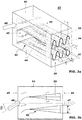
- Figure 2 shows a perspective view of a flow straightener and mixer 43 comprising two streamlined bodies 22 with lobes 28, 29 on the trailing edges, which are arranged inside a structure comprising 4 limiting walls 44, which form a rectangular flow path with an inlet area 45 and an outlet area 46.
- the lobes 28, 29 on the streamlined bodies 22 have essentially the same periodicity ⁇ but out of phase, i.e. the number of lobes at the trailing edge of each streamlined body 22 is identical and the lobes on neighboring streamlined bodies 22 are arranged in out of phase.
- the phases are shifted by 180°, i.e. the lobes of both streamlined bodies 22 cross the center line at the same position in longitudinal direction, and at the same position in longitudinal direction the deflection of each body has the same absolute value but is in opposite direction.
- the flow path through the flow straightener and mixer 43 is parallel to the limiting walls 44 and guiding the flow in a direction practically parallel to the longitudinal axis 47 of the flow straightener and mixer 43.
- the streamlined bodies 22 have a longitudinal axis 49, which are arranged normal to the longitudinal axis 47 of the flow straightener and mixer 23 and normal to the inlet flow direction 48, which in this example is parallel to the longitudinal axis 47. To assure good mixing a flow field with turbulent dissipation is induced over the complete cross section of the flow path by arranging two or more streamlined bodies 22 in the flow path.
- Fig. 3a shows a perspective view of a flow straightener and mixer 43 comprising two streamlined bodies 22 with lobes on the trailing edges, which are arranged inside a structure comprising 4 limiting walls 44, which form a rectangular flow path with an inlet area 45 and an outlet area 46.
- the lobes on the streamlined bodies 22 are arranged out of phase, in particular the phases are shifted by 180°, i.e. lobes of both streamlined bodies cross the center line at the same position in longitudinal direction, and at the same position in longitudinal direction the deflection the deflection of each body has the same absolute value but is in opposite direction.
- the streamlined bodies 22 are configured to redirect the main flow, which enters the flow straightener and mixer 43 under an inlet angle in the inlet flow direction 48 to a flow direction, which is substantially parallel to the longitudinal axis 47 of the flow straightener and mixer 23, therefore effectively turning the main flow by the inlet angle ⁇ .
- FIG. 3b A side view of the flow straightener and mixer 43 comprising two streamlined bodies 22 with lobes on the trailing edges is shown in Fig. 3b .
- the lobes extend with a constant lobe angle ⁇ 1 , ⁇ 2 in axial direction.
- the lobes start practically parallel to the main flow direction and the lobe angle ⁇ 1 , ⁇ 2 is gradually increasing in flow direction.
- Fig. 3b shows the inlet angle ⁇ , by which the main flow is turned in the flow straightener and mixer 43.
- the streamlined bodies 22 are inclined in the direction of the inlet flow 48 and under an angle to the longitudinal axis 47 at the inlet region and are turned in a direction substantially parallel to the longitudinal axis 47 at the outlet region of the flow straightener and mixer 43.
- FIG 4 streamlined bodies 22 of a flow straightener and mixer are shown from a downstream end.
- Figure 4 a) shows an arrangement with lobes on neighboring streamlined bodies 22 arranged in phase with each other
- figure 4 b) shows an arrangement with lobes on neighboring streamlined bodies 22 out of phase as.
- the resulting pattern of turbulent dissipation is shown in figures 4 c) and d ).
- Figure 4 d) shows the resulting pattern of turbulent dissipation for the further improved arrangement of figure 4 b) with lobes on neighboring streamlined bodies 22 arranged out of phase.
- turbulent vortex dissipation is created in a planes essentially normal to central planes 35, which are most pronounced at the location of maximum deflection.
- turbulent vortex dissipation are generated parallel to central planes 35 of streamlined bodies 22 in the region between two neighboring streamlined bodies 22 and between streamlined bodies 22 and limiting sidewalls. Due to the turbulent vortex dissipation in two directions, it is assured that a homogeneous mixture can be obtained for all possible inlet conditions.
- Homogeneous mixing of fuel and combustion air with minimum pressure drop are preconditions for the design of highly efficient modern gas turbines. Homogeneous mixing is required to avoid local maxima in the flame temperature, which lead to high NOx emissions. Low pressure drops are advantageous because the pressure drop in the combustor is directly impairing power and efficiency of a gas turbine.
- a gas turbine burner comprising the disclosed flow straightener and mixer 43 enables homogeneous mixing with low pressure drop.
- FIG. 5 shows a conventional secondary burner 1.
- the burner which is an annular burner, is bordered by opposite walls 3. These opposite walls 3 define the flow space for the flow 14 of oxidizing medium.
- This flow enters as a main flow 8 from the high pressure turbine, i.e. behind the last row of rotating blades of the high pressure turbine, which is located downstream of the first combustor.
- This main flow 8 enters the burner at the inlet side 6.
- First this main flow 8 passes flow-conditioning elements 9, which are typically stationary turbine outlet guide vanes, which bring the flow into the proper orientation. Downstream of these flow conditioning elements 9 vortex generators 10 are located in order to prepare for the subsequent mixing step.
- an injection device or fuel lance 7 which typically comprises a stem or foot 16 and an axial shaft 17. At the most downstream portion of the shaft 17 fuel injection takes place, in this case fuel injection takes place via orifices, which inject the fuel in a direction perpendicular to flow direction 14 (cross flow injection). Downstream of the fuel lance 7 there is the mixing zone 2, in which the air, bordered by the two walls 3, mixes with the fuel and then at the outlet side 5 exits into the combustion chamber or combustion space 4 where self-ignition takes place.
- transition 13 which may be in the form of a step, or as indicated here, may be provided with round edges and also with stall elements for the flow.
- the combustion space is bordered by the combustion chamber wall 12.
- FIG 6 a second fuel injection is illustrated, here the fuel lance 7 is not provided with conventional injection orifices but in addition to their positioning at specific axial and circumferential positions has circular sleeves protruding from the cylindrical outer surface of the shaft 17 such that the injection of the fuel along injection direction 26 is more efficient as the fuel is more efficiently directed into the vortices generated by the vortex generators 10.
- the present invention relates to burning of fuel air mixtures with a low ignition delay time. This is achieved by an integrated approach, which allows higher velocities of the main flow and in turn, a lower residence time of the fuel air mixture in the mixing zone.
- the challenge regarding the fuel injection is twofold with respect to the use of hydrogen rich fuels and fuel air mixtures with high temperatures:
- the conditions which the presented invention wants to address are those where the reactivity as defined above is above 1 and the flames are auto igniting, the invention is however not limited to these conditions.
- the main goal of this invention is to evolve an improved burner configuration, wherein the latter two points are addressed, which however can be combined also with the upper three points.
- the injector is designed to perform
- FIG 7 shows a set-up, where the proposed burner area is reduced considerably. The higher burner velocities help in operating the burner safely at highly reactive conditions.
- a proposed burner is shown with reduced exit cross-section area.
- a flow conditioning element or a row of flow conditioning elements 9 but in this case not followed by vortex generators but then directly followed with a fuel injection device according to the invention, which is given as a streamlined body 22 extending with its longitudinal direction across the two opposite walls 3 of the burner.
- the two walls 3 converge in a converging portion 18 and narrow down to a reduced burner cross-sectional area 19.
- the streamlined body 22 is configured as flute 22, which is illustrated in a cut in figure 8a , in side view in figure 8b , in a view onto the trailing edge against the main flow direction 14 in 5c and in a perspective view in figure 8d .
- the streamlined body 22 has a leading edge 25 and a trailing edge 24.
- the leading edge 25 defines a straight line and in the leading edge portion of the shape the shape is essentially symmetric, so in the upstream portion the body has a rounded leading edge and no lobing.
- the leading edge 25 extends along the longitudinal axis 49 of the flute 22. Downstream of this upstream section the lobes successively and smoothly develop and grow as one goes further downstream towards the trailing edge 24. In this case the lobes are given as half circles sequentially arranged one next to the other alternating in the two opposite directions along the trailing edge, as particularly easily visible in figure 8c .
- each turning point 27 which is also located on the central plane 35, there is located a fuel nozzle which injects the fuel inline, so essentially along the main flow direction 14.
- the trailing edge is not a sharp edge but has width W, which is for example in the range of 5 to 10 mm.
- the maximum width W of the flute element 22 is in the range of 25-35 mm and the total height h of the lobing is only slightly larger than this width W.
- a streamlined body for a typical burner in this case has a height H in the range of 100-200 mm.
- the periodicity ⁇ is around 40-60 mm.
- Figure 9 shows views against the main flow onto the trailing edge of lobed flutes 22 with different nozzle arrangements according to the invention.
- Figure 9a shows an arrangement where first nozzles 51 for injection of liquid fuel, are enclosed by second nozzles 52 for injection of a gaseous fuel, which themselves are encloses by third nozzles 53 for injection of carrier air.
- the nozzles 51, 52, 53 are arranged concentrically at the trailing edge. Each nozzle arrangement is located where the lobed trailing edge crosses the center plane 35.
- Figure 9c shows an arrangement where a second nozzle 52 for fuel gas injection is configured as one slit- like nozzle extending along at least one lobe along the trailing edge.
- additional first nozzles 51 in the form of orifices are arranged in the second nozzles 52.
- FIG 10 a view against the main flow direction 14 in the burner into the chamber where there is the converging portion 18 is shown.
- Three bodies in the form of lobed injectors 22 are arranged in this cavity and the central body 22 is arranged essentially parallel to the main flow direction, while the two lateral bodies 22 are arranged in a converging manner adapted to the convergence of the two side walls 18.
- Top and bottom wall in this case are arranged essentially parallel to each other, they may however also converge towards the mixing section.
- the height of the lobbing can be adapted (also along the trailing edge of one flute the height may vary).
- a burner similar to the one illustrated in figure 10 is given in a top view with the cover wall removed.
- the lateral two bodies 22 are arranged in a converging manner so that the flow is smoothly converging into the reduced cross sectional area towards the mixing space 2 bordered by the side wall at the reduced burner cross sectional area 19. Further the lobe height h of streamlined body 22 is bigger than in the example of figure 10 .
- the flame is typically located at the exit of this area 19, so at the outlet side 5 of the burner.
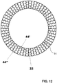
- FIG. 12 shows an annular burner comprising streamlined bodies 22 with lobed trailing edges 24, which are radially arranged between an inner wall 44' and outer wall 44" in a view against the main flow direction.
- the lobes 42 of neighboring streamlined bodies 22 are arranged out of phase.
- the number of streamlined bodies 22 is even to allow an alternating orientation of lobes of all neighboring streamlined elements, when closing the circle.
Description
- The present invention relates to a burner for a combustion chamber of a gas turbine comprising a combined flow straightener and mixer, with an injection device for the introduction of at least one gaseous and/or liquid.
- Mixing devices are needed for various technical applications. Optimization of mixing devices aims at reducing the energy required to obtain a specified degree of homogeneity. In continuous flow mixing the pressure drop over a mixing device is a measure for the required energy. Further, the time and space required to obtain the specified degree of homogeneity are important parameters when evaluating mixing devices or mixing elements. Static mixers are typically used for mixing of two continuous fluid streams.
- High volume flows of gas are for example mixed at the outlet of turbofan engines, where the hot exhaust gases of the core engine mix with relatively cold and slower bypass air. In order to reduce the sound emissions caused by these different flows lobe mixers were suggested for example in
US4401269 . - One specific application for mixing of continuous flow streams is the mixing of a fuel with an oxidizing fluid, for example air, in a burner for premixed combustion in a subsequent combustion chamber. In modern gas turbines good mixing of fuel and combustion air is a prerequisite for complete combustion with low emissions.
- In order to achieve a high efficiency, a high turbine inlet temperature is required in standard gas turbines. As a result, there arise high NOx emission levels and higher life cycle costs. These problems can be mitigated with a sequential combustion cycle, wherein the compressor delivers nearly double the pressure ratio of a conventional one. The main flow passes the first combustion chamber (e.g. using a burner of the general type as disclosed in
EP 1 257 809US 4,932,861 , also called EV combustor, where the EV stands for Environmental), wherein a part of the fuel is combusted. After expanding at the high-pressure turbine stage, the remaining fuel is added and combusted (e.g. using a burner of the type as disclosed inUS 5,431,018 orUS 5,626,017 or inUS 2002/0187448 , also called SEV combustor, where the S stands for sequential). Both combustors contain premixing burners, as low NOx emissions require high mixing quality of the fuel and the oxidizer. - Since the second combustor is fed by the expanded exhaust gas of the first combustor, the operating conditions allow self ignition (spontaneous ignition) of the fuel air mixture without additional energy being supplied to the mixture. To prevent ignition of the fuel air mixture in the mixing region, the residence time therein must not exceed the auto ignition delay time. This criterion ensures flame-free zones inside the burner. This criterion poses challenges in obtaining appropriate distribution of the fuel across the burner exit area. SEV-burners are currently only designed for operation on natural gas and oil. Therefore, the momentum flux of the fuel is adjusted relative to the momentum flux of the main flow so as to penetrate in to the vortices. This is done using air from the last compressor stage (high-pressure carrier air). The high-pressure carrier air is bypassing the high-pressure turbine. The subsequent mixing of the fuel and the oxidizer at the exit of the mixing zone is just sufficient to allow low NOx emissions (mixing quality) and avoid flashback (residence time), which may be caused by auto ignition of the fuel air mixture in the mixing zone.
- The invention is a burner according to
claim 1, a method according toclaim 11 and a use according toclaim 13. It is an object of the present invention to provide a highly effective mixer with a low pressure drop. As an application of such a mixer a burner comprising such a mixer is disclosed. Such a burner is particularly advantageous for high reactivity conditions, i.e. either for a situation where the inlet temperature of a burner is high, and/or for a situation where high reactivity fuels, specifically MBtu fuels, shall be burned in such burner. - First of all a mixer, which produces a mixture with a high homogeneity using only a minimum pressure drop, is proposed. Further, a burner with such a mixer is proposed. Such a burner is proposed to increase the gas turbine engine efficiency, to increase the fuel capability as well as to simplify the design.
- The objectives are achieved by providing a flow straightener and mixing device comprising a structure with limiting walls having a longitudinal axis an inlet area, and an outlet area in the main flow direction. For the combined function of flow straightening and mixing at least two streamlined bodies are arranged in the structure. Each streamlined body has a streamlined cross-sectional profile, which extends with a longitudinal direction perpendicularly or at an inclination to a main flow direction, which prevails in the flow straightener and mixing device. The leading edge area of each streamlined body has a profile, which is oriented parallel to a main flow direction prevailing at the leading edge position, and wherein, with reference to a central plane of the streamlined bodies the trailing edges are provided with at least two lobes in opposite transverse directions. It has been found that inverting the traverse deflection from the central plane of two adjacent streamlined bodies, which form the lobes, is particularly advantageous for efficient and fast mixing. In other words the periodic deflections from two adjacent streamlined bodies are out of phase: at the same position in longitudinal direction the deflection of each body has the same absolute value but is in opposite direction. Further, to minimize the pressure drop and to avoid any wakes the transition from a planar leading edge region to the deflections is smooth with a surface curvature representing a function with a continuous first derivative.
- Streamlined bodies with a combination of a leading edge area with an aerodynamic profile for flow straightening and with a lobed trailing edge for mixing is especially advantageous for mixing of flows with an inhomogeneous flow profile at the inlet area. Without the flow straightening the turbulent dissipation pattern created by the lobes is disturbed and only partial mixing takes place.
- The aerodynamic profile typically comprises a leading edge region with a round leading edge, and a thickness distribution with a maximum thickness in the front half of the profile. In one embodiment the rear section has a constant thickness distribution. The rear section with constant thickness distribution extends for example at least 30% of the profile length from the trailing edge. In a further embodiment the rear section with constant thickness distribution extends 50% or even up to 80% of the profile length.
- Additionally the rear section with constant thickness distribution can comprise the lobed section.
- The lobes alternatingly extend out of the central plane, i.e. in the transverse direction with respect to the central plane. The shape can be a sequence of semi-circles, sectors of circles, it can be in a sinus or sinusoidal form, it may also be in the form of a combination of sectors of circles or sinusoidal curves and adjunct straight sections, where the straight sections are asymptotic to the curves or sectors of circles. Preferentially, all lobes are of essentially the same shape along the trailing edge. The lobes are arranged adjacent to each other so that they form an interconnected trailing edge line. The lobe angles should be chosen in such a way that flow separation is avoided. According to one embodiment lobe angles (α1, α2) are between 15° and 45°, preferably between 25° and 35° to avoid flow separation.
- According to a preferred embodiment, the trailing edge is provided with at least 3, preferably at least 4 lobes sequentially arranged one adjacent to the next along the trailing edge, and alternatingly lobing in the two opposite transverse directions.
- A further preferred embodiment is characterized in that the streamlined body comprises an essentially straight leading edge. The leading edge may however also be rounded, bent or slightly twisted.
- According to a further preferred embodiment, the streamlined body, in its straight upstream portion with respect to the main flow direction, has a maximum width. Downstream of this width W the width, i.e. the distance between the lateral sidewalls defining the streamlined body, essentially continuously diminishes towards the trailing edge (the trailing edge either forming a sharp edge or rounded edge). The height, defined as the distance in the transverse direction of the apexes of adjacent lobes, is in this case preferentially at least half of the maximum width. According to one particular preferred embodiment, this height is approximately the same as the maximum width of the streamlined body. According to another particular preferred embodiment, this height is approximately twice the maximum width of the streamlined body. Generally speaking, preferentially the height is at least as large as the maximum width, preferably not more than three times as large as the maximum width.
- According to an embodiment the flow straightener and mixing device's the streamlined bodies comprises an essentially straight leading edge.
- A flow, which is practically parallel to the longitudinal axis of the mixer, which is aligned with the central plane of the lobed section of the streamlined body, is advantageous to optimize the flow conditions for the lobe mixing. To guide the flow in the parallel direction the leading edge region of the streamlined body has an aerodynamic profile, which is turning from an inclined orientation relative to the longitudinal axis of flow straightener and mixing device, to an orientation, which is parallel to the longitudinal axis of flow straightener and mixing device. This change in orientation preferably takes place in the upstream half of the streamlined body.
- According to a further preferred embodiment, the transverse displacement of the streamlined body forming the lobes is only at most in the downstream two thirds of the length 1 (measured along the main flow direction) of the streamlined body. This means that the upstream portion the streamlined body has an essentially symmetric shape with respect to the central plane. Downstream thereof the lobes are continuously and smoothly growing into each transverse direction forming a wavy shape of the sidewalls of the streamlined body where the amplitude of this wavy shape is increasing the maximum value at the trailing edge.
- According to one embodiment, the distance between the central planes of two streamlined bodies is at least 1.2 times the height of the lobes, preferably at least 1.5 times the height of the lobes in order to optimize the flow pattern in the mixer, and to allow mixing normal to the central planes of two streamlined bodies as well as parallel to the central planes of two streamlined bodies,
- According to a further embodiment the flow straightener and mixing device has a rectangular or trapezoidal cross section extending along the longitudinal axis. It is defined by four limiting walls, and comprises at least two streamlined bodies, which extend from one limiting wall to an opposing limiting wall, and which comprise at least two lobes in opposite transverse directions and wherein the traverse deflection from the central plane of two adjacent streamlined bodies are inverted.
- According to a further embodiment the flow straightener and mixing device has an annular cross section, which extends along the longitudinal axis of the flow straightener and mixing device with an inner limiting wall and an outer limiting wall, which are concentric to each other. At least two streamlined bodies extend from the inner limiting wall to the outer limiting wall, and which comprise at least two lobes in opposite transverse directions and wherein the traverse deflection from the central plane of two adjacent streamlined bodies are inverted.
- A specific objective of the invention is to provide a burner with improved mixing. This object is achieved by providing a burner, in particular (but not exclusively) for a secondary combustion chamber of a gas turbine with sequential combustion having a first and a second combustion chamber, with an injection device for the introduction of at least one gaseous and/or liquid fuel into the burner, wherein the injection device has at least one body which is arranged in the burner with at least one nozzle for introducing the at least one fuel into the burner. The at least one body is configured as a streamlined body which has a streamlined cross-sectional profile and which extends with a longitudinal direction perpendicularly or at an inclination to a main flow direction prevailing in the burner. The at least one nozzle has its outlet orifice at or in a trailing edge (or somewhat downstream of the trailing edge) of the streamlined body. According to the invention, such a streamlined body is formed such that with reference to a central plane of the streamlined body the trailing edge is provided with at least two lobes in opposite transverse directions.
- In other words the trailing edge does not form a straight line but a wavy or sinusoidal line, where this line oscillates around the central plane. The present invention involves injection of fuel at the trailing edge of the lobed injectors. The fuel injection is preferably along the axial direction, which eliminates the need for high-pressure carrier air.
- The invention allows fuel-air mixing with low momentum flux ratios being possible. An inline fuel injection system includes number of lobed flutes staggered to each other.
- The burner can be used for fuel-air mixing as well as mixing of fuel with any kind of gas used in closed or semi- closed gas turbines or with combustion gases of a first combustion stage.
- These burners can be used for gas turbines comprising one compressor, one combustor and one turbine as well as for gas turbines with one or multiple compressors, at least two combustors and at least two turbines. They can for example be used as premix burners in a gas turbine with one combustor or also be used as a reheat combustor for a secondary combustion chamber of a gas turbine with sequential combustion having a first and a second combustion chamber, with an injection device for the introduction of at least one gaseous and/or liquid fuel into the burner.
- The burner can be of any cross- section like basically rectangular or circular where typically a plurality of burners is arranged coaxially around the axis of a gas turbine. The burner cross section is defined by a limiting wall, which for example forms a can like burner. At least two streamlined bodies extend from one side of the limiting wall to an opposing side of the limiting wall, and which comprise at least two lobes in opposite transverse directions and wherein the traverse deflection from the central plane of two adjacent streamlined bodies are inverted. Fuel can be injected into the burner from at leas one of the streamlined bodies.
- In another embodiment the burner is arranged as an annular burner. In this embodiment the burner has an annular cross section, which extends along the longitudinal axis of the flow straightener and mixing device with an inner limiting wall and an outer limiting wall, which are concentric to each other. At least two streamlined bodies extend from the inner limiting wall to the outer limiting wall, and which comprise at least two lobes in opposite transverse directions and wherein the traverse deflection from the central plane of two adjacent streamlined bodies are inverted. Fuel can be injected into the burner from at least one of the streamlined bodies.
- The invention allows reduced pressure losses by an innovative injector design. The advantages are as follows:
- Increased GT efficiency
- ∘ The overall GT efficiency increases. The cooling air bypasses the high-pressure turbine, but it is compressed to a lower pressure level compared to normally necessary high-pressure carrier air and requires less or no cooling.
- ∘ Lobes can be shaped to produce appropriate flow structures. Intense shear of the vortices helps in rapid mixing and avoidance of low velocity pockets. An aerodynamically favored injection and mixing system reduces the pressure drop even further. Due to only having one device (injector) rather than the separate elements i) large-scale mixing device at the entrance of the burner, ii) vortex generators on the injector, and iii) injector pressure is saved. The savings can be utilized in order to increase the main flow velocity, which is beneficial if it comes to fuel air mixtures with high reactivity or can be utilized to increase the gas turbine performance.
- The fuel may be injected in-line right at the location where the vortices are generated. The design of the cooling air passage can be simplified, as the fuel does not require momentum from high-pressure carrier air anymore.
- One of the gists of the invention here is to merge the vortex generation aspect and the fuel injection device as conventionally used according to the state-of-the-art as a separate elements (separate structural vortex generator element upstream of separate fuel injection device) into one single combined vortex generation and fuel injection device. By doing this, mixing of fuels with oxidation air and vortex generation take place in very close spatial vicinity and very efficiently, such that more rapid mixing is possible and the length of the mixing zone can be reduced. It is even possible in some cases, by corresponding design and orientation of the body in the oxidizing air path, to omit the flow conditioning elements (turbine outlet guide vanes) as the body may also take over the flow conditioning. All this is possible without severe pressure drop along the injection device such that the overall efficiency of the process can be maintained or improved.
- Typically, in particular for gas turbine applications, the streamlined body has a height H along its longitudinal axis (perpendicular to the main flow) in the range of 100-200 mm. In particular under the circumstances, the lobe periodicity ("wavelength") λ is preferentially in the range of 20-100mm, preferably in the range of 30-60mm. This means that along the trailing edge there are located six alternating lobes, three in each transverse direction.
- According to the invention at least two, preferably at least three, more preferably at least four or five fuel nozzles are located at the trailing edge and distributed (preferentially in equidistant manner) along the trailing edge.
- According to the invention the fuel nozzles are located essentially on the central plane of the streamlined body (so typically not in the lobed portions of the trailing edge). In this case, a fuel nozzle is preferably located at each position or every second position along the trailing edge, where the lobed trailing edge crosses the central plane and/or the fuel nozzles are located essentially at the apexes of lobes, wherein a fuel nozzle is located at each apex or every second apex along the trailing edge.
- Such a burner is usually bordered by burner sidewalls. Typically the sidewalls are essentially planar wall structures, which can be converging towards the exit side. In particular (but not only) those sidewalls which are essentially parallel to the main axis of the lobed injection device(s) can, in accordance with yet another preferred embodiment, also be lobed so they can have an undulated surface. This undulation can, even more preferably, be essentially the same characteristics as the one of the injectors, i.e. the undulation can in particular be are inverted to the undulation of neighboring streamlined bodies, i.e. the may be arranged out of phase with the undulations of the injector(s). It may also have essentially the same height of the undulations as the height of the lobes of the injectors. So it is possible to have a structure, in which one lobed injector is bordered by at least one, preferably two lateral sidewalls of the combustion chamber, which have the same undulation characteristics, so that the flow path as a whole has the same lateral width as a function of the height. In other words the lateral distance between the sidewall and the trailing edge of the injector is essentially the same for all positions when going along the longitudinal axis of the injector.
- Preferentially, downstream of said body (typically downstream of a group of for example three of such bodies located within the same burner) a mixing zone is located, and at and/or downstream of said body the cross-section of said mixing zone is reduced, wherein preferably this reduction is at least 10%, more preferably at least 20%, even more preferably at least 30%, compared to the flow cross-section upstream of said body. Typically, at least the nozzle injects fuel (liquid or gas) and/or carrier gas parallel to the main flow direction. At least one nozzle may however also inject fuel and/or carrier gas at an inclination angle of normally not more than 30° with respect to the main flow direction. Preferably, the streamlined body extends across the entire flow cross section between opposite walls of the burner.
- Further, preferably the burner is a burner comprising at least two, preferably at least three streamlined bodies the longitudinal axes of which are arranged essentially parallel to each other. In this case normally only the central streamlined body has its central plane arranged essentially parallel to the main flow direction, while the two outer streamlined bodies are slightly inclined converging towards the mixing zone. This in particular if the mixing zone have the same converging shape.
- According to a preferred embodiment, the body is provided with cooling elements, wherein preferably these cooling elements are given by internal circulation of cooling medium along the sidewalls of the body (i.e. by providing a double wall structure) and/or by film cooling holes, preferably located near the trailing edge, and wherein most preferably the cooling elements are fed with air from the carrier gas feed also used for the fuel injection. For a gas turbine with sequential combustion, preferably the fuel is injected from the nozzle together with a carrier gas stream, and the carrier gas air is low pressure air with a pressure in the range of 10-25 bar, preferably in the range of 16- 22 bar.
- As mentioned above, it is preferred if streamlined body has a cross-sectional profile which, in the portion where it is not lobed, is mirror symmetric with respect to the central plane of the body for application with axial inflow.
- The streamlined body can be arranged in the burner such that a straight line connecting the trailing edge to a leading edge extends parallel to the main flow direction of the burner.
- A plurality of separate outlet orifices of a plurality of nozzles can be arranged next to one another and arranged at the trailing edge.
- At least one slit-shaped outlet orifice can be, in the sense of a nozzle, arranged at the trailing edge. A split-shaped or elongated slot nozzle is typically arranged to extend along the trailing edge of the streamlined body.
- The nozzles can comprise multiple outlet orifices for different fuel types and carrier air. In one embodiment a first nozzle for injection of liquid fuel or gas fuel, and a second nozzle for injection of carrier air, which encloses the first nozzle, are arranged at the trailing edge. In another embodiment a first nozzle for injection of liquid fuel, a second nozzle for injection of a gaseous fuel, which encloses the first nozzle, and a third nozzle for injection of carrier air, which encloses the first nozzle, and the second nozzle, are arranged at the trailing edge.
- Besides an improved burner comprising the flow straightener and mixer a method for operation of such a burner is an objective of the invention. Depending on the operating conditions, and load point of a gas turbine, the fuel flow injected trough a burner varies in a wide range. A simple operation where the flow is equally distributed to all burner nozzles and the flow through each nozzle is proportional to the total flow can lead to very small flow velocities at individual nozzles impairing the injection quality and penetration depth f the fuel into the air flow.
- According to one embodiment of the operating method the number of fuel injection nozzles trough which fuel is injected is determined as function of the total injected fuel flow in order to assure a minimum flow in the operative nozzles.
- In another embodiment the fuel is injected through every second fuel nozzle of a vane at low fuel flow rates. Alternatively the fuel is only injected through the fuel nozzles of every second or third vane of the burner. Further, the combination of both methods to reduce fuel injection is suggested: For low fuel mass flows the fuel is injected trough every second or third fuel nozzle of a vane and only through the fuel nozzles of every second or third vane of the burner is proposed. At an increased mass flow the number of vanes used for fuel injection and then the number of nozzles used for fuel injection per vane can be increased.
- Alternatively, at an increased mass flow the number of nozzles used for fuel injection per vane can be increased and then the number of vanes used for fuel injection and can be increased. Activation and deactivation of nozzles can for example be determined based on corresponding threshold fuel flows.
- Furthermore the present invention relates to the use of a burner as defined above for the combustion under high reactivity conditions, preferably for the combustion at high burner inlet temperatures and/or for the combustion of MBtu fuel, normally with a calorific value of 5000-20,000 kJ/kg, preferably 7000-17,000 kJ/kg, more preferably 10,000-15,000 kJ/kg, most preferably such a fuel comprising hydrogen gas.
- Referring to a first use of a flow straightener and mixing device for at least one burner for a combustion chamber the gas turbine group consists, as an autonomous unit, of a compressor, a first combustion chamber connected downstream of the compressor, a first turbine connected downstream of this combustion chamber, a second combustion chamber connected downstream of this turbine and a second turbine connected downstream of this combustion chamber. The turbomachines, namely compressor, first and second turbines, have preferably a single rotor shaft, and itself is supported at least two bearings. The first combustion chamber, which is configured as a self-contained annular combustion chamber, is accommodated in a casing. At its front end, the annular combustion chamber has a number of burners distributed on the periphery and these maintain the generation of hot gas. The hot gases from this annular combustion chamber act on the first turbine immediately downstream, whose thermally expanding effect on the hot gases is deliberately kept to a minimum, i.e. this turbine will consequently consist of not more than two rows of rotor blades. The hot gases which are partially expanded in the first turbine and which flow directly into the second combustion chamber have, for reasons presented, a very high temperature and the layout is preferably specific to the operation in such a way that the temperature will still be reliably around 900° - 1000°C. This second combustion chamber has no pilot burners or ignition devices. The combustion of fuel blown into the exhaust gases coming from the first turbine takes place here by means of self-ignition provided. In order to ensure a such self-ignition of a natural gas in the second combustion chamber, the outlet temperature of the gases from the first turbine must consequently still be very high, as presented above, and this must of course also be so during part-load operation. In order to ensure operational reliability and high efficiency in a combustion chamber designed for self-ignition it is eminently important for the location of the flame front to remain stable.
- Referring to a second use of a flow straightener and mixing device for at least one burner for a combustion chamber the gas turbine group consists, as an autonomous unit, of at least one compressor, at least one combustion chamber located downstream of the compressor, at least one turbine located downstream of the combustion chamber. The turbomachines, namely compressor and turbines, have preferably a single rotor shaft, and it is supported by at least two bearings. The combustion chamber comprising at least one combustion zone defines preferably an annular concept.
- Referring to third use of a flow straightener and mixing device for at least one burner for a combustion chamber of a gas turbine group, wherein the gas turbine group comprising at least one compressor, a plurality of cylindrical or quasi- cylindrical combustors arranged in an annular or quasi-annular array on a common rotor, and at least one turbine, wherein the combustor comprises at least a primary and secondary combustion zones. At the front end the primary combustion zone has a number of burners distributed on the periphery and these maintain the generation of hot gas. A quench zone, positioned downstream of the primary combustion zone, comprises for example a cooling air and/or a fuel ports, or a catalytic section, or a heat transfer arrangement. In this case the hot gases which are partially cooled in the quench zone and which flow directly into the second combustion zone have a very high temperature and the layout is preferably specific to the operation in such a way that the temperature will still be reliably around 900° - 1000°C. This second combustion zone has no pilot burners or ignition devices. The combustion of fuel blown into the exhaust gases coming from the quench zone takes place here by means of self-ignition provided.
- Further embodiments of the invention are laid down in the dependent claims.
- Preferred embodiments of the invention are described in the following with reference to the drawings, which are for the purpose of illustrating the present preferred embodiments of the invention and not for the purpose of limiting the same. In the drawings,
- Fig. 1
- shows in a) a schematic perspective view onto a lobed streamlined body and the flow paths generated on both sides and at the trailing edge thereof, and in b) a side elevation view thereof;
- Fig. 2
- shows a flow straightener and mixer comprising lobed streamlined bodies where lobes on neighboring streamlined bodies are arranged out of phase;
- Fig. 3
- shows in a) a schematic perspective view of a flow straightener and mixer comprising lobed streamlined bodies where lobes on neighboring streamlined bodies are arranged out of phase and configured to redirect the main flow and in b) a side view of the flow straightener and
mixer 43; - Fig. 4
- shows in a) streamlined bodies of a flow straightener and mixer from a downstream end with lobes on neighboring streamlined bodies arranged in phase with each other, and in b) out of phase as well as the resulting pattern of turbulent dissipation in c) and d);
- Fig. 5
- shows a secondary burner located downstream of the high-pressure turbine together with the fuel mass fraction contour (right side) at the exit of the burner;
- Fig. 6
- shows a secondary burner fuel lance in a view opposite to the direction of the flow of oxidizing medium in a) and the fuel mass fraction contour using such a fuel lance at the exit of the burner in b);
- Fig. 7
- shows a secondary burner located downstream of the high-pressure turbine with reduced exit cross-section area;
- Fig. 8
- shows a lobed flute according to the invention, wherein in a) a cut perpendicular to the longitudinal axis is shown, in b) a side view, in c) a view onto the trailing edge and against the main flow, and in d) a perspective view is shown;
- Fig. 9
- shows views against the main flow onto the trailing edge of lobed flutes with different nozzle arrangements according to the invention;
- Fig. 10
- shows in a view against the main flow direction;
- Fig. 11
- shows a burner according to the invention, in a top view with removed top cover;
- Fig. 12
- shows in a view against the main flow direction of an annular burner with lobed flutes radially arranged between an inner and outer wall of the burner.
- The lobed mixing concept is described with reference to
figure 1. Figure 1 shows the flow conditions along a streamlined body. Thecentral plane 35 of which is arranged essentially parallel to aflow direction 14 of an airflow, which has a straightleading edge 38 and alobed trailing edge 39. Theairflow 14 at the leading edge in a situation like that develops a flow profile as indicated schematically in the upper view with thearrows 14. - The
lobed structure 42 at the trailingedge 39 is progressively developing downstream the leadingedge 38 to a wavy shape with lobes going into afirst direction 30, which is transverse to thecentral plane 35, the lobe extending in thatfirst direction 30 is designated with thereference numeral 28. Lobes extending into a secondtransverse direction 31, so infigure 1a in a downward direction, are designating withreference numeral 29. The lobes alternate in the two directions and wherever the lobes or rather the line/plane forming the trailing edge pass thecentral plane 35 there is aturning point 27. - As one can see from the arrows indicated in
figure 1a , the airflow flowing in the channel-like structures on the upper face and the airflows in the channels on the lower face intermingle and start to generate vortexes downstream of the trailingedge 39 leading to an intensive mixing as indicated withreference numeral 41.Theses vortices 41 are useable for the injection of fuels/air as will be discussed further below. - The
lobed structure 42 is defined by the following parameters: - the periodicity λ gives the width of one period of lobes in a direction perpendicular to the
main flow direction 14; - the height h is the distance in a direction perpendicular to the
main flow direction 14, so along thedirections figure 1b . - the first lobe angle α1 (also called elevation angle) which defines the displacement into the first direction of the
lobe 28, and -
Figure 2 shows a perspective view of a flow straightener andmixer 43 comprising twostreamlined bodies 22 withlobes walls 44, which form a rectangular flow path with aninlet area 45 and anoutlet area 46. Thelobes streamlined bodies 22 have essentially the same periodicity λ but out of phase, i.e. the number of lobes at the trailing edge of eachstreamlined body 22 is identical and the lobes on neighboringstreamlined bodies 22 are arranged in out of phase. In particular the phases are shifted by 180°, i.e. the lobes of bothstreamlined bodies 22 cross the center line at the same position in longitudinal direction, and at the same position in longitudinal direction the deflection of each body has the same absolute value but is in opposite direction. - The flow path through the flow straightener and
mixer 43 is parallel to the limitingwalls 44 and guiding the flow in a direction practically parallel to thelongitudinal axis 47 of the flow straightener andmixer 43. Thestreamlined bodies 22 have alongitudinal axis 49, which are arranged normal to thelongitudinal axis 47 of the flow straightener andmixer 23 and normal to theinlet flow direction 48, which in this example is parallel to thelongitudinal axis 47. To assure good mixing a flow field with turbulent dissipation is induced over the complete cross section of the flow path by arranging two or morestreamlined bodies 22 in the flow path. - Lobes, which are arranged out of phase lead to a further improved mixing as is discussed in more detail with reference to
figure 4 . -
Fig. 3a shows a perspective view of a flow straightener andmixer 43 comprising twostreamlined bodies 22 with lobes on the trailing edges, which are arranged inside a structure comprising 4 limitingwalls 44, which form a rectangular flow path with aninlet area 45 and anoutlet area 46. As infigure 2 , infigure 3 the lobes on thestreamlined bodies 22 are arranged out of phase, in particular the phases are shifted by 180°, i.e. lobes of both streamlined bodies cross the center line at the same position in longitudinal direction, and at the same position in longitudinal direction the deflection the deflection of each body has the same absolute value but is in opposite direction. - The
streamlined bodies 22 are configured to redirect the main flow, which enters the flow straightener andmixer 43 under an inlet angle in theinlet flow direction 48 to a flow direction, which is substantially parallel to thelongitudinal axis 47 of the flow straightener andmixer 23, therefore effectively turning the main flow by the inlet angle β. - A side view of the flow straightener and
mixer 43 comprising twostreamlined bodies 22 with lobes on the trailing edges is shown inFig. 3b . In the examples shown the lobes extend with a constant lobe angle α1, α2 in axial direction. In other embodiments the lobes start practically parallel to the main flow direction and the lobe angle α1, α2 is gradually increasing in flow direction. - Further,
Fig. 3b shows the inlet angle β, by which the main flow is turned in the flow straightener andmixer 43. To turn the main flow thestreamlined bodies 22 are inclined in the direction of theinlet flow 48 and under an angle to thelongitudinal axis 47 at the inlet region and are turned in a direction substantially parallel to thelongitudinal axis 47 at the outlet region of the flow straightener andmixer 43. - In
figure 4 streamlined bodies 22 of a flow straightener and mixer are shown from a downstream end.Figure 4 a) shows an arrangement with lobes on neighboringstreamlined bodies 22 arranged in phase with each other, andfigure 4 b) shows an arrangement with lobes on neighboringstreamlined bodies 22 out of phase as. Further, the resulting pattern of turbulent dissipation is shown infigures 4 c) and d ). - In
Figure 4 c) the resulting pattern of turbulent dissipation for the arrangement offigure 4a with lobes on neighboringstreamlined bodies 22 arranged in phase with each other is shown. As a result of the lobes, which have deflections in phase from thecentral planes 35 of allstreamlined bodies 22, turbulent vortex dissipation is created in a planes essentially normal tocentral planes 35, which are most pronounced at the location of maximum deflection. With this arrangement a homogeneous mixture can be obtained if mixing is mainly required in one direction. -
Figure 4 d) shows the resulting pattern of turbulent dissipation for the further improved arrangement offigure 4 b) with lobes on neighboringstreamlined bodies 22 arranged out of phase. As a result of the lobes, which have deflections out of phase, turbulent vortex dissipation is created in a planes essentially normal tocentral planes 35, which are most pronounced at the location of maximum deflection. Additionally zones of high, turbulent vortex dissipation are generated parallel tocentral planes 35 ofstreamlined bodies 22 in the region between two neighboringstreamlined bodies 22 and betweenstreamlined bodies 22 and limiting sidewalls. Due to the turbulent vortex dissipation in two directions, it is assured that a homogeneous mixture can be obtained for all possible inlet conditions. - Homogeneous mixing of fuel and combustion air with minimum pressure drop are preconditions for the design of highly efficient modern gas turbines. Homogeneous mixing is required to avoid local maxima in the flame temperature, which lead to high NOx emissions. Low pressure drops are advantageous because the pressure drop in the combustor is directly impairing power and efficiency of a gas turbine.
- A gas turbine burner comprising the disclosed flow straightener and
mixer 43 enables homogeneous mixing with low pressure drop. - The advantages of this kind of burner are particularly big for burners, which burn high reactivity fuels and for burners with high combustor inlet temperatures such as Sequential EnVironmental burner (SEV).
- Therefore on the example of SEV burners several design modifications to the existing SEV designs are proposed to introduce a low pressure drop complemented by rapid mixing for highly reactive fuels and operating conditions. This invention targets towards accomplishing fuel-air mixing within short burner-mixing lengths. The concept includes aerodynamically facilitated axial fuel injection with mixing promoted by small sized vortex generators. Further performance benefit is achieved with elimination/replacement of high-pressure and more valuable carrier air with lower pressure carrier air. As a result, the burner is designed to operate at an increased SEV inlet temperature or fuel flexibility without suffering on high NOx emissions or flashback.
- The key advantages can be summarized as follows:
- Higher burner velocities to accommodate highly reactive fuels
- Lower burner pressure drop for similar mixing levels achieved with current designs
- SEV operable at higher inlet temperatures
- Possibility to remove or replace high-pressure carrier air with lower pressure carrier air
- With respect to performing a reasonable fuel air mixing, the following components of current burner systems are of interest:
- At the entrance of the SEV combustor, the main flow must be conditioned in order to guarantee uniform inflow conditions independent of the upstream disturbances, e.g. caused by the high-pressure turbine stage.
- Then, the flow must pass four vortex generators.
- For the injection of gaseous and liquid fuels into the vortices, fuel lances are used, which extend into the mixing section of the burner and inject the fuel(s) into the vortices of the air flowing around the fuel lance.
- To this end
figure 5 shows a conventionalsecondary burner 1. The burner, which is an annular burner, is bordered byopposite walls 3. Theseopposite walls 3 define the flow space for theflow 14 of oxidizing medium. This flow enters as amain flow 8 from the high pressure turbine, i.e. behind the last row of rotating blades of the high pressure turbine, which is located downstream of the first combustor. Thismain flow 8 enters the burner at theinlet side 6. First thismain flow 8 passes flow-conditioning elements 9, which are typically stationary turbine outlet guide vanes, which bring the flow into the proper orientation. Downstream of theseflow conditioning elements 9vortex generators 10 are located in order to prepare for the subsequent mixing step. Downstream of thevortex generators 10 there is provided an injection device orfuel lance 7, which typically comprises a stem orfoot 16 and anaxial shaft 17. At the most downstream portion of theshaft 17 fuel injection takes place, in this case fuel injection takes place via orifices, which inject the fuel in a direction perpendicular to flow direction 14 (cross flow injection). Downstream of thefuel lance 7 there is the mixingzone 2, in which the air, bordered by the twowalls 3, mixes with the fuel and then at theoutlet side 5 exits into the combustion chamber or combustion space 4 where self-ignition takes place. - At the transition between the mixing
zone 2 to the combustion space 4 there is typically atransition 13, which may be in the form of a step, or as indicated here, may be provided with round edges and also with stall elements for the flow. The combustion space is bordered by thecombustion chamber wall 12. - This leads to a fuel
mass fraction contour 11 at theburner exit 5 as indicated on the right side offigure 5 . - In
figure 6 a second fuel injection is illustrated, here thefuel lance 7 is not provided with conventional injection orifices but in addition to their positioning at specific axial and circumferential positions has circular sleeves protruding from the cylindrical outer surface of theshaft 17 such that the injection of the fuel alonginjection direction 26 is more efficient as the fuel is more efficiently directed into the vortices generated by thevortex generators 10. - Using a set-up according to
figure 6a , the fuel mass fraction contour according tofigure 6b results. - SEV-burners are currently designed for operation on natural gas and oil only. Therefore, the momentum of the fuel is adjusted relative to the momentum of the main flow so as to penetrate in to the vortices. The subsequent mixing of the fuel and the oxidizer at the exit of the mixing zone is just sufficient to allow low NOx emissions (mixing quality) and avoid flashback (residence time), which may be caused by auto ignition of the fuel air mixture in the mixing zone.
- The present invention relates to burning of fuel air mixtures with a low ignition delay time. This is achieved by an integrated approach, which allows higher velocities of the main flow and in turn, a lower residence time of the fuel air mixture in the mixing zone. The challenge regarding the fuel injection is twofold with respect to the use of hydrogen rich fuels and fuel air mixtures with high temperatures:
- Hydrogen rich fuels may change the penetration behavior of the fuel jets. The penetration is determined by the cross section areas of the burner and the fuel injection holes, respectively.
- The second problem is that depending on the type of fuel or the temperature of the fuel air mixture, the reactivity, which can be defined as tign,ref/tign, i.e. as the ratio of the ignition time of reference natural gas to the actual ignition time of the fuel air mixture changes.
- The conditions which the presented invention wants to address are those where the reactivity as defined above is above 1 and the flames are auto igniting, the invention is however not limited to these conditions.
- For each temperature and mixture composition the laminar flame speed and the ignition delay time change. As a result, hardware configurations must be provided offering a suitable operation window. For each hardware configuration, the upper limit regarding the fuel air reactivity is given by the flashback margin.
- In the framework of an SEV burner the flashback risk is increased, as the residence time in the mixing zone exceeds the ignition delay time of the fuel air. Mitigation can be achieved in several different ways:
- The inclination angle of the fuel can be adjusted to decrease the residence time of the fuel. Herein, various possibilities regarding the design may be considered, e.g. inline fuel injection, i.e. essentially parallel to the oxidizing airflow, a conical lance shape or a horny lance design.
- The reactivity can be slowed down by diluting the fuel air mixture with nitrogen or steam, respectively.
- De-rating of the first stage can lead to less aggressive inlet conditions for the SEV burner in case of highly reactive fuels. In turn, the efficiency of the overall gas turbine may decrease.
- The length of the mixing zone can be kept constant, if in turn the main flow velocity is increased. However, then normally a penalty on the pressure drop must be taken.
- By implementing more rapid mixing of the fuel and the oxidizer, the length of the mixing zone can be reduced while maintaining the main flow velocity.
- The main goal of this invention is to evolve an improved burner configuration, wherein the latter two points are addressed, which however can be combined also with the upper three points.
- In order to allow capability for highly reactive fuels, the injector is designed to perform
- flow conditioning (at least partial),
- injection and
- mixing
-
Figure 7 shows a set-up, where the proposed burner area is reduced considerably. The higher burner velocities help in operating the burner safely at highly reactive conditions. Infigure 7 a proposed burner is shown with reduced exit cross-section area. In this case downstream of theinlet side 6 of the burner there is located a flow conditioning element or a row offlow conditioning elements 9 but in this case not followed by vortex generators but then directly followed with a fuel injection device according to the invention, which is given as astreamlined body 22 extending with its longitudinal direction across the twoopposite walls 3 of the burner. At the position where thestreamlined body 22 is located the twowalls 3 converge in a convergingportion 18 and narrow down to a reduced burnercross-sectional area 19. This defines the mixingspace 2, which ends at theoutlet side 5 where the mixture of fuel and air enters the combustion chamber or combustion space 4, which is delimited bywalls 12. - This general concept of lobed mixers as described for
figure 1 is now applied to flute like injectors for a burner. -
Figure 8 shows the basic design resulting in a flute like injector. The injector can be part of a burner, as already described elsewhere. The main flow is passing the lobed mixer, resulting in velocity gradients. These result in intense generation of shear layers, into which fuel can be injected. The lobe angles are chosen in such way to avoid flow separation. - More specifically, the
streamlined body 22 is configured asflute 22, which is illustrated in a cut infigure 8a , in side view infigure 8b , in a view onto the trailing edge against themain flow direction 14 in 5c and in a perspective view infigure 8d . - The
streamlined body 22 has aleading edge 25 and a trailingedge 24. The leadingedge 25 defines a straight line and in the leading edge portion of the shape the shape is essentially symmetric, so in the upstream portion the body has a rounded leading edge and no lobing. The leadingedge 25 extends along thelongitudinal axis 49 of theflute 22. Downstream of this upstream section the lobes successively and smoothly develop and grow as one goes further downstream towards the trailingedge 24. In this case the lobes are given as half circles sequentially arranged one next to the other alternating in the two opposite directions along the trailing edge, as particularly easily visible infigure 8c . - At each
turning point 27 which is also located on thecentral plane 35, there is located a fuel nozzle which injects the fuel inline, so essentially along themain flow direction 14. In this case the trailing edge is not a sharp edge but has width W, which is for example in the range of 5 to 10 mm. The maximum width W of theflute element 22 is in the range of 25-35 mm and the total height h of the lobing is only slightly larger than this width W. - A streamlined body for a typical burner in this case has a height H in the range of 100-200 mm. The periodicity λ is around 40-60 mm.
-
Figure 9 shows views against the main flow onto the trailing edge oflobed flutes 22 with different nozzle arrangements according to the invention.Figure 9a shows an arrangement wherefirst nozzles 51 for injection of liquid fuel, are enclosed bysecond nozzles 52 for injection of a gaseous fuel, which themselves are encloses bythird nozzles 53 for injection of carrier air. Thenozzles center plane 35. -
Figure 9b shows an arrangement wheresecond nozzles 52 for fuel gas injection are configured as a slit- like nozzle extending along the trailing edge each at each apex section of the lobes. Additionallyfirst nozzles 51 for liquid fuel injection arranged at each location where the lobed trailing edge crosses thecenter plane 35. All the first andsecond nozzles third nozzles 53 for the injection of carrier air. -
Figure 9c shows an arrangement where asecond nozzle 52 for fuel gas injection is configured as one slit- like nozzle extending along at least one lobe along the trailing edge. For liquid fuel injection additionalfirst nozzles 51 in the form of orifices are arranged in thesecond nozzles 52. -
Figure 10 shows the lobed flute housed inside a reduced cross sectional area burner. The lobes are staggered in order to improve the mixing performance. The lobe sizes can be varied to optimize both pressure drop and mixing. - In
figure 10 a view against themain flow direction 14 in the burner into the chamber where there is the convergingportion 18 is shown. Three bodies in the form oflobed injectors 22 are arranged in this cavity and thecentral body 22 is arranged essentially parallel to the main flow direction, while the twolateral bodies 22 are arranged in a converging manner adapted to the convergence of the twoside walls 18. - Top and bottom wall in this case are arranged essentially parallel to each other, they may however also converge towards the mixing section.
- In the case of
figure 10 the lobing of the trailing edge is essentially similar to the one as illustrated infigure 8 . - Depending on the desired mixing properties, the height of the lobbing can be adapted (also along the trailing edge of one flute the height may vary).
- In
figure 11 a burner similar to the one illustrated infigure 10 is given in a top view with the cover wall removed. The lateral twobodies 22 are arranged in a converging manner so that the flow is smoothly converging into the reduced cross sectional area towards the mixingspace 2 bordered by the side wall at the reduced burner crosssectional area 19. Further the lobe height h ofstreamlined body 22 is bigger than in the example offigure 10 . The flame is typically located at the exit of thisarea 19, so at theoutlet side 5 of the burner. - Modern gas turbines typically have annular combustors. To realize an annular combustor a number of burners with a rectangular cross section as for example shown in
figures 5 ,7 ,10 and 11 can be arranged concentrically around the axis of a gas turbine. Typically they are equally distanced and form a ring like structure. A trapezoidal cross-section or cross section in the form of ring segments can also be used. - In a further embodiment an annular burner as shown in
figure 12 is proposed.Figure 12 shows an annular burner comprisingstreamlined bodies 22 with lobed trailingedges 24, which are radially arranged between an inner wall 44' andouter wall 44" in a view against the main flow direction. Thelobes 42 of neighboringstreamlined bodies 22 are arranged out of phase. Preferably the number ofstreamlined bodies 22 is even to allow an alternating orientation of lobes of all neighboring streamlined elements, when closing the circle. - The inner wall 44' and
outer wall 44" form an annular flow path. When in operation thestreamlined bodies 22 with lobed trailingedges 22 impose a turbulent dissipating flow field on the gases, with two main orientations of turbulent dissipation fields: one in radial direction, practically parallel to the streamlined bodies, 22 and in each case between twostreamlined body 22, and one normal to thestreamlined body 22 in circumferential direction concentric with the inner and outer walls 44 (not shown). In the example at least every second stream linedbody 22 is provided withfuel nozzles 15 to form lobed flutes 22. The resulting three-dimensional flow field assures a good mixing and creates a homogeneous fuel air mixture in a very short distance and time. - Several embodiments to the lobed fuel injection system are listed below:
- Embodiment 1:
Staggering of lobes to eliminate vortex-vortex interactions. The vortex-vortex interactions result in not effectively mixing the fuel air streams. - Embodiment 2:
Careful placement and location of fuel injection on the lobes: Fuel jets can be placed in the areas of high shear regions in order to best utilize the turbulent dissipation for mixing. - Embodiment 3:
Inclined fuel injection in the lobes: This allows fuel to be injected in to the vortex cores. - Embodiment 4:
Number of flute lobes inside the burner: The flutes can be varied to decide on the strength of the vortices. - Embodiment 5:
Fuel staging in the lobed fuel injectors to control emissions and pulsations. - The advantages of lobed injectors when compared to existing concepts can be summarized as follows:
- Better streamlining of hot gas flows to produce strong vortices for rapid mixing and low-pressure drops.
- The high speed shearing of fuel mixture can be utilized to control combustor pulsations and flame characteristics.
- The lobed flute injector is flexible offering several design variations.
- Rapid shear of fuel and air due to lobed structures results in enhanced mixing delivered with shorter burner mixing lengths.
- The work leading to this invention has received funding from the [European Community's] Seventh Framework Programme ([FP7/2007-2013) under grant agreement n° [211971].
LIST OF REFERENCE SIGNS 1 burner 17 shaft of 7 2 mixing space, mixing zone 18 converging portion of 3 3 burner wall 19 reduced burner cross-sectional area 4 combustion space 5 outlet side, burner exit 20 reduction in cross section 6 inlet side 21 entrance section of 3 7 injection device, fuel lance 22 streamlined body, flute 8 main flow from high-pressure turbine 23 lobed blade 24 trailing edge of 22, 23 9 flow conditioning, turbine outlet guide vanes 25 leading edge of 22, 23 26 injection direction 10 vortex generators 27 turning point 11 fuel mass fraction contour at burner exit 5 28 lobe in first direction 30 29 lobe in second direction 31 12 combustion chamber wall 30 first transverse direction 13 transition between 3 and 12 31 second transverse direction 14 flow of oxidizing medium 32 apex of 28,29 15 fuel nozzle 33 lateral surface of 22 16 foot of 7 34 ejection direction of fuel/carrier gas mixture 51 first nozzle 35 central plane of 22/23 52 second nozzle 38 leading edge of 24 53 third nozzle 39 trailing edge of 23 54 slot nozzle 40 flow profile 55 normal turbulent dissipation 41 vortex 56 parallel turbulent dissipation 42 lobes 43 flow straightener and mixer λ periodicity of 42 44 limiting walls h height of 42 44' inner limiting wall α1 first lobe angle 44" outer limiting wall α2 second lobe angle 45 inlet area β inlet angle 46 outlet area 1 length of 22 47 longitudinal axis of 43 H height of 22 48 inlet flow direction w width at trailing edge 49 longitudinal axis of 22 W maximum width of 22 50 central element
Claims (13)
- Burner (1) for a combustion chamber of a gas turbine with a flow straightener and mixing device (43) comprising a structure with limiting walls (44) having a longitudinal axis (47), an inlet area (45), and an outlet area (46) in the main flow direction, at least two streamlined bodies (22), which are arranged in the flow straightener and mixing device (43), each having a streamlined cross-sectional profile (48), which extends with a longitudinal direction (49) perpendicularly or at an inclination to a main flow direction (14) prevailing in the flow straightener and mixing device (43), wherein the leading edge area of each streamlined body (22) has a profile, which is oriented parallel to a main flow direction prevailing at the leading edge position, and wherein, with reference to a central plane (35) of the streamlined bodies (22) the trailing edges (24) are provided with at least two lobes (28, 29) in opposite transverse directions (30, 31) wherein the traverse deflection from the central plane of two adjacent streamlined bodies (22), which form the lobes (28, 29), are inverted, and in that the transition from a planar leading edge region to the deflections is smooth with a surface curvature representing a function with a continuous first derivative
characterized in that at least one of the streamlined bodies (22) is configured as an injection device with at least one nozzle (15) for introducing at least one fuel into the burner (1), wherein at least two fuel nozzles (15) which are located at the trailing edge (24) of at least one of the streamlined bodies (22) are located at the apexes (32) of lobes (28, 29), wherein at each apex (32) or at every second apex (32) along the trailing edge (24) there is located a fuel nozzle (15), and/or wherein fuel nozzles (15) are located on the central plane (35) of the streamlined body (22), wherein at each position, where the lobed trailing edge (24) crosses the central plane (35), there is located a fuel nozzle (15). - Burner (1) according to claim 1, characterized in that the leading edge region of the streamlined body (22) has an aerodynamic profile, which is turning from an inclined orientation relative to the longitudinal axis (47) of flow straightener and mixing devices (43) to an orientation, which is parallel to the longitudinal axis (47) of flow straightener and mixing device (43) in the upstream half of the streamlined body (22).
- Burner (1) according to any of the preceding claims, characterized in that the transverse displacement of the streamlined body forming the lobes (28, 29) is only at most in the downstream two thirds of the length (1) of the streamlined body (22), preferably only in the downstream half of the length (1) of the streamlined body (22).
- Burner (1) according to any of the preceding claims, characterized in that distance between the central planes (35) of two streamlined bodies (22) is at least 1.2 times the height (h) of the lobes (42), preferably at least 1.5 times the height (h) of the lobes (42).
- Burner (1) according to any of the preceding claims, characterized in that the flow straightener and mixing device (43) has a rectangular or trapezoidal cross section extending along the longitudinal axis (47), which is defined by four limiting walls (44), with the at least two streamlined bodies (22) extending from one limiting wall (44) to an opposing limiting wall (44).
- Burner (1) according to any of the claims 1 to 4, characterized in that the flow straightener and mixing device (43) has an annular cross section extending along the longitudinal axis (47) with an inner limiting wall (44') and an outer limiting wall (44") which are concentric to each other and with the at least two streamlined bodies (22) extending from the inner limiting wall (44') to the outer limiting wall (44").
- Burner (1) according any of the claims 1 to 6, characterized in that at least two fuel nozzles (15) are located at the trailing edge (24) of at least one of the streamlined bodies (22) and distributed along the trailing edge (24), wherein at least at one position, where the lobed trailing edge (24) crosses the central plane (35), there is located a fuel nozzle (15) for injection of a liquid fuel, and wherein at least one fuel nozzles (15) for injection of a gaseous fuel is located essentially at the turning points (27) between two lobes (28, 29).
- Burner (1) according to any of the claims 1 to 7, characterized in that downstream of said streamlined bodies (22) a mixing zone (2) is located, and wherein at and/or downstream of said streamlined bodies (22) the cross-section of said mixing zone (2) is reduced, wherein preferably this reduction is at least 10%, more preferably at least 20%, even more preferably at least 30%, compared to the flow cross-section upstream of said streamlined bodies (22).
- Burner (1) according to any of the claims 1 to 8, characterized in that the body (22) is provided with cooling elements, wherein preferably these cooling elements are given by internal circulation of cooling medium along the sidewalls of the body (22) and/or by film cooling holes, preferably located near the trailing edge (24), and wherein most preferably the cooling elements are fed with air from the carrier gas feed also used for the fuel injection.
- Burner (1) according to any of the claims 1 to 9, characterized in that the fuel nozzles (15) are circular and/or are elongated slot nozzles (54) extending along the trailing edge of the streamlined body (22) and/or comprise a first nozzle for injection of liquid fuel (51), and/or a second nozzle (52) for injection of a gaseous fuel and a third nozzle (53) for injection of carrier air, which encloses the first nozzle (51) and/or the second nozzle (52).
- Method for operating a burner (1) according to any of the claims 1 to 10, characterized in that the number of fuel injection nozzles through which fuel is injected is determined as function of the total injected fuel flow.
- Method for operating a burner (1) according to claim 11, characterized in that below a threshold fuel flow fuel is only injected trough every second fuel nozzle (15) of a streamlined body (22) and/or that fuel is only injected through the fuel nozzles of every second or third streamlined body (22) of the burner (1).
- Use of a burner (1) according to any of the claims 1 to 10 for the combustion under high reactivity conditions, preferably for the combustion at high burner inlet temperatures and/or for the combustion of MBtu fuel and/or for the combustion of hydrogen rich fuel.
Applications Claiming Priority (1)
| Application Number | Priority Date | Filing Date | Title |
|---|---|---|---|
| CH7952011 | 2011-05-11 |
Publications (2)
| Publication Number | Publication Date |
|---|---|
| EP2522912A1 EP2522912A1 (en) | 2012-11-14 |
| EP2522912B1 true EP2522912B1 (en) | 2019-03-27 |
Family
ID=46026741
Family Applications (1)
| Application Number | Title | Priority Date | Filing Date |
|---|---|---|---|
| EP12167781.9A Active EP2522912B1 (en) | 2011-05-11 | 2012-05-11 | Flow straightener and mixer |
Country Status (2)
| Country | Link |
|---|---|
| US (1) | US8938971B2 (en) |
| EP (1) | EP2522912B1 (en) |
Families Citing this family (52)
| Publication number | Priority date | Publication date | Assignee | Title |
|---|---|---|---|---|
| RU2550370C2 (en) * | 2011-05-11 | 2015-05-10 | Альстом Текнолоджи Лтд | Centrifugal nozzle with projecting parts |
| US8943832B2 (en) * | 2011-10-26 | 2015-02-03 | General Electric Company | Fuel nozzle assembly for use in turbine engines and methods of assembling same |
| CA2830031C (en) * | 2012-10-23 | 2016-03-15 | Alstom Technology Ltd. | Burner for a can combustor |
| EP2837782A1 (en) | 2013-08-14 | 2015-02-18 | Alstom Technology Ltd | Damper for combustion oscillation damping in a gas turbine |
| EP2837883B1 (en) * | 2013-08-16 | 2018-04-04 | Ansaldo Energia Switzerland AG | Premixed can annular combustor with mixing lobes for the second stage of a sequential gas turbine |
| EP2889542B1 (en) * | 2013-12-24 | 2019-11-13 | Ansaldo Energia Switzerland AG | Method for operating a combustor for a gas turbine and combustor for a gas turbine |
| US9528702B2 (en) | 2014-02-21 | 2016-12-27 | General Electric Company | System having a combustor cap |
| US9528704B2 (en) * | 2014-02-21 | 2016-12-27 | General Electric Company | Combustor cap having non-round outlets for mixing tubes |
| EP2933559A1 (en) * | 2014-04-16 | 2015-10-21 | Alstom Technology Ltd | Fuel mixing arragement and combustor with such a fuel mixing arrangement |
| EP2966350B1 (en) | 2014-07-10 | 2018-06-13 | Ansaldo Energia Switzerland AG | Axial swirler |
| EP3023696B1 (en) | 2014-11-20 | 2019-08-28 | Ansaldo Energia Switzerland AG | Lobe lance for a gas turbine combustor |
| EP3026344B1 (en) * | 2014-11-26 | 2019-05-22 | Ansaldo Energia Switzerland AG | Burner of a gas turbine |
| EP3029378B1 (en) * | 2014-12-04 | 2019-08-28 | Ansaldo Energia Switzerland AG | Sequential burner for an axial gas turbine |
| US10107498B2 (en) | 2014-12-11 | 2018-10-23 | General Electric Company | Injection systems for fuel and gas |
| US10094570B2 (en) | 2014-12-11 | 2018-10-09 | General Electric Company | Injector apparatus and reheat combustor |
| US10094571B2 (en) | 2014-12-11 | 2018-10-09 | General Electric Company | Injector apparatus with reheat combustor and turbomachine |
| US10094569B2 (en) | 2014-12-11 | 2018-10-09 | General Electric Company | Injecting apparatus with reheat combustor and turbomachine |
| EP3056819B1 (en) * | 2015-02-11 | 2020-04-01 | Ansaldo Energia Switzerland AG | Fuel injection device for a gas turbine |
| EP3076080B1 (en) * | 2015-03-30 | 2020-06-10 | Ansaldo Energia Switzerland AG | Fuel injector device |
| US10458655B2 (en) * | 2015-06-30 | 2019-10-29 | General Electric Company | Fuel nozzle assembly |
| EP3115693B1 (en) | 2015-07-10 | 2021-09-01 | Ansaldo Energia Switzerland AG | Sequential combustor and method for operating the same |
| EP3147569A1 (en) | 2015-09-28 | 2017-03-29 | General Electric Technology GmbH | Vortex generator, and fuel injection system of a gas turbine with such vortex generator |
| EP3168535B1 (en) | 2015-11-13 | 2021-03-17 | Ansaldo Energia IP UK Limited | Aerodynamically shaped body and method for cooling a body provided in a hot fluid flow |
| US10502425B2 (en) | 2016-06-03 | 2019-12-10 | General Electric Company | Contoured shroud swirling pre-mix fuel injector assembly |
| US11022313B2 (en) | 2016-06-22 | 2021-06-01 | General Electric Company | Combustor assembly for a turbine engine |
| US10337738B2 (en) | 2016-06-22 | 2019-07-02 | General Electric Company | Combustor assembly for a turbine engine |
| US10197279B2 (en) | 2016-06-22 | 2019-02-05 | General Electric Company | Combustor assembly for a turbine engine |
| KR101851067B1 (en) * | 2016-08-22 | 2018-04-20 | 두산중공업 주식회사 | Swirler for Gas Turbine |
| US10352569B2 (en) | 2016-11-04 | 2019-07-16 | General Electric Company | Multi-point centerbody injector mini mixing fuel nozzle assembly |
| US10465909B2 (en) | 2016-11-04 | 2019-11-05 | General Electric Company | Mini mixing fuel nozzle assembly with mixing sleeve |
| US10393382B2 (en) | 2016-11-04 | 2019-08-27 | General Electric Company | Multi-point injection mini mixing fuel nozzle assembly |
| US10724740B2 (en) | 2016-11-04 | 2020-07-28 | General Electric Company | Fuel nozzle assembly with impingement purge |
| US10295190B2 (en) | 2016-11-04 | 2019-05-21 | General Electric Company | Centerbody injector mini mixer fuel nozzle assembly |
| EP3324120B1 (en) * | 2016-11-18 | 2019-09-18 | Ansaldo Energia Switzerland AG | Additively manufactured gas turbine fuel injector device |
| US10634353B2 (en) | 2017-01-12 | 2020-04-28 | General Electric Company | Fuel nozzle assembly with micro channel cooling |
| US10969107B2 (en) * | 2017-09-15 | 2021-04-06 | General Electric Company | Turbine engine assembly including a rotating detonation combustor |
| CN109695874B (en) * | 2017-10-20 | 2024-01-16 | 宁波方太厨具有限公司 | Injection pipe and combustor with same |
| RU2747655C2 (en) * | 2017-11-17 | 2021-05-11 | Ансальдо Энергия Свитзерленд Аг | Reheat burner for gas turbine and gas turbine containing such reheat burner |
| US11242806B2 (en) * | 2017-11-20 | 2022-02-08 | Power Systems Mfg., Llc | Method of controlling fuel injection in a reheat combustor for a combustor unit of a gas turbine |
| US10890329B2 (en) | 2018-03-01 | 2021-01-12 | General Electric Company | Fuel injector assembly for gas turbine engine |
| US11181269B2 (en) | 2018-11-15 | 2021-11-23 | General Electric Company | Involute trapped vortex combustor assembly |
| US10935245B2 (en) | 2018-11-20 | 2021-03-02 | General Electric Company | Annular concentric fuel nozzle assembly with annular depression and radial inlet ports |
| US11073114B2 (en) | 2018-12-12 | 2021-07-27 | General Electric Company | Fuel injector assembly for a heat engine |
| US11286884B2 (en) | 2018-12-12 | 2022-03-29 | General Electric Company | Combustion section and fuel injector assembly for a heat engine |
| US11156360B2 (en) | 2019-02-18 | 2021-10-26 | General Electric Company | Fuel nozzle assembly |
| US11085470B2 (en) | 2019-05-31 | 2021-08-10 | Kalsi Engineering, Inc. | Flow conditioning assembly |
| CN112728584B (en) * | 2020-11-24 | 2021-12-07 | 南京航空航天大学 | Flame stabilizer, radial flame stabilizer and combustion chamber |
| US11592177B2 (en) * | 2021-04-16 | 2023-02-28 | General Electric Company | Purging configuration for combustor mixing assembly |
| CN115030837B (en) * | 2022-08-10 | 2022-11-08 | 中国空气动力研究与发展中心低速空气动力研究所 | Spout noise reduction device |
| CN115164233B (en) * | 2022-08-18 | 2023-04-25 | 中国航空发动机研究院 | Baffle assembly and stabilizer |
| US11840988B1 (en) | 2023-03-03 | 2023-12-12 | Venus Aerospace Corp. | Film cooling with rotating detonation engine to secondary combustion |
| CN117109029B (en) * | 2023-08-25 | 2024-02-02 | 西南科技大学 | Blunt body flame stabilizer and aeroengine combustion assembly |
Citations (2)
| Publication number | Priority date | Publication date | Assignee | Title |
|---|---|---|---|---|
| US3620012A (en) * | 1969-03-21 | 1971-11-16 | Rolls Royce | Gas turbine engine combustion equipment |
| US5941064A (en) * | 1996-03-01 | 1999-08-24 | Aerospatiale Societe Nationale Industrielle | Fuel injection device for ramjets for aircraft |
Family Cites Families (14)
| Publication number | Priority date | Publication date | Assignee | Title |
|---|---|---|---|---|
| GB852829A (en) | 1957-04-03 | 1960-11-02 | Rolls Royce | Improvements in or relating to gas-turbine jet propulsion engines |
| US3937008A (en) * | 1974-12-18 | 1976-02-10 | United Technologies Corporation | Low emission combustion chamber |
| US4401269A (en) | 1980-09-26 | 1983-08-30 | United Technologies Corporation | Lobe mixer for gas turbine engine |
| US4835961A (en) * | 1986-04-30 | 1989-06-06 | United Technologies Corporation | Fluid dynamic pump |
| YU111888A (en) | 1987-12-15 | 1990-12-31 | United Technologies Corp | Wrinkled plate with whirl generator |
| CH674561A5 (en) | 1987-12-21 | 1990-06-15 | Bbc Brown Boveri & Cie | |
| EP0577862B1 (en) | 1992-07-03 | 1997-03-12 | Abb Research Ltd. | Afterburner |
| EP0623786B1 (en) * | 1993-04-08 | 1997-05-21 | Asea Brown Boveri Ag | Combustion chamber |
| DE4426351B4 (en) | 1994-07-25 | 2006-04-06 | Alstom | Combustion chamber for a gas turbine |
| DE10008006C2 (en) | 2000-02-22 | 2003-10-16 | Graffinity Pharm Design Gmbh | SPR sensor and SPR sensor arrangement |
| DE10128063A1 (en) | 2001-06-09 | 2003-01-23 | Alstom Switzerland Ltd | burner system |
| US20060156734A1 (en) * | 2005-01-15 | 2006-07-20 | Siemens Westinghouse Power Corporation | Gas turbine combustor |
| EP1894616A1 (en) | 2006-08-30 | 2008-03-05 | Fachhochschule Zentralschweiz | Static mixing device |
| US8528337B2 (en) | 2008-01-22 | 2013-09-10 | General Electric Company | Lobe nozzles for fuel and air injection |
-
2012
- 2012-05-11 EP EP12167781.9A patent/EP2522912B1/en active Active
- 2012-05-11 US US13/469,819 patent/US8938971B2/en active Active
Patent Citations (2)
| Publication number | Priority date | Publication date | Assignee | Title |
|---|---|---|---|---|
| US3620012A (en) * | 1969-03-21 | 1971-11-16 | Rolls Royce | Gas turbine engine combustion equipment |
| US5941064A (en) * | 1996-03-01 | 1999-08-24 | Aerospatiale Societe Nationale Industrielle | Fuel injection device for ramjets for aircraft |
Also Published As
| Publication number | Publication date |
|---|---|
| EP2522912A1 (en) | 2012-11-14 |
| US20120297787A1 (en) | 2012-11-29 |
| US8938971B2 (en) | 2015-01-27 |
Similar Documents
| Publication | Publication Date | Title |
|---|---|---|
| EP2522912B1 (en) | Flow straightener and mixer | |
| EP2496884B1 (en) | Reheat burner injection system | |
| EP2522911B1 (en) | Burner with a lobed swirler | |
| US10544939B2 (en) | Burner for a can combustor | |
| US8677756B2 (en) | Reheat burner injection system | |
| EP2837883B1 (en) | Premixed can annular combustor with mixing lobes for the second stage of a sequential gas turbine | |
| US8490398B2 (en) | Premixed burner for a gas turbine combustor | |
| EP2725303B1 (en) | Reheat burner arrangement |
Legal Events
| Date | Code | Title | Description |
|---|---|---|---|
| PUAI | Public reference made under article 153(3) epc to a published international application that has entered the european phase |
Free format text: ORIGINAL CODE: 0009012 |
|
| AK | Designated contracting states |
Kind code of ref document: A1 Designated state(s): AL AT BE BG CH CY CZ DE DK EE ES FI FR GB GR HR HU IE IS IT LI LT LU LV MC MK MT NL NO PL PT RO RS SE SI SK SM TR |
|
| AX | Request for extension of the european patent |
Extension state: BA ME |
|
| 17P | Request for examination filed |
Effective date: 20130507 |
|
| RAP1 | Party data changed (applicant data changed or rights of an application transferred) |
Owner name: GENERAL ELECTRIC TECHNOLOGY GMBH |
|
| RAP1 | Party data changed (applicant data changed or rights of an application transferred) |
Owner name: ANSALDO ENERGIA SWITZERLAND AG |
|
| STAA | Information on the status of an ep patent application or granted ep patent |
Free format text: STATUS: EXAMINATION IS IN PROGRESS |
|
| 17Q | First examination report despatched |
Effective date: 20180404 |
|
| GRAP | Despatch of communication of intention to grant a patent |
Free format text: ORIGINAL CODE: EPIDOSNIGR1 |
|
| STAA | Information on the status of an ep patent application or granted ep patent |
Free format text: STATUS: GRANT OF PATENT IS INTENDED |
|
| INTG | Intention to grant announced |
Effective date: 20181015 |
|
| GRAS | Grant fee paid |
Free format text: ORIGINAL CODE: EPIDOSNIGR3 |
|
| GRAA | (expected) grant |
Free format text: ORIGINAL CODE: 0009210 |
|
| STAA | Information on the status of an ep patent application or granted ep patent |
Free format text: STATUS: THE PATENT HAS BEEN GRANTED |
|
| AK | Designated contracting states |
Kind code of ref document: B1 Designated state(s): AL AT BE BG CH CY CZ DE DK EE ES FI FR GB GR HR HU IE IS IT LI LT LU LV MC MK MT NL NO PL PT RO RS SE SI SK SM TR |
|
| REG | Reference to a national code |
Ref country code: GB Ref legal event code: FG4D |
|
| REG | Reference to a national code |
Ref country code: CH Ref legal event code: EP |
|
| REG | Reference to a national code |
Ref country code: DE Ref legal event code: R096 Ref document number: 602012058206 Country of ref document: DE |
|
| REG | Reference to a national code |
Ref country code: AT Ref legal event code: REF Ref document number: 1113543 Country of ref document: AT Kind code of ref document: T Effective date: 20190415 |
|
| REG | Reference to a national code |
Ref country code: IE Ref legal event code: FG4D |
|
| PG25 | Lapsed in a contracting state [announced via postgrant information from national office to epo] |
Ref country code: LT Free format text: LAPSE BECAUSE OF FAILURE TO SUBMIT A TRANSLATION OF THE DESCRIPTION OR TO PAY THE FEE WITHIN THE PRESCRIBED TIME-LIMIT Effective date: 20190327 Ref country code: FI Free format text: LAPSE BECAUSE OF FAILURE TO SUBMIT A TRANSLATION OF THE DESCRIPTION OR TO PAY THE FEE WITHIN THE PRESCRIBED TIME-LIMIT Effective date: 20190327 Ref country code: NO Free format text: LAPSE BECAUSE OF FAILURE TO SUBMIT A TRANSLATION OF THE DESCRIPTION OR TO PAY THE FEE WITHIN THE PRESCRIBED TIME-LIMIT Effective date: 20190627 Ref country code: SE Free format text: LAPSE BECAUSE OF FAILURE TO SUBMIT A TRANSLATION OF THE DESCRIPTION OR TO PAY THE FEE WITHIN THE PRESCRIBED TIME-LIMIT Effective date: 20190327 |
|
| REG | Reference to a national code |
Ref country code: NL Ref legal event code: MP Effective date: 20190327 |
|
| PG25 | Lapsed in a contracting state [announced via postgrant information from national office to epo] |
Ref country code: NL Free format text: LAPSE BECAUSE OF FAILURE TO SUBMIT A TRANSLATION OF THE DESCRIPTION OR TO PAY THE FEE WITHIN THE PRESCRIBED TIME-LIMIT Effective date: 20190327 Ref country code: RS Free format text: LAPSE BECAUSE OF FAILURE TO SUBMIT A TRANSLATION OF THE DESCRIPTION OR TO PAY THE FEE WITHIN THE PRESCRIBED TIME-LIMIT Effective date: 20190327 Ref country code: GR Free format text: LAPSE BECAUSE OF FAILURE TO SUBMIT A TRANSLATION OF THE DESCRIPTION OR TO PAY THE FEE WITHIN THE PRESCRIBED TIME-LIMIT Effective date: 20190628 Ref country code: HR Free format text: LAPSE BECAUSE OF FAILURE TO SUBMIT A TRANSLATION OF THE DESCRIPTION OR TO PAY THE FEE WITHIN THE PRESCRIBED TIME-LIMIT Effective date: 20190327 Ref country code: BG Free format text: LAPSE BECAUSE OF FAILURE TO SUBMIT A TRANSLATION OF THE DESCRIPTION OR TO PAY THE FEE WITHIN THE PRESCRIBED TIME-LIMIT Effective date: 20190627 Ref country code: LV Free format text: LAPSE BECAUSE OF FAILURE TO SUBMIT A TRANSLATION OF THE DESCRIPTION OR TO PAY THE FEE WITHIN THE PRESCRIBED TIME-LIMIT Effective date: 20190327 |
|
| REG | Reference to a national code |
Ref country code: AT Ref legal event code: MK05 Ref document number: 1113543 Country of ref document: AT Kind code of ref document: T Effective date: 20190327 |
|
| PG25 | Lapsed in a contracting state [announced via postgrant information from national office to epo] |
Ref country code: ES Free format text: LAPSE BECAUSE OF FAILURE TO SUBMIT A TRANSLATION OF THE DESCRIPTION OR TO PAY THE FEE WITHIN THE PRESCRIBED TIME-LIMIT Effective date: 20190327 Ref country code: PT Free format text: LAPSE BECAUSE OF FAILURE TO SUBMIT A TRANSLATION OF THE DESCRIPTION OR TO PAY THE FEE WITHIN THE PRESCRIBED TIME-LIMIT Effective date: 20190727 Ref country code: AL Free format text: LAPSE BECAUSE OF FAILURE TO SUBMIT A TRANSLATION OF THE DESCRIPTION OR TO PAY THE FEE WITHIN THE PRESCRIBED TIME-LIMIT Effective date: 20190327 Ref country code: EE Free format text: LAPSE BECAUSE OF FAILURE TO SUBMIT A TRANSLATION OF THE DESCRIPTION OR TO PAY THE FEE WITHIN THE PRESCRIBED TIME-LIMIT Effective date: 20190327 Ref country code: IT Free format text: LAPSE BECAUSE OF FAILURE TO SUBMIT A TRANSLATION OF THE DESCRIPTION OR TO PAY THE FEE WITHIN THE PRESCRIBED TIME-LIMIT Effective date: 20190327 Ref country code: SK Free format text: LAPSE BECAUSE OF FAILURE TO SUBMIT A TRANSLATION OF THE DESCRIPTION OR TO PAY THE FEE WITHIN THE PRESCRIBED TIME-LIMIT Effective date: 20190327 Ref country code: RO Free format text: LAPSE BECAUSE OF FAILURE TO SUBMIT A TRANSLATION OF THE DESCRIPTION OR TO PAY THE FEE WITHIN THE PRESCRIBED TIME-LIMIT Effective date: 20190327 Ref country code: CZ Free format text: LAPSE BECAUSE OF FAILURE TO SUBMIT A TRANSLATION OF THE DESCRIPTION OR TO PAY THE FEE WITHIN THE PRESCRIBED TIME-LIMIT Effective date: 20190327 |
|
| PG25 | Lapsed in a contracting state [announced via postgrant information from national office to epo] |
Ref country code: PL Free format text: LAPSE BECAUSE OF FAILURE TO SUBMIT A TRANSLATION OF THE DESCRIPTION OR TO PAY THE FEE WITHIN THE PRESCRIBED TIME-LIMIT Effective date: 20190327 Ref country code: SM Free format text: LAPSE BECAUSE OF FAILURE TO SUBMIT A TRANSLATION OF THE DESCRIPTION OR TO PAY THE FEE WITHIN THE PRESCRIBED TIME-LIMIT Effective date: 20190327 |
|
| REG | Reference to a national code |
Ref country code: CH Ref legal event code: PL |
|
| PG25 | Lapsed in a contracting state [announced via postgrant information from national office to epo] |
Ref country code: IS Free format text: LAPSE BECAUSE OF FAILURE TO SUBMIT A TRANSLATION OF THE DESCRIPTION OR TO PAY THE FEE WITHIN THE PRESCRIBED TIME-LIMIT Effective date: 20190727 Ref country code: AT Free format text: LAPSE BECAUSE OF FAILURE TO SUBMIT A TRANSLATION OF THE DESCRIPTION OR TO PAY THE FEE WITHIN THE PRESCRIBED TIME-LIMIT Effective date: 20190327 |
|
| REG | Reference to a national code |
Ref country code: DE Ref legal event code: R097 Ref document number: 602012058206 Country of ref document: DE |
|
| PG25 | Lapsed in a contracting state [announced via postgrant information from national office to epo] |
Ref country code: DK Free format text: LAPSE BECAUSE OF FAILURE TO SUBMIT A TRANSLATION OF THE DESCRIPTION OR TO PAY THE FEE WITHIN THE PRESCRIBED TIME-LIMIT Effective date: 20190327 Ref country code: CH Free format text: LAPSE BECAUSE OF NON-PAYMENT OF DUE FEES Effective date: 20190531 Ref country code: LI Free format text: LAPSE BECAUSE OF NON-PAYMENT OF DUE FEES Effective date: 20190531 Ref country code: MC Free format text: LAPSE BECAUSE OF FAILURE TO SUBMIT A TRANSLATION OF THE DESCRIPTION OR TO PAY THE FEE WITHIN THE PRESCRIBED TIME-LIMIT Effective date: 20190327 |
|
| REG | Reference to a national code |
Ref country code: BE Ref legal event code: MM Effective date: 20190531 |
|
| PLBE | No opposition filed within time limit |
Free format text: ORIGINAL CODE: 0009261 |
|
| STAA | Information on the status of an ep patent application or granted ep patent |
Free format text: STATUS: NO OPPOSITION FILED WITHIN TIME LIMIT |
|
| GBPC | Gb: european patent ceased through non-payment of renewal fee |
Effective date: 20190627 |
|
| PG25 | Lapsed in a contracting state [announced via postgrant information from national office to epo] |
Ref country code: LU Free format text: LAPSE BECAUSE OF NON-PAYMENT OF DUE FEES Effective date: 20190511 Ref country code: SI Free format text: LAPSE BECAUSE OF FAILURE TO SUBMIT A TRANSLATION OF THE DESCRIPTION OR TO PAY THE FEE WITHIN THE PRESCRIBED TIME-LIMIT Effective date: 20190327 |
|
| 26N | No opposition filed |
Effective date: 20200103 |
|
| PG25 | Lapsed in a contracting state [announced via postgrant information from national office to epo] |
Ref country code: TR Free format text: LAPSE BECAUSE OF FAILURE TO SUBMIT A TRANSLATION OF THE DESCRIPTION OR TO PAY THE FEE WITHIN THE PRESCRIBED TIME-LIMIT Effective date: 20190327 |
|
| PG25 | Lapsed in a contracting state [announced via postgrant information from national office to epo] |
Ref country code: IE Free format text: LAPSE BECAUSE OF NON-PAYMENT OF DUE FEES Effective date: 20190511 Ref country code: GB Free format text: LAPSE BECAUSE OF NON-PAYMENT OF DUE FEES Effective date: 20190627 |
|
| PG25 | Lapsed in a contracting state [announced via postgrant information from national office to epo] |
Ref country code: BE Free format text: LAPSE BECAUSE OF NON-PAYMENT OF DUE FEES Effective date: 20190531 |
|
| PG25 | Lapsed in a contracting state [announced via postgrant information from national office to epo] |
Ref country code: FR Free format text: LAPSE BECAUSE OF NON-PAYMENT OF DUE FEES Effective date: 20190527 |
|
| PG25 | Lapsed in a contracting state [announced via postgrant information from national office to epo] |
Ref country code: CY Free format text: LAPSE BECAUSE OF FAILURE TO SUBMIT A TRANSLATION OF THE DESCRIPTION OR TO PAY THE FEE WITHIN THE PRESCRIBED TIME-LIMIT Effective date: 20190327 |
|
| PG25 | Lapsed in a contracting state [announced via postgrant information from national office to epo] |
Ref country code: MT Free format text: LAPSE BECAUSE OF FAILURE TO SUBMIT A TRANSLATION OF THE DESCRIPTION OR TO PAY THE FEE WITHIN THE PRESCRIBED TIME-LIMIT Effective date: 20190327 Ref country code: HU Free format text: LAPSE BECAUSE OF FAILURE TO SUBMIT A TRANSLATION OF THE DESCRIPTION OR TO PAY THE FEE WITHIN THE PRESCRIBED TIME-LIMIT; INVALID AB INITIO Effective date: 20120511 |
|
| PG25 | Lapsed in a contracting state [announced via postgrant information from national office to epo] |
Ref country code: MK Free format text: LAPSE BECAUSE OF FAILURE TO SUBMIT A TRANSLATION OF THE DESCRIPTION OR TO PAY THE FEE WITHIN THE PRESCRIBED TIME-LIMIT Effective date: 20190327 |
|
| PGFP | Annual fee paid to national office [announced via postgrant information from national office to epo] |
Ref country code: DE Payment date: 20231121 Year of fee payment: 12 |