EP1914407B1 - Method for operating a gas turbine plant - Google Patents
Method for operating a gas turbine plant Download PDFInfo
- Publication number
- EP1914407B1 EP1914407B1 EP07115606A EP07115606A EP1914407B1 EP 1914407 B1 EP1914407 B1 EP 1914407B1 EP 07115606 A EP07115606 A EP 07115606A EP 07115606 A EP07115606 A EP 07115606A EP 1914407 B1 EP1914407 B1 EP 1914407B1
- Authority
- EP
- European Patent Office
- Prior art keywords
- combustion chamber
- gas turbine
- turbine
- combustion
- turbine plant
- Prior art date
- Legal status (The legal status is an assumption and is not a legal conclusion. Google has not performed a legal analysis and makes no representation as to the accuracy of the status listed.)
- Not-in-force
Links
- 238000000034 method Methods 0.000 title claims abstract description 11
- 238000002485 combustion reaction Methods 0.000 claims abstract description 56
- 239000007789 gas Substances 0.000 claims abstract description 40
- 239000000446 fuel Substances 0.000 claims abstract description 20
- XLYOFNOQVPJJNP-UHFFFAOYSA-N water Substances O XLYOFNOQVPJJNP-UHFFFAOYSA-N 0.000 claims description 9
- 238000011084 recovery Methods 0.000 claims description 6
- 239000002918 waste heat Substances 0.000 claims description 2
- 230000006835 compression Effects 0.000 claims 1
- 238000007906 compression Methods 0.000 claims 1
- 102100031118 Catenin delta-2 Human genes 0.000 description 3
- 101000922056 Homo sapiens Catenin delta-2 Proteins 0.000 description 3
- 206010053615 Thermal burn Diseases 0.000 description 3
- QVGXLLKOCUKJST-UHFFFAOYSA-N atomic oxygen Chemical compound [O] QVGXLLKOCUKJST-UHFFFAOYSA-N 0.000 description 2
- 239000000567 combustion gas Substances 0.000 description 2
- 238000011161 development Methods 0.000 description 2
- 230000018109 developmental process Effects 0.000 description 2
- 238000010586 diagram Methods 0.000 description 2
- 230000009977 dual effect Effects 0.000 description 2
- 239000007788 liquid Substances 0.000 description 2
- 238000012423 maintenance Methods 0.000 description 2
- 239000000203 mixture Substances 0.000 description 2
- 239000001301 oxygen Substances 0.000 description 2
- 229910052760 oxygen Inorganic materials 0.000 description 2
- 125000004122 cyclic group Chemical group 0.000 description 1
- 230000001934 delay Effects 0.000 description 1
- 230000001419 dependent effect Effects 0.000 description 1
- 230000005611 electricity Effects 0.000 description 1
- 238000005516 engineering process Methods 0.000 description 1
- 230000002349 favourable effect Effects 0.000 description 1
- 238000011010 flushing procedure Methods 0.000 description 1
- 238000010248 power generation Methods 0.000 description 1
- 238000002360 preparation method Methods 0.000 description 1
- 238000010926 purge Methods 0.000 description 1
- 239000007787 solid Substances 0.000 description 1
- 230000002123 temporal effect Effects 0.000 description 1
- 238000010792 warming Methods 0.000 description 1
Images


Classifications
-
- F—MECHANICAL ENGINEERING; LIGHTING; HEATING; WEAPONS; BLASTING
- F02—COMBUSTION ENGINES; HOT-GAS OR COMBUSTION-PRODUCT ENGINE PLANTS
- F02C—GAS-TURBINE PLANTS; AIR INTAKES FOR JET-PROPULSION PLANTS; CONTROLLING FUEL SUPPLY IN AIR-BREATHING JET-PROPULSION PLANTS
- F02C6/00—Plural gas-turbine plants; Combinations of gas-turbine plants with other apparatus; Adaptations of gas-turbine plants for special use
- F02C6/003—Gas-turbine plants with heaters between turbine stages
-
- F—MECHANICAL ENGINEERING; LIGHTING; HEATING; WEAPONS; BLASTING
- F02—COMBUSTION ENGINES; HOT-GAS OR COMBUSTION-PRODUCT ENGINE PLANTS
- F02C—GAS-TURBINE PLANTS; AIR INTAKES FOR JET-PROPULSION PLANTS; CONTROLLING FUEL SUPPLY IN AIR-BREATHING JET-PROPULSION PLANTS
- F02C3/00—Gas-turbine plants characterised by the use of combustion products as the working fluid
- F02C3/20—Gas-turbine plants characterised by the use of combustion products as the working fluid using a special fuel, oxidant, or dilution fluid to generate the combustion products
-
- F—MECHANICAL ENGINEERING; LIGHTING; HEATING; WEAPONS; BLASTING
- F02—COMBUSTION ENGINES; HOT-GAS OR COMBUSTION-PRODUCT ENGINE PLANTS
- F02C—GAS-TURBINE PLANTS; AIR INTAKES FOR JET-PROPULSION PLANTS; CONTROLLING FUEL SUPPLY IN AIR-BREATHING JET-PROPULSION PLANTS
- F02C7/00—Features, components parts, details or accessories, not provided for in, or of interest apart form groups F02C1/00 - F02C6/00; Air intakes for jet-propulsion plants
- F02C7/22—Fuel supply systems
- F02C7/228—Dividing fuel between various burners
-
- F—MECHANICAL ENGINEERING; LIGHTING; HEATING; WEAPONS; BLASTING
- F02—COMBUSTION ENGINES; HOT-GAS OR COMBUSTION-PRODUCT ENGINE PLANTS
- F02C—GAS-TURBINE PLANTS; AIR INTAKES FOR JET-PROPULSION PLANTS; CONTROLLING FUEL SUPPLY IN AIR-BREATHING JET-PROPULSION PLANTS
- F02C9/00—Controlling gas-turbine plants; Controlling fuel supply in air- breathing jet-propulsion plants
- F02C9/26—Control of fuel supply
- F02C9/32—Control of fuel supply characterised by throttling of fuel
- F02C9/34—Joint control of separate flows to main and auxiliary burners
-
- F—MECHANICAL ENGINEERING; LIGHTING; HEATING; WEAPONS; BLASTING
- F02—COMBUSTION ENGINES; HOT-GAS OR COMBUSTION-PRODUCT ENGINE PLANTS
- F02C—GAS-TURBINE PLANTS; AIR INTAKES FOR JET-PROPULSION PLANTS; CONTROLLING FUEL SUPPLY IN AIR-BREATHING JET-PROPULSION PLANTS
- F02C9/00—Controlling gas-turbine plants; Controlling fuel supply in air- breathing jet-propulsion plants
- F02C9/26—Control of fuel supply
- F02C9/40—Control of fuel supply specially adapted to the use of a special fuel or a plurality of fuels
-
- Y—GENERAL TAGGING OF NEW TECHNOLOGICAL DEVELOPMENTS; GENERAL TAGGING OF CROSS-SECTIONAL TECHNOLOGIES SPANNING OVER SEVERAL SECTIONS OF THE IPC; TECHNICAL SUBJECTS COVERED BY FORMER USPC CROSS-REFERENCE ART COLLECTIONS [XRACs] AND DIGESTS
- Y02—TECHNOLOGIES OR APPLICATIONS FOR MITIGATION OR ADAPTATION AGAINST CLIMATE CHANGE
- Y02E—REDUCTION OF GREENHOUSE GAS [GHG] EMISSIONS, RELATED TO ENERGY GENERATION, TRANSMISSION OR DISTRIBUTION
- Y02E20/00—Combustion technologies with mitigation potential
- Y02E20/16—Combined cycle power plant [CCPP], or combined cycle gas turbine [CCGT]
Definitions
- the present invention relates to the field of power generation using gas turbines. It relates to a method for operating a gas turbine plant according to the preamble of claim 1.
- the object is solved by the entirety of the features of claim 1.
- Essential to the invention is that to achieve a very low partial load operation of the gas turbine plant, the second combustion chamber, also called low-pressure combustion chamber, is completely switched off.
- a very low part-load operation can now be achieved without the combustion in the first combustion chamber, also called high-pressure combustion chamber, being influenced in some way with respect to emission values and temperature distribution.
- all burners in the first combustion chamber can be operated during the time that the second combustion chamber is shut off when the distribution of the burners is in an annular configuration.
- a significant advantage of the invention is thus to be seen in the fact that the gas turbine plant in low partial load operation with a relative load (RL) of less than 20% is operable, thus opening up those opportunities for the operator, which allow a highly flexible operation, in particular The operator now has the option of not putting the system out of operation at all and then having to drive up again later.
- RL relative load
- the gas turbine plant is part of a combined cycle power plant with a water / steam cycle, a steam turbine and a waste heat steam generator through which the exhaust gases of the gas turbine plant flow
- a total relative load (RL) of less than 25%
- Fig. 1 is a highly simplified system diagram of a combined cycle power plant with a gas turbine plant with sequential combustion reproduced, as it is suitable for the method according to the invention. It goes without saying, however, that the invention can also be used in a gas turbine plant with sequential combustion, which gas turbine plant is not part of a combined cycle power plant.
- the combined cycle power plant of Fig. 1 essentially comprises a gas turbine plant 10 with sequential combustion and a water / steam circuit 25, which are coupled together via a heat recovery steam generator (HRSG) 22.
- the gas turbine plant (gas turbine group) 10 comprises a compressor 12, a first combustion chamber 15 with a first downstream turbine 13, and a second combustion chamber 16 with a downstream second turbine 14.
- Compressors 12 and turbines 13, 14 are interconnected by a shaft 21.
- a first generator 11 is driven to generate electrical energy.
- the actual structure of such a gas turbine plant (for example of the GT26 type) is described in the publications ABB Review 2/1997 and ABBtechnik 4/1998 cited at the beginning or in the publication EP 0 620 362 A1 refer to.
- the compressor 12 sucks combustion air through the air inlet 17 and compresses it.
- the compressed air is introduced into the first combustion chamber 15 and used there for combustion of a first fuel injected via the first fuel supply 18.
- the hot combustion gases which still contain a proportion of oxygen, are expanded in the first (high-pressure) turbine 13 under operating power and then passed into the second combustion chamber 16, where the oxygen is used to burn a second fuel supplied through the second fuel supply 19 ,
- the hot gases from the second Combustion chamber 16 come in the second turbine 14 under work for relaxation and then discharged via a supply line 20 to the heat recovery steam generator 22, which is turned on in the water / steam cycle 25 and generates steam for a steam turbine 23.
- the steam turbine 23 drives in this example a further generator 24, but may also be coupled to the generator 11.
- Other elements of the water / steam cycle such as condenser, feedwater boiler, feedwater pump, etc. are for the sake of simplicity in Fig. 1 omitted, but known in the art.
- the second combustion chamber 16 ie the coming of the first turbine 13 hot gases flow through the second combustion chamber 16 on the way to the second turbine 14, without that on the second fuel supply 19 of the second Fuel is injected.
- This type of operation (with sequential combustion shut off by the SEV burners in the second combustion chamber 16) is therefore limited exclusively to sequential combustion gas turbine plants.
- the gas turbine plant 10 can thus operate in compliance with emission regulations and with a homogeneous distribution of the lean premix mode turbine inlet temperature for a period t1 in which either the demand for energy has fallen low and / or the price for the electricity generated has dropped , are operated at a partial load of less than 20% (see Fig. 2 , Curve B). Accordingly, the combination plant can be operated with a very low partial load of the combined cycle of about 20-25% (see curve E in FIG Fig. 3 ), whereby the water / steam cycle is maintained and can be moved up at any time.
- FIG. 3 A simplified representation of the temporal behavior of various parameters in such an intermediate lowering of the operation of the combination plant to a very low part load is in Fig. 3 represented, wherein the curves G and C temperature curves of the outlet temperature of the gas turbine plant or the steam temperature in the high pressure part (High Pressure HP) and on the hot side of the reheater (Hot Reheat HRH) (right scale), and the curves D, E and F are the relative load RL (in%) of the steam turbine or the combined cycle Gas turbine plant show (left scale).
- the representation in Fig. 3 in that when recharging the load at the end of the lowering period, neither purging of the heat recovery steam generator, nor raising the gas turbine and steam turbine to idle speed, nor a new synchronization are necessary, but that the load can be quickly and easily started up.
Landscapes
- Engineering & Computer Science (AREA)
- Chemical & Material Sciences (AREA)
- Combustion & Propulsion (AREA)
- Mechanical Engineering (AREA)
- General Engineering & Computer Science (AREA)
- Engine Equipment That Uses Special Cycles (AREA)
- Output Control And Ontrol Of Special Type Engine (AREA)
Abstract
Description
Die vorliegende Erfindung bezieht sich auf das Gebiet der Energieerzeugung unter Einsatz von Gasturbinen. Sie betrifft ein Verfahren zum Betrieb einer Gasturbinenanlage gemäss dem Oberbegriff des Anspruchs 1.The present invention relates to the field of power generation using gas turbines. It relates to a method for operating a gas turbine plant according to the preamble of claim 1.
In der Technik der stationären Gasturbinen, wie sie in Kombikraftwerken eingesetzt werden, sind seit Längerem Gasturbinenanlagen mit sequentieller Verbrennung bekannt, bei denen das aus einer ersten Brennkammer kommende Heissgas in einer ersten Turbine entspannt, anschliessend in eine zweite Brennkammer eingeführt und dort zwischenerhitzt wird, und schliesslich in einer zweiten Turbine noch einmal Arbeit leistet (siehe Z. B. die Druckschriften
Auf den heutigen Energiemärkten ist die Flexibilität des Betriebs eines Kraftwerkes von ausschlaggebender Bedeutung für den kommerziellen Erfolg. Es besteht daher ein grosser Bedarf an Flexibilität und es wird erwartet, dass die Kraftwerke in der Lage sind, zwischen den Extremen des täglichen Bedarfs, Start-und-Stop-Betriebs und des Grundlastbetriebs, zu arbeiten.In today's energy markets, the flexibility of operating a power plant is critical to commercial success. There is therefore a great need for flexibility and it is expected that the power plants in able to work between the extremes of daily needs, start-and-stop operation and base load operation.
Für diesen flexiblen Einsatz haben sich die eingangs erwähnten Gasturbinenanlagen mit sequentieller Verbrennung (z.B. die Typen GT24/GT26) bestens bewährt, weil sie
- eine hohe Zuverlässigkeit beim Aufstarten haben,
- flexibel im Lastbereich zwischen 40% und 100% betrieben werden können,
- im Teillastbetrieb einen hohen Wirkungsgrad und niedrige Emissionswerte aufweisen, und
- bezüglich der Zusammensetzung von gasförmigen Brennstoffen flexibel sind und auch wahlweise mit flüssigen und gasförmigen Brennstoffen betrieben werden können (dual fuel capability), oder auch mit flüssigen und/oder gasförmigen Brennstoffen gefahren werden können.
- have a high reliability at startup,
- can be operated flexibly in the load range between 40% and 100%,
- have high efficiency and low emission levels in part-load operation, and
- are flexible with respect to the composition of gaseous fuels and can also be operated optionally with liquid and gaseous fuels (dual fuel capability), or can be driven with liquid and / or gaseous fuels.
Es gibt jedoch Zeiten mit sehr geringer Nachfrage an elektrischer Energie, in denen ein Betrieb bei Teillast gemessen am Bedarf immer noch zu hoch ist, oder wegen der niedrigen Tarife und hohen Brennstoffkosten, eben wegen dieses geringen Bedarfs, nicht wirtschaftlich ist. Der Betreiber befindet sich dann in dem Dilemma, entweder die Anlage bei relativ höherer Teillast zu fahren, um die Grenzen bzgl. der Emissionswerte einzuhalten, oder die Anlage vorübergehend ganz abzuschalten, was bei der Wiederinbetriebnahme einen neuen Startvorgang nötig macht, was aus vielen technischen und wirtschaftlichen Ueberlegungen an sich immer zu vermeiden ist.However, there are periods of very low demand for electrical energy where part load operation is still too high in terms of demand, or not economical because of low tariffs and high fuel costs simply because of this low demand. The operator is then in the dilemma of either driving the system at a relatively higher part load to meet the emission limits or temporarily shutting down the system for a while, requiring a new start-up procedure on re-commissioning, resulting in many technical and operational issues economic considerations should always be avoided.
Es ist daher Aufgabe der Erfindung, ein Verfahren zum Betrieb einer Gasturbinenanlage mit sequentieller Verbrennung anzugeben, mit welcher sich dieses Dilemma überwinden lässt, ohne auf die innewohnenden Vorteile der hier beschriebenen Anlage mit einer sequentiellen Verbrennung verzichten zu müssen.It is therefore an object of the invention to provide a method for operating a gas turbine plant with sequential combustion, with which this dilemma can be overcome without having to forego the inherent advantages of the system described here with a sequential combustion.
Die Aufgabe wird durch die Gesamtheit der Merkmale des Anspruchs 1 gelöst. Wesentlich für die Erfindung ist, dass zur Erreichung eines sehr niedrigen Teillastbetriebs der Gasturbinenanlage die zweite Brennkammer, auch Niederdruck-Brennkammer genannt, vollständig abgeschaltet wird. Hierdurch kann nunmehr ein sehr niedriger Teillastbetrieb erreicht werden, ohne dass die Verbrennung in der ersten Brennkammer, auch Hochdruck-Brennkammer genannt, bzgl. Emissionswerten und Temperaturverteilung in irgendeiner Weise beeinflusst wird. Insbesondere ist es dadurch nicht nötig, in der ersten Brennkammer auf den Betrieb der Brenner Brenner einzuwirken, beispielsweise indem diese Brenner gruppenweise abgeschalten und/oder mit einem fetten Brennstoff/Luft-Gemisch gefahren werden.The object is solved by the entirety of the features of claim 1. Essential to the invention is that to achieve a very low partial load operation of the gas turbine plant, the second combustion chamber, also called low-pressure combustion chamber, is completely switched off. As a result, a very low part-load operation can now be achieved without the combustion in the first combustion chamber, also called high-pressure combustion chamber, being influenced in some way with respect to emission values and temperature distribution. In particular, it is therefore not necessary to act in the first combustion chamber on the operation of the burner burner, for example by these burners are turned off in groups and / or driven with a rich fuel / air mixture.
Es wird daher vorgesehen, die erste Brennkammer während der Zeit, in welcher die zweite Brennkammer abgeschaltet ist, in einem mageren Vormischbetrieb zu betreiben, was sich weiterhin auf die hervorragenden niedrigen Emissionswerte dieser Anlage auswirkt.It is therefore envisaged to operate the first combustion chamber in a lean premix operation during the time that the second combustion chamber is shut down, which continues to affect the excellent low emissions of this plant.
Ebenso lassen sich alle Brenner in der ersten Brennkammer während der Zeit, in welcher die zweite Brennkammer abgeschaltet ist, betreiben, wenn die Verteilung der Brenner in ringförmiger Konfiguration vorliegt.Likewise, all burners in the first combustion chamber can be operated during the time that the second combustion chamber is shut off when the distribution of the burners is in an annular configuration.
Ein wesentlicher Vorteil der Erfindung ist somit darin zu sehen, dass die Gasturbinenanlage im niedrigen Teillastbetrieb mit einer relativen Last (RL) von weniger als 20% betreibbar ist, womit sich für den Betreiber jene Möglichkeiten eröffnen, welche einen höchst flexiblen Betrieb zulassen, insbesondere steht dem Betreiber nunmehr die Möglichkeit offen, die Anlage überhaupt nicht ausser Betrieb zu setzen und sie dann später wieder Hinauffahren zu müssen.A significant advantage of the invention is thus to be seen in the fact that the gas turbine plant in low partial load operation with a relative load (RL) of less than 20% is operable, thus opening up those opportunities for the operator, which allow a highly flexible operation, in particular The operator now has the option of not putting the system out of operation at all and then having to drive up again later.
Wenn die Gasturbinenanlage Teil eines Kombikraftwerks mit einem Wasser/Dampf-Kreislauf, einer Dampfturbine und einem von den Abgasen der Gasturbinenanlage durchströmten Abhitzedampferzeuger ist, wird vorzugsweise das Kombikraftwerk im niedrigen Teillastbetrieb insgesamt mit einer relativen Last (RL) von weniger als 25% betrieben, was nunmehr ohne weiteres möglich ist, und damit den weiteren Vorteil bietet, dass bei erhöhtem Strombedarf unmittelbar reagiert werden kann.If the gas turbine plant is part of a combined cycle power plant with a water / steam cycle, a steam turbine and a waste heat steam generator through which the exhaust gases of the gas turbine plant flow, it is preferable to use the Combined cycle power plant operated in low part-load operation with a total relative load (RL) of less than 25%, which is now readily possible, and thus provides the further advantage that can be reacted immediately with increased power requirements.
Vorteilhafte und zweckmässige Weiterbildungen der erfindungsgemässen Aufgabenlösung sind in den weiteren abhängigen Ansprüchen gekennzeichnet.Advantageous and expedient developments of the inventive task solution are characterized in the further dependent claims.
Im folgenden wird anhand der die Zeichnung bildenden Figuren Ausführungsbeispiele der Erfindung näher erläutert. Alle für das unmittelbare Verständnis der Erfindung nicht erforderlichen Elemente sind fortgelassen. Die Strömungsrichtung der Medien, insbesondere was auf
Es zeigen
- Fig. 1
- ein stark vereinfachtes Anlagenschema eines Kombikraftwerks mit einer Gasturbinenanlage mit sequentieller Verbrennung, wie es für das Verfahren nach der Erfindung geeignet ist;
- Fig. 2
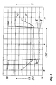
- den zeitlichen Verlauf der relativen Last einer Gasturbinenanlage mit sequentieller Verbrennung bei einem zeitlich begrenzten Teillastbetrieb bei herkömmlicher Fahrweise (durchgezogene Kurve A) und nach der Erfindung (strichpunktierte Kurve B); und
- Fig. 3
- den zeitlichen Verlauf verschiedener Betriebsgrössen in einem Kombikraftwerk bei einem zeitlich begrenzten Teillastbetrieb nach der Erfindung.
- Fig. 1
- a highly simplified system diagram of a combined cycle power plant with a gas turbine plant with sequential combustion, as it is suitable for the method according to the invention;
- Fig. 2
- the time course of the relative load of a gas turbine plant with sequential combustion at a time-limited part-load operation in conventional driving (solid curve A) and according to the invention (dashed curve B); and
- Fig. 3
- the time course of various operating variables in a combined cycle power plant at a time-limited partial load operation according to the invention.
In
Das Kombikraftwerk der
Der Verdichter 12 saugt Verbrennungsluft über den Lufteinlass 17 an und verdichtet sie. Die verdichtete Luft wird in die erste Brennkammer 15 eingeführt und dort zur Verbrennung eines über die erste Brennstoffzufuhr 18 eingedüsten ersten Brennstoffs herangezogen. Die heissen Verbrennungsgase, die noch einen Anteil an Sauerstoff enthalten, werden in der ersten (Hochdruck-)Turbine 13 unter Arbeitsleistung entspannt und anschliessend in die zweite Brennkammer 16 geleitet, wo der Sauerstoff zur Verbrennung eines durch die zweite Brennstoffzufuhr 19 zugeführten zweiten Brennstoffs eingesetzt wird. Die heissen Gase aus der zweiten Brennkammer 16 kommen in der zweiten Turbine 14 unter Arbeitsleistung zur Entspannung und anschliessend über eine Zuleitung 20 an den Abhitzedampferzeuger 22 abgegeben, der in den Wasser/Dampf-Kreislauf 25 eingeschaltet ist und Dampf für eine Dampfturbine 23 erzeugt. Die Dampfturbine 23 treibt in diesem Beispiel einen weiteren Generator 24 an, kann aber auch mit dem Generator 11 gekoppelt sein. Weitere Elemente des Wasser/Dampf-Kreislaufs wie Kondensator, Speisewasserkessel, Speisewasserpumpe etc. sind der Einfachheit halber in
In einer beispielhaften Anlage gemäss
Eine vereinfachte Darstellung des zeitlichen Verhaltens verschiedener Parameter bei einem solchen intermediären Absenken des Betriebs der Kombianlage auf eine sehr niedrige Teillast ist in
Insgesamt hat die erfindungsgemässe Betriebsweise (Absenkung der Teillast mit Abschalten der sequentiellen Verbrennung) die folgenden Charakteristika und Vorteile:
- Es werden Start-Stop-Zyklen und damit die zyklische thermische Belastung der entsprechenden Anlagenteile vermieden.
- Die Wartungskosten und Wartungsintervalle werden nicht negativ beeinflusst.
- Es wird dadurch ein ausreichender Wirkungsgrad der Anlage und gleichzeitig ein niedriger Brennstoffverbrauch ermöglicht.
- Es können im niedrigen Teillastbetrieb niedrige Emissionswerte erreicht werden, die nahe an denen bei Grundlast liegen, oder sogar entsprechend sind.
- Es wird eine (drehende) Betriebsreserve bereitgestellt, die bei Bedarf schnell und einfach abrufbar ist. Die normale Hochfahrfähigkeit des Kombikraftwerks bleibt dabei weitgehend erhalten.
- Die Fahrweise erlaubt ein schnelles Hochfahren der Last, um hohe Preisspannen zwischen Brennstoffpreis und kWh-Preis (sog. "spark spreads") auszunutzen, wenn sie auftreten, da keine mit einem Anfahren verbundenen Verzögerungen durch Anlagenvorbereitung, Anfahren der Gasturbine, Spülen des Abhitzedampferzeugers, Anwärmen des Wasser/Dampf-Kreislaufs etc., entstehen.
- Es wird das potentielle Risiko eines Fehlstarts vermieden, da die Anlage in Betrieb bleibt.
- Es wird die Emission von zusätzlichem Lärm und Wasserdampffahnen vermieden, die während einer Startphase auftreten können.
- Gegenüber dem bisherigen "Parken" der Anlage bei höheren Teillasten (z.B. 40%) werden die Emissionen insgesamt erheblich reduziert.
- Es wird eine homogene Verteilung der Turbineneinlasstemperatur in der Gasturbine sichergestellt, was bei Maschinen ohne sequentielle Verbrennung wegen des dort notwendigen Pilotbetriebes oder stufenweisen Betriebes (mit verschiedenen Brennergruppen) nicht möglich ist.
- Start-stop cycles and thus the cyclic thermal load of the corresponding system parts are avoided.
- The maintenance costs and maintenance intervals are not negatively affected.
- It is thereby a sufficient efficiency of the system and at the same time allows low fuel consumption.
- Low emissions can be achieved at low part-load conditions that are close to or even equivalent to base load.
- It provides a (rotating) operating reserve, which is quickly and easily retrievable when needed. The normal power-up capability of the combined cycle power plant remains largely intact.
- The driving style allows a fast start-up of the load to exploit high price margins between fuel price and kWh price (so-called "spark spreads"), if they occur, since there are no delays due to start-up, preparation of the gas turbine, flushing of the heat recovery steam generator, Warming up the water / steam circuit, etc., arise.
- It avoids the potential risk of a false start because the system remains in operation.
- It avoids the emission of additional noise and plumes that may occur during a launch phase.
- Compared with the previous "parking" of the system at higher partial loads (eg 40%), emissions are significantly reduced overall.
- It is ensured a homogeneous distribution of the turbine inlet temperature in the gas turbine, which is not possible in machines without sequential combustion because of the necessary there pilot operation or stepwise operation (with different burner groups).
- 1010
- Gasturbinenanlage (mit sequentieller Verbrennung)Gas turbine plant (with sequential combustion)
- 11,2411.24
- Generatorgenerator
- 1212
- Verdichtercompressor
- 13,1413.14
- Turbineturbine
- 15,1615,16
- Brennkammercombustion chamber
- 1717
- Lufteinlassair intake
- 18,1918.19
- Brennstoffzufuhrfuel supply
- 2020
- Abgasauslassexhaust outlet
- 2121
- Wellewave
- 2222
- Abhitzedampferzeugerheat recovery steam generator
- 2323
- Dampfturbinesteam turbine
- 2525
- Wasser/Dampf-KreislaufWater / steam cycle
- A,..,GA, .., G
- KurveCurve
- RTRT
- relative Lastrelative load
- t1t1
- ZeitraumPeriod
Claims (3)
- Method for operating a gas turbine plant (10) essentially consisting of at least one compressor (12) for the compression of sucked-in combustion air, of a first combustion chamber (15), acting downstream of the compressor, for the combustion of a first fuel by means of the compressed combustion air, of a first turbine (13), acting downstream of the first combustion chamber (15), of a second combustion chamber (16), acting downstream of the first turbine, for the combustion of a second fuel by means of the gases emerging from the first turbine (13), and of a second turbine (14) following the second combustion chamber (16) downstream, the second combustion chamber (16) being cut off completely in order to achieve low part-load operation of the gas turbine plant (10), characterized in that, during the time (t1) in which the second combustion chamber (16) is cut off, the first combustion chamber (15) is operated in a lean premixing mode, in such a way that a multiplicity of individual burners are arranged, distributed, in the first combustion chamber (15), and in that, during the time (t1) in which the second combustion chamber (16) is cut off, all the burners of the first combustion chamber (15) are operated.
- Method according to Claim 1, characterized in that the gas turbine plant (10) is operated, in low part-load operation, with a relative load (RL) of less than 20%.
- Method according to either one of Claims 1 and 2, characterized in that the gas turbine plant (10) is part of a combined-cycle power station (10, 25) with a water/steam circuit (25), with a steam turbine (23) and with a waste-heat recovery steam generator (22) through which the exhaust gases from the gas turbine plant (10) flow, and in that the combined-cycle power station (10, 25) is operated, in low part-load operation, overall with a relative load (RL) of less than 25%.
Applications Claiming Priority (1)
| Application Number | Priority Date | Filing Date | Title |
|---|---|---|---|
| CH16492006 | 2006-10-16 |
Publications (3)
| Publication Number | Publication Date |
|---|---|
| EP1914407A2 EP1914407A2 (en) | 2008-04-23 |
| EP1914407A3 EP1914407A3 (en) | 2009-12-23 |
| EP1914407B1 true EP1914407B1 (en) | 2012-01-04 |
Family
ID=37758757
Family Applications (1)
| Application Number | Title | Priority Date | Filing Date |
|---|---|---|---|
| EP07115606A Not-in-force EP1914407B1 (en) | 2006-10-16 | 2007-09-04 | Method for operating a gas turbine plant |
Country Status (3)
| Country | Link |
|---|---|
| US (1) | US7950239B2 (en) |
| EP (1) | EP1914407B1 (en) |
| AT (1) | ATE540213T1 (en) |
Families Citing this family (15)
| Publication number | Priority date | Publication date | Assignee | Title |
|---|---|---|---|---|
| US8220269B2 (en) * | 2008-09-30 | 2012-07-17 | Alstom Technology Ltd. | Combustor for a gas turbine engine with effusion cooled baffle |
| US8220271B2 (en) * | 2008-09-30 | 2012-07-17 | Alstom Technology Ltd. | Fuel lance for a gas turbine engine including outer helical grooves |
| US8164208B2 (en) * | 2009-04-15 | 2012-04-24 | General Electric Company | Systems involving multi-spool generators and variable speed electrical generators |
| CN103154445B (en) | 2010-10-19 | 2015-06-17 | 阿尔斯通技术有限公司 | Method for operating combined-cycle power plant with cogeneration and combined-cycle power plant for carrying out the method |
| RU2563447C2 (en) | 2010-10-19 | 2015-09-20 | Альстом Текнолоджи Лтд | Method of operation of combined cycle power plant with cogeneration and combined cycle power plant for realisation of this method |
| ITMI20111576A1 (en) * | 2011-09-02 | 2013-03-03 | Alstom Technology Ltd | METHOD TO SWITCH A COMBUSTION DEVICE |
| US9353682B2 (en) | 2012-04-12 | 2016-05-31 | General Electric Company | Methods, systems and apparatus relating to combustion turbine power plants with exhaust gas recirculation |
| US8539749B1 (en) | 2012-04-12 | 2013-09-24 | General Electric Company | Systems and apparatus relating to reheat combustion turbine engines with exhaust gas recirculation |
| US20130269358A1 (en) * | 2012-04-12 | 2013-10-17 | General Electric Company | Methods, systems and apparatus relating to reheat combustion turbine engines with exhaust gas recirculation |
| EP2722492A1 (en) * | 2012-10-22 | 2014-04-23 | Alstom Technology Ltd | Method for operating a gas turbine with sequential combustion |
| AU2017356668B2 (en) | 2016-11-09 | 2023-04-20 | 8 Rivers Capital, Llc | Systems and methods for power production with integrated production of hydrogen |
| EP3421761B1 (en) * | 2017-06-30 | 2020-11-25 | Ansaldo Energia IP UK Limited | Second-stage combustor for a sequential combustor of a gas turbine |
| CN114538376B (en) | 2017-11-09 | 2024-07-30 | 八河流资产有限责任公司 | System and method for producing and separating hydrogen and carbon dioxide |
| AU2020292848A1 (en) | 2019-06-13 | 2022-02-03 | 8 Rivers Capital, Llc | Power production with cogeneration of further products |
| EP4433414A1 (en) | 2021-11-18 | 2024-09-25 | 8 Rivers Capital, LLC | Apparatus for hydrogen production |
Family Cites Families (10)
| Publication number | Priority date | Publication date | Assignee | Title |
|---|---|---|---|---|
| US3054257A (en) * | 1953-03-10 | 1962-09-18 | Garrett Corp | Gas turbine power plant for vehicles |
| DE2648628A1 (en) * | 1976-10-27 | 1978-05-03 | Motoren Turbinen Union | Multi-shaft turbojet propulsion unit - has extra combustion chamber between high and low pressure turbines operated when at full speed and entry temp. |
| DE4118062A1 (en) * | 1991-06-01 | 1992-12-03 | Asea Brown Boveri | COMBINED GAS / VAPOR POWER PLANT |
| CH687269A5 (en) | 1993-04-08 | 1996-10-31 | Abb Management Ag | Gas turbine group. |
| DE59309644D1 (en) | 1993-09-06 | 1999-07-15 | Asea Brown Boveri | Process for creating a partial load operation for a gas turbine group |
| EP0646704B1 (en) * | 1993-09-06 | 1997-11-26 | Asea Brown Boveri Ag | Method for controlling a gas turbine plan equipped with two combustion chambers |
| DE4446610A1 (en) | 1994-12-24 | 1996-06-27 | Abb Management Ag | Process for operating a gas turbine group |
| DE19508018A1 (en) * | 1995-03-07 | 1996-09-12 | Abb Management Ag | Process for operating a power plant |
| DE59711519D1 (en) * | 1997-12-17 | 2004-05-19 | Alstom Technology Ltd Baden | Process for operating a gas turbine group |
| DE10360951A1 (en) * | 2003-12-23 | 2005-07-28 | Alstom Technology Ltd | Thermal power plant with sequential combustion and reduced CO2 emissions and method of operating such a plant |
-
2007
- 2007-09-04 AT AT07115606T patent/ATE540213T1/en active
- 2007-09-04 EP EP07115606A patent/EP1914407B1/en not_active Not-in-force
- 2007-10-08 US US11/868,810 patent/US7950239B2/en not_active Expired - Fee Related
Also Published As
| Publication number | Publication date |
|---|---|
| ATE540213T1 (en) | 2012-01-15 |
| US7950239B2 (en) | 2011-05-31 |
| US20080087001A1 (en) | 2008-04-17 |
| EP1914407A3 (en) | 2009-12-23 |
| EP1914407A2 (en) | 2008-04-23 |
Similar Documents
| Publication | Publication Date | Title |
|---|---|---|
| EP1914407B1 (en) | Method for operating a gas turbine plant | |
| EP2473726B1 (en) | Gas turbine group | |
| EP0795685B1 (en) | Multi-staged gas-turbine with steam cooling and feeding into the combustor | |
| EP0851104B1 (en) | Gas turbine with heat recovery steam generator for cooling the combustion chamber, then injecting downstream of the combustion zone | |
| CH699804A1 (en) | Gas turbine plant with exhaust gas recirculation and method for operating such a plant. | |
| DE102009003406A1 (en) | Method and system for supporting a modification of a combined cycle working fluid and its combustion | |
| EP2627883A1 (en) | Method for operating a gas turbine in the case of load shedding, a device for controlling the operation of a gas turbine and a power plant | |
| DE102009043864A1 (en) | Channel burner for low calorific fuel for heating systems and heat recovery systems | |
| WO2007141101A1 (en) | Method of operating a gas turbine, application of the method in a combined cycle power plant, and combined cycle power plant for carrying out the method | |
| EP2071157A1 (en) | Method for controlling a gas turbine in a power plant and power plant for carrying out the method | |
| EP0768449A1 (en) | Process for operating a power plant | |
| DE10307374A1 (en) | Process for operating a partially closed, supercharged gas turbine cycle and gas turbine system for carrying out the process | |
| WO2008065156A1 (en) | Method for operating a gas turbine | |
| DE112010003300T5 (en) | Gas turbine and method for operating a gas turbine | |
| EP1866521A2 (en) | Method for starting a gas and steam turbine system | |
| DE1476806A1 (en) | Method and device for standby idling operation of a gas turbine generator which is connected to an electrical power supply network | |
| CH698412B1 (en) | Power plant turbine system. | |
| EP2614236A1 (en) | Electric power station | |
| CH701017A2 (en) | System and method for heating fuel for a gas turbine. | |
| EP0758045B1 (en) | Starting process for a single shaft combined power plant | |
| CH708180B1 (en) | Gas turbine engine with two combustion chambers and one bypass duct. | |
| EP1790834A1 (en) | Turbosatz mit Vorrichtung zum Hochfahren | |
| WO2008107406A2 (en) | Combined power plant and method for starting up a combined power plant | |
| CH706939A2 (en) | Power Augmentation Systems and frequency control. | |
| EP2876280A1 (en) | Micro gas turbine assembly |
Legal Events
| Date | Code | Title | Description |
|---|---|---|---|
| PUAI | Public reference made under article 153(3) epc to a published international application that has entered the european phase |
Free format text: ORIGINAL CODE: 0009012 |
|
| AK | Designated contracting states |
Kind code of ref document: A2 Designated state(s): AT BE BG CH CY CZ DE DK EE ES FI FR GB GR HU IE IS IT LI LT LU LV MC MT NL PL PT RO SE SI SK TR |
|
| AX | Request for extension of the european patent |
Extension state: AL BA HR MK RS |
|
| PUAL | Search report despatched |
Free format text: ORIGINAL CODE: 0009013 |
|
| AK | Designated contracting states |
Kind code of ref document: A3 Designated state(s): AT BE BG CH CY CZ DE DK EE ES FI FR GB GR HU IE IS IT LI LT LU LV MC MT NL PL PT RO SE SI SK TR |
|
| AX | Request for extension of the european patent |
Extension state: AL BA HR MK RS |
|
| RIC1 | Information provided on ipc code assigned before grant |
Ipc: F02C 6/00 20060101AFI20071218BHEP |
|
| 17P | Request for examination filed |
Effective date: 20100607 |
|
| 17Q | First examination report despatched |
Effective date: 20100728 |
|
| AKX | Designation fees paid |
Designated state(s): AT BE BG CH CY CZ DE DK EE ES FI FR GB GR HU IE IS IT LI LT LU LV MC MT NL PL PT RO SE SI SK TR |
|
| GRAP | Despatch of communication of intention to grant a patent |
Free format text: ORIGINAL CODE: EPIDOSNIGR1 |
|
| RIC1 | Information provided on ipc code assigned before grant |
Ipc: F02C 6/00 20060101AFI20110621BHEP |
|
| GRAS | Grant fee paid |
Free format text: ORIGINAL CODE: EPIDOSNIGR3 |
|
| GRAA | (expected) grant |
Free format text: ORIGINAL CODE: 0009210 |
|
| AK | Designated contracting states |
Kind code of ref document: B1 Designated state(s): AT BE BG CH CY CZ DE DK EE ES FI FR GB GR HU IE IS IT LI LT LU LV MC MT NL PL PT RO SE SI SK TR |
|
| REG | Reference to a national code |
Ref country code: GB Ref legal event code: FG4D Free format text: NOT ENGLISH |
|
| REG | Reference to a national code |
Ref country code: CH Ref legal event code: EP |
|
| REG | Reference to a national code |
Ref country code: AT Ref legal event code: REF Ref document number: 540213 Country of ref document: AT Kind code of ref document: T Effective date: 20120115 |
|
| REG | Reference to a national code |
Ref country code: IE Ref legal event code: FG4D |
|
| REG | Reference to a national code |
Ref country code: DE Ref legal event code: R096 Ref document number: 502007008992 Country of ref document: DE Effective date: 20120301 |
|
| REG | Reference to a national code |
Ref country code: NL Ref legal event code: VDEP Effective date: 20120104 |
|
| PG25 | Lapsed in a contracting state [announced via postgrant information from national office to epo] |
Ref country code: SI Free format text: LAPSE BECAUSE OF FAILURE TO SUBMIT A TRANSLATION OF THE DESCRIPTION OR TO PAY THE FEE WITHIN THE PRESCRIBED TIME-LIMIT Effective date: 20120104 |
|
| LTIE | Lt: invalidation of european patent or patent extension |
Effective date: 20120104 |
|
| PG25 | Lapsed in a contracting state [announced via postgrant information from national office to epo] |
Ref country code: BG Free format text: LAPSE BECAUSE OF FAILURE TO SUBMIT A TRANSLATION OF THE DESCRIPTION OR TO PAY THE FEE WITHIN THE PRESCRIBED TIME-LIMIT Effective date: 20120404 Ref country code: IS Free format text: LAPSE BECAUSE OF FAILURE TO SUBMIT A TRANSLATION OF THE DESCRIPTION OR TO PAY THE FEE WITHIN THE PRESCRIBED TIME-LIMIT Effective date: 20120504 Ref country code: NL Free format text: LAPSE BECAUSE OF FAILURE TO SUBMIT A TRANSLATION OF THE DESCRIPTION OR TO PAY THE FEE WITHIN THE PRESCRIBED TIME-LIMIT Effective date: 20120104 Ref country code: LT Free format text: LAPSE BECAUSE OF FAILURE TO SUBMIT A TRANSLATION OF THE DESCRIPTION OR TO PAY THE FEE WITHIN THE PRESCRIBED TIME-LIMIT Effective date: 20120104 |
|
| REG | Reference to a national code |
Ref country code: IE Ref legal event code: FD4D |
|
| PG25 | Lapsed in a contracting state [announced via postgrant information from national office to epo] |
Ref country code: GR Free format text: LAPSE BECAUSE OF FAILURE TO SUBMIT A TRANSLATION OF THE DESCRIPTION OR TO PAY THE FEE WITHIN THE PRESCRIBED TIME-LIMIT Effective date: 20120405 Ref country code: PL Free format text: LAPSE BECAUSE OF FAILURE TO SUBMIT A TRANSLATION OF THE DESCRIPTION OR TO PAY THE FEE WITHIN THE PRESCRIBED TIME-LIMIT Effective date: 20120104 Ref country code: PT Free format text: LAPSE BECAUSE OF FAILURE TO SUBMIT A TRANSLATION OF THE DESCRIPTION OR TO PAY THE FEE WITHIN THE PRESCRIBED TIME-LIMIT Effective date: 20120504 Ref country code: FI Free format text: LAPSE BECAUSE OF FAILURE TO SUBMIT A TRANSLATION OF THE DESCRIPTION OR TO PAY THE FEE WITHIN THE PRESCRIBED TIME-LIMIT Effective date: 20120104 Ref country code: LV Free format text: LAPSE BECAUSE OF FAILURE TO SUBMIT A TRANSLATION OF THE DESCRIPTION OR TO PAY THE FEE WITHIN THE PRESCRIBED TIME-LIMIT Effective date: 20120104 |
|
| PG25 | Lapsed in a contracting state [announced via postgrant information from national office to epo] |
Ref country code: CY Free format text: LAPSE BECAUSE OF FAILURE TO SUBMIT A TRANSLATION OF THE DESCRIPTION OR TO PAY THE FEE WITHIN THE PRESCRIBED TIME-LIMIT Effective date: 20120104 |
|
| PG25 | Lapsed in a contracting state [announced via postgrant information from national office to epo] |
Ref country code: RO Free format text: LAPSE BECAUSE OF FAILURE TO SUBMIT A TRANSLATION OF THE DESCRIPTION OR TO PAY THE FEE WITHIN THE PRESCRIBED TIME-LIMIT Effective date: 20120104 Ref country code: DK Free format text: LAPSE BECAUSE OF FAILURE TO SUBMIT A TRANSLATION OF THE DESCRIPTION OR TO PAY THE FEE WITHIN THE PRESCRIBED TIME-LIMIT Effective date: 20120104 Ref country code: CZ Free format text: LAPSE BECAUSE OF FAILURE TO SUBMIT A TRANSLATION OF THE DESCRIPTION OR TO PAY THE FEE WITHIN THE PRESCRIBED TIME-LIMIT Effective date: 20120104 Ref country code: IE Free format text: LAPSE BECAUSE OF FAILURE TO SUBMIT A TRANSLATION OF THE DESCRIPTION OR TO PAY THE FEE WITHIN THE PRESCRIBED TIME-LIMIT Effective date: 20120104 Ref country code: EE Free format text: LAPSE BECAUSE OF FAILURE TO SUBMIT A TRANSLATION OF THE DESCRIPTION OR TO PAY THE FEE WITHIN THE PRESCRIBED TIME-LIMIT Effective date: 20120104 Ref country code: SE Free format text: LAPSE BECAUSE OF FAILURE TO SUBMIT A TRANSLATION OF THE DESCRIPTION OR TO PAY THE FEE WITHIN THE PRESCRIBED TIME-LIMIT Effective date: 20120104 |
|
| PLBE | No opposition filed within time limit |
Free format text: ORIGINAL CODE: 0009261 |
|
| STAA | Information on the status of an ep patent application or granted ep patent |
Free format text: STATUS: NO OPPOSITION FILED WITHIN TIME LIMIT |
|
| PG25 | Lapsed in a contracting state [announced via postgrant information from national office to epo] |
Ref country code: SK Free format text: LAPSE BECAUSE OF FAILURE TO SUBMIT A TRANSLATION OF THE DESCRIPTION OR TO PAY THE FEE WITHIN THE PRESCRIBED TIME-LIMIT Effective date: 20120104 Ref country code: IT Free format text: LAPSE BECAUSE OF FAILURE TO SUBMIT A TRANSLATION OF THE DESCRIPTION OR TO PAY THE FEE WITHIN THE PRESCRIBED TIME-LIMIT Effective date: 20120104 |
|
| 26N | No opposition filed |
Effective date: 20121005 |
|
| REG | Reference to a national code |
Ref country code: DE Ref legal event code: R097 Ref document number: 502007008992 Country of ref document: DE Effective date: 20121005 |
|
| BERE | Be: lapsed |
Owner name: ALSTOM TECHNOLOGY LTD Effective date: 20120930 |
|
| PG25 | Lapsed in a contracting state [announced via postgrant information from national office to epo] |
Ref country code: MC Free format text: LAPSE BECAUSE OF NON-PAYMENT OF DUE FEES Effective date: 20120930 Ref country code: ES Free format text: LAPSE BECAUSE OF FAILURE TO SUBMIT A TRANSLATION OF THE DESCRIPTION OR TO PAY THE FEE WITHIN THE PRESCRIBED TIME-LIMIT Effective date: 20120415 |
|
| REG | Reference to a national code |
Ref country code: CH Ref legal event code: PL |
|
| REG | Reference to a national code |
Ref country code: FR Ref legal event code: ST Effective date: 20130531 |
|
| PG25 | Lapsed in a contracting state [announced via postgrant information from national office to epo] |
Ref country code: LI Free format text: LAPSE BECAUSE OF NON-PAYMENT OF DUE FEES Effective date: 20120930 Ref country code: CH Free format text: LAPSE BECAUSE OF NON-PAYMENT OF DUE FEES Effective date: 20120930 Ref country code: BE Free format text: LAPSE BECAUSE OF NON-PAYMENT OF DUE FEES Effective date: 20120930 |
|
| PG25 | Lapsed in a contracting state [announced via postgrant information from national office to epo] |
Ref country code: FR Free format text: LAPSE BECAUSE OF NON-PAYMENT OF DUE FEES Effective date: 20121001 |
|
| REG | Reference to a national code |
Ref country code: AT Ref legal event code: MM01 Ref document number: 540213 Country of ref document: AT Kind code of ref document: T Effective date: 20120904 |
|
| PG25 | Lapsed in a contracting state [announced via postgrant information from national office to epo] |
Ref country code: MT Free format text: LAPSE BECAUSE OF FAILURE TO SUBMIT A TRANSLATION OF THE DESCRIPTION OR TO PAY THE FEE WITHIN THE PRESCRIBED TIME-LIMIT Effective date: 20120104 |
|
| PG25 | Lapsed in a contracting state [announced via postgrant information from national office to epo] |
Ref country code: AT Free format text: LAPSE BECAUSE OF NON-PAYMENT OF DUE FEES Effective date: 20120904 |
|
| PG25 | Lapsed in a contracting state [announced via postgrant information from national office to epo] |
Ref country code: TR Free format text: LAPSE BECAUSE OF FAILURE TO SUBMIT A TRANSLATION OF THE DESCRIPTION OR TO PAY THE FEE WITHIN THE PRESCRIBED TIME-LIMIT Effective date: 20120104 |
|
| PG25 | Lapsed in a contracting state [announced via postgrant information from national office to epo] |
Ref country code: LU Free format text: LAPSE BECAUSE OF NON-PAYMENT OF DUE FEES Effective date: 20120904 |
|
| PG25 | Lapsed in a contracting state [announced via postgrant information from national office to epo] |
Ref country code: HU Free format text: LAPSE BECAUSE OF FAILURE TO SUBMIT A TRANSLATION OF THE DESCRIPTION OR TO PAY THE FEE WITHIN THE PRESCRIBED TIME-LIMIT Effective date: 20070904 |
|
| REG | Reference to a national code |
Ref country code: DE Ref legal event code: R081 Ref document number: 502007008992 Country of ref document: DE Owner name: GENERAL ELECTRIC TECHNOLOGY GMBH, CH Free format text: FORMER OWNER: ALSTOM TECHNOLOGY LTD., BADEN, CH Ref country code: DE Ref legal event code: R081 Ref document number: 502007008992 Country of ref document: DE Owner name: ANSALDO ENERGIA IP UK LIMITED, GB Free format text: FORMER OWNER: ALSTOM TECHNOLOGY LTD., BADEN, CH |
|
| REG | Reference to a national code |
Ref country code: DE Ref legal event code: R081 Ref document number: 502007008992 Country of ref document: DE Owner name: ANSALDO ENERGIA IP UK LIMITED, GB Free format text: FORMER OWNER: GENERAL ELECTRIC TECHNOLOGY GMBH, BADEN, CH |
|
| REG | Reference to a national code |
Ref country code: GB Ref legal event code: 732E Free format text: REGISTERED BETWEEN 20170824 AND 20170830 |
|
| PGFP | Annual fee paid to national office [announced via postgrant information from national office to epo] |
Ref country code: GB Payment date: 20170921 Year of fee payment: 11 Ref country code: DE Payment date: 20170928 Year of fee payment: 11 |
|
| REG | Reference to a national code |
Ref country code: DE Ref legal event code: R119 Ref document number: 502007008992 Country of ref document: DE |
|
| GBPC | Gb: european patent ceased through non-payment of renewal fee |
Effective date: 20180904 |
|
| PG25 | Lapsed in a contracting state [announced via postgrant information from national office to epo] |
Ref country code: DE Free format text: LAPSE BECAUSE OF NON-PAYMENT OF DUE FEES Effective date: 20190402 |
|
| PG25 | Lapsed in a contracting state [announced via postgrant information from national office to epo] |
Ref country code: GB Free format text: LAPSE BECAUSE OF NON-PAYMENT OF DUE FEES Effective date: 20180904 |