EP1994334B1 - Combustor and method of operating a combustor - Google Patents
Combustor and method of operating a combustor Download PDFInfo
- Publication number
- EP1994334B1 EP1994334B1 EP07704399A EP07704399A EP1994334B1 EP 1994334 B1 EP1994334 B1 EP 1994334B1 EP 07704399 A EP07704399 A EP 07704399A EP 07704399 A EP07704399 A EP 07704399A EP 1994334 B1 EP1994334 B1 EP 1994334B1
- Authority
- EP
- European Patent Office
- Prior art keywords
- openings
- air
- combustor
- row
- dome
- Prior art date
- Legal status (The legal status is an assumption and is not a legal conclusion. Google has not performed a legal analysis and makes no representation as to the accuracy of the status listed.)
- Expired - Fee Related
Links
- 238000000034 method Methods 0.000 title claims description 8
- 238000002485 combustion reaction Methods 0.000 claims description 30
- 230000007704 transition Effects 0.000 claims description 18
- 238000002347 injection Methods 0.000 claims description 13
- 239000007924 injection Substances 0.000 claims description 13
- 230000003247 decreasing effect Effects 0.000 claims description 2
- 239000000446 fuel Substances 0.000 description 38
- 239000007789 gas Substances 0.000 description 19
- 239000000203 mixture Substances 0.000 description 12
- 239000007788 liquid Substances 0.000 description 7
- 230000001419 dependent effect Effects 0.000 description 2
- 230000035515 penetration Effects 0.000 description 2
- 239000000047 product Substances 0.000 description 2
- 230000007423 decrease Effects 0.000 description 1
- 238000011161 development Methods 0.000 description 1
- 230000018109 developmental process Effects 0.000 description 1
- 235000015250 liver sausages Nutrition 0.000 description 1
- 230000002093 peripheral effect Effects 0.000 description 1
- 239000013589 supplement Substances 0.000 description 1
- 238000011144 upstream manufacturing Methods 0.000 description 1
Images

Classifications
-
- F—MECHANICAL ENGINEERING; LIGHTING; HEATING; WEAPONS; BLASTING
- F23—COMBUSTION APPARATUS; COMBUSTION PROCESSES
- F23R—GENERATING COMBUSTION PRODUCTS OF HIGH PRESSURE OR HIGH VELOCITY, e.g. GAS-TURBINE COMBUSTION CHAMBERS
- F23R3/00—Continuous combustion chambers using liquid or gaseous fuel
- F23R3/02—Continuous combustion chambers using liquid or gaseous fuel characterised by the air-flow or gas-flow configuration
- F23R3/04—Air inlet arrangements
- F23R3/06—Arrangement of apertures along the flame tube
-
- F—MECHANICAL ENGINEERING; LIGHTING; HEATING; WEAPONS; BLASTING
- F23—COMBUSTION APPARATUS; COMBUSTION PROCESSES
- F23C—METHODS OR APPARATUS FOR COMBUSTION USING FLUID FUEL OR SOLID FUEL SUSPENDED IN A CARRIER GAS OR AIR
- F23C7/00—Combustion apparatus characterised by arrangements for air supply
-
- F—MECHANICAL ENGINEERING; LIGHTING; HEATING; WEAPONS; BLASTING
- F23—COMBUSTION APPARATUS; COMBUSTION PROCESSES
- F23C—METHODS OR APPARATUS FOR COMBUSTION USING FLUID FUEL OR SOLID FUEL SUSPENDED IN A CARRIER GAS OR AIR
- F23C2202/00—Fluegas recirculation
- F23C2202/40—Inducing local whirls around flame
-
- F—MECHANICAL ENGINEERING; LIGHTING; HEATING; WEAPONS; BLASTING
- F23—COMBUSTION APPARATUS; COMBUSTION PROCESSES
- F23D—BURNERS
- F23D2206/00—Burners for specific applications
- F23D2206/10—Turbines
-
- F—MECHANICAL ENGINEERING; LIGHTING; HEATING; WEAPONS; BLASTING
- F23—COMBUSTION APPARATUS; COMBUSTION PROCESSES
- F23D—BURNERS
- F23D2900/00—Special features of, or arrangements for burners using fluid fuels or solid fuels suspended in a carrier gas
- F23D2900/00015—Pilot burners specially adapted for low load or transient conditions, e.g. for increasing stability
Definitions
- the present invention relates to a combustor comprising in flow series a burner, a transition piece and a combustion chamber being of larger diameter than the transition piece, the combustion chamber being connected to the transition piece via a dome portion.
- the invention relates to a method of operating a combustor, especially a combustor of a gas turbine.
- Modern gas turbine engines such as the one known from US 2004/0137395 A , use the concept of premixing air and fuel in lean stoichiometry before the combustion of the fuel/air mixture.
- the pre-mixing takes place by injecting fuel into an air stream in a swirling zone of a combustor which is located upstream from the combustion zone.
- the swirling leads to a mixing of fuel and air before the mixture enters the combustion zone.
- US 6,532,726 B2 describes a gas turbine engine system having a combustor with a burner head having injection arrangements for gas- and liquid-fuel operations. During both gas- and liquid-fuel operations the flame front face is located close to the burner head and, during liquid-fuel operations, air is forced across the downstream face to cool the head.
- the aerodynamics in the combustor dome comprise of a annular recirculation bubble that has a helical flow pattern in the circumferential sense. This recirculation bubble is driven by the swirling flow emerging from the pre-chamber.
- This recirculation bubble is driven by the swirling flow emerging from the pre-chamber.
- the central recirculation bubble has sufficient swirl and intensity for the flame front to be fully held.
- a combustor in particular a gas turbine combustor, and a method of operating a combustor, especially a gas turbine combustor which is advantageous in providing a combustion efficiency at low loads and starting.
- the inventive combustor comprises in flow series a burner, a transition piece and a combustion chamber being of larger diameter than the transition piece.
- the combustion chamber is connected to the transition piece via a dome portion. Air injection openings are located in the dome portion.
- the transition piece may also be referred to as a pre-chamber in regard to the combustion chamber.
- the openings comprise a first row of openings being positioned at a circle of a first radius of the dome portion and at least one further row of openings being positioned at at least one further circle of a second radius of the dome portion being different to the first radius.
- the openings have an elongated shape with a long direction and a short direction.
- the openings have a shape of an ellipse.
- the openings can be of any other shape.
- the openings of the first and the at least one further row can have a defined orientation e.g. such as the openings being positioned at an innermost circle of the dome portion are oriented tangentially with their elongated direction and the openings being positioned at the outermost circle of the dome portion have no tangential component in their elongated direction.
- the orientation of openings being arranged in further rows lying between the rows being positioned at the innermost and the outermost radius may be then dependent on the radius at which they are positioned.
- the tangential component proportion of an openings long direction increases as nearer the opening is positioned at the innermost radius of the dome portion and decreases as nearer the opening is positioned at the outermost radius of the dome portion.
- duct portions of ducts for feeding the air to the opening adjoining the air injection openings are designed so that they have angles of inclination to the surface normal of the dome surface greater than 45 degrees and less than 80 degrees.
- angled jets have angles of inclination to the surface front to which they emerge of less than 11 degrees (i.e. of more than 80 degrees relative to the surface normal) it will be difficult to attach them to the surface of the surface.
- an air jet streaming through an opening of a row being positioned at the outermost radius of the dome portion has no tangential component.
- Air jets flowing through openings of the other rows have tangential components that increase with decreasing radial position.
- the first row of openings is arranged close to a dome edge, where the dome portion is adjacent the transition piece.
- the number of openings of the first row may be greater than the number of openings of the at least one further row.
- the higher number of openings ensures a sufficient introduction of air near the transition piece due to provision of greater air penetration.
- the openings of the first row are advantageously each smaller than openings of the at least one further row. Due to the greater number and the smaller diameter of these openings, an even introduction of air to the partially premixed gases leaving the transition piece is achieved.
- the inventive combustor is particularly adapted to perform the inventive method.
- the inventive method of operating a combustor which comprises in flow series a burner, a transition piece and a combustion chamber being of larger diameter than the transition piece and being connected to it via a dome portion comprises the step of introducing air from the dome portion of the combustor.
- the air is introduced by an inclination angle to the surface normal of the dome surface greater than 45 degrees and less than 80 degrees.
- Figure 1 shows a combustor according to the invention.
- the combustor comprises in flow direction series a burner 10 with swirler portion 12 and a burner-head portion 11 attached to the swirler portion 12, a transition piece being referred as combustion pre-chamber 13 and a main combustion chamber 4.
- the main combustion chamber 4 has a diameter being larger than the diameter of the pre-chamber 13.
- the main combustion chamber 4 is connected to the pre-chamber 13 via a dome portion 30 comprising a dome plate 38.
- the transition piece 13 may be implemented as a one part continuation of the burner 10 towards the combustion chamber 4, as a one part continuation of the combustion chamber 4 towards the burner 10, or as a separate part between the burner 10 and the combustion chamber 4.
- the combustor is adapted to be operated with either liquid or gaseous fuel and comprises a gas-fuel injection system, a liquid-fuel injection system and an air injection system.
- the gas-fuel injection system comprises main gas-fuel openings 23 and a pilot gas system.
- the main gas-fuel openings 23 are located at an air-inlet region of a burner head face 16, i.e. of the swirler portion 12, i.e. adjacent a radially outer part of passages 14 which are defined between a number of vanes of the swirler portion 12 and are fed from connectors 24.
- the pilot gas system comprises in flowing direction of pilot gas a connector 18 at the burner head 11, an annular gallery 19, gas outlets 32, a lip 20 extending radially inwards towards the longitudinal axis 21 of the combustor, and a central part 22 being arranged on a burner head face 16.
- the liquid-fuel injection system comprises liquid-fuel pilot openings 25 and main liquid-fuel openings 27.
- the liquid-fuel pilot openings 25 can inject liquid fuel fed from connections 26 through appropriate ducts extending through the burner head 11 into the pre-chamber 13.
- the pilot openings 25 are positioned in the central part 22 of the burner head face 16 outside the outer circumference of the combustion flames front FF.
- the main liquid-fuel openings 27 are fed from fuel connectors 28 through appropriate passageways extendingthrough the burner head 11.
- the main liquid-fuel openings 27 are situated in the burner head face 16 at or near the air-exit region of the swirler 12, i.e., near a radially inner portion of the swirler passages 14.
- the air injection system comprises air ducts 36 leading to openings 40, 42, 44 in the dome plate 38.
- the exit parts of the ducts i.e. the parts adjoining the openings, are inclined with respect to the surface normal of the dome pate 38 by an inclination angle ⁇ .
- compressed air 15 is supplied to the burner 10 and streams through the swirler passages 14.
- the in streaming air mixes with fuel injected into the compressed air streams through the passages from injection openings located in a peripheral section of the burner head face 16.
- the mixture is ignited by an igniter unit 17. Once lit, the flame continuous to burn so that a further ignition is not required.
- the pilot gas supplied through the connector 18 at the burner head 11 streams through passages in the burner head 11 arriving at the annular gallery 19. From there the pilot gas is directed via the gas outlets 32 to the underside of a directing means in the form of the lip 20 extending radially inwards towards the longitudinal axis 21 of the combustor. The lip 20 deflects the pilot gas across the central portion 22.
- the pilot gas supply is reduced and the main gas-fuel supply is increased.
- the main gas-fuel exits the main gas-fuel openings 23.
- the main gas-fuel and the air mix together as they pass the swirler passages 14 on their way to a combustion flame within pre-chamber 13 and main-chamber 4.
- air jets 34 are supplied by the air openings 36 into main combustion chamber 4. Therein, they mix in dependence of engine load with either with the pilot gas, the fuel-air mixture and/or the combustion products of them so as to improve the dome recirculation efficiency by providing sufficient swirl and intensity for the flame front.
- the injected air jets 34 have an inclination angle ⁇ in relation to the surface normal of the dome surface being shown as dashed line.
- pilot liquid-fuel is injected from pilot openings 25 into the pre-chamber 13 in an axial direction which is at least approximately parallel to the central longitudinal axis 21, where it mixes with air 15 exiting the swirler passages 14.
- the obtained mixture of air and fuel is ignited by the igniter unit 17. And further mixtures of air and fuel are fed to the so obtained flame F.
- the air jets 34 are supplied by the air openings 36 into the main combustion chamber 4. Therein, they mix with the mixture which leaves the pre-chamber 13.
- This mixture can comprise the pilot fuel, the air-fuel mixture being introduced into the combustor and/or their combustion products. Due to the orientation of the exit parts of the ducts 36 the air jets 34 have an inclination angle ⁇ in relation to the surface normal of the dome surface being shown as dashed line to compliment the existing aerodynamics and enhance the stability, especially, when the gas turbine is operating in the low load regime.
- main liquid fuel is introduced from the main liquid-fuel openings 27 which are located on the burner face in the air exit region of the swirler passages 14 and inject main liquid fuel in a direction approximately perpendicular to the air stream flow 15.
- the supply of air jets 34 can either be continued or stopped.
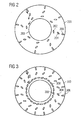
- Fig. 2 shows a dome portion according to the present invention.
- the dome portion comprises a plate 200 having a first row of openings 202, a second row of openings 204 and a third row of openings 206. All openings have an elongated shape defining a long direction of the openings.
- the openings 202 are positioned at the innermost radius of the plate 200 and closest to the dome edge 208. They are oriented near tangential to the dome edge 208 with their long direction.
- the openings 204 are arranged at radius being greater than the previous radius. Their orientation is less tangential than that of the openings 202 of the first row.
- the openings 206 are situated at the outermost radius and are oriented radially inwards with no tangential component of their long direction.
- openings 202, 204 and 206 air is introduced in the dome of the combustor.
- the air jets stream out the openings 202, 204 and 206 have an inclination in regard to a surface normal of a dome surface from which they emerge (see Fig. 1 ).
- the inclination angle ⁇ lies in the range of 45° ⁇ ⁇ ⁇ 80°.
- the jets streaming out openings 206 do not have a tangential component in regard to the dome edge 208, while the others have a tangential component.
- the flow direction of the air jets is shown by arrows.
- Fig. 3 shows another dome portion according to the present invention.
- the dome portion comprises a plate 300 having a first row of openings 302, a second row of openings 304 and a third row of openings 306.
- the openings 302 are positioned at the innermost radius of the plate 300 and closest to the dome edge 308 and are oriented near tangential to the dome edge 308.
- the openings 304 are arranged at radius being greater than the previous radius and are oriented less tangential than the openings 302.
- the openings 306 are situated at the outermost radius and are oriented radially inwards with no circumferential component.
- the number of openings 302 is greater as the number of openings 304 or the number of openings 306 Further, the diameters of the openings 302 are smaller than the diameters of the openings 304 or 306. Thereby, an even introduction of air to the fuel and/or gases being introduced in the dome portion of the combustor is ensured and a greater air penetration is provided.
- openings 302, 304 and 306 air is introduced in the dome of a combustion system.
- the air jets stream out the openings 302, 304 and 306 by an inclination angle ⁇ , wherein 45° ⁇ ⁇ ⁇ 80°, wherein ⁇ is defined in regard to a surface normal of a dome surface front from which the air jets emerge (see Fig. 1 ).
- the jets streaming out openings 306 do not have a tangential component in regard to the dome edge 308.
Description
- The present invention relates to a combustor comprising in flow series a burner, a transition piece and a combustion chamber being of larger diameter than the transition piece, the combustion chamber being connected to the transition piece via a dome portion. In addition, the invention relates to a method of operating a combustor, especially a combustor of a gas turbine.
- Modern gas turbine engines, such as the one known from
US 2004/0137395 A , use the concept of premixing air and fuel in lean stoichiometry before the combustion of the fuel/air mixture. Usually, the pre-mixing takes place by injecting fuel into an air stream in a swirling zone of a combustor which is located upstream from the combustion zone. The swirling leads to a mixing of fuel and air before the mixture enters the combustion zone. -
US 6,532,726 B2 describes a gas turbine engine system having a combustor with a burner head having injection arrangements for gas- and liquid-fuel operations. During both gas- and liquid-fuel operations the flame front face is located close to the burner head and, during liquid-fuel operations, air is forced across the downstream face to cool the head. - The aerodynamics in the combustor dome comprise of a annular recirculation bubble that has a helical flow pattern in the circumferential sense. This recirculation bubble is driven by the swirling flow emerging from the pre-chamber. Currently, it is known that at low machine loads the highest combustion efficiency can be achieved if the flame front is fully stabilised in the dome recirculation bubble. Poor efficiency is associated with a flame front stabilised in the central recirculation bubble, which is predominantly located in the pre-chamber area. At high machine loads, the central recirculation bubble has sufficient swirl and intensity for the flame front to be fully held.
- However, the combustion system has relatively poor combustion efficiency at low loads and at starting conditions. This problem exists for liquid and gas operation, although it is most noticeable on liquid.
- With respect to the mentioned state of the art it is an objective of the invention to provide a combustor, in particular a gas turbine combustor, and a method of operating a combustor, especially a gas turbine combustor which is advantageous in providing a combustion efficiency at low loads and starting.
- This objective is solved by a combustor according to claim 1 and a method according to claim 8. The dependent claims describe advantageous developments of the invention.
- The inventive combustor comprises in flow series a burner, a transition piece and a combustion chamber being of larger diameter than the transition piece. The combustion chamber is connected to the transition piece via a dome portion. Air injection openings are located in the dome portion. In particular, the transition piece may also be referred to as a pre-chamber in regard to the combustion chamber.
- It is believed that the state of the art dome recirculation bubble strength is only marginally insufficient and that limited additional air directed the appropriate way will improve the efficiency of the combustion system. To improve the dome recirculation efficiency where a machine would be operating predominantly in the low load regime, it is therefore proposed that air is introduced across the dome to supplement the existing aerodynamics and enhance stability.
- According to the present invention the openings comprise a first row of openings being positioned at a circle of a first radius of the dome portion and at least one further row of openings being positioned at at least one further circle of a second radius of the dome portion being different to the first radius. The openings have an elongated shape with a long direction and a short direction. Especially, the openings have a shape of an ellipse. However, the openings can be of any other shape.
- The openings of the first and the at least one further row can have a defined orientation e.g. such as the openings being positioned at an innermost circle of the dome portion are oriented tangentially with their elongated direction and the openings being positioned at the outermost circle of the dome portion have no tangential component in their elongated direction. The orientation of openings being arranged in further rows lying between the rows being positioned at the innermost and the outermost radius may be then dependent on the radius at which they are positioned. The tangential component proportion of an openings long direction increases as nearer the opening is positioned at the innermost radius of the dome portion and decreases as nearer the opening is positioned at the outermost radius of the dome portion. In addition duct portions of ducts for feeding the air to the opening adjoining the air injection openings are designed so that they have angles of inclination to the surface normal of the dome surface greater than 45 degrees and less than 80 degrees. When angled jets have angles of inclination to the surface front to which they emerge of less than 11 degrees (i.e. of more than 80 degrees relative to the surface normal) it will be difficult to attach them to the surface of the surface.
- With the described configuration of the openings, an air jet streaming through an opening of a row being positioned at the outermost radius of the dome portion has no tangential component. Air jets flowing through openings of the other rows have tangential components that increase with decreasing radial position.
- Advantageously, the first row of openings is arranged close to a dome edge, where the dome portion is adjacent the transition piece.
- The number of openings of the first row may be greater than the number of openings of the at least one further row. The higher number of openings ensures a sufficient introduction of air near the transition piece due to provision of greater air penetration.
- Further, the openings of the first row are advantageously each smaller than openings of the at least one further row. Due to the greater number and the smaller diameter of these openings, an even introduction of air to the partially premixed gases leaving the transition piece is achieved.
- The inventive combustor is particularly adapted to perform the inventive method.
- The inventive method of operating a combustor which comprises in flow series a burner, a transition piece and a combustion chamber being of larger diameter than the transition piece and being connected to it via a dome portion comprises the step of introducing air from the dome portion of the combustor.
- In an advantageous embodiment of the present invention, the air is introduced by an inclination angle to the surface normal of the dome surface greater than 45 degrees and less than 80 degrees.
- Further features, properties and advantages of the present invention will become clear from the following description of embodiments of the invention in conjunction with the accompanying drawings.
- Figure 1
- shows a combustor according to the invention;
- Figure 2
- shows a dome plate according to the present invention; and
- Figure 3
- shows another dome plate according to the present invention.
-
Figure 1 shows a combustor according to the invention. The combustor comprises in flow direction series aburner 10 withswirler portion 12 and a burner-head portion 11 attached to theswirler portion 12, a transition piece being referred as combustion pre-chamber 13 and a main combustion chamber 4. The main combustion chamber 4 has a diameter being larger than the diameter of the pre-chamber 13. The main combustion chamber 4 is connected to the pre-chamber 13 via adome portion 30 comprising adome plate 38. In general, thetransition piece 13 may be implemented as a one part continuation of theburner 10 towards the combustion chamber 4, as a one part continuation of the combustion chamber 4 towards theburner 10, or as a separate part between theburner 10 and the combustion chamber 4. - The combustor is adapted to be operated with either liquid or gaseous fuel and comprises a gas-fuel injection system, a liquid-fuel injection system and an air injection system.
- The gas-fuel injection system comprises main gas-
fuel openings 23 and a pilot gas system. The main gas-fuel openings 23 are located at an air-inlet region of aburner head face 16, i.e. of theswirler portion 12, i.e. adjacent a radially outer part ofpassages 14 which are defined between a number of vanes of theswirler portion 12 and are fed from connectors 24. The pilot gas system comprises in flowing direction of pilot gas aconnector 18 at theburner head 11, anannular gallery 19,gas outlets 32, alip 20 extending radially inwards towards thelongitudinal axis 21 of the combustor, and a central part 22 being arranged on aburner head face 16. - The liquid-fuel injection system comprises liquid-
fuel pilot openings 25 and main liquid-fuel openings 27. The liquid-fuel pilot openings 25 can inject liquid fuel fed fromconnections 26 through appropriate ducts extending through theburner head 11 into the pre-chamber 13. Thepilot openings 25 are positioned in the central part 22 of theburner head face 16 outside the outer circumference of the combustion flames front FF. The main liquid-fuel openings 27 are fed fromfuel connectors 28 through appropriate passageways extendingthrough theburner head 11. The main liquid-fuel openings 27 are situated in theburner head face 16 at or near the air-exit region of theswirler 12, i.e., near a radially inner portion of theswirler passages 14. - The air injection system comprises air ducts 36 leading to
openings dome plate 38. The exit parts of the ducts, i.e. the parts adjoining the openings, are inclined with respect to the surface normal of thedome pate 38 by an inclination angle α. - In operation,
compressed air 15 is supplied to theburner 10 and streams through theswirler passages 14. The in streaming air mixes with fuel injected into the compressed air streams through the passages from injection openings located in a peripheral section of theburner head face 16. On arriving in the pre-chamber 13, the mixture is ignited by an igniter unit 17. Once lit, the flame continuous to burn so that a further ignition is not required. - When the engine is started in gas-fuel mode of operation, the pilot gas supplied through the
connector 18 at theburner head 11 streams through passages in theburner head 11 arriving at theannular gallery 19. From there the pilot gas is directed via thegas outlets 32 to the underside of a directing means in the form of thelip 20 extending radially inwards towards thelongitudinal axis 21 of the combustor. Thelip 20 deflects the pilot gas across the central portion 22. However, as engine load and speed increase, the pilot gas supply is reduced and the main gas-fuel supply is increased. The main gas-fuel exits the main gas-fuel openings 23. The main gas-fuel and the air mix together as they pass theswirler passages 14 on their way to a combustion flame withinpre-chamber 13 and main-chamber 4. - Further, air jets 34 are supplied by the air openings 36 into main combustion chamber 4. Therein, they mix in dependence of engine load with either with the pilot gas, the fuel-air mixture and/or the combustion products of them so as to improve the dome recirculation efficiency by providing sufficient swirl and intensity for the flame front. The injected air jets 34 have an inclination angle α in relation to the surface normal of the dome surface being shown as dashed line.
- When the engine is started in the liquid-fuel mode of the combustor, pilot liquid-fuel is injected from
pilot openings 25 into the pre-chamber 13 in an axial direction which is at least approximately parallel to the centrallongitudinal axis 21, where it mixes withair 15 exiting theswirler passages 14. The obtained mixture of air and fuel is ignited by the igniter unit 17. And further mixtures of air and fuel are fed to the so obtained flame F. - Additionally, the air jets 34 are supplied by the air openings 36 into the main combustion chamber 4. Therein, they mix with the mixture which leaves the pre-chamber 13. This mixture can comprise the pilot fuel, the air-fuel mixture being introduced into the combustor and/or their combustion products. Due to the orientation of the exit parts of the ducts 36 the air jets 34 have an inclination angle α in relation to the surface normal of the dome surface being shown as dashed line to compliment the existing aerodynamics and enhance the stability, especially, when the gas turbine is operating in the low load regime.
- As engine load increases from start-up to approximately 70 % full load, the supply of liquid pilot fuel is reduced, and main liquid fuel is introduced from the main liquid-
fuel openings 27 which are located on the burner face in the air exit region of theswirler passages 14 and inject main liquid fuel in a direction approximately perpendicular to theair stream flow 15. The supply of air jets 34 can either be continued or stopped. -
Fig. 2 shows a dome portion according to the present invention. The dome portion comprises aplate 200 having a first row ofopenings 202, a second row ofopenings 204 and a third row ofopenings 206. All openings have an elongated shape defining a long direction of the openings. - The
openings 202 are positioned at the innermost radius of theplate 200 and closest to thedome edge 208. They are oriented near tangential to thedome edge 208 with their long direction. Theopenings 204 are arranged at radius being greater than the previous radius. Their orientation is less tangential than that of theopenings 202 of the first row. Theopenings 206 are situated at the outermost radius and are oriented radially inwards with no tangential component of their long direction. - Through
openings openings Fig. 1 ). The inclination angle α lies in the range of 45° < α < 80°. The jets streaming outopenings 206 do not have a tangential component in regard to thedome edge 208, while the others have a tangential component. The flow direction of the air jets is shown by arrows. -
Fig. 3 shows another dome portion according to the present invention. The dome portion comprises aplate 300 having a first row ofopenings 302, a second row ofopenings 304 and a third row ofopenings 306. - The
openings 302 are positioned at the innermost radius of theplate 300 and closest to thedome edge 308 and are oriented near tangential to thedome edge 308. Theopenings 304 are arranged at radius being greater than the previous radius and are oriented less tangential than theopenings 302. Theopenings 306 are situated at the outermost radius and are oriented radially inwards with no circumferential component. - The number of
openings 302 is greater as the number ofopenings 304 or the number ofopenings 306 Further, the diameters of theopenings 302 are smaller than the diameters of theopenings - Through
openings openings Fig. 1 ). The jets streaming outopenings 306 do not have a tangential component in regard to thedome edge 308.
Claims (7)
- A combustor for a gas turbine comprising in flow series a burner (10), a transition piece (13) and a combustion chamber (4) being of larger diameter than the transition piece (13), the combustion chamber (4) being connected to the transition piece (13) via a dome portion (30), and air injection openings (40, 42, 44, 202, 204, 206, 302, 304, 306) being located in the dome portion, the air injection openings (40, 42, 44, 202, 204, 206, 302, 304, 306) comprising a first row of openings being positioned on a circle of a first radius and at least one further row of openings being positioned on at least one further circle of a second radius being different to the first radius, wherein the openings (202, 204, 206, 302, 304, 306) have an enlarged shape with a long direction and a short direction, the long direction of the first row being oriented tangential or near tangential to the dome edge (208, 308) and wherein the tangential component portion of an opening's long direction increases as nearer the opening is positioned at the innermost radius of the dome portion.
- The combustor, as claimed in claim 1, wherein the first row of openings (202, 302) is arranged at a dome edge (208, 308) which is adjacent the transition piece (13).
- The combustor, as claimed in claim 1, wherein the number of openings (302) of the first row is greater than the number of openings (304, 306) of the at least one further row.
- The combustor, as claimed in claim 3, wherein the openings (302) of the first row have a diameter being smaller than a diameter of the openings (304, 306) of the at least one further row.
- The combustor, as claimed in claim 4, wherein duct portions of ducts (36) for feeding the air to the openings adjoining the air injection openings are designed such that they have angles of inclination (α) to the surface normal greater than 45 degrees and less than 80 degrees.
- A method of operating a combustor for a gas turbine according to claim 1, wherein air is introduced from the dome portion (30) by means of air jets, wherein an air jet without any tangential component streams through an opening of a row being positioned at the outermost radius of the dome portion and wherein air jets with tangential components that increase with decreasing radial position flow through openings of the other rows.
- The method, as claimed in claim 6, wherein the air is introduced with an inclination (α) to the surface normal of the dome portion (30) greater than 45 degrees and less than 80 degrees.
Priority Applications (1)
| Application Number | Priority Date | Filing Date | Title |
|---|---|---|---|
| EP07704399A EP1994334B1 (en) | 2006-03-13 | 2007-02-07 | Combustor and method of operating a combustor |
Applications Claiming Priority (3)
| Application Number | Priority Date | Filing Date | Title |
|---|---|---|---|
| EP06005106A EP1835229A1 (en) | 2006-03-13 | 2006-03-13 | Combustor and method of operating a combustor |
| PCT/EP2007/051141 WO2007104615A1 (en) | 2006-03-13 | 2007-02-07 | Combustor and method of operating a combustor |
| EP07704399A EP1994334B1 (en) | 2006-03-13 | 2007-02-07 | Combustor and method of operating a combustor |
Publications (2)
| Publication Number | Publication Date |
|---|---|
| EP1994334A1 EP1994334A1 (en) | 2008-11-26 |
| EP1994334B1 true EP1994334B1 (en) | 2010-03-31 |
Family
ID=36609522
Family Applications (2)
| Application Number | Title | Priority Date | Filing Date |
|---|---|---|---|
| EP06005106A Withdrawn EP1835229A1 (en) | 2006-03-13 | 2006-03-13 | Combustor and method of operating a combustor |
| EP07704399A Expired - Fee Related EP1994334B1 (en) | 2006-03-13 | 2007-02-07 | Combustor and method of operating a combustor |
Family Applications Before (1)
| Application Number | Title | Priority Date | Filing Date |
|---|---|---|---|
| EP06005106A Withdrawn EP1835229A1 (en) | 2006-03-13 | 2006-03-13 | Combustor and method of operating a combustor |
Country Status (4)
| Country | Link |
|---|---|
| US (1) | US20090117502A1 (en) |
| EP (2) | EP1835229A1 (en) |
| DE (1) | DE602007005620D1 (en) |
| WO (1) | WO2007104615A1 (en) |
Families Citing this family (1)
| Publication number | Priority date | Publication date | Assignee | Title |
|---|---|---|---|---|
| CA3010044C (en) | 2016-01-15 | 2021-06-15 | Siemens Aktiengesellschaft | Combustor for a gas turbine |
Family Cites Families (16)
| Publication number | Priority date | Publication date | Assignee | Title |
|---|---|---|---|---|
| US5055030A (en) * | 1982-03-04 | 1991-10-08 | Phillips Petroleum Company | Method for the recovery of hydrocarbons |
| EP0153842B1 (en) * | 1984-02-29 | 1988-07-27 | LUCAS INDUSTRIES public limited company | Combustion equipment |
| GB9023004D0 (en) * | 1990-10-23 | 1990-12-05 | Rolls Royce Plc | A gas turbine engine combustion chamber and a method of operating a gas turbine engine combustion chamber |
| US5307637A (en) * | 1992-07-09 | 1994-05-03 | General Electric Company | Angled multi-hole film cooled single wall combustor dome plate |
| JP3464487B2 (en) * | 1994-07-13 | 2003-11-10 | ボルボ エアロ コーポレイション | Low exhaust gas combustor for gas turbine engine |
| FR2751731B1 (en) * | 1996-07-25 | 1998-09-04 | Snecma | BOWL DEFLECTOR ASSEMBLY FOR A TURBOMACHINE COMBUSTION CHAMBER |
| GB2333832A (en) | 1998-01-31 | 1999-08-04 | Europ Gas Turbines Ltd | Multi-fuel gas turbine engine combustor |
| US6374615B1 (en) * | 2000-01-28 | 2002-04-23 | Alliedsignal, Inc | Low cost, low emissions natural gas combustor |
| US6427446B1 (en) * | 2000-09-19 | 2002-08-06 | Power Systems Mfg., Llc | Low NOx emission combustion liner with circumferentially angled film cooling holes |
| US6751961B2 (en) * | 2002-05-14 | 2004-06-22 | United Technologies Corporation | Bulkhead panel for use in a combustion chamber of a gas turbine engine |
| DE10233161B4 (en) * | 2002-07-22 | 2012-01-05 | Alstom Technology Ltd. | Burner and pilot burner |
| JP3940705B2 (en) * | 2003-06-19 | 2007-07-04 | 株式会社日立製作所 | Gas turbine combustor and fuel supply method thereof |
| US7260936B2 (en) * | 2004-08-27 | 2007-08-28 | Pratt & Whitney Canada Corp. | Combustor having means for directing air into the combustion chamber in a spiral pattern |
| US20060042257A1 (en) * | 2004-08-27 | 2006-03-02 | Pratt & Whitney Canada Corp. | Combustor heat shield and method of cooling |
| US7308794B2 (en) * | 2004-08-27 | 2007-12-18 | Pratt & Whitney Canada Corp. | Combustor and method of improving manufacturing accuracy thereof |
| EP1890083A1 (en) * | 2006-08-16 | 2008-02-20 | Siemens Aktiengesellschaft | Fuel injector for a gas turbine engine |
-
2006
- 2006-03-13 EP EP06005106A patent/EP1835229A1/en not_active Withdrawn
-
2007
- 2007-02-07 EP EP07704399A patent/EP1994334B1/en not_active Expired - Fee Related
- 2007-02-07 WO PCT/EP2007/051141 patent/WO2007104615A1/en active Application Filing
- 2007-02-07 US US12/224,903 patent/US20090117502A1/en not_active Abandoned
- 2007-02-07 DE DE602007005620T patent/DE602007005620D1/en active Active
Also Published As
| Publication number | Publication date |
|---|---|
| DE602007005620D1 (en) | 2010-05-12 |
| EP1835229A1 (en) | 2007-09-19 |
| US20090117502A1 (en) | 2009-05-07 |
| EP1994334A1 (en) | 2008-11-26 |
| WO2007104615A1 (en) | 2007-09-20 |
Similar Documents
| Publication | Publication Date | Title |
|---|---|---|
| US6363726B1 (en) | Mixer having multiple swirlers | |
| EP1193449B1 (en) | Multiple annular swirler | |
| EP1193448B1 (en) | Multiple annular combustion chamber swirler having atomizing pilot | |
| KR0149059B1 (en) | Gas turbine combustor including a diffusion nozzle assembly with a double cylindrical structure | |
| US6935116B2 (en) | Flamesheet combustor | |
| JP3628747B2 (en) | Nozzle for diffusion mode combustion and premixed mode combustion in a turbine combustor and method for operating a turbine combustor | |
| US9562690B2 (en) | Swirler, fuel and air assembly and combustor | |
| JP4162430B2 (en) | Method of operating gas turbine engine, combustor and mixer assembly | |
| US6826913B2 (en) | Airflow modulation technique for low emissions combustors | |
| JP5400936B2 (en) | Method and apparatus for burning fuel in a gas turbine engine | |
| EP2407720B1 (en) | Flame tolerant secondary fuel nozzle | |
| EP2481982B2 (en) | Mixer assembly for a gas turbine engine | |
| EP1952066B1 (en) | A combustion apparatus | |
| US8387393B2 (en) | Flashback resistant fuel injection system | |
| US20100263382A1 (en) | Dual orifice pilot fuel injector | |
| EP1795809A2 (en) | Gas turbine combustor | |
| US20090056336A1 (en) | Gas turbine premixer with radially staged flow passages and method for mixing air and gas in a gas turbine | |
| US20090111063A1 (en) | Lean premixed, radial inflow, multi-annular staged nozzle, can-annular, dual-fuel combustor | |
| US20120047897A1 (en) | Gas Turbine Combustor | |
| US20090320484A1 (en) | Methods and systems to facilitate reducing flashback/flame holding in combustion systems | |
| US20060096296A1 (en) | Method to decrease combustor emissions | |
| JP4086767B2 (en) | Method and apparatus for reducing combustor emissions | |
| EP1835231A1 (en) | Burner in particular for a gas turbine combustor, and method of operating a burner | |
| EP1243854B1 (en) | Fuel injector | |
| EP1994334B1 (en) | Combustor and method of operating a combustor |
Legal Events
| Date | Code | Title | Description |
|---|---|---|---|
| PUAI | Public reference made under article 153(3) epc to a published international application that has entered the european phase |
Free format text: ORIGINAL CODE: 0009012 |
|
| 17P | Request for examination filed |
Effective date: 20080728 |
|
| AK | Designated contracting states |
Kind code of ref document: A1 Designated state(s): DE FR GB IT |
|
| RBV | Designated contracting states (corrected) |
Designated state(s): DE FR GB IT |
|
| GRAP | Despatch of communication of intention to grant a patent |
Free format text: ORIGINAL CODE: EPIDOSNIGR1 |
|
| DAX | Request for extension of the european patent (deleted) | ||
| GRAS | Grant fee paid |
Free format text: ORIGINAL CODE: EPIDOSNIGR3 |
|
| GRAA | (expected) grant |
Free format text: ORIGINAL CODE: 0009210 |
|
| AK | Designated contracting states |
Kind code of ref document: B1 Designated state(s): DE FR GB IT |
|
| REG | Reference to a national code |
Ref country code: GB Ref legal event code: FG4D |
|
| REF | Corresponds to: |
Ref document number: 602007005620 Country of ref document: DE Date of ref document: 20100512 Kind code of ref document: P |
|
| PLBE | No opposition filed within time limit |
Free format text: ORIGINAL CODE: 0009261 |
|
| STAA | Information on the status of an ep patent application or granted ep patent |
Free format text: STATUS: NO OPPOSITION FILED WITHIN TIME LIMIT |
|
| 26N | No opposition filed |
Effective date: 20110104 |
|
| PGFP | Annual fee paid to national office [announced via postgrant information from national office to epo] |
Ref country code: IT Payment date: 20120222 Year of fee payment: 6 |
|
| PGFP | Annual fee paid to national office [announced via postgrant information from national office to epo] |
Ref country code: FR Payment date: 20130301 Year of fee payment: 7 Ref country code: GB Payment date: 20130213 Year of fee payment: 7 |
|
| PGFP | Annual fee paid to national office [announced via postgrant information from national office to epo] |
Ref country code: DE Payment date: 20130419 Year of fee payment: 7 |
|
| REG | Reference to a national code |
Ref country code: DE Ref legal event code: R119 Ref document number: 602007005620 Country of ref document: DE |
|
| GBPC | Gb: european patent ceased through non-payment of renewal fee |
Effective date: 20140207 |
|
| REG | Reference to a national code |
Ref country code: FR Ref legal event code: ST Effective date: 20141031 |
|
| REG | Reference to a national code |
Ref country code: DE Ref legal event code: R119 Ref document number: 602007005620 Country of ref document: DE Effective date: 20140902 |
|
| PG25 | Lapsed in a contracting state [announced via postgrant information from national office to epo] |
Ref country code: FR Free format text: LAPSE BECAUSE OF NON-PAYMENT OF DUE FEES Effective date: 20140228 Ref country code: GB Free format text: LAPSE BECAUSE OF NON-PAYMENT OF DUE FEES Effective date: 20140207 Ref country code: DE Free format text: LAPSE BECAUSE OF NON-PAYMENT OF DUE FEES Effective date: 20140902 |
|
| PG25 | Lapsed in a contracting state [announced via postgrant information from national office to epo] |
Ref country code: IT Free format text: LAPSE BECAUSE OF NON-PAYMENT OF DUE FEES Effective date: 20140207 |