EP2169109A1 - Klappbares Bügelbrett mit Schnellverschluss für Leitungen - Google Patents
Klappbares Bügelbrett mit Schnellverschluss für Leitungen Download PDFInfo
- Publication number
- EP2169109A1 EP2169109A1 EP09401018A EP09401018A EP2169109A1 EP 2169109 A1 EP2169109 A1 EP 2169109A1 EP 09401018 A EP09401018 A EP 09401018A EP 09401018 A EP09401018 A EP 09401018A EP 2169109 A1 EP2169109 A1 EP 2169109A1
- Authority
- EP
- European Patent Office
- Prior art keywords
- ironing board
- support structure
- fixed
- folding
- board according
- Prior art date
- Legal status (The legal status is an assumption and is not a legal conclusion. Google has not performed a legal analysis and makes no representation as to the accuracy of the status listed.)
- Granted
Links
Images

Classifications
-
- D—TEXTILES; PAPER
- D06—TREATMENT OF TEXTILES OR THE LIKE; LAUNDERING; FLEXIBLE MATERIALS NOT OTHERWISE PROVIDED FOR
- D06F—LAUNDERING, DRYING, IRONING, PRESSING OR FOLDING TEXTILE ARTICLES
- D06F81/00—Ironing boards
- D06F81/06—Ironing boards attachable to independent supports, e.g. walls
Definitions
- the invention relates to an ironing board with a support structure for at least one swiveling ironing board with Verrastungssystem and quick connectors for the connection of electrical lines and steam lines between ironing board and support structure.
- the ironing board is aligned horizontally and is supported by legs or support structures of various construction which rest on the ground and are not firmly connected thereto.
- ironing boards with a vertical support structure, which stands on the ground and at the side of a folding ironing board is attached.
- ironing boards that are either wall mounted or built into a piece of furniture and have a hinged ironing board attached to the fixed support structure.
- the ironing tables are hinged to the respective support structure - free-standing or permanently installed - and can be brought from the horizontal working position into the closed state, in which the ironing board is practically parallel to the support structure or the wall. In this way, the ironing board occupies little space when it is not needed.
- ironing boards whose ironing board is heated and provided with suction and blowing device, and those which are heated or equipped with ventilation system for drying. Said ironing boards are provided with a motor and at least one fan wheel, which are installed in the ironing board.
- the disadvantage of these ironing boards is mainly the noise they develop.
- the invention is therefore based on the object, a folding ironing board with a support structure or fixed mounting with at least one swivel ironing table with Locking system and quick connections for the connection of the electrical and steam lines between ironing board and support structure with reduced footprint, strength and weight of the ironing board provide in which the opening and folding of the ironing board is convenient and easier to perform.
- the ironing board according to the invention also has the advantage that a quick and easy connection of the electrical lines and steam lines between the support structure and ironing board is provided without additional cables or lines are needed, the handles for opening and pivoting the ironing board, ironing and eventual Make transporting the ironing board difficult.
- some components, such as the steam generator practically housed in the support structure of the ironing board and not in the ironing board itself.
- Another advantage of the invention is the ironing table in a horizontal, open position comfortably and / or automatically lock.
- Another purpose of the invention is to reduce the noise during operation of the suction or blowing device.
- the novel ironing board consists mainly of at least one vertical support structure with at least one ironing board.
- the support structure forms the guide rail, which allows the pivoting of possibly provided with legs ironing board, which is attached to this support structure.
- the support structure may be a pillar-like structure standing on the ground or fixedly mounted on the wall or in a piece of furniture.
- a locking system with quick connections which locks the ironing board firmly, allows the connection of the electrical and steam pipes when the ironing board is in a horizontal open position.
- the ironing board is thus pivotable, i. it can be brought from the closed state, in which the table is basically parallel to the support structure, in the open state. In the open state, the ironing board is in a horizontal position and in relation to the ground at a certain height. The movement is also possible in reverse order.
- the ironing board of the new ironing board is equipped with a suction and / or blowing device and / or electrically heated and / or provided with a ventilation system and / or has a system for generating steam.
- the user swivels the ironing board to the horizontal open position, thanks to the locking system with quick connections, he can quickly and automatically block the ironing board in this horizontal position and make the connection of the electrical and steam pipes between the support structure and ironing table with simple steps.
- the new ironing board has an innovative system of quick connections for the connection of the electrical and steam pipes between the support structure and the ironing board, which is only made when the ironing board is in a horizontal position.
- the new ironing board is preferably also equipped with two motors that also drive integrated fan wheels in the same direction and in the same direction.
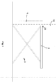
- Fig. 1 shows the new ironing board in profile with the ironing board (2) in the open state
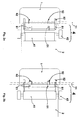
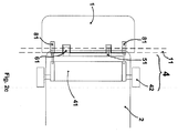
- Fig. 2a, 2b and 2c show schematically the system of locks and quick connectors (4) for the connection of electrical and vapor lines of the ironing board (2) in the open state with a vertical, freestanding or permanently installed support structure (1) and
- Fig. 3 shows a plan view of the ironing board (2) where two fan wheels (71, 72) are visible, both of which are connected to the respective embedded in the ironing board engine, which is not shown.
- the new ironing board consists of a support structure (1) for at least one pivoting ironing board (2); the support structure (1) is either columnar free-standing or fixed to the wall (11) or mounted in a piece of furniture.
- the ironing board (2) is fixed on one side (21) movable on the support structure (1) and can be brought from the closed state in which the ironing board (2) is practically parallel to the support structure (1) in the open state in which the ironing board (2) is raised and in a horizontal position opposite the ground, as shown illustration 1 seen. To fold, proceed in reverse order.
- the new ironing board may also have legs (3) supporting the ironing board (2) and the legs in illustration 1 are shown with dashed lines.
- the ironing board (2) of the new ironing board is equipped with suction and / or blowing device and / or electrically heated and / or provided with a ventilation system and / or has a system for generating steam.
- the new ironing board has at least one locking system with quick connections (4) for the connection of the electrical and steam lines between the support structure (1) and ironing board (2).
- the new ironing board has one or more mobile connections for the electrical lines (61) and / or the steam lines (51) installed in the ironing board (2) and the carrier structure (1) are and which allow connection to the relevant fixed connections for the electrical (62) and / or the steam lines (52) in the support structure (1) and / or in the ironing board (2) at the height of the mobile terminals (51 , 61) are installed when the ironing board (2) is in the open state, as out illustration 1 seen.
- the system of quick connections (4) is equipped with at least one eccentrically rotating element (41), which is embedded in the ironing board (2) or in the support structure (1) and with a rotary handle (42) and with one or both mobile terminals (51, 61) is connected.
- a rotary handle (42) and with one or both mobile terminals (51, 61) is connected.
- the rotary handle (42) one acts on the eccentric (41), which rotates horizontally to the ironing board (2), and causes the mobile terminals (51, 61) to the fixed terminals (52, 62) are in the support structure (1) or in the ironing board (2) are connected.
- a solution is preferred where the quick-connect system (4) is incorporated in the ironing board (2); Also, the eccentric (41) is installed in the ironing board (2) and is connected to a rotary handle (42) and the two mobile terminals (51, 61).
- the rotation of the rotary handle (42) causes a displacement of the eccentric (41) horizontally to the ironing board (2) and perpendicular to the edge (21) of the ironing board (2), so that the mobile terminals (51, 61) at this edge (21) - / retract and to the fixed terminals (52, 62), which are located in the support structure (1), couple / of the fixed terminals (52, 62) solve.
- the system of quick connectors (4) may be located in the support structure (1).
- the eccentric (41) is installed in the support structure (1) and is connected to a rotary handle (42) and the two mobile terminals (51, 61), which are also incorporated in the support structure (1).
- the rotation of the rotary handle (42) causes a displacement of the eccentric (41) horizontally to the open ironing board (2) and perpendicular to the edge (21) of the ironing board (2) so that the mobile terminals (51, 61) from the support structure (1) in Extend / retract the edge (21) of the ironing board (2) and connect to the fixed connections (52, 62) located in the ironing board (2) / release from the fixed connections (52, 62).
- the latching system with quick connections (4) also ensures that the ironing board (2) is locked.
- the Verrastungssystem (4) of one or better two centering pins (81) which are moved when rotating the eccentric (41), perpendicular from the edge (21) of the ironing board (2) extend and in opposite in the support structure (1) engage the bushings (82).
- a first, at least partial rotation causes the retraction and thus release of the mobile terminals (51, 61) and the second, at least partial rotation also the retraction of the centering pins 81, which are released from the bushings (82) and release the ironing board (2) which can be brought from the open to the closed, vertical position.
- the pins (81) may also operate without eccentric (41) via other mechanisms, such as springs or automatic devices, which cause the bolts 81 to extend / retract into / out of the bushes (82) when the ironing board (2 ) in horizontal Position is opened.
- the bolts (81) can be triggered for example via a snap system.
- the new ironing board also provides that in the ironing table (2) two motors for the suction / blowing device instead of one are incorporated, which are in communication with the respective, also in the ironing board (2) installed fan wheel (71, 72). These motors are lower in horsepower than a single one, run in the same direction of rotation at the same time, and ensure effective extraction / blowing while reducing the noise level by half compared with a single motor.
- the problem of the noise of the ironing boards with suction / blowing device has great importance and is not solved in the current state of the art.
Landscapes
- Engineering & Computer Science (AREA)
- Textile Engineering (AREA)
- Irons (AREA)
Abstract
Description
- Die Erfindung betrifft ein Bügelbrett mit einer Trägerstruktur für wenigstens einen schwenkbaren Bügeltisch mit Verrastungssystem und Schnellanschlüssen für die Verbindung von elektrischen Leitungen und Dampfleitungen zwischen Bügeltisch und Trägerstruktur.
- Es gibt verschiedene Arten von tragbaren Bügelbrettern, deren Bügeltisch waagrecht ausgerichtet wird und der von Standbeinen oder Trägerstrukturen verschiedener Bauweise die am Boden aufliegen und mit diesem nicht fest verbunden sind, getragen wird. Es gibt Bügelbretter mit vertikaler Trägerstruktur, die am Boden steht und an deren Seite ein klappbarer Bügeltisch angebracht ist. Es gibt Bügelbretter, die entweder an der Wand montiert oder in einem Möbelstück eingebaut sind und über einen klappbaren Bügeltisch verfügen, der an der fixen Trägerstruktur angebracht ist. Die Bügeltische sind über Scharniere mit der jeweiligen Trägerstruktur - freistehend oder fest installiert - verbunden und können von der waagrechten Arbeitsstellung heraus in den geschlossenen Zustand, in der der Bügeltisch praktisch parallel zur Trägerstruktur oder zur Wand steht, gebracht werden. Auf diese Weise nimmt das Bügelbrett, wenn es nicht gebraucht wird, wenig Platz ein.
- Es gibt Bügelbretter deren Bügeltisch beheizbar und mit Absaug- und Blasvorrichtung versehen ist, sowie solche die beheizbar oder mit Belüftungssystem für die Trocknung ausgestattet sind. Besagte Bügelbretter sind mit einem Motor und wenigstens einem Lüfterrad versehen, die im Bügeltisch installiert sind. Der Nachteil dieser Bügelbretter besteht hauptsächlich im Geräusch, das sie entwickeln.
- Weiter sind Dampfgeneratoren, Motoren und die elektrischen Verbindungen zum Bügeltisch für gewöhnlich in den Bügeltisch selbst integriert. Der Nachteil dieser Bügelbretter besteht darin, dass ein Bügeltisch, in dem diese Bauteile untergebracht sind, beträchtliches Gewicht und Stärke hat und sperrig ist.
- Der durchschnittlich kräftige Benutzer hat daher seine Schwierigkeiten mit diesem Bügelbrett und diesem Bügeltisch umzugehen, besonders wenn er geöffnet bzw. zusammengeklappt, verstellt oder transportiert werden soll.
- Der Erfindung liegt somit die Aufgabe zu Grunde, ein klappbares Bügelbrett mit einer Trägerstruktur oder Festmontage mit wenigstens einem schwenkbaren Bügeltisch mit Verrastungssystem und Schnellanschlüssen für die Verbindung der elektrischen und Dampfleitungen zwischen Bügeltisch und Trägerstruktur mit reduziertem Platzbedarf, Stärke und Gewicht des Bügeltisches bereitzustellen, bei dem das Öffnen und Zusammenklappen des Bügeltisches bequemer und handlicher durchzuführen ist.
- Erfindungsgemäß wird die Aufgabe durch ein Bügelbrett mit den Merkmalen des Patentanspruchs 1 gelöst. Vorteilhafte Ausgestaltungen und Weiterbildungen der Erfindung ergeben sich aus den nachfolgenden abhängigen Ansprüchen.
- Das erfindungsgemäße Bügelbrett hat ferner den Vorteil, dass eine schnelle und einfache Verbindung der elektrischen Leitungen und Dampfleitungen zwischen Trägerstruktur und Bügeltisch bereitgestellt wird, ohne dass zusätzliche Kabel oder Leitungen nötig sind, die die Handgriffe zum Öffnen und Schwenken des Bügeltisches, das Bügeln und den eventuellen Transport des Bügelbretts erschweren. Hierzu sind einige Bauteile, beispielsweise der Dampfgenerator, praktisch in der Trägerstruktur des Bügeltisches und nicht im Bügeltisch selbst untergebracht.
- Die elektrische Verbindung und jene der Dampfleitung ist nur möglich, wenn der Bügeltisch geöffnet ist und sich in waagrechter Stellung befindet.
- Ein weiterer Vorteil der Erfindung besteht darin den Bügeltisch in waagrechter, geöffneter Stellung bequem und/oder automatisch einzurasten.
- Ein weiterer Zweck der Erfindung ist, das Geräusch bei Betrieb der Absaug- bzw. Blasvorrichtung zu reduzieren.
- Für diese und andere direkte und zusätzliche Zweckbestimmungen ist das neue klappbare Bügelbrett mit vertikaler Trägerstruktur oder fest installiert und mit wenigstens einem schwenkbaren Bügeltisch, Schnellanschlüssen für die Verbindung der elektrischen und Dampfleitungen zwischen Bügeltisch und Trägerstruktur, geeignet.
- Das neuartige Bügelbrett besteht hauptsächlich aus wenigstens einer vertikalen Trägerstruktur mit wenigstens einem Bügeltisch. Die Trägerstruktur bildet die Führungsschiene, die das Schwenken des eventuell mit Standbeinen versehenen Bügeltisches, der an dieser Trägerstruktur angebracht ist, erlaubt. Die Trägerstruktur kann ein säulenartiges Gebilde sein, das am Boden steht, oder an der Wand oder in einem Möbelstück fest installiert sein.
- Ein Verrastungssystem mit Schnellanschlüssen, das den Bügeltisch fest einrasten lässt, ermöglich die Verbindung der elektrischen und der Dampfleitungen, wenn sich der Bügeltisch in waagrechter geöffneter Stellung befindet.
- Der Bügeltisch ist also schwenkbar, d.h. er lässt sich aus dem geschlossenen Zustand, in dem sich der Tisch im Grunde parallel zur Trägerstruktur befindet, in den geöffneten Zustand bringen. Im geöffneten Zustand befindet sich der Bügeltisch in waagrechter Lage und im Bezug auf den Boden auf einer gewissen Höhe. Die Bewegung ist auch in umgekehrter Reihenfolge möglich.
- Der Bügeltisch des neuen Bügelbretts ist mit einer Absaug- und/oder Blasvorrichtung ausgestattet und/oder elektrisch beheizbar und/oder mit einem Belüftungssystem versehen und/oder verfügt über ein System zur Dampferzeugung.
- Schwenkt der Benutzer den Bügeltisch in die waagrechte geöffnete Stellung, kann er, dank des Verrastungssystems mit Schnellanschlüssen, den Bügeltisch schnell und automatisch in dieser waagrechten Lage blockieren und die Verbindung der elektrischen und Dampfleitungen zwischen Trägerstruktur und Bügeltisch mit einfachen Handgriffen vornehmen.
- Das neue Bügelbrett verfügt nämlich über ein innovatives System von Schnellanschlüssen für die Verbindung der elektrischen und Dampfleitungen zwischen Trägerstruktur und Bügeltisch, die nur dann hergestellt ist, wenn sich der Bügeltisch in waagrechter Stellung befindet.
- Das neue Bügelbrett ist vorzugsweise auch mit zwei Motoren ausgestattet, die ebenfalls in den Bügeltisch integrierte Lüfterräder gleichzeitig und in derselben Laufrichtung antreiben.
- Die Merkmale der Erfindung sind genauer in der folgenden Beschreibung erklärt, die sich auf die Zeichnungen bezieht, die als nicht einschränkendes Beispiel beiliegen.
-
Fig. 1 zeigt das neue Bügelbrett im Profil mit dem Bügeltisch (2) in geöffnetem Zustand; -
Fig. 2a, 2b und2c zeigen schematisch das System der Verrastungen und Schnellanschlüsse (4) für die Verbindung elektrischer und Dampfleitungen des Bügeltisches (2) in geöffnetem Zustand mit einer vertikalen, freistehenden oder fest installierten Trägerstruktur (1) und -
Fig. 3 zeigt eine Aufsicht des Bügeltisches (2) wo zwei Lüfterräder (71, 72) ersichtlich sind, die beide an den jeweiligen im Bügeltisch eingelassenen Motor, der nicht abgebildet ist, angeschlossen sind. - Das neue Bügelbrett besteht aus einer Trägerstruktur (1) für wenigstens einen schwenkbaren Bügeltisch (2); die Trägerstruktur (1) ist entweder äulenartig freistehend oder fest an der Wand (11) montiert oder in einem Möbelstück eingebaut. Der Bügeltisch (2) ist auf einer Seite (21) beweglich an der Trägerstruktur (1) fixiert und kann so aus dem geschlossenen Zustand, in dem der Bügeltisch (2) praktisch parallel zur Trägerstruktur (1) steht, in den geöffneten Zustand gebracht werden, in dem der Bügeltisch (2) in die Höhe gehoben wird und sich in waagrechter Position gegenüber dem Boden befindet, wie aus
Abbildung 1 ersichtlich. Zum Zusammenklappen verfährt man in umgekehrter Reihenfolge. Das neue Bügelbrett kann auch über Standbeine (3) verfügen, die den Bügeltisch (2) stützen und die inAbbildung 1 mit gestrichelten Linien dargestellt sind. - Der Bügeltisch (2) des neuen Bügelbretts ist mit Absaug- und/oder Blasvorrichtung ausgestattet und/oder elektrisch beheizbar und/oder mit einem Belüftungssystem versehen und/oder verfügt über ein System zur Dampferzeugung.
- Das neue Bügelbrett verfügt über wenigstens ein Verrastungssystem mit Schnellanschlüssen (4) für die Verbindung der elektrischen und Dampfleitungen zwischen Trägerstruktur (1) und Bügeltisch (2).
- Wie in den Abbildungen 2a und 2c schematisch angegeben, verfügt das neue Bügelbrett über ein oder mehrere mobile Anschlüsse für die elektrischen Leitungen (61) und/oder die Dampfleitungen (51), die in den Bügeltisch (2) und die Trägerstruktur (1) eingebaut sind und die den Anschluss an die diesbezüglichen festen Anschlüsse für die elektrischen (62) und/oder die Dampfleitungen (52) ermöglichen, die in die Trägerstruktur (1) und/oder in den Bügeltisch (2) auf der Höhe der mobilen Anschlüsse (51, 61) eingebaut sind, wenn der Bügeltisch (2) in geöffnetem Zustand ist, wie aus
Abbildung 1 ersichtlich. - Im Rahmen der Umsetzung wird das System der Schnellanschlüsse (4) mit wenigstens einem exzentrisch rotierenden Element (41) ausgestattet, das in den Bügeltisch (2) oder in der Trägerstruktur (1) eingelassen und mit einem Drehgriff (42) und mit einem oder beiden mobilen Anschlüssen (51, 61) verbunden ist. Dreht man am Drehgriff (42) wirkt man auf den Exzenter (41) ein, der sich horizontal zum Bügeltisch (2) dreht, und bewirkt, dass die mobilen Anschlüsse (51, 61) an die fixen Anschlüsse (52, 62), die sich in der Trägerstruktur (1) oder im Bügeltisch (2) befinden, angeschlossen werden.
- Vorgezogen wird eine Lösung wo das Schnellanschluss-System (4) in den Bügeltisch (2) eingearbeitet ist; auch der Exzenter (41) ist im Bügeltisch (2) installiert und ist mit einem Drehgriff (42) und den beiden mobilen Anschlüssen (51, 61) verbunden.
- Das Drehen des Drehgriffes (42) bewirkt eine Verschiebung des Exzenters (41) horizontal zum Bügeltisch (2) und rechtwinklig zur Kante (21) des Bügeltisches (2), sodass die mobilen Anschlüsse (51, 61) an dieser Kante (21) aus-/einfahren und sich an die fixen Anschlüsse (52, 62), die sich in der Trägerstruktur (1) befinden, ankoppeln/ von den fixen Anschlüssen (52, 62) lösen.
- Alternativ zu dieser Lösung kann sich das System der Schnellanschlüsse (4) in der Trägerstruktur (1) befinden. Der Exzenter (41) ist in der Trägerstruktur (1) installiert und ist mit einem Drehgriff (42) und den beiden mobilen Anschlüssen (51, 61) verbunden, die ebenfalls in die Trägerstruktur (1) eingearbeitet sind.
- Das Drehen des Drehgriffes (42) bewirkt eine Verschiebung des Exzenters (41) horizontal zum geöffneten Bügeltisch (2) und rechtwinklig zur Kante (21) des Bügeltisches (2) sodass die mobilen Anschlüsse (51, 61) aus der Trägerstruktur (1) in die Kante (21) des Bügeltisches (2) aus-/einfahren und sich an die fixen Anschlüsse (52, 62), die sich im Bügeltisch (2) befinden, ankoppeln/ von den fixen Anschlüssen (52, 62) lösen.
- Das Verrastungssystem mit Schnellanschlüssen (4) sorgt auch für das Feststellen des Bügeltisches (2). Vorzugsweise besteht das Verrastungssystem (4) aus einem oder besser zwei Zentrierungsbolzen (81), die beim Drehen des Exzenters (41) bewegt werden, rechtwinklig aus der Kante (21) des Bügeltisches (2) ausfahren und in gegenüberliegende in der Trägerstruktur (1) eingearbeitete Buchsen (82) einrasten.
- Wie aus den Abbildungen 2a, 2b, 2c ersichtlich, ist vorgesehen, dass bei einer ersten, wenigstens teilweisen Drehung des Drehgriffes (42) die Zentrierungsbolzen (81) in die Buchsen (82) einrasten und ein zweites, wenigstens teilweises Drehen des Drehgriffes (42) das Ausfahren der mobilen Anschlüsse (51, 61) bewirkt, die sich dann an die festen Anschlüsse (52, 62) ankoppeln. Um das Entkoppeln des Bügeltisches (2) von der Trägerstruktur (1) zu erreichen, muss der Benutzer den Drehgriff (42) in entgegengesetzte Richtung drehen. Eine erste, wenigstens teilweise Drehung bewirkt das Einfahren und damit Lösen der mobilen Anschlüsse (51, 61) und die zweite, wenigstens teilweise Drehung auch das Einfahren der Zentrierungsbolzen 81, die sich aus den Buchsen (82) lösen und den Bügeltisch (2) freigeben, der damit aus der offenen in die geschlossene, vertikale Stellung gebracht werden kann.
- Alternativ dazu können die Bolzen (81) auch ohne Exzenter (41) über andere Mechanismen agieren, wie beispielsweise Federn oder automatische Vorrichtungen, die das Ein-/Ausfahren der Bolzen 81 in/aus den Buchsen (82) bewirken, wenn der Bügeltisch (2) in waagrechter Stellung geöffnet wird. So können die Bolzen (81) beispielsweise über ein Schnappsystem ausgelöst werden.
- Das neue Bügelbrett sieht auch vor, dass in den Bügeltisch (2) zwei Motoren für die Absaug-/Blasvorrichtung statt einem eingearbeitet werden, die mit dem jeweiligen, ebenfalls im Bügeltisch (2) installierten Lüfterrad (71, 72) in Verbindung stehen. Diese Motoren verfügen über eine geringere Leistung als ein einzelner, laufen gleichzeitig in dieselbe Drehrichtung und sichern wirksame Absaug-/Blaswirkung, während die Geräuschentwicklung, gegenüber einem einzelnen Motor, um die Hälfte reduziert wird. Die Problematik der Geräuschentwicklung der Bügelbretter mit Absaug-/Blasvorrichtung hat große Bedeutung und ist beim heutigen Stand der Technik nicht gelöst.
- Es ist vorgesehen in die Trägerstruktur (1) eigene Nischen einzuarbeiten, die Objekte oder Zubehör, wie etwa ein Bügeleisen, einen Dampfkessel usw. - fest oder herausnehmbar - aufnehmen können.
- Diese schematische Beschreibung reicht einer erfahrenen Person, um die Erfindung herzustellen; in der Folge kann es, im Zuge der konkreten Umsetzung, Varianten geben, die die Substanz des innovativen Konzepts aber unangetastet lassen.
Claims (13)
- Klappbares Bügelbrett mit einem nicht beheizbaren und/oder elektrisch beheizbaren, mit Saug- und/oder Blasvorrichtung und/oder Dampfgenerator und/oder Lüftungssystem zur Trocknung versehenen Bügeltisch (2) und Standvorrichtungen oder -füßen (1, 3) für den Bügeltisch (2), umfassend:- wenigstens eine vertikale, säulenartige freistehende oder an der Wand oder in einem Möbelstück fest installierte Trägerstruktur (1) des Bügeltisches (2), wobei der Bügeltisch (2) auf einer Seite (21) beweglich an der Trägerstruktur (1) gelagert bzw. geführt ist und so aus dem geschlossenen Zustand, in dem der Bügeltisch (2) im Wesentlichen parallel zur Trägerstruktur (1) steht, in geöffnete, waagrechte Stellung gebracht werden kann;- ein oder mehrere mobile Anschlüsse (61, 51) für Leitungen vom Dampfgenerator oder vom Lüftungssystem, die an der Kante (21), an der der Bügeltisch (2) zur Trägerstruktur(1) weist und/oder in die Trägerstruktur (1) selbst eingearbeitet sind;- ein oder mehrere fixe Anschlüsse (62, 52) für die Leitungen, die sich in der Trägerstruktur(1) und/oder an der Kante (21), an der der Bügeltisch (2) mit der Trägerstruktur (1) verbunden werden kann, in geöffneter Stellung des Bügeltisches (2), die die betriebsgemäße Aufstellposition bildet, auf der Höhe der mobilen Anschlüsse (51, 61) befinden, wobei die mobilen Anschlüsse (51, 61) sich verschieben lassen und an die fixen Anschlüsse (52, 62) ankoppeln oder von diesen lösen, wenn sich der Bügeltisch (2) in geöffneter Stellung befindet.
- Klappbares Bügelbrett nach Anspruch 1,
dadurch gekennzeichnet,
dass die mobilen Anschlüsse für die elektrischen (61) und/oder die Dampfleitungen (51) und die fixen Anschlüsse für die elektrischen (62) und/oder die Dampfleitungen (52) bestimmt sind. - Klappbares Bügelbrett nach Anspruch 1,
dadurch gekennzeichnet,
dass es wenigstens ein Verrastungssystem mit Schnellanschlüssen (4) besitzt, mit dem die mobilen Anschlüsse (51, 61) mit den festen (52, 62) gekoppelt werden können und das über ein exzentrisch rotierendes (41) oder parallel fahrendes Bauteil verfügt, das an einen oder mehreren der mobilen Anschlüsse (51, 61) gekoppelt ist und wo die Bewegung des exzentrisch rotierenden (41) oder parallel zum Bügeltisch (2) fahrenden Bauteils das Aus-/Einfahren besagter mobiler Anschlüsse (51, 62) und damit die Ankoppelung, bzw. das Lösen an die fixen Anschlüsse (52, 62) bewirkt. - Klappbares Bügelbrett nach einem der Ansprüche 1 bis 3,
dadurch gekennzeichnet,
dass der Exzenter (41) oder das bewegliche Teil und die mobilen Anschlüsse (51, 61) in den Bügeltisch (2) eingearbeitet sind; Exzenter (41) oder bewegliches Teil sind mit einem außen liegenden Drehgriff (42) verbunden, während die fixen Anschlüsse (52, 62) an entsprechender Position in die Trägerstruktur (1) eingebaut sind. - Klappbares Bügelbrett nach einem der Ansprüche 1 bis 3,
dadurch gekennzeichnet,
dass der Exzenter (41) oder das bewegliche Teil und die mobilen Anschlüsse (51, 61) in die Trägerstruktur (1) eingearbeitet sind; Exzenter (41) oder bewegliches Teil sind mit einem außen liegenden Drehgriff (42) verbunden, während die fixen Anschlüsse (52, 62) an entsprechender Position in den Bügeltisch (2) eingebaut sind. - Klappbares Bügelbrett nach Anspruch 4 oder 5,
dadurch gekennzeichnet,
dass das Verrastungssystem mit Schnellanschlüssen (4) aus einem oder mehreren Zentrierungsbolzen (81) besteht, der/die an der Kante (21) des Bügeltisches (2) eingebaut ist/sind, wo dieser an der Trägerstruktur (1) fixiert ist, sodass die Zentrierungsbolzen (81) in gegenüberliegende, in der Trägerstruktur (1) eingearbeitete Buchsen (82) gleiten können. - Klappbares Bügelbrett nach Anspruch 4 oder 5,
dadurch gekennzeichnet,
dass das Verrastungssystem mit Schnellanschlüssen (4) aus einem oder mehreren Zentrierungsbolzen (81) besteht, das/die in der Trägerstruktur eingebaut ist/sind sodass die Zentrierungsbolzen (81) in gegenüberliegende, in den geöffneten Bügeltisch (2) eingearbeitete Buchsen (82) gleiten können. - Klappbares Bügelbrett nach Anspruch 6 oder 7
dadurch gekennzeichnet,
dass die Zentrierungsbolzen (81) mit dem Exzenter (41) verbunden sind, der seinerseits über einen Drehgriff (42) verfügt, wobei das Drehen des Drehgriffs (42) die Verschiebung des Exzenters (41) und gleichzeitig die Vorwärts- bzw. Rückwärtsbewegung der Zentrierungsbolzen (81) bewirkt. - Klappbares Bügelbrett nach Anspruch 8,
dadurch gekennzeichnet,
dass bei einer ersten, wenigstens teilweisen Drehung des Drehgriffes (42) die Zentrierungsbolzen (81) in die Buchsen (82) einrasten und ein zweites, wenigstens teilweises Drehen des Drehgriffes (42) in dieselbe Richtung das Ausfahren der mobilen Anschlüsse (51, 61) bewirkt, die sich dann an die festen Anschlüsse (52, 62) ankoppeln. - Klappbares Bügelbrett nach Anspruch 8 oder 9,
dadurch gekennzeichnet,
dass bei einer ersten, wenigstens teilweisen Drehung des Drehgriffes (42) die mobilen Anschlüsse (51, 61) sich von den festen Anschlüssen (52, 62) lösen und ein zweites, wenigstens teilweises Drehen des Drehgriffes (42) in dieselbe Richtung das Zurückfahren des/der Zentrierungsbolzen (81) aus den Buchsen (82) und damit das Lösen des Bügeltisches (2) bewirken. - Klappbares Bügelbrett nach einem der Ansprüche 4 bis 10,
dadurch gekennzeichnet,
dass an jeder Längsseite des Bügeltisches au ßenseitig jeweils ein separater Drehgriff (42) angebracht ist, die jeweils mit dem Exzenter (41) oder beweglichen Teil verbunden sind. - Klappbares Bügelbrett nach einem der Ansprüche 1 bis 11,
dadurch gekennzeichnet,
dass es über wenigstens zwei Motoren mit identischer Rotationsrichtung verfügt, die ihrerseits mit Lüfterrädern (71, 72) verbunden und in den Bügeltisch (2) eingebaut sind. - Klappbares Bügelbrett nach einem der Ansprüche 1 bis 11,
dadurch gekennzeichnet,
dass die Trägerstruktur (1) Nischen zur Aufnahme von einem fest eingebauten oder herausnehmbaren Dampfgenerator, einem Bügeleisen, und/oder einem Wassertank und/oder zum Verstauen von Zubehör umfasst.
Priority Applications (1)
| Application Number | Priority Date | Filing Date | Title |
|---|---|---|---|
| PL09401018T PL2169109T3 (pl) | 2008-09-30 | 2009-09-15 | Składana deska do prasowania z szybkozłączem na przewody |
Applications Claiming Priority (1)
| Application Number | Priority Date | Filing Date | Title |
|---|---|---|---|
| ITPD2008A000277A IT1394994B1 (it) | 2008-09-30 | 2008-09-30 | Asse da stiro richiudibile con piano di stiratura ribaltabile e connessione rapida elettrica e del vapore |
Publications (2)
| Publication Number | Publication Date |
|---|---|
| EP2169109A1 true EP2169109A1 (de) | 2010-03-31 |
| EP2169109B1 EP2169109B1 (de) | 2012-06-20 |
Family
ID=40756836
Family Applications (1)
| Application Number | Title | Priority Date | Filing Date |
|---|---|---|---|
| EP09401018A Active EP2169109B1 (de) | 2008-09-30 | 2009-09-15 | Klappbares Bügelbrett mit Schnellverschluss für Leitungen |
Country Status (4)
| Country | Link |
|---|---|
| EP (1) | EP2169109B1 (de) |
| ES (1) | ES2387635T3 (de) |
| IT (1) | IT1394994B1 (de) |
| PL (1) | PL2169109T3 (de) |
Citations (6)
| Publication number | Priority date | Publication date | Assignee | Title |
|---|---|---|---|---|
| US2201701A (en) * | 1938-08-27 | 1940-05-21 | Carl E Newstrom | Wall inset ironing table |
| EP0126530A2 (de) * | 1983-03-28 | 1984-11-28 | Gemini Clothescare Limited | Vorrichtung zum Bügeln oder Pressen von Wäsche |
| EP0587472A1 (de) * | 1992-08-28 | 1994-03-16 | Seb S.A. | Dampfbügeltisch |
| GB2328449A (en) | 1997-08-21 | 1999-02-24 | Brian Day | Foldable ironing board. |
| GB2397072A (en) | 2003-01-10 | 2004-07-14 | George Docker | Combined trouser press and ironing board |
| US7278229B1 (en) * | 2006-09-05 | 2007-10-09 | Whitney Design, Inc. | Ironing board storage device |
-
2008
- 2008-09-30 IT ITPD2008A000277A patent/IT1394994B1/it active
-
2009
- 2009-09-15 PL PL09401018T patent/PL2169109T3/pl unknown
- 2009-09-15 EP EP09401018A patent/EP2169109B1/de active Active
- 2009-09-15 ES ES09401018T patent/ES2387635T3/es active Active
Patent Citations (6)
| Publication number | Priority date | Publication date | Assignee | Title |
|---|---|---|---|---|
| US2201701A (en) * | 1938-08-27 | 1940-05-21 | Carl E Newstrom | Wall inset ironing table |
| EP0126530A2 (de) * | 1983-03-28 | 1984-11-28 | Gemini Clothescare Limited | Vorrichtung zum Bügeln oder Pressen von Wäsche |
| EP0587472A1 (de) * | 1992-08-28 | 1994-03-16 | Seb S.A. | Dampfbügeltisch |
| GB2328449A (en) | 1997-08-21 | 1999-02-24 | Brian Day | Foldable ironing board. |
| GB2397072A (en) | 2003-01-10 | 2004-07-14 | George Docker | Combined trouser press and ironing board |
| US7278229B1 (en) * | 2006-09-05 | 2007-10-09 | Whitney Design, Inc. | Ironing board storage device |
Also Published As
| Publication number | Publication date |
|---|---|
| ES2387635T3 (es) | 2012-09-27 |
| EP2169109B1 (de) | 2012-06-20 |
| IT1394994B1 (it) | 2012-08-07 |
| ITPD20080277A1 (it) | 2010-04-01 |
| PL2169109T3 (pl) | 2012-09-28 |
Similar Documents
| Publication | Publication Date | Title |
|---|---|---|
| DE3344791A1 (de) | Gepaeckwagen | |
| DE3932142A1 (de) | Einstiegsstufenanordnung fuer wohnmobile | |
| DE202023104603U1 (de) | Klapptisch | |
| DE202025104128U1 (de) | Eine zusammenklappbare Babytrage und ein diese umfassender Kinderwagen | |
| EP3802272B1 (de) | Beförderungsvorrichtung und beförderungsfahrzeug | |
| EP2169109B1 (de) | Klappbares Bügelbrett mit Schnellverschluss für Leitungen | |
| DE68902733T2 (de) | Tapeziertisch fuer anstreicher, zusammenklappbar und mit variablen abmessungen. | |
| EP0185105A1 (de) | Zerlegbarer Möbelkorpus | |
| AT524026A4 (de) | Tisch mit mehreren Tischplatten | |
| EP0804897B1 (de) | Bodenreinigungsmaschine, insbesondere Scheuersaugmaschine | |
| DE202019100106U1 (de) | Klappvorrichtung für ein Multifunktionsmöbel | |
| DE102016008259B4 (de) | Klappstuhl | |
| DE10144353A1 (de) | Innenstellage für ein Motorfahrzeug | |
| DE202019103922U1 (de) | Möbeleinheit | |
| WO2012065776A1 (de) | Arbeitstisch, insbesondere für den werkstattbereich | |
| DE3230378C2 (de) | Elektrische Geräte-Steckvorrichtung für Wohnwagen oder dergleichen Campingfahrzeuge | |
| WO1991013201A1 (de) | Bügelmaschine mit einer drehbaren bügelwalze und einer mit ihr zusammenwirkenden beheizbaren bügelmulde | |
| DE202025103366U1 (de) | Scharnierstruktur sowie Freischaltstruktur eines klappbaren Schubwagens | |
| DE8601683U1 (de) | Mobiltelefonkoffer | |
| DE102023120683A1 (de) | Tisch mit Photovoltaikfunktion | |
| EP4590621A1 (de) | Zerlegbare vorrichtung für den transport von gegenständen und das heben von menschen | |
| DE10010201C1 (de) | Höhenverstellbare Kopfstütze | |
| DE76372C (de) | Ausziehtisch | |
| DE102024124290A1 (de) | Klapptisch, Wandelement, Anordnung und Fahrzeug | |
| DE1938825U (de) | Tragbarer apparat zum grillen von lebensmitteln. |
Legal Events
| Date | Code | Title | Description |
|---|---|---|---|
| PUAI | Public reference made under article 153(3) epc to a published international application that has entered the european phase |
Free format text: ORIGINAL CODE: 0009012 |
|
| AK | Designated contracting states |
Kind code of ref document: A1 Designated state(s): AT BE BG CH CY CZ DE DK EE ES FI FR GB GR HR HU IE IS IT LI LT LU LV MC MK MT NL NO PL PT RO SE SI SK SM TR |
|
| AX | Request for extension of the european patent |
Extension state: AL BA RS |
|
| 17P | Request for examination filed |
Effective date: 20100529 |
|
| GRAP | Despatch of communication of intention to grant a patent |
Free format text: ORIGINAL CODE: EPIDOSNIGR1 |
|
| RIC1 | Information provided on ipc code assigned before grant |
Ipc: D06F 81/06 20060101AFI20111130BHEP |
|
| GRAS | Grant fee paid |
Free format text: ORIGINAL CODE: EPIDOSNIGR3 |
|
| GRAA | (expected) grant |
Free format text: ORIGINAL CODE: 0009210 |
|
| AK | Designated contracting states |
Kind code of ref document: B1 Designated state(s): AT BE BG CH CY CZ DE DK EE ES FI FR GB GR HR HU IE IS IT LI LT LU LV MC MK MT NL NO PL PT RO SE SI SK SM TR |
|
| REG | Reference to a national code |
Ref country code: GB Ref legal event code: FG4D Free format text: NOT ENGLISH |
|
| REG | Reference to a national code |
Ref country code: CH Ref legal event code: EP |
|
| REG | Reference to a national code |
Ref country code: AT Ref legal event code: REF Ref document number: 563150 Country of ref document: AT Kind code of ref document: T Effective date: 20120715 |
|
| REG | Reference to a national code |
Ref country code: IE Ref legal event code: FG4D Free format text: LANGUAGE OF EP DOCUMENT: GERMAN |
|
| REG | Reference to a national code |
Ref country code: DE Ref legal event code: R096 Ref document number: 502009003846 Country of ref document: DE Effective date: 20120816 |
|
| REG | Reference to a national code |
Ref country code: GB Ref legal event code: 746 Effective date: 20120731 |
|
| REG | Reference to a national code |
Ref country code: ES Ref legal event code: GC2A Effective date: 20120814 |
|
| REG | Reference to a national code |
Ref country code: DE Ref legal event code: R084 Ref document number: 502009003846 Country of ref document: DE Effective date: 20120702 |
|
| REG | Reference to a national code |
Ref country code: ES Ref legal event code: FG2A Ref document number: 2387635 Country of ref document: ES Kind code of ref document: T3 Effective date: 20120927 |
|
| REG | Reference to a national code |
Ref country code: PL Ref legal event code: LICE Effective date: 20120726 Ref country code: PL Ref legal event code: T3 |
|
| PG25 | Lapsed in a contracting state [announced via postgrant information from national office to epo] |
Ref country code: FI Free format text: LAPSE BECAUSE OF FAILURE TO SUBMIT A TRANSLATION OF THE DESCRIPTION OR TO PAY THE FEE WITHIN THE PRESCRIBED TIME-LIMIT Effective date: 20120620 Ref country code: NO Free format text: LAPSE BECAUSE OF FAILURE TO SUBMIT A TRANSLATION OF THE DESCRIPTION OR TO PAY THE FEE WITHIN THE PRESCRIBED TIME-LIMIT Effective date: 20120920 Ref country code: SE Free format text: LAPSE BECAUSE OF FAILURE TO SUBMIT A TRANSLATION OF THE DESCRIPTION OR TO PAY THE FEE WITHIN THE PRESCRIBED TIME-LIMIT Effective date: 20120620 Ref country code: LT Free format text: LAPSE BECAUSE OF FAILURE TO SUBMIT A TRANSLATION OF THE DESCRIPTION OR TO PAY THE FEE WITHIN THE PRESCRIBED TIME-LIMIT Effective date: 20120620 |
|
| REG | Reference to a national code |
Ref country code: NL Ref legal event code: VDEP Effective date: 20120620 |
|
| REG | Reference to a national code |
Ref country code: LT Ref legal event code: MG4D Effective date: 20120613 |
|
| PG25 | Lapsed in a contracting state [announced via postgrant information from national office to epo] |
Ref country code: LV Free format text: LAPSE BECAUSE OF FAILURE TO SUBMIT A TRANSLATION OF THE DESCRIPTION OR TO PAY THE FEE WITHIN THE PRESCRIBED TIME-LIMIT Effective date: 20120620 Ref country code: GR Free format text: LAPSE BECAUSE OF FAILURE TO SUBMIT A TRANSLATION OF THE DESCRIPTION OR TO PAY THE FEE WITHIN THE PRESCRIBED TIME-LIMIT Effective date: 20120921 Ref country code: HR Free format text: LAPSE BECAUSE OF FAILURE TO SUBMIT A TRANSLATION OF THE DESCRIPTION OR TO PAY THE FEE WITHIN THE PRESCRIBED TIME-LIMIT Effective date: 20120620 Ref country code: SI Free format text: LAPSE BECAUSE OF FAILURE TO SUBMIT A TRANSLATION OF THE DESCRIPTION OR TO PAY THE FEE WITHIN THE PRESCRIBED TIME-LIMIT Effective date: 20120620 |
|
| PG25 | Lapsed in a contracting state [announced via postgrant information from national office to epo] |
Ref country code: CY Free format text: LAPSE BECAUSE OF FAILURE TO SUBMIT A TRANSLATION OF THE DESCRIPTION OR TO PAY THE FEE WITHIN THE PRESCRIBED TIME-LIMIT Effective date: 20120620 Ref country code: RO Free format text: LAPSE BECAUSE OF FAILURE TO SUBMIT A TRANSLATION OF THE DESCRIPTION OR TO PAY THE FEE WITHIN THE PRESCRIBED TIME-LIMIT Effective date: 20120620 Ref country code: CZ Free format text: LAPSE BECAUSE OF FAILURE TO SUBMIT A TRANSLATION OF THE DESCRIPTION OR TO PAY THE FEE WITHIN THE PRESCRIBED TIME-LIMIT Effective date: 20120620 Ref country code: IS Free format text: LAPSE BECAUSE OF FAILURE TO SUBMIT A TRANSLATION OF THE DESCRIPTION OR TO PAY THE FEE WITHIN THE PRESCRIBED TIME-LIMIT Effective date: 20121020 Ref country code: EE Free format text: LAPSE BECAUSE OF FAILURE TO SUBMIT A TRANSLATION OF THE DESCRIPTION OR TO PAY THE FEE WITHIN THE PRESCRIBED TIME-LIMIT Effective date: 20120620 Ref country code: SK Free format text: LAPSE BECAUSE OF FAILURE TO SUBMIT A TRANSLATION OF THE DESCRIPTION OR TO PAY THE FEE WITHIN THE PRESCRIBED TIME-LIMIT Effective date: 20120620 |
|
| PG25 | Lapsed in a contracting state [announced via postgrant information from national office to epo] |
Ref country code: PT Free format text: LAPSE BECAUSE OF FAILURE TO SUBMIT A TRANSLATION OF THE DESCRIPTION OR TO PAY THE FEE WITHIN THE PRESCRIBED TIME-LIMIT Effective date: 20121022 |
|
| PG25 | Lapsed in a contracting state [announced via postgrant information from national office to epo] |
Ref country code: NL Free format text: LAPSE BECAUSE OF FAILURE TO SUBMIT A TRANSLATION OF THE DESCRIPTION OR TO PAY THE FEE WITHIN THE PRESCRIBED TIME-LIMIT Effective date: 20120620 |
|
| BERE | Be: lapsed |
Owner name: MIELE & CIE. K.G. Effective date: 20120930 |
|
| PLBE | No opposition filed within time limit |
Free format text: ORIGINAL CODE: 0009261 |
|
| STAA | Information on the status of an ep patent application or granted ep patent |
Free format text: STATUS: NO OPPOSITION FILED WITHIN TIME LIMIT |
|
| PG25 | Lapsed in a contracting state [announced via postgrant information from national office to epo] |
Ref country code: DK Free format text: LAPSE BECAUSE OF FAILURE TO SUBMIT A TRANSLATION OF THE DESCRIPTION OR TO PAY THE FEE WITHIN THE PRESCRIBED TIME-LIMIT Effective date: 20120620 Ref country code: MC Free format text: LAPSE BECAUSE OF NON-PAYMENT OF DUE FEES Effective date: 20120930 |
|
| 26N | No opposition filed |
Effective date: 20130321 |
|
| REG | Reference to a national code |
Ref country code: IE Ref legal event code: MM4A |
|
| REG | Reference to a national code |
Ref country code: DE Ref legal event code: R097 Ref document number: 502009003846 Country of ref document: DE Effective date: 20130321 |
|
| PG25 | Lapsed in a contracting state [announced via postgrant information from national office to epo] |
Ref country code: BE Free format text: LAPSE BECAUSE OF NON-PAYMENT OF DUE FEES Effective date: 20120930 Ref country code: BG Free format text: LAPSE BECAUSE OF FAILURE TO SUBMIT A TRANSLATION OF THE DESCRIPTION OR TO PAY THE FEE WITHIN THE PRESCRIBED TIME-LIMIT Effective date: 20120920 Ref country code: IE Free format text: LAPSE BECAUSE OF NON-PAYMENT OF DUE FEES Effective date: 20120915 |
|
| PG25 | Lapsed in a contracting state [announced via postgrant information from national office to epo] |
Ref country code: MT Free format text: LAPSE BECAUSE OF FAILURE TO SUBMIT A TRANSLATION OF THE DESCRIPTION OR TO PAY THE FEE WITHIN THE PRESCRIBED TIME-LIMIT Effective date: 20120620 |
|
| REG | Reference to a national code |
Ref country code: CH Ref legal event code: PL |
|
| PG25 | Lapsed in a contracting state [announced via postgrant information from national office to epo] |
Ref country code: SM Free format text: LAPSE BECAUSE OF FAILURE TO SUBMIT A TRANSLATION OF THE DESCRIPTION OR TO PAY THE FEE WITHIN THE PRESCRIBED TIME-LIMIT Effective date: 20120620 Ref country code: LU Free format text: LAPSE BECAUSE OF NON-PAYMENT OF DUE FEES Effective date: 20120915 |
|
| PG25 | Lapsed in a contracting state [announced via postgrant information from national office to epo] |
Ref country code: CH Free format text: LAPSE BECAUSE OF NON-PAYMENT OF DUE FEES Effective date: 20130930 Ref country code: LI Free format text: LAPSE BECAUSE OF NON-PAYMENT OF DUE FEES Effective date: 20130930 Ref country code: HU Free format text: LAPSE BECAUSE OF FAILURE TO SUBMIT A TRANSLATION OF THE DESCRIPTION OR TO PAY THE FEE WITHIN THE PRESCRIBED TIME-LIMIT Effective date: 20090915 |
|
| PG25 | Lapsed in a contracting state [announced via postgrant information from national office to epo] |
Ref country code: MK Free format text: LAPSE BECAUSE OF FAILURE TO SUBMIT A TRANSLATION OF THE DESCRIPTION OR TO PAY THE FEE WITHIN THE PRESCRIBED TIME-LIMIT Effective date: 20120620 |
|
| REG | Reference to a national code |
Ref country code: AT Ref legal event code: MM01 Ref document number: 563150 Country of ref document: AT Kind code of ref document: T Effective date: 20140915 |
|
| PG25 | Lapsed in a contracting state [announced via postgrant information from national office to epo] |
Ref country code: AT Free format text: LAPSE BECAUSE OF NON-PAYMENT OF DUE FEES Effective date: 20140915 |
|
| REG | Reference to a national code |
Ref country code: FR Ref legal event code: PLFP Year of fee payment: 8 |
|
| REG | Reference to a national code |
Ref country code: FR Ref legal event code: PLFP Year of fee payment: 9 |
|
| REG | Reference to a national code |
Ref country code: FR Ref legal event code: PLFP Year of fee payment: 10 |
|
| P01 | Opt-out of the competence of the unified patent court (upc) registered |
Effective date: 20230529 |
|
| PGFP | Annual fee paid to national office [announced via postgrant information from national office to epo] |
Ref country code: TR Payment date: 20230904 Year of fee payment: 15 Ref country code: IT Payment date: 20230920 Year of fee payment: 15 Ref country code: GB Payment date: 20230926 Year of fee payment: 15 |
|
| PGFP | Annual fee paid to national office [announced via postgrant information from national office to epo] |
Ref country code: PL Payment date: 20230817 Year of fee payment: 15 Ref country code: FR Payment date: 20230926 Year of fee payment: 15 |
|
| PGFP | Annual fee paid to national office [announced via postgrant information from national office to epo] |
Ref country code: ES Payment date: 20231018 Year of fee payment: 15 |
|
| GBPC | Gb: european patent ceased through non-payment of renewal fee |
Effective date: 20240915 |
|
| PG25 | Lapsed in a contracting state [announced via postgrant information from national office to epo] |
Ref country code: GB Free format text: LAPSE BECAUSE OF NON-PAYMENT OF DUE FEES Effective date: 20240915 |
|
| PG25 | Lapsed in a contracting state [announced via postgrant information from national office to epo] |
Ref country code: IT Free format text: LAPSE BECAUSE OF NON-PAYMENT OF DUE FEES Effective date: 20240915 |
|
| PG25 | Lapsed in a contracting state [announced via postgrant information from national office to epo] |
Ref country code: FR Free format text: LAPSE BECAUSE OF NON-PAYMENT OF DUE FEES Effective date: 20240930 |
|
| PGFP | Annual fee paid to national office [announced via postgrant information from national office to epo] |
Ref country code: DE Payment date: 20250930 Year of fee payment: 17 |
|
| REG | Reference to a national code |
Ref country code: ES Ref legal event code: FD2A Effective date: 20251030 |
|
| PG25 | Lapsed in a contracting state [announced via postgrant information from national office to epo] |
Ref country code: ES Free format text: LAPSE BECAUSE OF NON-PAYMENT OF DUE FEES Effective date: 20240916 |
|
| PG25 | Lapsed in a contracting state [announced via postgrant information from national office to epo] |
Ref country code: PL Free format text: LAPSE BECAUSE OF NON-PAYMENT OF DUE FEES Effective date: 20240915 |
|
| PG25 | Lapsed in a contracting state [announced via postgrant information from national office to epo] |
Ref country code: TR Free format text: LAPSE BECAUSE OF NON-PAYMENT OF DUE FEES Effective date: 20240915 |