EP2168807A1 - Molette de commande avec indicateurs lumineux - Google Patents
Molette de commande avec indicateurs lumineux Download PDFInfo
- Publication number
- EP2168807A1 EP2168807A1 EP09170423A EP09170423A EP2168807A1 EP 2168807 A1 EP2168807 A1 EP 2168807A1 EP 09170423 A EP09170423 A EP 09170423A EP 09170423 A EP09170423 A EP 09170423A EP 2168807 A1 EP2168807 A1 EP 2168807A1
- Authority
- EP
- European Patent Office
- Prior art keywords
- mode
- state
- indicator
- control wheel
- function
- Prior art date
- Legal status (The legal status is an assumption and is not a legal conclusion. Google has not performed a legal analysis and makes no representation as to the accuracy of the status listed.)
- Granted
Links
- 238000000034 method Methods 0.000 claims abstract description 5
- 230000004913 activation Effects 0.000 claims description 4
- 238000005286 illumination Methods 0.000 claims description 2
- 230000003213 activating effect Effects 0.000 abstract 1
- 230000008859 change Effects 0.000 description 3
- 230000000007 visual effect Effects 0.000 description 3
- 241001508691 Martes zibellina Species 0.000 description 2
- 238000004378 air conditioning Methods 0.000 description 2
- 239000004576 sand Substances 0.000 description 2
- 230000008033 biological extinction Effects 0.000 description 1
- 239000003086 colorant Substances 0.000 description 1
- 230000000694 effects Effects 0.000 description 1
- 238000012986 modification Methods 0.000 description 1
- 230000004048 modification Effects 0.000 description 1
Images
Classifications
-
- B—PERFORMING OPERATIONS; TRANSPORTING
- B60—VEHICLES IN GENERAL
- B60K—ARRANGEMENT OR MOUNTING OF PROPULSION UNITS OR OF TRANSMISSIONS IN VEHICLES; ARRANGEMENT OR MOUNTING OF PLURAL DIVERSE PRIME-MOVERS IN VEHICLES; AUXILIARY DRIVES FOR VEHICLES; INSTRUMENTATION OR DASHBOARDS FOR VEHICLES; ARRANGEMENTS IN CONNECTION WITH COOLING, AIR INTAKE, GAS EXHAUST OR FUEL SUPPLY OF PROPULSION UNITS IN VEHICLES
- B60K6/00—Arrangement or mounting of plural diverse prime-movers for mutual or common propulsion, e.g. hybrid propulsion systems comprising electric motors and internal combustion engines ; Control systems therefor, i.e. systems controlling two or more prime movers, or controlling one of these prime movers and any of the transmission, drive or drive units Informative references: mechanical gearings with secondary electric drive F16H3/72; arrangements for handling mechanical energy structurally associated with the dynamo-electric machine H02K7/00; machines comprising structurally interrelated motor and generator parts H02K51/00; dynamo-electric machines not otherwise provided for in H02K see H02K99/00
- B60K6/20—Arrangement or mounting of plural diverse prime-movers for mutual or common propulsion, e.g. hybrid propulsion systems comprising electric motors and internal combustion engines ; Control systems therefor, i.e. systems controlling two or more prime movers, or controlling one of these prime movers and any of the transmission, drive or drive units Informative references: mechanical gearings with secondary electric drive F16H3/72; arrangements for handling mechanical energy structurally associated with the dynamo-electric machine H02K7/00; machines comprising structurally interrelated motor and generator parts H02K51/00; dynamo-electric machines not otherwise provided for in H02K see H02K99/00 the prime-movers consisting of electric motors and internal combustion engines, e.g. HEVs
- B60K6/42—Arrangement or mounting of plural diverse prime-movers for mutual or common propulsion, e.g. hybrid propulsion systems comprising electric motors and internal combustion engines ; Control systems therefor, i.e. systems controlling two or more prime movers, or controlling one of these prime movers and any of the transmission, drive or drive units Informative references: mechanical gearings with secondary electric drive F16H3/72; arrangements for handling mechanical energy structurally associated with the dynamo-electric machine H02K7/00; machines comprising structurally interrelated motor and generator parts H02K51/00; dynamo-electric machines not otherwise provided for in H02K see H02K99/00 the prime-movers consisting of electric motors and internal combustion engines, e.g. HEVs characterised by the architecture of the hybrid electric vehicle
- B60K6/44—Series-parallel type
-
- B60K35/28—
-
- B—PERFORMING OPERATIONS; TRANSPORTING
- B60—VEHICLES IN GENERAL
- B60K—ARRANGEMENT OR MOUNTING OF PROPULSION UNITS OR OF TRANSMISSIONS IN VEHICLES; ARRANGEMENT OR MOUNTING OF PLURAL DIVERSE PRIME-MOVERS IN VEHICLES; AUXILIARY DRIVES FOR VEHICLES; INSTRUMENTATION OR DASHBOARDS FOR VEHICLES; ARRANGEMENTS IN CONNECTION WITH COOLING, AIR INTAKE, GAS EXHAUST OR FUEL SUPPLY OF PROPULSION UNITS IN VEHICLES
- B60K6/00—Arrangement or mounting of plural diverse prime-movers for mutual or common propulsion, e.g. hybrid propulsion systems comprising electric motors and internal combustion engines ; Control systems therefor, i.e. systems controlling two or more prime movers, or controlling one of these prime movers and any of the transmission, drive or drive units Informative references: mechanical gearings with secondary electric drive F16H3/72; arrangements for handling mechanical energy structurally associated with the dynamo-electric machine H02K7/00; machines comprising structurally interrelated motor and generator parts H02K51/00; dynamo-electric machines not otherwise provided for in H02K see H02K99/00
- B60K6/20—Arrangement or mounting of plural diverse prime-movers for mutual or common propulsion, e.g. hybrid propulsion systems comprising electric motors and internal combustion engines ; Control systems therefor, i.e. systems controlling two or more prime movers, or controlling one of these prime movers and any of the transmission, drive or drive units Informative references: mechanical gearings with secondary electric drive F16H3/72; arrangements for handling mechanical energy structurally associated with the dynamo-electric machine H02K7/00; machines comprising structurally interrelated motor and generator parts H02K51/00; dynamo-electric machines not otherwise provided for in H02K see H02K99/00 the prime-movers consisting of electric motors and internal combustion engines, e.g. HEVs
- B60K6/42—Arrangement or mounting of plural diverse prime-movers for mutual or common propulsion, e.g. hybrid propulsion systems comprising electric motors and internal combustion engines ; Control systems therefor, i.e. systems controlling two or more prime movers, or controlling one of these prime movers and any of the transmission, drive or drive units Informative references: mechanical gearings with secondary electric drive F16H3/72; arrangements for handling mechanical energy structurally associated with the dynamo-electric machine H02K7/00; machines comprising structurally interrelated motor and generator parts H02K51/00; dynamo-electric machines not otherwise provided for in H02K see H02K99/00 the prime-movers consisting of electric motors and internal combustion engines, e.g. HEVs characterised by the architecture of the hybrid electric vehicle
- B60K6/48—Parallel type
-
- G—PHYSICS
- G05—CONTROLLING; REGULATING
- G05G—CONTROL DEVICES OR SYSTEMS INSOFAR AS CHARACTERISED BY MECHANICAL FEATURES ONLY
- G05G1/00—Controlling members, e.g. knobs or handles; Assemblies or arrangements thereof; Indicating position of controlling members
- G05G1/08—Controlling members for hand actuation by rotary movement, e.g. hand wheels
- G05G1/10—Details, e.g. of discs, knobs, wheels or handles
- G05G1/105—Details, e.g. of discs, knobs, wheels or handles comprising arrangements for illumination
-
- B60K2360/172—
-
- B—PERFORMING OPERATIONS; TRANSPORTING
- B60—VEHICLES IN GENERAL
- B60K—ARRANGEMENT OR MOUNTING OF PROPULSION UNITS OR OF TRANSMISSIONS IN VEHICLES; ARRANGEMENT OR MOUNTING OF PLURAL DIVERSE PRIME-MOVERS IN VEHICLES; AUXILIARY DRIVES FOR VEHICLES; INSTRUMENTATION OR DASHBOARDS FOR VEHICLES; ARRANGEMENTS IN CONNECTION WITH COOLING, AIR INTAKE, GAS EXHAUST OR FUEL SUPPLY OF PROPULSION UNITS IN VEHICLES
- B60K6/00—Arrangement or mounting of plural diverse prime-movers for mutual or common propulsion, e.g. hybrid propulsion systems comprising electric motors and internal combustion engines ; Control systems therefor, i.e. systems controlling two or more prime movers, or controlling one of these prime movers and any of the transmission, drive or drive units Informative references: mechanical gearings with secondary electric drive F16H3/72; arrangements for handling mechanical energy structurally associated with the dynamo-electric machine H02K7/00; machines comprising structurally interrelated motor and generator parts H02K51/00; dynamo-electric machines not otherwise provided for in H02K see H02K99/00
- B60K6/20—Arrangement or mounting of plural diverse prime-movers for mutual or common propulsion, e.g. hybrid propulsion systems comprising electric motors and internal combustion engines ; Control systems therefor, i.e. systems controlling two or more prime movers, or controlling one of these prime movers and any of the transmission, drive or drive units Informative references: mechanical gearings with secondary electric drive F16H3/72; arrangements for handling mechanical energy structurally associated with the dynamo-electric machine H02K7/00; machines comprising structurally interrelated motor and generator parts H02K51/00; dynamo-electric machines not otherwise provided for in H02K see H02K99/00 the prime-movers consisting of electric motors and internal combustion engines, e.g. HEVs
- B60K6/22—Arrangement or mounting of plural diverse prime-movers for mutual or common propulsion, e.g. hybrid propulsion systems comprising electric motors and internal combustion engines ; Control systems therefor, i.e. systems controlling two or more prime movers, or controlling one of these prime movers and any of the transmission, drive or drive units Informative references: mechanical gearings with secondary electric drive F16H3/72; arrangements for handling mechanical energy structurally associated with the dynamo-electric machine H02K7/00; machines comprising structurally interrelated motor and generator parts H02K51/00; dynamo-electric machines not otherwise provided for in H02K see H02K99/00 the prime-movers consisting of electric motors and internal combustion engines, e.g. HEVs characterised by apparatus, components or means specially adapted for HEVs
-
- B—PERFORMING OPERATIONS; TRANSPORTING
- B60—VEHICLES IN GENERAL
- B60W—CONJOINT CONTROL OF VEHICLE SUB-UNITS OF DIFFERENT TYPE OR DIFFERENT FUNCTION; CONTROL SYSTEMS SPECIALLY ADAPTED FOR HYBRID VEHICLES; ROAD VEHICLE DRIVE CONTROL SYSTEMS FOR PURPOSES NOT RELATED TO THE CONTROL OF A PARTICULAR SUB-UNIT
- B60W50/00—Details of control systems for road vehicle drive control not related to the control of a particular sub-unit, e.g. process diagnostic or vehicle driver interfaces
- B60W50/08—Interaction between the driver and the control system
- B60W50/14—Means for informing the driver, warning the driver or prompting a driver intervention
- B60W2050/146—Display means
-
- H—ELECTRICITY
- H01—ELECTRIC ELEMENTS
- H01H—ELECTRIC SWITCHES; RELAYS; SELECTORS; EMERGENCY PROTECTIVE DEVICES
- H01H9/00—Details of switching devices, not covered by groups H01H1/00 - H01H7/00
- H01H9/18—Distinguishing marks on switches, e.g. for indicating switch location in the dark; Adaptation of switches to receive distinguishing marks
- H01H9/182—Illumination of the symbols or distinguishing marks
-
- Y—GENERAL TAGGING OF NEW TECHNOLOGICAL DEVELOPMENTS; GENERAL TAGGING OF CROSS-SECTIONAL TECHNOLOGIES SPANNING OVER SEVERAL SECTIONS OF THE IPC; TECHNICAL SUBJECTS COVERED BY FORMER USPC CROSS-REFERENCE ART COLLECTIONS [XRACs] AND DIGESTS
- Y02—TECHNOLOGIES OR APPLICATIONS FOR MITIGATION OR ADAPTATION AGAINST CLIMATE CHANGE
- Y02T—CLIMATE CHANGE MITIGATION TECHNOLOGIES RELATED TO TRANSPORTATION
- Y02T10/00—Road transport of goods or passengers
- Y02T10/60—Other road transportation technologies with climate change mitigation effect
- Y02T10/62—Hybrid vehicles
Definitions
- the present invention generally relates to a control wheel for a motor vehicle comprising a first fixed part on which are arranged function indicators in correspondence of which are provided light indicators and a second portion rotatable relative to the first portion for controlling the activation of said functions. More particularly, the invention relates to a control wheel for a hybrid motor vehicle.
- a control unit for an automatic air conditioning system for a vehicle comprises in particular a rotary knob comprising a visual indication for setting a set value of an air conditioning function.
- Light indication means are provided to indicate the set reference value.
- Such a control device does not make it possible to indicate to the user, on the one hand, the state (active / inactive) of the various controlled functions and, on the other hand, the availability or unavailability of the controlled functions.
- the use of a rotary knob on which is arranged an indicator is generally not very aesthetic.
- An object of the present invention is to meet the various disadvantages of the prior art mentioned above and in particular, first of all, to provide a control wheel to clearly indicate to the user the state of each of the functions controlled by the wheel while preserving an attractive design.
- a first aspect of the invention relates to a control wheel for a motor vehicle comprising a first fixed part on which function indicators are arranged in correspondence of which at least as many light indicators are provided and a second part without movable indicator with respect to the first part for controlling the activation of said functions, characterized in that each of the indicator lights comprises a first state indicating that the corresponding function is activated, a second state indicating that the corresponding function is deactivated and available, and a third state indicating that the corresponding function is deactivated and unavailable.
- a wheel makes it possible to indicate the active function and the inactive functions while indicating for them whether they are available or not.
- such a tri-state indicator system makes it possible to dispense with the use of an indicator on the mobile part of the wheel, thus making the assembly more aesthetic.
- the second part is rotatable relative to the first part.
- the indication of availability provided by the second state indicates that the corresponding function is possible
- the indication of availability provided by the third state indicates that the corresponding function is impossible.
- the indication of availability provided by the second state indicates that the corresponding function is advisable and possible
- the indication of availability provided by the third state indicates that the corresponding function is deprecated or impossible.
- the first state is indicated by means of a first color
- the second state by means of a second color
- the third state by the absence of illumination or the use of a third color. color of the corresponding indicator light.
- the first fixed part is formed by a central disk
- the second rotary part is formed by a ring concentric with the central disk
- a hybrid motor vehicle comprising an electric motor and a heat engine
- at least two function indicators are provided on the fixed part of the wheel, a first indicator designating an automatic mode in which the vehicle automatically manages the use of one and / or the other of the engines and a second indicator designating a zero emission mode in which the vehicle uses only the electric motor.
- four function indicators are provided on the fixed part of the wheel, a third indicator designating a sport mode in which the two motors are used to provide more torque to move the vehicle and a fourth indicator designating a four wheel mode. drive in which two wheels are driven by the engine and the other two wheels are led by the electric monitor.
- the invention relates to a method of actuating a control wheel according to the first aspect of the invention, characterized in that the indicator light of the active function is in the first state, the indicator lights deactivated functions are in the second state for the available functions and in the third state for the unavailable functions.
- the light indicators 5 are arranged on a fixed ring 6, concentric with the central disk 7 also fixed, forming the central assembly 2.
- the indicator lights are arranged below the function indicators, all the indicators being located in the fixed central disk.
- the wheel 1 comprises a second movable portion 3, advantageously in the form of a ring or a rotary ring concentric with respect to the first fixed portion 2. Note that preferably no indication is provided on this rotating ring , so as to improve the general design of the wheel 1.
- the second part 3 rotates allows to control the activation of the functions indicated on the inner part 2 fixed. For this, the user must simply rotate the outer portion 3 opposite the function indication that it wishes to activate.
- the originality lies in the luminous indicators used.
- the numerical references used are the same as those of the figure 1a .
- the "AUTO" mode is activated, the other modes are deactivated.
- the indicator light 5a corresponding to the "AUTO” mode is in a first state, for example lit in a first color. From the current mode, here the "AUTO" mode, it happens that one or more of the other possible modes are not available, while the remaining modes are.
- each indicator light 5 has in addition to the first state, the active mode indicated by the ignition in a first color, a second a state indicating that the corresponding mode is deactivated and available and a third state indicating that the corresponding mode is deactivated and unavailable.
- the second state is achieved by lighting the indicator light in a second color
- the third state is achieved either by the absence of ignition of the indicator light, or by the ignition of this indicator in a third color.
- Such a light indicator is obtained for example by using two light-emitting diodes of different colors, or three depending on the desired color effects.
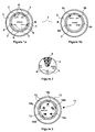
- a green diode may mean that the mode is active while an orange diode may indicate that the mode is inactive but available. So on the example shown in figure 1b , the "ZEV" mode is deactivated and unavailable, the light indicator 5b is off, and the "4WD” and “SPORT” modes are deactivated and available, the light indicators 5c and 5d being lit in a second color, different from that of indicator 5a.
- a control button not shown, allowing the user to switch between a manual operating mode and an assisted operating mode.
- the availability indication provided by the second state indicates that the corresponding function is possible
- the availability indication provided by the third state indicates that the corresponding function is impossible.
- Such a manual mode of operation allows the user to force a deprecated mode if it is not impossible.
- the availability indication provided by the second state indicates that the corresponding function is advisable and possible
- the availability indication provided by the third state indicates that the corresponding function is deprecated or impossible.
- the figure 2 represents the fixed central portion 2 of a control wheel according to an embodiment variant of the first mode.
- the light indicators 5 are arranged directly on the central disk 7, with the exception of the light indicator for the "AUTO" mode, which is designed as a skylight 8, which is lit in a first color when the mode is active and a second color when the mode is inactive and available.
- light indicators 15 are associated with each of the activatable modes 14a to 14e. These light indicators 15 have three states. A first state indicating that the corresponding function or mode is activated. A second state indicating that the corresponding function or mode is disabled and available. Finally a third state indicating that the corresponding function or mode is deactivated and unavailable. In this way the user can act on the rotating annular portion 13 around the fixed central portion 12 to change mode while being aware of the available and unavailable modes and the active mode by the color play of the various indicators.
- the invention relates to a method of actuating a control wheel according to one of the embodiments presented above.
- the indicator light of the active function is in the first state, while the indicators of the deactivated functions are in the second state for the available functions and in the third state for the unavailable functions.
- a control wheel (as Figures 1a and 1b ) of several modes of operation using the electric machine and / or the thermal machine of a motor vehicle equipped with a hybrid powertrain, to clearly inform the user of the vehicle concerning the availability of the active mode of operation. It may also be desirable to inform the user about the possible unavailability of the other inactive modes.
- the indicator light corresponding to the activated operating mode is lit in a first state (eg green) to indicate that this mode is active.
- the wheel includes alert means for preventing in the event of unavailability of the active mode of operation during taxiing, these warning means being implemented by the passage into a second state of the corresponding light indicator. in the active mode for a predetermined period of time.
- This second state is for example achieved by the flashing (switching on and off) of the indicator light corresponding to the active operating mode become unavailable for a predetermined period of time.
- this second state can be achieved by the successive switching on and off of one then the other of the diodes.
- the visual indicator of the unavailable mode is placed in a third state indicating that it is no longer active while another mode of operation is activated (by default the system can go into the AUTO mode) .
- This third state can correspond either to the extinction of the visual indicator or to the ignition in another color (eg orange).
- Such a command dial simply warns the user that the active mode is no longer available while indicating the new mode enabled.
- a light indicator performs two different functions, a first function of indicating to the user whether the corresponding mode is active or not and a second function of alerting the user when the active mode becomes unavailable.
- means may be provided for transmitting a message indicating the unavailability of the active operating mode.
- This message is preferably transmitted to the user in the form of a display of the desired information on a screen of the vehicle.
- audible warning means used to indicate an impossibility to continue in the active mode of operation due to a failure of the hybrid powertrain.
- audible warning means allows the user to distinguish a change of mode due to the conditions of use of the vehicle, a change of mode due to a failure of the hybrid powertrain.
Abstract
Description
- La présente invention concerne de manière générale une molette de commande pour véhicule automobile comprenant une première partie fixe sur laquelle sont disposées des indicateurs de fonction en correspondance desquels sont prévus des indicateurs lumineux et une deuxième partie rotative par rapport à la première partie pour commander l'activation desdites fonctions. Plus particulièrement, l'invention concerne une molette de commande pour véhicule automobile hybride.
- Il est connu dans l'art antérieur, notamment du document
EP 0 814 965 , un appareil de commande pour système automatique de climatisation pour véhicule. Cet appareil de commande comprend notamment un bouton tournant comprenant une indication visuelle pour régler une valeur de consigne d'une fonction de climatisation. Des moyens d'indication lumineux sont prévus pour indiquer la valeur de consigne réglée. Un tel appareil de commande ne permet pas d'indiquer à l'utilisateur, d'une part, l'état (actif / inactif) des différentes fonctions commandées et, d'autre part, la disponibilité ou l'indisponibilité des fonctions commandées. En outre, l'utilisation d'un bouton tournant sur lesquels est agencé un indicateur n'est en général pas très esthétique. - Un but de la présente invention est de répondre aux différents inconvénients de l'art antérieur mentionnés ci-dessus et en particulier, tout d'abord, de fournir une molette de commande permettant de clairement indiquer à l'utilisateur l'état de chacune des fonctions commandées par la molette tout en préservant un design attractif.
- Pour cela un premier aspect de l'invention concerne une molette de commande pour véhicule automobile comprenant une première partie fixe sur laquelle sont disposées des indicateurs de fonction en correspondance desquels sont prévus au moins autant d'indicateurs lumineux et une deuxième partie sans indicateur mobile par rapport à la première partie pour commander l'activation desdites fonctions, caractérisée en ce que chacun des indicateurs lumineux comprend un premier état indiquant que la fonction correspondante est activée, un deuxième état indiquant que la fonction correspondante est désactivée et disponible, et un troisième état indiquant que la fonction correspondante est désactivée et indisponible. Une telle molette permet bien d'indiquer la fonction active et les fonctions inactives tout en indiquant pour ces dernières si elles sont disponibles ou non. En outre, un tel système d'indicateur lumineux à trois états permet de s'affranchir de l'utilisation d'un indicateur sur la partie mobile de la molette rendant ainsi l'ensemble plus esthétique.
- Selon une variante de réalisation avantageuse, la deuxième partie est mobile en rotation par rapport à la première partie.
- Selon une autre variante de réalisation avantageuse, dans un premier mode de fonctionnement dit « manuel », l'indication de disponibilité fournie par le deuxième état indique que la fonction correspondante est possible, et l'indication de disponibilité fournie par le troisième état indique que la fonction correspondante est impossible. Dans un deuxième mode de fonctionnement dit « assisté », l'indication de disponibilité fournie par le deuxième état indique que la fonction correspondante est conseillée et possible, et l'indication de disponibilité fournie par le troisième état indique que la fonction correspondante est déconseillée ou impossible.
- Selon une autre variante de réalisation avantageuse, le premier état est indiqué au moyen d'une première couleur, le deuxième état au moyen d'une deuxième couleur et le troisième état par l'absence d'illumination ou l'utilisation d'une troisième couleur de l'indicateur lumineux correspondant.
- Selon une autre variante de réalisation avantageuse, la première partie fixe est formée par un disque central, et la deuxième partie rotative est formée par un anneau concentrique au disque central.
- Selon une autre variante de réalisation avantageuse pour un véhicule automobile hybride comprenant un moteur électrique et un moteur thermique, au moins deux indicateurs de fonction sont prévus sur la partie fixe de la molette, un premier indicateur désignant un mode automatique dans lequel le véhicule gère automatiquement l'utilisation de l'un et/ou de l'autre des moteurs et un deuxième indicateur désignant un mode d'émission zéro dans lequel le véhicule utilise uniquement le moteur électrique. Avantageusement, quatre indicateurs de fonction sont prévus sur la partie fixe de la molette, un troisième indicateur désignant un mode sport dans lequel les deux moteurs sont utilisés de manière à fournir plus de couple pour déplacer le véhicule et un quatrième indicateur désignant un mode quatre roues motrices dans lequel deux roues sont emmenées par le moteur thermique et les deux autres roues sont emmenées par le moniteur électrique.
- Selon un deuxième aspect, l'invention concerne un procédé d'actionnement d'une molette de commande selon le premier aspect de l'invention, caractérisé en ce que l'indicateur lumineux de la fonction active est dans le premier état, les indicateurs lumineux des fonctions désactivées sont dans le deuxième état pour les fonctions disponibles et dans le troisième état pour les fonctions indisponibles.
- D'autres caractéristiques et avantages de la présente invention apparaîtront plus clairement à la lecture de la description détaillée qui suit de modes de réalisation de l'invention donnés à titre d'exemples nullement limitatifs et illustrés par le dessin annexé, dans lesquels :
- les
figures 1a et 1b représentent une molette de commande selon un premier mode de réalisation de la présente invention ; - la
figure 2 représente une molette de commande selon une variante du premier mode de réalisation ; - la
figure 3 représente une molette de commande selon un deuxième mode de réalisation. - L'invention sera décrite ci-après uniquement à titre d'exemple non limitatif en relation avec les
figures 1a à 3 . - La
figure 1a représente une molette de commande selon un premier mode de réalisation de la présente invention. La molette 1 comprend une première partie fixe 2, située de préférence au centre et en forme de disque, sur laquelle sont disposées des indicateurs de fonction 4 en correspondance desquels sont agencés des indicateurs lumineux 5. Le premier mode de réalisation, représenté ici, concerne une molette de commande pour un véhicule automobile de type hybride, c'est-à-dire comprenant un premier moteur électrique et un deuxième moteur thermique. À titre d'exemple, les fonctions commandées par cette molette 1 peuvent être les quatre modes de fonctionnement énumérés ci-après : - -- un mode « AUTO », sélectionné par défaut au démarrage, dans lequel la sélection entre le moteur électrique et le moteur thermique ou les deux est géré automatiquement par le véhicule ;
- -- un mode « SPORT » utilisant les deux moteurs électrique et thermique, et dans lequel le passage des rapports est plus court, un couple plus important étant délivré au moyen du moteur électrique ;
- -- un mode « 4WD » dans lequel sont utilisées les quatre roues motrices, deux roues étant emmenées par le moteur thermique, les deux autres roues étant emmenées par le moteur électrique.
- -- un mode «ZEV» (pour Zero Emission Vehicle), dans lequel uniquement le moteur électrique est utilisé.
- Selon une première variante de réalisation (
figures 1a et 1b ), les indicateurs lumineux 5 sont agencés sur un anneau fixe 6, concentrique au disque central 7 également fixe, formant l'ensemble central 2. Selon une deuxième variante de réalisation (figure 2 ), les indicateurs lumineux sont agencés en dessous des indicateurs de fonction, tous les indicateurs étant situés dans le disque central fixe. - Se référant de nouveau à la
figure 1a , la molette 1 comprend une deuxième partie 3 mobile, avantageusement sous la forme d'une bague ou d'un anneau rotatif concentrique par rapport à la première partie fixe 2. On notera que de préférence aucune indication n'est prévue sur cet anneau rotatif, de sorte à améliorer le design général de la molette 1. La deuxième partie 3 rotative permet de commander l'activation des fonctions indiquées sur la partie intérieure 2 fixe. Pour cela, l'utilisateur doit tout simplement faire tourner la partie extérieure 3 en regard de l'indication de fonction qu'il désire activer. - Considérant maintenant la
figure 1b , sur laquelle est représentée une molette identique à celle de lafigure 1a , l'originalité réside dans les indicateurs lumineux utilisés. Les références numériques utilisées sont les mêmes que celles de lafigure 1a . Sur l'exemple représenté à lafigure 1b , le mode « AUTO » est activé, les autres modes étant désactivés. Pour indiquer clairement à l'utilisateur dans quel mode le véhicule fonctionne, l'indicateur lumineux 5a correspondant au mode « AUTO » est dans un premier état, par exemple allumé dans une première couleur. À partir du mode courant, ici le mode « AUTO », il arrive qu'un ou plusieurs des autres modes possibles ne soient pas disponibles, tandis que les modes restants le sont. Pour permettre à l'utilisateur de distinguer un mode désactivé disponible d'un mode désactivé indisponible, il est avantageusement prévu que chaque indicateur lumineux 5 présente en sus du premier état, i.e. mode actif indiqué par l'allumage dans une première couleur, un deuxième état indiquant que le mode correspondant est désactivé et disponible et un troisième état indiquant que le mode correspondant est désactivé et indisponible. De préférence le deuxième état est réalisé par l'allumage de l'indicateur lumineux dans une deuxième couleur, tandis que le troisième état est réalisé soit par l'absence d'allumage de l'indicateur lumineux, soit par l'allumage de cet indicateur dans une troisième couleur. Un tel indicateur lumineux est obtenu par exemple en utilisant deux diodes électroluminescentes de couleurs différentes, ou trois selon les effets de couleurs souhaités. Une diode de couleur verte pourra signifier que le mode est actif tandis qu'une diode de couleur orange pourra signifier que le mode est inactif mais disponible. Ainsi sur l'exemple représenté à lafigure 1b , le mode «ZEV» est désactivé et indisponible, l'indicateur lumineux 5b étant éteint, et les modes «4WD» et «SPORT» sont désactivés et disponibles, les indicateurs lumineux 5c et 5d étant allumés dans une deuxième couleur, différente de celle de l'indicateur 5a. - Selon une variante de réalisation, il est prévu un bouton de commande, non représenté, permettant à l'utilisateur de basculer entre un mode de fonctionnement manuel et un mode de fonctionnement assisté. Dans le premier mode de fonctionnement manuel, l'indication de disponibilité fournie par le deuxième état indique que la fonction correspondante est possible, et l'indication de disponibilité fournie par le troisième état indique que la fonction correspondante est impossible. Un tel mode de fonctionnement manuel permet à l'utilisateur de forcer un mode déconseillé s'il n'est pas impossible. Dans le deuxième mode de fonctionnement assisté, l'indication de disponibilité fournie par le deuxième état indique que la fonction correspondante est conseillée et possible, et l'indication de disponibilité fournie par le troisième état indique que la fonction correspondante est déconseillée ou impossible.
- La
figure 2 représente la partie centrale fixe 2 d'une molette de commande selon une variante de réalisation du premier mode. Dans cette variante, les indicateurs lumineux 5 sont agencés directement sur le disque central 7, à l'exception de l'indicateur lumineux pour le mode «AUTO» qui est réalisé sous la forme d'un puits de lumière 8, qui est allumé dans une première couleur lorsque le mode est actif et dont une deuxième couleur lorsque le mode est inactif et disponible. - La
figure 3 représente une molette de commande selon un deuxième mode de réalisation. La molette 11 représentée sur cette figure correspond à une molette de gestion du système d'antipatinage du véhicule. Les éléments formant la molette 11 restent identiques à ceux de la molette présentée en liaison avec lesfigures 1a et 1b , hormis les fonctions qu'elle commande. Dans cet exemple, il existe cinq modes de fonctionnement listés ci-après : - -- un premier mode 14a «ROUTE», utilisé par défaut, adaptée à une conduite classique sur route ;
- -- un deuxième mode 14b «NEIGE» utilisé de préférence pour une conduite sur neige ;
- -- un troisième mode 14c «BOUE» utilisé de préférence pour une conduite sur tous chemins, et en particulier les chemins de terre ;
- -- un quatrième mode 14d «SABLE» utiliser de préférence pour une conduite sur sable ; et
- -- un cinquième mode 14e «ESP OFF» dans lequel le système d'antipatinage est désactivé.
- Ainsi, de la même manière que pour le premier mode, des indicateurs lumineux 15 sont associés à chacun des modes activables 14a à 14e. Ces indicateurs lumineux 15 présentent trois états. Un premier état indiquant que la fonction ou le mode correspondant est activé. Un deuxième état indiquant que la fonction ou le mode correspondant est désactivé et disponible. Enfin un troisième état indiquant que la fonction ou le mode correspondant est désactivé et indisponible. De cette manière l'utilisateur peut agir sur la partie annulaire rotative 13 autour de la partie centrale fixe 12 pour changer de mode tout en étant informé des modes disponibles et non disponibles ainsi que du mode actif par le jeu de couleur des différents indicateurs lumineux.
- Selon un autre aspect, l'invention concerne un procédé d'actionnement d'une molette de commande selon l'un des modes de réalisation sus présentés. Selon ce procédé, l'indicateur lumineux de la fonction active est dans le premier état, tandis que les indicateurs lumineux des fonctions désactivées sont dans le deuxième état pour les fonctions disponibles et dans le troisième état pour les fonctions indisponibles.
- Selon un autre aspect de la présente invention, il est également prévu qu'une molette de commande (telle que présentée aux
figures 1a et 1b ) de plusieurs modes de fonctionnement utilisant la machine électrique et/ou la machine thermique d'un véhicule automobile équipé d'un groupe motopropulseur hybride, permette de clairement informer l'utilisateur du véhicule concernant la disponibilité du mode de fonctionnement actif. Il peut être également souhaitable d'informer l'utilisateur sur les indisponibilités éventuelles des autres modes inactifs. - Pour cela l'indicateur lumineux correspondant au mode de fonctionnement activé est allumé dans un premier état (par ex. de couleur verte) pour indiquer que ce mode est actif. En outre, la molette comprend des moyens d'alerte pour prévenir en cas d'indisponibilité du mode de fonctionnement actif en cours de roulage, ces moyens d'alerte étant mis en oeuvre par le passage dans un deuxième état de l'indicateur lumineux correspondant au mode actif pendant une période de temps prédéterminée. Ce deuxième état est par exemple réalisé par le clignotement (allumage et extinction successifs) de l'indicateur lumineux correspondant au mode de fonctionnement actif devenu indisponible pendant une période de temps prédéterminée. Alternativement, dans le cas où les indicateurs lumineux comprennent deux diodes électroluminescentes, ce deuxième état peut être réalisé par l'allumage et l'extinction successifs de l'une puis de l'autre des diodes. Après cette période de temps, l'indicateur visuel du mode indisponible est placé dans un troisième état indiquant qu'il n'est plus actif tandis qu'un autre mode de fonctionnement est activé (par défaut le système pourra passer dans le mode AUTO). Ce troisième état peut correspondre soit à l'extinction de l'indicateur visuel, soit à l'allumage dans une autre couleur (par ex. orange).
- Une telle molette de commande permet d'avertir simplement l'utilisateur que le mode actif n'est plus disponible tout en lui indiquant le nouveau mode activé. On remarquera tout particulièrement l'idée astucieuse d'utiliser l'indicateur lumineux correspondant au mode de fonctionnement actif pour avertir l'utilisateur que ce mode n'est plus disponible. En effet ainsi, un indicateur lumineux réalise deux fonctions différentes, une première fonction consistant à indiquer à l'utilisateur si le mode correspondant est actif ou non et une deuxième fonction consistant à alerter l'utilisateur lorsque le mode actif devient indisponible.
- Selon une variante de réalisation, il pourra être prévu des moyens d'émission d'un message indiquant l'indisponibilité du mode de fonctionnement actif. Ce message est de préférence transmis à l'utilisateur sous la forme d'un affichage de l'information souhaitée sur un écran du véhicule.
- Selon une autre variante avantageuse de réalisation, il pourra être prévu en outre des moyens d'alerte sonore utilisés pour indiquer une impossibilité de continuer dans le mode de fonctionnement actif en raison d'une défaillance du groupe motopropulseur hybride. L'utilisation de tels moyens d'alerte sonore permet à l'utilisateur de distinguer un changement de mode en raison des conditions d'utilisation du véhicule, d'un changement de mode en raison d'une défaillance du groupe motopropulseur hybride.
- On comprendra que diverses modifications et/ou améliorations évidentes pour l'homme du métier peuvent être apportées aux différents modes de réalisation de l'invention décrits dans la présente description sans sortir du cadre de l'invention défini par les revendications annexées. En particulier, la molette présentée aux
figures 1 à 3 a été décrite avec une partie intérieure fixe et une partie extérieure mobile, on comprendra néanmoins qu'il est envisageable de réaliser une molette avec une partie intérieure rotative et une partie extérieure fixe supportant les indications de fonction et les indicateurs lumineux.
Claims (9)
- Molette de commande (1; 11) pour véhicule automobile comprenant une première partie fixe (2; 12) sur laquelle sont disposées des indicateurs de fonction (4 ; 14) en correspondance desquels sont prévus au moins autant d'indicateurs lumineux (5 ; 15) et une deuxième partie sans indicateur (3; 13) mobile par rapport à la première partie pour commander l'activation desdites fonctions, caractérisée en ce que chacun des indicateurs lumineux comprend un premier état indiquant que la fonction correspondante est activée, un deuxième état indiquant que la fonction correspondante est désactivée et disponible, et un troisième état indiquant que la fonction correspondante est désactivée et indisponible.
- Molette de commande (1 ; 11) selon la revendication 1, caractérisée en ce que la deuxième partie (3 ; 13) est mobile en rotation par rapport à la première partie (2 ; 12).
- Molette de commande (1 ; 11) selon la revendication 1 ou 2, caractérisée en ce que dans un premier mode de fonctionnement dit « manuel », l'indication de disponibilité fournie par le deuxième état indique que la fonction correspondante est possible, et l'indication de disponibilité fournie par le troisième état indique que la fonction correspondante est impossible.
- Molette de commande (1 ; 11) selon l'une des revendications 1 à 3, caractérisée en ce que dans un deuxième mode de fonctionnement dit « assisté », l'indication de disponibilité fournie par le deuxième état indique que la fonction correspondante est conseillée et possible, et l'indication de disponibilité fournie par le troisième état indique que la fonction correspondante est déconseillée ou impossible.
- Molette de commande (1 ; 11) selon l'une des revendications 1 à 4, caractérisée en ce que le premier état est indiqué au moyen d'une première couleur (5a), le deuxième état au moyen d'une deuxième couleur (5c, 5d) et le troisième état par l'absence d'illumination (5b) de l'indicateur lumineux correspondant.
- Molette de commande (1 ; 11) selon l'une des revendications 1 à 5, caractérisée en ce que la première partie fixe (2 ; 12) est formée par un disque central (7 ; 17), et la deuxième partie rotative (3 ; 13) est formée par un anneau concentrique au disque central.
- Molette de commande (1 ; 11) selon l'une des revendications 1 à 6, pour un véhicule automobile hybride comprenant un moteur électrique et un moteur thermique, caractérisée en ce qu'au moins deux indicateurs de fonction (4 ; 14) sont prévus sur la partie fixe de la molette (2 ; 12), un premier indicateur (AUTO) désignant un mode automatique dans lequel le véhicule gère automatiquement l'utilisation de l'un et/ou de l'autre des moteurs et un deuxième indicateur (ZEV) désignant un mode d'émission zéro dans lequel le véhicule utilise uniquement le moteur électrique.
- Molette de commande (1 ; 11) selon la revendication 7, caractérisée en ce que quatre indicateurs de fonction sont prévus sur la partie fixe de la molette, un troisième indicateur (SPORT) désignant un mode sport dans lequel les deux moteurs sont utilisés de manière à fournir plus de couple pour déplacer le véhicule et un quatrième indicateur (4WD) désignant un mode quatre roues motrices dans lequel deux roues sont emmenées par le moteur thermique et les deux autres roues sont emmenées par le moniteur électrique.
- Procédé d'actionnement d'une molette de commande selon l'une des revendications précédentes, caractérisé en ce que l'indicateur lumineux de la fonction active est dans le premier état, les indicateurs lumineux des fonctions désactivées sont dans le deuxième état pour les fonctions disponibles et dans le troisième état pour les fonctions indisponibles.
Applications Claiming Priority (1)
| Application Number | Priority Date | Filing Date | Title |
|---|---|---|---|
| FR0856599A FR2936449B1 (fr) | 2008-09-30 | 2008-09-30 | Molette de commande avec indicateurs lumineux |
Publications (2)
| Publication Number | Publication Date |
|---|---|
| EP2168807A1 true EP2168807A1 (fr) | 2010-03-31 |
| EP2168807B1 EP2168807B1 (fr) | 2013-09-04 |
Family
ID=40652872
Family Applications (1)
| Application Number | Title | Priority Date | Filing Date |
|---|---|---|---|
| EP09170423.9A Not-in-force EP2168807B1 (fr) | 2008-09-30 | 2009-09-16 | Molette de commande avec indicateurs lumineux |
Country Status (3)
| Country | Link |
|---|---|
| EP (1) | EP2168807B1 (fr) |
| ES (1) | ES2428905T3 (fr) |
| FR (1) | FR2936449B1 (fr) |
Cited By (1)
| Publication number | Priority date | Publication date | Assignee | Title |
|---|---|---|---|---|
| DE102011122307A1 (de) * | 2011-12-23 | 2013-06-27 | Daimler Ag | Hybridfahrzeug |
Citations (4)
| Publication number | Priority date | Publication date | Assignee | Title |
|---|---|---|---|---|
| EP0814965A1 (fr) | 1995-03-31 | 1998-01-07 | Valeo Klimasysteme GmbH | Appareil de commande pour systeme automatique de climatisation pour vehicule |
| DE19735316A1 (de) * | 1997-08-14 | 1999-02-18 | Bayerische Motoren Werke Ag | Anzeigeeinheit einer Fahrzeug-Heiz- oder Klimaanlage |
| EP1580058A2 (fr) * | 2004-03-24 | 2005-09-28 | Hitachi, Ltd. | Unité de commande pour véhicule hybride à quatre roues motrices et véhicule hybride à quatre roues motrices |
| DE102004031659A1 (de) * | 2004-06-17 | 2006-06-08 | Volkswagen Ag | Bedienelement für ein Kraftfahrzeug |
-
2008
- 2008-09-30 FR FR0856599A patent/FR2936449B1/fr not_active Expired - Fee Related
-
2009
- 2009-09-16 ES ES09170423T patent/ES2428905T3/es active Active
- 2009-09-16 EP EP09170423.9A patent/EP2168807B1/fr not_active Not-in-force
Patent Citations (4)
| Publication number | Priority date | Publication date | Assignee | Title |
|---|---|---|---|---|
| EP0814965A1 (fr) | 1995-03-31 | 1998-01-07 | Valeo Klimasysteme GmbH | Appareil de commande pour systeme automatique de climatisation pour vehicule |
| DE19735316A1 (de) * | 1997-08-14 | 1999-02-18 | Bayerische Motoren Werke Ag | Anzeigeeinheit einer Fahrzeug-Heiz- oder Klimaanlage |
| EP1580058A2 (fr) * | 2004-03-24 | 2005-09-28 | Hitachi, Ltd. | Unité de commande pour véhicule hybride à quatre roues motrices et véhicule hybride à quatre roues motrices |
| DE102004031659A1 (de) * | 2004-06-17 | 2006-06-08 | Volkswagen Ag | Bedienelement für ein Kraftfahrzeug |
Cited By (1)
| Publication number | Priority date | Publication date | Assignee | Title |
|---|---|---|---|---|
| DE102011122307A1 (de) * | 2011-12-23 | 2013-06-27 | Daimler Ag | Hybridfahrzeug |
Also Published As
| Publication number | Publication date |
|---|---|
| FR2936449B1 (fr) | 2011-06-24 |
| ES2428905T3 (es) | 2013-11-12 |
| FR2936449A1 (fr) | 2010-04-02 |
| EP2168807B1 (fr) | 2013-09-04 |
Similar Documents
| Publication | Publication Date | Title |
|---|---|---|
| EP2349773B1 (fr) | Molette de commande pour vehicule hybride | |
| EP3350012B1 (fr) | Sélecteur d'une boite de vitesse automatique de véhicule automobile et procédé de sélection du mode de conduite autonome | |
| FR2958761A1 (fr) | Systeme d’indexage et d’affichage holographique pour interface de commande manuelle | |
| EP2159455A1 (fr) | Dispositif de commande d'une boîte de vitesses de véhicule automobile assujettie à un calculateur | |
| EP2168807B1 (fr) | Molette de commande avec indicateurs lumineux | |
| WO2022128528A1 (fr) | Système de commande, et véhicule automobile associé | |
| FR2738195A1 (fr) | Indicateur combine pour un vehicule | |
| FR2976866A1 (fr) | Procede d'aide a la conduite d'un vehicule | |
| WO2016005685A1 (fr) | Combine d'instruments numerique pour planche de bord de vehicule automobile a surface d'affichage modulable | |
| WO2011134561A1 (fr) | Dispositif indicateur | |
| FR2835961A1 (fr) | Element de commande pouvant etre eclaire | |
| FR2760213A1 (fr) | Dispositif de commande d'une installation, notamment de chauffage, ventilation et/ou climatisation de vehicule automobile, a organe de commande unique | |
| FR2939208A1 (fr) | Dispositif d'affichage d'un parametre a l'interieur d'un vehicule automobile. | |
| EP3638576B1 (fr) | Procede de commande de l'assistance pour velo a assistance electrique | |
| JP2010149665A (ja) | エンジン推奨回転速度表示装置 | |
| FR2860467A1 (fr) | Dispositif pour ameliorer les conditions de vision dans un vehicule | |
| WO1998010957A1 (fr) | Tableau de bord comportant des moyens d'eclairage perfectionnes | |
| WO2021144510A1 (fr) | Dispositif de contrôle d'activation de fonctions d'un véhicule. | |
| FR2899158A1 (fr) | Perfectionnement aux regulateurs de vitesse pour vehicule automobile | |
| JP2006123862A (ja) | 自動車用ホイールスペーサ | |
| FR2924680A1 (fr) | Bateau a moteur dont l'organe de commande de vitesse est dispose au voisinage immediat du volant | |
| FR2931734A1 (fr) | Indicateur et procede d'indication d'emission de co2, vehicule et support d'enregistrement pour cet indicateur. | |
| FR2674327A1 (fr) | Dispositif indicateur perfectionne a aiguille. | |
| FR2634308A1 (fr) | Installation de communication et d'affichage de messages pour la lunette arriere d'un vehicule automobile | |
| FR3024763A1 (fr) | Feu de signalisation a defilement comprenant plusieurs branches lumineuses |
Legal Events
| Date | Code | Title | Description |
|---|---|---|---|
| PUAI | Public reference made under article 153(3) epc to a published international application that has entered the european phase |
Free format text: ORIGINAL CODE: 0009012 |
|
| AK | Designated contracting states |
Kind code of ref document: A1 Designated state(s): AT BE BG CH CY CZ DE DK EE ES FI FR GB GR HR HU IE IS IT LI LT LU LV MC MK MT NL NO PL PT RO SE SI SK SM TR |
|
| AX | Request for extension of the european patent |
Extension state: AL BA RS |
|
| 17P | Request for examination filed |
Effective date: 20100928 |
|
| 17Q | First examination report despatched |
Effective date: 20101028 |
|
| GRAP | Despatch of communication of intention to grant a patent |
Free format text: ORIGINAL CODE: EPIDOSNIGR1 |
|
| INTG | Intention to grant announced |
Effective date: 20130620 |
|
| RIN1 | Information on inventor provided before grant (corrected) |
Inventor name: BERGER, HENRI |
|
| GRAS | Grant fee paid |
Free format text: ORIGINAL CODE: EPIDOSNIGR3 |
|
| GRAA | (expected) grant |
Free format text: ORIGINAL CODE: 0009210 |
|
| AK | Designated contracting states |
Kind code of ref document: B1 Designated state(s): AT BE BG CH CY CZ DE DK EE ES FI FR GB GR HR HU IE IS IT LI LT LU LV MC MK MT NL NO PL PT RO SE SI SK SM TR |
|
| REG | Reference to a national code |
Ref country code: GB Ref legal event code: FG4D Free format text: NOT ENGLISH |
|
| REG | Reference to a national code |
Ref country code: CH Ref legal event code: EP |
|
| REG | Reference to a national code |
Ref country code: AT Ref legal event code: REF Ref document number: 630284 Country of ref document: AT Kind code of ref document: T Effective date: 20130915 |
|
| REG | Reference to a national code |
Ref country code: IE Ref legal event code: FG4D Free format text: LANGUAGE OF EP DOCUMENT: FRENCH |
|
| REG | Reference to a national code |
Ref country code: DE Ref legal event code: R096 Ref document number: 602009018494 Country of ref document: DE Effective date: 20131031 |
|
| REG | Reference to a national code |
Ref country code: ES Ref legal event code: FG2A Ref document number: 2428905 Country of ref document: ES Kind code of ref document: T3 Effective date: 20131112 |
|
| REG | Reference to a national code |
Ref country code: AT Ref legal event code: MK05 Ref document number: 630284 Country of ref document: AT Kind code of ref document: T Effective date: 20130904 |
|
| REG | Reference to a national code |
Ref country code: NL Ref legal event code: VDEP Effective date: 20130904 |
|
| PG25 | Lapsed in a contracting state [announced via postgrant information from national office to epo] |
Ref country code: LT Free format text: LAPSE BECAUSE OF FAILURE TO SUBMIT A TRANSLATION OF THE DESCRIPTION OR TO PAY THE FEE WITHIN THE PRESCRIBED TIME-LIMIT Effective date: 20130904 Ref country code: HR Free format text: LAPSE BECAUSE OF FAILURE TO SUBMIT A TRANSLATION OF THE DESCRIPTION OR TO PAY THE FEE WITHIN THE PRESCRIBED TIME-LIMIT Effective date: 20130904 Ref country code: NO Free format text: LAPSE BECAUSE OF FAILURE TO SUBMIT A TRANSLATION OF THE DESCRIPTION OR TO PAY THE FEE WITHIN THE PRESCRIBED TIME-LIMIT Effective date: 20131204 Ref country code: CY Free format text: LAPSE BECAUSE OF FAILURE TO SUBMIT A TRANSLATION OF THE DESCRIPTION OR TO PAY THE FEE WITHIN THE PRESCRIBED TIME-LIMIT Effective date: 20130821 Ref country code: AT Free format text: LAPSE BECAUSE OF FAILURE TO SUBMIT A TRANSLATION OF THE DESCRIPTION OR TO PAY THE FEE WITHIN THE PRESCRIBED TIME-LIMIT Effective date: 20130904 Ref country code: SE Free format text: LAPSE BECAUSE OF FAILURE TO SUBMIT A TRANSLATION OF THE DESCRIPTION OR TO PAY THE FEE WITHIN THE PRESCRIBED TIME-LIMIT Effective date: 20130904 |
|
| REG | Reference to a national code |
Ref country code: NL Ref legal event code: VDEP Effective date: 20130904 |
|
| REG | Reference to a national code |
Ref country code: LT Ref legal event code: MG4D |
|
| PG25 | Lapsed in a contracting state [announced via postgrant information from national office to epo] |
Ref country code: GR Free format text: LAPSE BECAUSE OF FAILURE TO SUBMIT A TRANSLATION OF THE DESCRIPTION OR TO PAY THE FEE WITHIN THE PRESCRIBED TIME-LIMIT Effective date: 20131205 Ref country code: FI Free format text: LAPSE BECAUSE OF FAILURE TO SUBMIT A TRANSLATION OF THE DESCRIPTION OR TO PAY THE FEE WITHIN THE PRESCRIBED TIME-LIMIT Effective date: 20130904 Ref country code: LV Free format text: LAPSE BECAUSE OF FAILURE TO SUBMIT A TRANSLATION OF THE DESCRIPTION OR TO PAY THE FEE WITHIN THE PRESCRIBED TIME-LIMIT Effective date: 20130904 Ref country code: SI Free format text: LAPSE BECAUSE OF FAILURE TO SUBMIT A TRANSLATION OF THE DESCRIPTION OR TO PAY THE FEE WITHIN THE PRESCRIBED TIME-LIMIT Effective date: 20130904 Ref country code: PL Free format text: LAPSE BECAUSE OF FAILURE TO SUBMIT A TRANSLATION OF THE DESCRIPTION OR TO PAY THE FEE WITHIN THE PRESCRIBED TIME-LIMIT Effective date: 20130904 |
|
| BERE | Be: lapsed |
Owner name: PEUGEOT CITROEN AUTOMOBILES SA Effective date: 20130930 |
|
| PG25 | Lapsed in a contracting state [announced via postgrant information from national office to epo] |
Ref country code: CY Free format text: LAPSE BECAUSE OF FAILURE TO SUBMIT A TRANSLATION OF THE DESCRIPTION OR TO PAY THE FEE WITHIN THE PRESCRIBED TIME-LIMIT Effective date: 20130904 |
|
| PG25 | Lapsed in a contracting state [announced via postgrant information from national office to epo] |
Ref country code: NL Free format text: LAPSE BECAUSE OF FAILURE TO SUBMIT A TRANSLATION OF THE DESCRIPTION OR TO PAY THE FEE WITHIN THE PRESCRIBED TIME-LIMIT Effective date: 20130904 Ref country code: IS Free format text: LAPSE BECAUSE OF FAILURE TO SUBMIT A TRANSLATION OF THE DESCRIPTION OR TO PAY THE FEE WITHIN THE PRESCRIBED TIME-LIMIT Effective date: 20140104 Ref country code: RO Free format text: LAPSE BECAUSE OF FAILURE TO SUBMIT A TRANSLATION OF THE DESCRIPTION OR TO PAY THE FEE WITHIN THE PRESCRIBED TIME-LIMIT Effective date: 20130904 Ref country code: EE Free format text: LAPSE BECAUSE OF FAILURE TO SUBMIT A TRANSLATION OF THE DESCRIPTION OR TO PAY THE FEE WITHIN THE PRESCRIBED TIME-LIMIT Effective date: 20130904 Ref country code: SK Free format text: LAPSE BECAUSE OF FAILURE TO SUBMIT A TRANSLATION OF THE DESCRIPTION OR TO PAY THE FEE WITHIN THE PRESCRIBED TIME-LIMIT Effective date: 20130904 Ref country code: CZ Free format text: LAPSE BECAUSE OF FAILURE TO SUBMIT A TRANSLATION OF THE DESCRIPTION OR TO PAY THE FEE WITHIN THE PRESCRIBED TIME-LIMIT Effective date: 20130904 |
|
| REG | Reference to a national code |
Ref country code: CH Ref legal event code: PL |
|
| REG | Reference to a national code |
Ref country code: DE Ref legal event code: R097 Ref document number: 602009018494 Country of ref document: DE |
|
| PG25 | Lapsed in a contracting state [announced via postgrant information from national office to epo] |
Ref country code: PT Free format text: LAPSE BECAUSE OF FAILURE TO SUBMIT A TRANSLATION OF THE DESCRIPTION OR TO PAY THE FEE WITHIN THE PRESCRIBED TIME-LIMIT Effective date: 20140106 Ref country code: MC Free format text: LAPSE BECAUSE OF FAILURE TO SUBMIT A TRANSLATION OF THE DESCRIPTION OR TO PAY THE FEE WITHIN THE PRESCRIBED TIME-LIMIT Effective date: 20130904 |
|
| REG | Reference to a national code |
Ref country code: IE Ref legal event code: MM4A |
|
| PLBE | No opposition filed within time limit |
Free format text: ORIGINAL CODE: 0009261 |
|
| STAA | Information on the status of an ep patent application or granted ep patent |
Free format text: STATUS: NO OPPOSITION FILED WITHIN TIME LIMIT |
|
| PG25 | Lapsed in a contracting state [announced via postgrant information from national office to epo] |
Ref country code: IE Free format text: LAPSE BECAUSE OF NON-PAYMENT OF DUE FEES Effective date: 20130916 Ref country code: LI Free format text: LAPSE BECAUSE OF NON-PAYMENT OF DUE FEES Effective date: 20130930 Ref country code: BE Free format text: LAPSE BECAUSE OF NON-PAYMENT OF DUE FEES Effective date: 20130930 Ref country code: CH Free format text: LAPSE BECAUSE OF NON-PAYMENT OF DUE FEES Effective date: 20130930 |
|
| REG | Reference to a national code |
Ref country code: DE Ref legal event code: R084 Ref document number: 602009018494 Country of ref document: DE |
|
| REG | Reference to a national code |
Ref country code: ES Ref legal event code: GC2A Effective date: 20140805 |
|
| 26N | No opposition filed |
Effective date: 20140605 |
|
| REG | Reference to a national code |
Ref country code: GB Ref legal event code: 746 Effective date: 20140805 |
|
| REG | Reference to a national code |
Ref country code: DE Ref legal event code: R084 Ref document number: 602009018494 Country of ref document: DE Effective date: 20140801 Ref country code: DE Ref legal event code: R097 Ref document number: 602009018494 Country of ref document: DE Effective date: 20140605 |
|
| PG25 | Lapsed in a contracting state [announced via postgrant information from national office to epo] |
Ref country code: DK Free format text: LAPSE BECAUSE OF FAILURE TO SUBMIT A TRANSLATION OF THE DESCRIPTION OR TO PAY THE FEE WITHIN THE PRESCRIBED TIME-LIMIT Effective date: 20130904 |
|
| PG25 | Lapsed in a contracting state [announced via postgrant information from national office to epo] |
Ref country code: SM Free format text: LAPSE BECAUSE OF FAILURE TO SUBMIT A TRANSLATION OF THE DESCRIPTION OR TO PAY THE FEE WITHIN THE PRESCRIBED TIME-LIMIT Effective date: 20130904 |
|
| PG25 | Lapsed in a contracting state [announced via postgrant information from national office to epo] |
Ref country code: TR Free format text: LAPSE BECAUSE OF FAILURE TO SUBMIT A TRANSLATION OF THE DESCRIPTION OR TO PAY THE FEE WITHIN THE PRESCRIBED TIME-LIMIT Effective date: 20130904 Ref country code: MT Free format text: LAPSE BECAUSE OF FAILURE TO SUBMIT A TRANSLATION OF THE DESCRIPTION OR TO PAY THE FEE WITHIN THE PRESCRIBED TIME-LIMIT Effective date: 20130904 |
|
| PG25 | Lapsed in a contracting state [announced via postgrant information from national office to epo] |
Ref country code: MK Free format text: LAPSE BECAUSE OF FAILURE TO SUBMIT A TRANSLATION OF THE DESCRIPTION OR TO PAY THE FEE WITHIN THE PRESCRIBED TIME-LIMIT Effective date: 20130904 Ref country code: BG Free format text: LAPSE BECAUSE OF FAILURE TO SUBMIT A TRANSLATION OF THE DESCRIPTION OR TO PAY THE FEE WITHIN THE PRESCRIBED TIME-LIMIT Effective date: 20130904 Ref country code: HU Free format text: LAPSE BECAUSE OF FAILURE TO SUBMIT A TRANSLATION OF THE DESCRIPTION OR TO PAY THE FEE WITHIN THE PRESCRIBED TIME-LIMIT; INVALID AB INITIO Effective date: 20090916 Ref country code: LU Free format text: LAPSE BECAUSE OF NON-PAYMENT OF DUE FEES Effective date: 20130916 |
|
| REG | Reference to a national code |
Ref country code: FR Ref legal event code: PLFP Year of fee payment: 8 |
|
| REG | Reference to a national code |
Ref country code: FR Ref legal event code: PLFP Year of fee payment: 9 |
|
| REG | Reference to a national code |
Ref country code: FR Ref legal event code: CA Effective date: 20180312 Ref country code: FR Ref legal event code: CD Owner name: PEUGEOT CITROEN AUTOMOBILES SA, FR Effective date: 20180312 |
|
| REG | Reference to a national code |
Ref country code: FR Ref legal event code: PLFP Year of fee payment: 10 |
|
| PGFP | Annual fee paid to national office [announced via postgrant information from national office to epo] |
Ref country code: DE Payment date: 20190820 Year of fee payment: 11 Ref country code: FR Payment date: 20190820 Year of fee payment: 11 Ref country code: IT Payment date: 20190830 Year of fee payment: 11 |
|
| PGFP | Annual fee paid to national office [announced via postgrant information from national office to epo] |
Ref country code: GB Payment date: 20190820 Year of fee payment: 11 |
|
| PGFP | Annual fee paid to national office [announced via postgrant information from national office to epo] |
Ref country code: ES Payment date: 20191001 Year of fee payment: 11 |
|
| REG | Reference to a national code |
Ref country code: DE Ref legal event code: R119 Ref document number: 602009018494 Country of ref document: DE |
|
| GBPC | Gb: european patent ceased through non-payment of renewal fee |
Effective date: 20200916 |
|
| PG25 | Lapsed in a contracting state [announced via postgrant information from national office to epo] |
Ref country code: FR Free format text: LAPSE BECAUSE OF NON-PAYMENT OF DUE FEES Effective date: 20200930 Ref country code: DE Free format text: LAPSE BECAUSE OF NON-PAYMENT OF DUE FEES Effective date: 20210401 |
|
| PG25 | Lapsed in a contracting state [announced via postgrant information from national office to epo] |
Ref country code: GB Free format text: LAPSE BECAUSE OF NON-PAYMENT OF DUE FEES Effective date: 20200916 |
|
| REG | Reference to a national code |
Ref country code: ES Ref legal event code: FD2A Effective date: 20220118 |
|
| PG25 | Lapsed in a contracting state [announced via postgrant information from national office to epo] |
Ref country code: IT Free format text: LAPSE BECAUSE OF NON-PAYMENT OF DUE FEES Effective date: 20200916 |
|
| PG25 | Lapsed in a contracting state [announced via postgrant information from national office to epo] |
Ref country code: ES Free format text: LAPSE BECAUSE OF NON-PAYMENT OF DUE FEES Effective date: 20200917 |