EP2167227B1 - Appareil et procédé pour un enlèvement par le dessus de matière granulaire depuis un réacteur de dépôt à lit fluidisé - Google Patents
Appareil et procédé pour un enlèvement par le dessus de matière granulaire depuis un réacteur de dépôt à lit fluidisé Download PDFInfo
- Publication number
- EP2167227B1 EP2167227B1 EP08780156.9A EP08780156A EP2167227B1 EP 2167227 B1 EP2167227 B1 EP 2167227B1 EP 08780156 A EP08780156 A EP 08780156A EP 2167227 B1 EP2167227 B1 EP 2167227B1
- Authority
- EP
- European Patent Office
- Prior art keywords
- gas
- bed
- granular
- height
- reactor
- Prior art date
- Legal status (The legal status is an assumption and is not a legal conclusion. Google has not performed a legal analysis and makes no representation as to the accuracy of the status listed.)
- Not-in-force
Links
Images


Classifications
-
- F—MECHANICAL ENGINEERING; LIGHTING; HEATING; WEAPONS; BLASTING
- F27—FURNACES; KILNS; OVENS; RETORTS
- F27B—FURNACES, KILNS, OVENS, OR RETORTS IN GENERAL; OPEN SINTERING OR LIKE APPARATUS
- F27B15/00—Fluidised-bed furnaces; Other furnaces using or treating finely-divided materials in dispersion
- F27B15/02—Details, accessories, or equipment peculiar to furnaces of these types
- F27B15/09—Arrangements of devices for discharging
-
- B—PERFORMING OPERATIONS; TRANSPORTING
- B01—PHYSICAL OR CHEMICAL PROCESSES OR APPARATUS IN GENERAL
- B01J—CHEMICAL OR PHYSICAL PROCESSES, e.g. CATALYSIS OR COLLOID CHEMISTRY; THEIR RELEVANT APPARATUS
- B01J8/00—Chemical or physical processes in general, conducted in the presence of fluids and solid particles; Apparatus for such processes
- B01J8/0015—Feeding of the particles in the reactor; Evacuation of the particles out of the reactor
- B01J8/0025—Feeding of the particles in the reactor; Evacuation of the particles out of the reactor by an ascending fluid
-
- B—PERFORMING OPERATIONS; TRANSPORTING
- B01—PHYSICAL OR CHEMICAL PROCESSES OR APPARATUS IN GENERAL
- B01J—CHEMICAL OR PHYSICAL PROCESSES, e.g. CATALYSIS OR COLLOID CHEMISTRY; THEIR RELEVANT APPARATUS
- B01J8/00—Chemical or physical processes in general, conducted in the presence of fluids and solid particles; Apparatus for such processes
- B01J8/005—Separating solid material from the gas/liquid stream
- B01J8/0055—Separating solid material from the gas/liquid stream using cyclones
-
- B—PERFORMING OPERATIONS; TRANSPORTING
- B01—PHYSICAL OR CHEMICAL PROCESSES OR APPARATUS IN GENERAL
- B01J—CHEMICAL OR PHYSICAL PROCESSES, e.g. CATALYSIS OR COLLOID CHEMISTRY; THEIR RELEVANT APPARATUS
- B01J8/00—Chemical or physical processes in general, conducted in the presence of fluids and solid particles; Apparatus for such processes
- B01J8/18—Chemical or physical processes in general, conducted in the presence of fluids and solid particles; Apparatus for such processes with fluidised particles
- B01J8/1809—Controlling processes
-
- B—PERFORMING OPERATIONS; TRANSPORTING
- B01—PHYSICAL OR CHEMICAL PROCESSES OR APPARATUS IN GENERAL
- B01J—CHEMICAL OR PHYSICAL PROCESSES, e.g. CATALYSIS OR COLLOID CHEMISTRY; THEIR RELEVANT APPARATUS
- B01J8/00—Chemical or physical processes in general, conducted in the presence of fluids and solid particles; Apparatus for such processes
- B01J8/18—Chemical or physical processes in general, conducted in the presence of fluids and solid particles; Apparatus for such processes with fluidised particles
- B01J8/1836—Heating and cooling the reactor
-
- B—PERFORMING OPERATIONS; TRANSPORTING
- B07—SEPARATING SOLIDS FROM SOLIDS; SORTING
- B07B—SEPARATING SOLIDS FROM SOLIDS BY SIEVING, SCREENING, SIFTING OR BY USING GAS CURRENTS; SEPARATING BY OTHER DRY METHODS APPLICABLE TO BULK MATERIAL, e.g. LOOSE ARTICLES FIT TO BE HANDLED LIKE BULK MATERIAL
- B07B9/00—Combinations of apparatus for screening or sifting or for separating solids from solids using gas currents; General arrangement of plant, e.g. flow sheets
-
- F—MECHANICAL ENGINEERING; LIGHTING; HEATING; WEAPONS; BLASTING
- F27—FURNACES; KILNS; OVENS; RETORTS
- F27D—DETAILS OR ACCESSORIES OF FURNACES, KILNS, OVENS, OR RETORTS, IN SO FAR AS THEY ARE OF KINDS OCCURRING IN MORE THAN ONE KIND OF FURNACE
- F27D17/00—Arrangements for using waste heat; Arrangements for using, or disposing of, waste gases
- F27D17/008—Arrangements for using waste heat; Arrangements for using, or disposing of, waste gases cleaning gases
-
- B—PERFORMING OPERATIONS; TRANSPORTING
- B01—PHYSICAL OR CHEMICAL PROCESSES OR APPARATUS IN GENERAL
- B01J—CHEMICAL OR PHYSICAL PROCESSES, e.g. CATALYSIS OR COLLOID CHEMISTRY; THEIR RELEVANT APPARATUS
- B01J2208/00—Processes carried out in the presence of solid particles; Reactors therefor
- B01J2208/00008—Controlling the process
- B01J2208/0061—Controlling the level
-
- B—PERFORMING OPERATIONS; TRANSPORTING
- B01—PHYSICAL OR CHEMICAL PROCESSES OR APPARATUS IN GENERAL
- B01J—CHEMICAL OR PHYSICAL PROCESSES, e.g. CATALYSIS OR COLLOID CHEMISTRY; THEIR RELEVANT APPARATUS
- B01J2208/00—Processes carried out in the presence of solid particles; Reactors therefor
- B01J2208/00743—Feeding or discharging of solids
- B01J2208/00761—Discharging
Definitions
- This invention relates generally to the field of deposition reactors and more specifically to a method for top removal of granular material from a fluidized bed deposition reactor.
- Fluidized bed reactors have a long tradition in the chemical industry where the bed usually consists of a finely divided valuable catalyst which makes it necessary to design the reactors to prevent catalyst losses.
- the bed usually consists of a finely divided valuable catalyst which makes it necessary to design the reactors to prevent catalyst losses.
- TDH total disengaging height
- the bottom temperature must be maintained above 800° C to provide the needed crystallization, and some seeds are lost to the product which is in turn contaminated with broken "seed beads.”
- the combination of high temperature and high deposition gas concentration leads to rapid reactions, increased wall deposits and increased risk of agglomeration and plugging.
- the primary object of the invention as described in claim 1 is to provide a shorter reactor with greater production.
- Another object of the invention is to provide a passive method of level control.
- Another object of the invention is to provide a better quality product.
- a further object of the invention is to reduce the need for high temperature at the bottom of the reactor.
- Yet another object of the invention is to reduce the risk of plugging.
- Still yet another object of the invention is to reduce the thickness of wall deposits.
- Another object of the invention is to reduce the pressure in the product removal system.
- Another object of the invention is to recover energy.
- a method for top removal of granular material from a fluidized bed deposition reactor comprising: removal of the product from the top of the reactor together with the effluent gas, separation of the granular product from the effluent gas, simultaneous recovery of heat from the product and the gas and optional further dust and heat recovery.
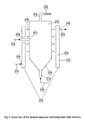
- Fig 1 there is shown a schematic of a typical fluidized bed deposition reactor comprising a containment vessel or liner, 111 , of a height, 144 , a gas introduction means, 112 , an optional gas distribution means, 113 , a bottom product removal means, 114 , a bed heating means, 115 , a gas/dust mixture exit, 116 , a connecting means, 127 , a dust/gas separation means, 117 , a dust removal means, 118 , and a gas exit, 119 .
- the containment vessel, 111 surrounds a bed of granules, 120 , fluidized by gas bubbles, 121 , and having an average top level, 122 , above which product granules, 123 , thrown up above the bed describe arcs as they rise from random impact within the bed then fall under gravity in a reduced disengaging space, 124 , while the small entrained dust particles, 125 , continue up and leave with the effluent gas, 126 , through the gas/dust mixture exit, 116 , through the connecting means, 127 , then enter the dust/gas separation means, 117 , where most of the dust, 125 , is removed from the gas, 126 , and then ultimately leaves the system via the dust removal means, 118 , while the gas, 126 , and residual dust leaves via an exit, 119 .
- the differential pressure meter, 128 measures the difference in pressure between the bottom product removal means, 114 , and the gas exit, 119 . This measurement indicates the level, 122 , of the bed of granules, 120 .
- the bottom removal means, 114 is used to control the top level, 122 , to maintain the disengaging space, 124 , so that the product granules, 123 , are returned to the bed of granules, 120 , and are thus removed by the bottom product removal means, 114 .
- Fig 2a shows a schematic similar to Fig 1 but modified to remove the granular product from the top via a gas/granular separator means, 230 , inserted before the effluent gas enters the gas/dust separation means, 217 .
- a further modification is the removal of the differential pressure transmitter, 128 , shown in Fig 1 , which is not required for bed level control.
- the invention thus comprises a containment vessel or liner, 211 , of a height, 244 , a gas introduction means, 212 , an optional gas distribution means, 213 , an optional bottom product removal means, 214 , a bed heating means, 215 , a gas/dust/granular mixture exit, 216 , a first connecting means, 241 , a gas/granular separator means, 230 , with a granular removal means, 231 , an optional heat recovery means, 242 , a further connecting means, 229 , a gas/dust separation means, 217 , a further optional heat recovery means, 243 , a dust removal means, 218 , and a gas exit, 219 .
- the containment vessel, 211 surrounds a bed of granules, 220 , fluidized by gas bubbles, 221 , and slugs, 240 , and having an average top level, 222 , above which some granules, 223 , thrown up above the bed describe arcs as they rise from random impact within the bed then fall under gravity in a reduced disengaging space, 224 , while some granules, 236 , and the small entrained dust particles, 225 , continue up and leave with the effluent gas, 233 , through the gas/dust/granular mixture exit, 216 , the connecting means, 241 , and into the gas/granular separator means, 230 , where the granules are removed via the granular removal means, 231 .
- the average top level, 222 is very close to the gas/dust/granular mixture exit, 216 , and consequently some of the product granules, 236 , thrown up above the bed do not describe arcs as they rise then fall under gravity in the disengaging space, 224 , but continue with the entrained dust, 225 , out the gas/dust/granular mixture exit, 216 . Since the average bed level, 222 , is closer to the exit, 216 , the bed level, 222 , can be taller and/or the overall height, 244 , can be shorter compared to the prior art as shown in Fig 1 .
- Fig 2b there is shown in detail the various mechanisms which cause the product granules, 236 , to be carrried out the gas exit, 216 .
- the basic mechanism is the random ejection of product granules, 236 , from the top of the bed, 222 , and the pneumatic conveying of these granules out the gas/dust/granular exit, 216 .
- the bed level oscillates up and down due to the formation of gas slugs, 240 , which lift sections of the bed up to the high level, 232 , until they break through and the bed level recedes to the low level, 234 . It is also possible for the bed to reach extra high levels, 235 , where the bed is above the exit briefly.
- the exit tube, 241 can be attached to the exit, 216 , at 90° as shown or sloped above or below the horizontal. The angle chosen can be determined by the application of standard pneumatic conveying calculations using the gas velocity in the exit tube, 241 .
- Fig 3 there is shown a more detailed schematic of a product separator, 330 , with an integrated heat recovery system, 301 , suitable for high temperature and high purity applications.
- the gas/dust/granular mixture, 333 enters the product separator, 330 , through an inlet, 357 , which goes through the heat recovery,system, 301 , via a penetration, 358 ; the gas and dust, 356 , then separate to the top and exit via the exit tube, 329 , while the granules, 336 , separate to the bottom exit, 331 , where it is fluidized by a purge stream, 359 , and withdrawn as needed.
- the heat recovery system, 301 is comprised of a heat transfer fluid, 360 , contained in a container, 351 , which is shaped to capture heat, 350 , from the wall of the product separator and has an inlet, 354 , and an outlet, 355 , for the heat transfer fluid, 360 .
- the container can use various heat transfer fluids such as water or hot oil. It is usually advantageous for the container to be a pressure vessel to permit heat recovery at higher temperatures.
- the heat may be transferred from the wall to the container by radiation, conduction or convection and well-known heat transfer techniques can be used to enhance the heat transfer from the gas and solids to the wall. Similarly, well-known gas-solids removal techniques, such as cyclones or filters, can be used to enhance the gas-solids separation.
- the heat is transferred by radiation from the hot surface of the product separator to a pressurized container which has water, 352 , coming in through the inlet, 354 , and steam, 353 , leaving through the exit, 355 .
- Fig 2 An example using Fig 2 would be as follows.
- the diameter of the container is 300 mm
- the overall height of the liner, 244 is 7 meters
- the average bed level, 222 is 6 meters
- the high level is about 6.6 meters
- the low level is about 5.4 meters.
- the gas superficial velocity at the top of the container is 4.7 ft/s (1.4 m/s).
- the average particle size of the granules is 1mm and the terminal velocity is 21.8 ft/s (6.56 m/s).
- the particle terminal velocity is thus about 4 times the superficial gas velocity. This means that in order to carry the granules out of the reactor, the local velocity in areas just above the bed must have local surges where it is 4 times higher than average.
- Velocity surges of this magnitude occur close to the top of the bed at about 20 cm above the bed.
- the slug, 240 has a maximum length of about 1.2 meter, and so the periodic growth and bursting of the slug provides the variation in height of 1.2 meters between low and high level. As the slug bursts, it also accelerates the granular particles which are then entrained out of the reactor. Thus the granular removal varies with the pulsing of the slugs, 240
- the granules and gas at the bottom of the reactor are at 700 °C, then are heated up and leave the reactor as stream, 233 , via exit, 216 , at a temperature of 800 °C. They enter the cyclonic product separator, 230 , through a tangential inlet which forces the gas and solids to the wall of the vessel to improve gas to wall heat transfer.
- the diameter of the cyclone is 10 inches (250 mm) and the length is 6 ft (1.8m). This is longer than needed for solely the solids removal in order to provide sufficient surface area for heat transfer.
- the gas and granules both leave at 600 °C.
- the dust/gas separator, 217 is of a similar size but only removes about half the heat because of the reduction in the temperature difference. The gas and dust then leave the dust/gas separator at 500 °C. Both heat recovery systems recover the heat as 150 psig steam, which is a standard utility useful in the facility for a variety of purposes and thus always in demand.
Landscapes
- Chemical & Material Sciences (AREA)
- Engineering & Computer Science (AREA)
- Organic Chemistry (AREA)
- Chemical Kinetics & Catalysis (AREA)
- Mechanical Engineering (AREA)
- General Engineering & Computer Science (AREA)
- Combustion & Propulsion (AREA)
- Environmental & Geological Engineering (AREA)
- Dispersion Chemistry (AREA)
- Devices And Processes Conducted In The Presence Of Fluids And Solid Particles (AREA)
- Cyclones (AREA)
- Silicon Compounds (AREA)
Claims (5)
- Procédé de fonctionnement d'un réacteur de dépôt à lit fluidisé pour l'enlèvement par le sommet de matière granulaire comprenant :prévoir un réacteur vertical généralement cylindrique d'une hauteur prédéterminée, ledit réacteur ayant au moins une entrée de gaz au fond ou près du fond de celui-ci et au moins une sortie de gaz et de solides au sommet ou près du sommet de celui-ci ;prévoir au moins un séparateur pour séparer le gaz du produit granulaire et un conduit entre la sortie de gaz et de solides et ledit au moins un séparateur ;établir une zone de réaction chauffée ;fournir un gaz de fluidisation à la zone de réaction à un débit prédéterminé ;fournir des particules granulaires à la zone de réaction pour établir le lit fluidisé désiré, lesdites particules ayant une hauteur fluidisée variable, le lit étant fluidisé pour établir un lit fluidisé bouillonnant avec un sommet d'une hauteur stable définie, un espace de dégagement étant prévu au-dessus dudit sommet, la hauteur dudit espace de dégagement n'étant pas supérieure à la distance entre le sommet défini du lit bouillonnant et la sortie de gaz et de solides du conteneur ;fournir un gaz à la zone de réaction tout en ajustant le débit du gaz de fluidisation afin qu'une majorité des particules granulaires soient retenues dans le réacteur tout en maintenant le bouillonnement, le gaz de réaction déposant un revêtement sur lesdites particules granulaires, accroissant ainsi la taille et le poids des particules avec pour résultat un accroissement de la hauteur du lit, etpermettre à la hauteur du lit d'augmenter et à la hauteur de dégagement de diminuer jusqu'à ce que l'éclatement de bulles près de la surface du lit expulse périodiquement des particules granulaires de la sortie de gaz et de solides du réacteur, le long du conduit et dans le séparateur de gaz et de produit granulaire,caractérisé en ce que les débits du gaz de fluidisation et du gaz de réaction sont contrôlés de manière à établir une hauteur stable du lit.
- Procédé de la revendication 1 comprenant en outre une récupération de chaleur pendant la séparation du produit granulaire du gaz, comprenant :utiliser un ou plusieurs séparateurs de produit en combinaison avec un ou plusieurs systèmes de récupération de chaleur.
- Procédé de la revendication 1 dans lequel au moins un moyen pour un enlèvement de produit granulaire est également prévu au fond du réacteur.
- Procédé de la revendication 2 dans lequel au moins un des moyens de récupération de chaleur est par rayonnement vers une chaudière à récupération de chaleur.
- Procédé de la revendication 2 dans lequel au moins un séparateur fournit un ou plusieurs courants de produit comprenant des particules de taille de particule moyenne différente.
Applications Claiming Priority (2)
| Application Number | Priority Date | Filing Date | Title |
|---|---|---|---|
| US11/810,422 US20080299015A1 (en) | 2007-06-04 | 2007-06-04 | Apparatus and method for top removal of granular material from a fluidized bed deposition reactor |
| PCT/US2008/008569 WO2008150552A2 (fr) | 2007-06-04 | 2008-07-10 | Appareil et procédé pour un enlèvement par le dessus de matière granulaire depuis un réacteur de dépôt à lit fluidisé |
Publications (3)
| Publication Number | Publication Date |
|---|---|
| EP2167227A2 EP2167227A2 (fr) | 2010-03-31 |
| EP2167227A4 EP2167227A4 (fr) | 2012-10-10 |
| EP2167227B1 true EP2167227B1 (fr) | 2016-03-02 |
Family
ID=40088456
Family Applications (1)
| Application Number | Title | Priority Date | Filing Date |
|---|---|---|---|
| EP08780156.9A Not-in-force EP2167227B1 (fr) | 2007-06-04 | 2008-07-10 | Appareil et procédé pour un enlèvement par le dessus de matière granulaire depuis un réacteur de dépôt à lit fluidisé |
Country Status (8)
| Country | Link |
|---|---|
| US (2) | US20080299015A1 (fr) |
| EP (1) | EP2167227B1 (fr) |
| JP (1) | JP2011527625A (fr) |
| KR (1) | KR101534879B1 (fr) |
| CN (1) | CN101743057B (fr) |
| AU (1) | AU2008260467B2 (fr) |
| TW (1) | TWI387484B (fr) |
| WO (1) | WO2008150552A2 (fr) |
Families Citing this family (5)
| Publication number | Priority date | Publication date | Assignee | Title |
|---|---|---|---|---|
| CN101676203B (zh) | 2008-09-16 | 2015-06-10 | 储晞 | 生产高纯颗粒硅的方法 |
| KR101678661B1 (ko) * | 2009-11-18 | 2016-11-22 | 알이씨 실리콘 인코포레이티드 | 유동층 반응기 |
| US8875728B2 (en) | 2012-07-12 | 2014-11-04 | Siliken Chemicals, S.L. | Cooled gas distribution plate, thermal bridge breaking system, and related methods |
| JP2014205145A (ja) * | 2014-06-23 | 2014-10-30 | ロード・リミテッド・エルピー | 流動床析出からの粒状微細物質の上方取り出しのための器械と方法 |
| US9404177B2 (en) * | 2014-08-18 | 2016-08-02 | Rec Silicon Inc | Obstructing member for a fluidized bed reactor |
Family Cites Families (17)
| Publication number | Priority date | Publication date | Assignee | Title |
|---|---|---|---|---|
| US3012861A (en) * | 1960-01-15 | 1961-12-12 | Du Pont | Production of silicon |
| US4642227A (en) * | 1982-08-20 | 1987-02-10 | California Institute Of Technology | Reactor for producing large particles of materials from gases |
| JPS616112A (ja) * | 1984-06-20 | 1986-01-11 | Kawasaki Steel Corp | 金属珪素の製造法 |
| JPH0755810B2 (ja) * | 1987-03-14 | 1995-06-14 | 三井東圧化学株式会社 | 高純度粒状珪素とその製造方法 |
| JPH01239013A (ja) * | 1988-03-22 | 1989-09-25 | Nkk Corp | 多結晶シリコンの製造方法及び装置 |
| US5339774A (en) * | 1993-07-06 | 1994-08-23 | Foster Wheeler Energy Corporation | Fluidized bed steam generation system and method of using recycled flue gases to assist in passing loopseal solids |
| US5560762A (en) * | 1994-03-24 | 1996-10-01 | Metallgesellschaft Ag | Process for the heat treatment of fine-grained iron ore and for the conversion of the heat treated iron ore to metallic iron |
| US5810934A (en) * | 1995-06-07 | 1998-09-22 | Advanced Silicon Materials, Inc. | Silicon deposition reactor apparatus |
| US5876793A (en) * | 1996-02-21 | 1999-03-02 | Ultramet | Fine powders and method for manufacturing |
| JP2001090926A (ja) * | 1999-09-20 | 2001-04-03 | Kawasaki Heavy Ind Ltd | ごみガス化溶融装置におけるダイオキシン類の低減方法及び装置 |
| US6451277B1 (en) * | 2000-06-06 | 2002-09-17 | Stephen M Lord | Method of improving the efficiency of a silicon purification process |
| JP2002018324A (ja) * | 2000-07-10 | 2002-01-22 | Babcock Hitachi Kk | 温度調整機構を備えたdcサイクロンセパレータ |
| US6827786B2 (en) * | 2000-12-26 | 2004-12-07 | Stephen M Lord | Machine for production of granular silicon |
| DE10124848A1 (de) * | 2001-05-22 | 2002-11-28 | Solarworld Ag | Verfahren zur Herstellung von hochreinem, granularem Silizium in einer Wirbelschicht |
| DE10260733B4 (de) * | 2002-12-23 | 2010-08-12 | Outokumpu Oyj | Verfahren und Anlage zur Wärmebehandlung von eisenoxidhaltigen Feststoffen |
| JP2005147586A (ja) * | 2003-11-18 | 2005-06-09 | Ishikawajima Harima Heavy Ind Co Ltd | 外部循環流動層ボイラ |
| DE102005039118A1 (de) * | 2005-08-18 | 2007-02-22 | Wacker Chemie Ag | Verfahren und Vorrichtung zum Zerkleinern von Silicium |
-
2007
- 2007-06-04 US US11/810,422 patent/US20080299015A1/en not_active Abandoned
-
2008
- 2008-07-10 AU AU2008260467A patent/AU2008260467B2/en not_active Ceased
- 2008-07-10 CN CN200880018753.8A patent/CN101743057B/zh not_active Expired - Fee Related
- 2008-07-10 KR KR1020107000046A patent/KR101534879B1/ko not_active IP Right Cessation
- 2008-07-10 WO PCT/US2008/008569 patent/WO2008150552A2/fr active Application Filing
- 2008-07-10 EP EP08780156.9A patent/EP2167227B1/fr not_active Not-in-force
- 2008-07-10 JP JP2010511225A patent/JP2011527625A/ja active Pending
- 2008-11-10 TW TW097143379A patent/TWI387484B/zh not_active IP Right Cessation
-
2009
- 2009-12-24 US US12/647,283 patent/US8703087B2/en not_active Expired - Fee Related
Also Published As
| Publication number | Publication date |
|---|---|
| JP2011527625A (ja) | 2011-11-04 |
| CN101743057A (zh) | 2010-06-16 |
| US20080299015A1 (en) | 2008-12-04 |
| AU2008260467A1 (en) | 2008-12-11 |
| WO2008150552A3 (fr) | 2009-03-12 |
| WO2008150552A8 (fr) | 2010-01-14 |
| TWI387484B (zh) | 2013-03-01 |
| CN101743057B (zh) | 2014-01-01 |
| EP2167227A4 (fr) | 2012-10-10 |
| EP2167227A2 (fr) | 2010-03-31 |
| KR101534879B1 (ko) | 2015-07-07 |
| AU2008260467B2 (en) | 2012-07-19 |
| TW201018526A (en) | 2010-05-16 |
| KR20110031270A (ko) | 2011-03-25 |
| US20100098850A1 (en) | 2010-04-22 |
| WO2008150552A2 (fr) | 2008-12-11 |
| US8703087B2 (en) | 2014-04-22 |
Similar Documents
| Publication | Publication Date | Title |
|---|---|---|
| EP2167227B1 (fr) | Appareil et procédé pour un enlèvement par le dessus de matière granulaire depuis un réacteur de dépôt à lit fluidisé | |
| EP0023769B1 (fr) | Appareil et procédé pour la séparation de particules solides d'un courant de mélange gaz-solides en phase mixte | |
| AU703905B2 (en) | Apparatus and method for the separation and stripping of fluid catalyst cracking particles from gaseous hydrocarbons | |
| EP1362069B1 (fr) | Processus utilisant un mode de condensation dans des lits fluidises, avec un enrichissement en phase liquide et injection des lits | |
| US6923940B2 (en) | Riser termination device | |
| US4756886A (en) | Rough cut solids separator | |
| US4220518A (en) | Method for preventing coking in fluidized bed reactor for cracking heavy hydrocarbon oil | |
| CN109715285A (zh) | 用于合成三氯硅烷的流化床反应器 | |
| US20100187158A1 (en) | Fcc separator without a reactor | |
| CN104602803B (zh) | 用于流化床反应器的改进的内部旋风分离器 | |
| EP1428570B1 (fr) | Procédé d'extraction de particules solides d'un lit fluidisé | |
| US20090107336A1 (en) | Stripping process | |
| US5037617A (en) | Apparatus for the return of particulate solids through a cyclone separator to a vessel | |
| CA3027702A1 (fr) | Elements de systeme de systemes de reacteur catalytique fluidise | |
| JP2014205145A (ja) | 流動床析出からの粒状微細物質の上方取り出しのための器械と方法 | |
| US8702972B2 (en) | Separation process | |
| CA2589583C (fr) | Entree de colonne montante permettant d'accroitre la circulation de matieres solides en particules dans des processus petrochimiques et analogues | |
| RU2174145C2 (ru) | Устройство для транспортировки дискретного материала и способ каталитического риформинга (варианты) | |
| AU6223180A (en) | Low residence time solid-gas separation device and system |
Legal Events
| Date | Code | Title | Description |
|---|---|---|---|
| PUAI | Public reference made under article 153(3) epc to a published international application that has entered the european phase |
Free format text: ORIGINAL CODE: 0009012 |
|
| 17P | Request for examination filed |
Effective date: 20091221 |
|
| AK | Designated contracting states |
Kind code of ref document: A2 Designated state(s): AT BE BG CH CY CZ DE DK EE ES FI FR GB GR HR HU IE IS IT LI LT LU LV MC MT NL NO PL PT RO SE SI SK TR |
|
| AX | Request for extension of the european patent |
Extension state: AL BA MK RS |
|
| RAP1 | Party data changed (applicant data changed or rights of an application transferred) |
Owner name: LORD LTD LP |
|
| RIN1 | Information on inventor provided before grant (corrected) |
Inventor name: STEPHEN M. LORD |
|
| REG | Reference to a national code |
Ref country code: HK Ref legal event code: DE Ref document number: 1140981 Country of ref document: HK |
|
| DAX | Request for extension of the european patent (deleted) | ||
| A4 | Supplementary search report drawn up and despatched |
Effective date: 20120906 |
|
| RIC1 | Information provided on ipc code assigned before grant |
Ipc: F27D 17/00 20060101ALI20120831BHEP Ipc: B01J 8/18 20060101AFI20120831BHEP Ipc: F27B 15/09 20060101ALI20120831BHEP Ipc: C01B 33/12 20060101ALI20120831BHEP |
|
| 17Q | First examination report despatched |
Effective date: 20130719 |
|
| GRAP | Despatch of communication of intention to grant a patent |
Free format text: ORIGINAL CODE: EPIDOSNIGR1 |
|
| INTG | Intention to grant announced |
Effective date: 20150915 |
|
| GRAS | Grant fee paid |
Free format text: ORIGINAL CODE: EPIDOSNIGR3 |
|
| GRAA | (expected) grant |
Free format text: ORIGINAL CODE: 0009210 |
|
| AK | Designated contracting states |
Kind code of ref document: B1 Designated state(s): AT BE BG CH CY CZ DE DK EE ES FI FR GB GR HR HU IE IS IT LI LT LU LV MC MT NL NO PL PT RO SE SI SK TR |
|
| REG | Reference to a national code |
Ref country code: GB Ref legal event code: FG4D |
|
| REG | Reference to a national code |
Ref country code: AT Ref legal event code: REF Ref document number: 777612 Country of ref document: AT Kind code of ref document: T Effective date: 20160315 Ref country code: CH Ref legal event code: EP |
|
| REG | Reference to a national code |
Ref country code: IE Ref legal event code: FG4D |
|
| REG | Reference to a national code |
Ref country code: DE Ref legal event code: R096 Ref document number: 602008042592 Country of ref document: DE |
|
| REG | Reference to a national code |
Ref country code: NL Ref legal event code: MP Effective date: 20160302 |
|
| REG | Reference to a national code |
Ref country code: LT Ref legal event code: MG4D |
|
| REG | Reference to a national code |
Ref country code: AT Ref legal event code: MK05 Ref document number: 777612 Country of ref document: AT Kind code of ref document: T Effective date: 20160302 |
|
| PG25 | Lapsed in a contracting state [announced via postgrant information from national office to epo] |
Ref country code: ES Free format text: LAPSE BECAUSE OF FAILURE TO SUBMIT A TRANSLATION OF THE DESCRIPTION OR TO PAY THE FEE WITHIN THE PRESCRIBED TIME-LIMIT Effective date: 20160302 Ref country code: GR Free format text: LAPSE BECAUSE OF FAILURE TO SUBMIT A TRANSLATION OF THE DESCRIPTION OR TO PAY THE FEE WITHIN THE PRESCRIBED TIME-LIMIT Effective date: 20160603 Ref country code: NO Free format text: LAPSE BECAUSE OF FAILURE TO SUBMIT A TRANSLATION OF THE DESCRIPTION OR TO PAY THE FEE WITHIN THE PRESCRIBED TIME-LIMIT Effective date: 20160602 Ref country code: FI Free format text: LAPSE BECAUSE OF FAILURE TO SUBMIT A TRANSLATION OF THE DESCRIPTION OR TO PAY THE FEE WITHIN THE PRESCRIBED TIME-LIMIT Effective date: 20160302 Ref country code: HR Free format text: LAPSE BECAUSE OF FAILURE TO SUBMIT A TRANSLATION OF THE DESCRIPTION OR TO PAY THE FEE WITHIN THE PRESCRIBED TIME-LIMIT Effective date: 20160302 |
|
| REG | Reference to a national code |
Ref country code: FR Ref legal event code: PLFP Year of fee payment: 9 |
|
| PG25 | Lapsed in a contracting state [announced via postgrant information from national office to epo] |
Ref country code: SE Free format text: LAPSE BECAUSE OF FAILURE TO SUBMIT A TRANSLATION OF THE DESCRIPTION OR TO PAY THE FEE WITHIN THE PRESCRIBED TIME-LIMIT Effective date: 20160302 Ref country code: AT Free format text: LAPSE BECAUSE OF FAILURE TO SUBMIT A TRANSLATION OF THE DESCRIPTION OR TO PAY THE FEE WITHIN THE PRESCRIBED TIME-LIMIT Effective date: 20160302 Ref country code: NL Free format text: LAPSE BECAUSE OF FAILURE TO SUBMIT A TRANSLATION OF THE DESCRIPTION OR TO PAY THE FEE WITHIN THE PRESCRIBED TIME-LIMIT Effective date: 20160302 Ref country code: LT Free format text: LAPSE BECAUSE OF FAILURE TO SUBMIT A TRANSLATION OF THE DESCRIPTION OR TO PAY THE FEE WITHIN THE PRESCRIBED TIME-LIMIT Effective date: 20160302 Ref country code: PL Free format text: LAPSE BECAUSE OF FAILURE TO SUBMIT A TRANSLATION OF THE DESCRIPTION OR TO PAY THE FEE WITHIN THE PRESCRIBED TIME-LIMIT Effective date: 20160302 Ref country code: LV Free format text: LAPSE BECAUSE OF FAILURE TO SUBMIT A TRANSLATION OF THE DESCRIPTION OR TO PAY THE FEE WITHIN THE PRESCRIBED TIME-LIMIT Effective date: 20160302 |
|
| PG25 | Lapsed in a contracting state [announced via postgrant information from national office to epo] |
Ref country code: IS Free format text: LAPSE BECAUSE OF FAILURE TO SUBMIT A TRANSLATION OF THE DESCRIPTION OR TO PAY THE FEE WITHIN THE PRESCRIBED TIME-LIMIT Effective date: 20160702 Ref country code: EE Free format text: LAPSE BECAUSE OF FAILURE TO SUBMIT A TRANSLATION OF THE DESCRIPTION OR TO PAY THE FEE WITHIN THE PRESCRIBED TIME-LIMIT Effective date: 20160302 |
|
| PG25 | Lapsed in a contracting state [announced via postgrant information from national office to epo] |
Ref country code: SK Free format text: LAPSE BECAUSE OF FAILURE TO SUBMIT A TRANSLATION OF THE DESCRIPTION OR TO PAY THE FEE WITHIN THE PRESCRIBED TIME-LIMIT Effective date: 20160302 Ref country code: PT Free format text: LAPSE BECAUSE OF FAILURE TO SUBMIT A TRANSLATION OF THE DESCRIPTION OR TO PAY THE FEE WITHIN THE PRESCRIBED TIME-LIMIT Effective date: 20160704 Ref country code: CZ Free format text: LAPSE BECAUSE OF FAILURE TO SUBMIT A TRANSLATION OF THE DESCRIPTION OR TO PAY THE FEE WITHIN THE PRESCRIBED TIME-LIMIT Effective date: 20160302 Ref country code: RO Free format text: LAPSE BECAUSE OF FAILURE TO SUBMIT A TRANSLATION OF THE DESCRIPTION OR TO PAY THE FEE WITHIN THE PRESCRIBED TIME-LIMIT Effective date: 20160302 |
|
| REG | Reference to a national code |
Ref country code: DE Ref legal event code: R097 Ref document number: 602008042592 Country of ref document: DE |
|
| PG25 | Lapsed in a contracting state [announced via postgrant information from national office to epo] |
Ref country code: IT Free format text: LAPSE BECAUSE OF FAILURE TO SUBMIT A TRANSLATION OF THE DESCRIPTION OR TO PAY THE FEE WITHIN THE PRESCRIBED TIME-LIMIT Effective date: 20160302 Ref country code: BE Free format text: LAPSE BECAUSE OF FAILURE TO SUBMIT A TRANSLATION OF THE DESCRIPTION OR TO PAY THE FEE WITHIN THE PRESCRIBED TIME-LIMIT Effective date: 20160302 |
|
| PLBE | No opposition filed within time limit |
Free format text: ORIGINAL CODE: 0009261 |
|
| STAA | Information on the status of an ep patent application or granted ep patent |
Free format text: STATUS: NO OPPOSITION FILED WITHIN TIME LIMIT |
|
| PG25 | Lapsed in a contracting state [announced via postgrant information from national office to epo] |
Ref country code: DK Free format text: LAPSE BECAUSE OF FAILURE TO SUBMIT A TRANSLATION OF THE DESCRIPTION OR TO PAY THE FEE WITHIN THE PRESCRIBED TIME-LIMIT Effective date: 20160302 |
|
| 26N | No opposition filed |
Effective date: 20161205 |
|
| PG25 | Lapsed in a contracting state [announced via postgrant information from national office to epo] |
Ref country code: SI Free format text: LAPSE BECAUSE OF FAILURE TO SUBMIT A TRANSLATION OF THE DESCRIPTION OR TO PAY THE FEE WITHIN THE PRESCRIBED TIME-LIMIT Effective date: 20160302 Ref country code: BG Free format text: LAPSE BECAUSE OF FAILURE TO SUBMIT A TRANSLATION OF THE DESCRIPTION OR TO PAY THE FEE WITHIN THE PRESCRIBED TIME-LIMIT Effective date: 20160602 |
|
| REG | Reference to a national code |
Ref country code: CH Ref legal event code: PL |
|
| PG25 | Lapsed in a contracting state [announced via postgrant information from national office to epo] |
Ref country code: MC Free format text: LAPSE BECAUSE OF FAILURE TO SUBMIT A TRANSLATION OF THE DESCRIPTION OR TO PAY THE FEE WITHIN THE PRESCRIBED TIME-LIMIT Effective date: 20160302 |
|
| PG25 | Lapsed in a contracting state [announced via postgrant information from national office to epo] |
Ref country code: CH Free format text: LAPSE BECAUSE OF NON-PAYMENT OF DUE FEES Effective date: 20160731 Ref country code: LI Free format text: LAPSE BECAUSE OF NON-PAYMENT OF DUE FEES Effective date: 20160731 |
|
| REG | Reference to a national code |
Ref country code: IE Ref legal event code: MM4A |
|
| REG | Reference to a national code |
Ref country code: FR Ref legal event code: PLFP Year of fee payment: 10 |
|
| PG25 | Lapsed in a contracting state [announced via postgrant information from national office to epo] |
Ref country code: IE Free format text: LAPSE BECAUSE OF NON-PAYMENT OF DUE FEES Effective date: 20160710 |
|
| PG25 | Lapsed in a contracting state [announced via postgrant information from national office to epo] |
Ref country code: LU Free format text: LAPSE BECAUSE OF NON-PAYMENT OF DUE FEES Effective date: 20160710 |
|
| PGFP | Annual fee paid to national office [announced via postgrant information from national office to epo] |
Ref country code: FR Payment date: 20170724 Year of fee payment: 10 Ref country code: GB Payment date: 20170719 Year of fee payment: 10 Ref country code: DE Payment date: 20170724 Year of fee payment: 10 |
|
| REG | Reference to a national code |
Ref country code: HK Ref legal event code: WD Ref document number: 1140981 Country of ref document: HK |
|
| PG25 | Lapsed in a contracting state [announced via postgrant information from national office to epo] |
Ref country code: HU Free format text: LAPSE BECAUSE OF FAILURE TO SUBMIT A TRANSLATION OF THE DESCRIPTION OR TO PAY THE FEE WITHIN THE PRESCRIBED TIME-LIMIT; INVALID AB INITIO Effective date: 20080710 Ref country code: CY Free format text: LAPSE BECAUSE OF FAILURE TO SUBMIT A TRANSLATION OF THE DESCRIPTION OR TO PAY THE FEE WITHIN THE PRESCRIBED TIME-LIMIT Effective date: 20160302 |
|
| PG25 | Lapsed in a contracting state [announced via postgrant information from national office to epo] |
Ref country code: TR Free format text: LAPSE BECAUSE OF FAILURE TO SUBMIT A TRANSLATION OF THE DESCRIPTION OR TO PAY THE FEE WITHIN THE PRESCRIBED TIME-LIMIT Effective date: 20160302 Ref country code: MT Free format text: LAPSE BECAUSE OF NON-PAYMENT OF DUE FEES Effective date: 20160731 |
|
| REG | Reference to a national code |
Ref country code: DE Ref legal event code: R119 Ref document number: 602008042592 Country of ref document: DE |
|
| GBPC | Gb: european patent ceased through non-payment of renewal fee |
Effective date: 20180710 |
|
| PG25 | Lapsed in a contracting state [announced via postgrant information from national office to epo] |
Ref country code: DE Free format text: LAPSE BECAUSE OF NON-PAYMENT OF DUE FEES Effective date: 20190201 Ref country code: FR Free format text: LAPSE BECAUSE OF NON-PAYMENT OF DUE FEES Effective date: 20180731 Ref country code: GB Free format text: LAPSE BECAUSE OF NON-PAYMENT OF DUE FEES Effective date: 20180710 |