EP2164775B1 - Ventil und abgabevorrichtung - Google Patents
Ventil und abgabevorrichtung Download PDFInfo
- Publication number
- EP2164775B1 EP2164775B1 EP08762210.6A EP08762210A EP2164775B1 EP 2164775 B1 EP2164775 B1 EP 2164775B1 EP 08762210 A EP08762210 A EP 08762210A EP 2164775 B1 EP2164775 B1 EP 2164775B1
- Authority
- EP
- European Patent Office
- Prior art keywords
- valve
- outlet
- container
- inlet
- pressure
- Prior art date
- Legal status (The legal status is an assumption and is not a legal conclusion. Google has not performed a legal analysis and makes no representation as to the accuracy of the status listed.)
- Not-in-force
Links
- 239000012530 fluid Substances 0.000 claims description 29
- 239000007788 liquid Substances 0.000 claims description 17
- 239000006260 foam Substances 0.000 claims description 3
- 239000007921 spray Substances 0.000 claims description 3
- 230000001419 dependent effect Effects 0.000 claims 1
- IJGRMHOSHXDMSA-UHFFFAOYSA-N Atomic nitrogen Chemical compound N#N IJGRMHOSHXDMSA-UHFFFAOYSA-N 0.000 description 10
- CURLTUGMZLYLDI-UHFFFAOYSA-N Carbon dioxide Chemical compound O=C=O CURLTUGMZLYLDI-UHFFFAOYSA-N 0.000 description 10
- 239000000443 aerosol Substances 0.000 description 9
- 239000007789 gas Substances 0.000 description 8
- 239000003380 propellant Substances 0.000 description 8
- 239000001569 carbon dioxide Substances 0.000 description 5
- 229910002092 carbon dioxide Inorganic materials 0.000 description 5
- JCXJVPUVTGWSNB-UHFFFAOYSA-N nitrogen dioxide Inorganic materials O=[N]=O JCXJVPUVTGWSNB-UHFFFAOYSA-N 0.000 description 4
- 229910052757 nitrogen Inorganic materials 0.000 description 3
- ATUOYWHBWRKTHZ-UHFFFAOYSA-N Propane Chemical compound CCC ATUOYWHBWRKTHZ-UHFFFAOYSA-N 0.000 description 2
- NNPPMTNAJDCUHE-UHFFFAOYSA-N isobutane Chemical compound CC(C)C NNPPMTNAJDCUHE-UHFFFAOYSA-N 0.000 description 2
- 230000007246 mechanism Effects 0.000 description 2
- 238000009835 boiling Methods 0.000 description 1
- 239000001273 butane Substances 0.000 description 1
- 235000019504 cigarettes Nutrition 0.000 description 1
- 238000010276 construction Methods 0.000 description 1
- 230000000254 damaging effect Effects 0.000 description 1
- 230000007423 decrease Effects 0.000 description 1
- 239000001282 iso-butane Substances 0.000 description 1
- 235000013847 iso-butane Nutrition 0.000 description 1
- 238000004519 manufacturing process Methods 0.000 description 1
- 239000003595 mist Substances 0.000 description 1
- IJDNQMDRQITEOD-UHFFFAOYSA-N n-butane Chemical compound CCCC IJDNQMDRQITEOD-UHFFFAOYSA-N 0.000 description 1
- OFBQJSOFQDEBGM-UHFFFAOYSA-N n-pentane Natural products CCCCC OFBQJSOFQDEBGM-UHFFFAOYSA-N 0.000 description 1
- 239000001294 propane Substances 0.000 description 1
- 238000007789 sealing Methods 0.000 description 1
- 239000007787 solid Substances 0.000 description 1
- 231100000331 toxic Toxicity 0.000 description 1
- 230000002588 toxic effect Effects 0.000 description 1
- 238000013022 venting Methods 0.000 description 1
- 239000012855 volatile organic compound Substances 0.000 description 1
- 239000002699 waste material Substances 0.000 description 1
Images


Classifications
-
- B—PERFORMING OPERATIONS; TRANSPORTING
- B65—CONVEYING; PACKING; STORING; HANDLING THIN OR FILAMENTARY MATERIAL
- B65D—CONTAINERS FOR STORAGE OR TRANSPORT OF ARTICLES OR MATERIALS, e.g. BAGS, BARRELS, BOTTLES, BOXES, CANS, CARTONS, CRATES, DRUMS, JARS, TANKS, HOPPERS, FORWARDING CONTAINERS; ACCESSORIES, CLOSURES, OR FITTINGS THEREFOR; PACKAGING ELEMENTS; PACKAGES
- B65D83/00—Containers or packages with special means for dispensing contents
- B65D83/14—Containers or packages with special means for dispensing contents for delivery of liquid or semi-liquid contents by internal gaseous pressure, i.e. aerosol containers comprising propellant for a product delivered by a propellant
-
- B—PERFORMING OPERATIONS; TRANSPORTING
- B67—OPENING, CLOSING OR CLEANING BOTTLES, JARS OR SIMILAR CONTAINERS; LIQUID HANDLING
- B67D—DISPENSING, DELIVERING OR TRANSFERRING LIQUIDS, NOT OTHERWISE PROVIDED FOR
- B67D1/00—Apparatus or devices for dispensing beverages on draught
- B67D1/04—Apparatus utilising compressed air or other gas acting directly or indirectly on beverages in storage containers
-
- B—PERFORMING OPERATIONS; TRANSPORTING
- B65—CONVEYING; PACKING; STORING; HANDLING THIN OR FILAMENTARY MATERIAL
- B65D—CONTAINERS FOR STORAGE OR TRANSPORT OF ARTICLES OR MATERIALS, e.g. BAGS, BARRELS, BOTTLES, BOXES, CANS, CARTONS, CRATES, DRUMS, JARS, TANKS, HOPPERS, FORWARDING CONTAINERS; ACCESSORIES, CLOSURES, OR FITTINGS THEREFOR; PACKAGING ELEMENTS; PACKAGES
- B65D83/00—Containers or packages with special means for dispensing contents
- B65D83/14—Containers or packages with special means for dispensing contents for delivery of liquid or semi-liquid contents by internal gaseous pressure, i.e. aerosol containers comprising propellant for a product delivered by a propellant
- B65D83/42—Filling or charging means
- B65D83/425—Delivery valves permitting filling or charging
-
- B—PERFORMING OPERATIONS; TRANSPORTING
- B65—CONVEYING; PACKING; STORING; HANDLING THIN OR FILAMENTARY MATERIAL
- B65D—CONTAINERS FOR STORAGE OR TRANSPORT OF ARTICLES OR MATERIALS, e.g. BAGS, BARRELS, BOTTLES, BOXES, CANS, CARTONS, CRATES, DRUMS, JARS, TANKS, HOPPERS, FORWARDING CONTAINERS; ACCESSORIES, CLOSURES, OR FITTINGS THEREFOR; PACKAGING ELEMENTS; PACKAGES
- B65D83/00—Containers or packages with special means for dispensing contents
- B65D83/14—Containers or packages with special means for dispensing contents for delivery of liquid or semi-liquid contents by internal gaseous pressure, i.e. aerosol containers comprising propellant for a product delivered by a propellant
- B65D83/60—Contents and propellant separated
- B65D83/66—Contents and propellant separated first separated, but finally mixed, e.g. in a dispensing head
- B65D83/663—Contents and propellant separated first separated, but finally mixed, e.g. in a dispensing head at least a portion of the propellant being separated from the product and incrementally released by means of a pressure regulator
-
- B—PERFORMING OPERATIONS; TRANSPORTING
- B67—OPENING, CLOSING OR CLEANING BOTTLES, JARS OR SIMILAR CONTAINERS; LIQUID HANDLING
- B67D—DISPENSING, DELIVERING OR TRANSFERRING LIQUIDS, NOT OTHERWISE PROVIDED FOR
- B67D1/00—Apparatus or devices for dispensing beverages on draught
- B67D1/04—Apparatus utilising compressed air or other gas acting directly or indirectly on beverages in storage containers
- B67D1/0412—Apparatus utilising compressed air or other gas acting directly or indirectly on beverages in storage containers the whole dispensing unit being fixed to the container
-
- F—MECHANICAL ENGINEERING; LIGHTING; HEATING; WEAPONS; BLASTING
- F16—ENGINEERING ELEMENTS AND UNITS; GENERAL MEASURES FOR PRODUCING AND MAINTAINING EFFECTIVE FUNCTIONING OF MACHINES OR INSTALLATIONS; THERMAL INSULATION IN GENERAL
- F16K—VALVES; TAPS; COCKS; ACTUATING-FLOATS; DEVICES FOR VENTING OR AERATING
- F16K15/00—Check valves
- F16K15/02—Check valves with guided rigid valve members
- F16K15/04—Check valves with guided rigid valve members shaped as balls
-
- F—MECHANICAL ENGINEERING; LIGHTING; HEATING; WEAPONS; BLASTING
- F16—ENGINEERING ELEMENTS AND UNITS; GENERAL MEASURES FOR PRODUCING AND MAINTAINING EFFECTIVE FUNCTIONING OF MACHINES OR INSTALLATIONS; THERMAL INSULATION IN GENERAL
- F16K—VALVES; TAPS; COCKS; ACTUATING-FLOATS; DEVICES FOR VENTING OR AERATING
- F16K15/00—Check valves
- F16K15/02—Check valves with guided rigid valve members
- F16K15/06—Check valves with guided rigid valve members with guided stems
-
- Y—GENERAL TAGGING OF NEW TECHNOLOGICAL DEVELOPMENTS; GENERAL TAGGING OF CROSS-SECTIONAL TECHNOLOGIES SPANNING OVER SEVERAL SECTIONS OF THE IPC; TECHNICAL SUBJECTS COVERED BY FORMER USPC CROSS-REFERENCE ART COLLECTIONS [XRACs] AND DIGESTS
- Y10—TECHNICAL SUBJECTS COVERED BY FORMER USPC
- Y10T—TECHNICAL SUBJECTS COVERED BY FORMER US CLASSIFICATION
- Y10T137/00—Fluid handling
- Y10T137/7722—Line condition change responsive valves
- Y10T137/7837—Direct response valves [i.e., check valve type]
- Y10T137/7904—Reciprocating valves
Definitions
- This invention relates to a valve and a dispenser comprising a valve.
- DE 298 23 474 U1 relates to a valve with an inlet and an outlet, the valve having a valve element moveable between a first equilibrium position and a second open position in response to pressure at the inlet and the outlet.
- US 2006/0192168 A1 relates to a ball valve that opens when suction is applied at the top of the ball and closes once the suction is removed.
- a valve comprising an inlet and an outlet, the valve having a valve element moveable between a first equilibrium position and a second open position, wherein when the valve element is in the first position, the inlet and the outlet are not in flow communication and when the valve element is in the second position the inlet and the outlet are in flow communication, and wherein the valve element is moveable between the first position and the second position in response to the pressure at the inlet and the outlet, characterised in that the valve element comprises a piston having a first surface area responsive to pressure at the outlet and a second smaller surface area responsive to the pressure at the inlet, wherein the piston may be moveable in response to the net force on the first and second surface areas.
- the piston may be moveable in a first bore in flow communication with the outlet and the second surface area may be provided on a rod attached to the piston and moveable in a second bore in flow communication with the inlet.
- a through-bore may be provided in the rod, and an upper seal and a lower seal may be provided to provide a sliding seal between the rod and the second bore.
- an end part of the rod may be located between the upper seal and lower seal such that fluid is able to pass the lower seal, around the rod and enter the throughbore.
- the valve element may be moveable to a third position in response to the pressure at the inlet and outlet wherein the inlet and outlet are not in flow communication.
- the valve element may move between the first position and the second position solely in response to a net force from the opposing fluid pressures at the inlet and outlet and no bias element or control element may be present to move the valve element between the first and second positions.
- valve is in a dispenser for liquid, such as an aerosol.
- a dispenser for liquid such as an aerosol.
- a propellant comprising a volatile organic compound such as propane, butane or ISO-butane.
- Such propellants have such low boiling points that that when introduced to an aerosol or cigarette lighter they comfortably remain as liquids at low pressures which boil off at low temperatures as pressure decreases when the aerosol is used. It is known that these propellants are inflammable and toxic. Inert or less harmful propellants such as nitrogen or carbon dioxide have been considered. However, for nitrogen to be a liquid requires it be held captive at some 27,6 MPa (4000 psi) and carbon dioxide at 5,6 MPa (815 psi), which is too high to be contained within conventional aerosol containers.
- a dispenser comprising a container and an nozzle to release liquid under pressure from the container, the dispenser further comprising a pressure source to supply fluid under pressure to the container, the pressure source and container being connected by a valve according to the first aspect of the invention.
- the pressure source may be releasably connectable to the container.
- the pressure source may comprise the valve and a pressure bottle.
- the container may have a connection part to engage the pressure source, the connection part having a push rod to urge the valve element from the third position to the second position when a pressure source is engaged with the container.
- the nozzle is connectable to a tube extending into the container, to permit liquid to be dispensed from the container.
- the liquid may be dispensed as one of a spray, a jet or a foam.
- a valve embodying the present invention is generally shown at 10 in Figures 1 a to 1 d .
- the valve 10 is suitable for use in any suitable application where a controlled supply of fluid pressure is required .
- the valve 10 comprises an inlet 11 to which fluid under pressure is supplied.
- the pressurized fluid may be gas supplied from, for example, a gas canister.
- a piston 12 is moveable within a first bore 13, its movement being constrained in this example by an end 14 of the first bore 13 and a circlip 15.
- a second bore 16 having a smaller diameter than the first bore 13 extends from the first bore 13 to the inlet 11.
- a piston rod 17 is connected to the piston 12 and is slidably moveable within the second bore 16.
- a channel 18 extends from the upper face of the piston 12 through the piston rod 17 and has one or more ports 19.
- An upper o-ring seal 20 and a lower o-ring seal 21 supported in grooves in the second bore 16 provide a sliding seal between the piston rod 17 and the second bore 16.
- An upper part of the first bore 13 provides an outlet.
- the volume of the bore 13 between the piston 12 and the end 14 of the bore 13 is preferably at a lower pressure, for example venting to atmosphere via a suitable port (not shown).
- the piston 12 is able to move freely in response to the net force from the different pressures at the inlet 11 and the outlet acting on the larger surface area of the piston 12 and the smaller surface area of the end of the piston rod 17.
- Figure 1 a shows the valve 10 in a first, equilibrium, position, where the lower pressure at the outlet and hence in the bore 13 is balanced by the higher pressure in the inlet and applied to the smaller area of the end of the rod 17. Accordingly, there is no net force on the piston 12, or insufficient net force on the piston 12 to cause the piston to move against any frictional forces such as between the seals 20, 21 and the piston rod 17.
- valve 10 can also be used to refill a gas container.
- a refill pressure applied to the outlet 22 forces the piston 12 downwards until it reaches a fourth position, in this example when the piston engages the end 14 of the bore 13.
- the channel 18 and ports 19 provide a fluid connection allowing fluid under pressure to pass from the outlet 22 to the inlet 11.
- the piston 12 will be urged upwards until it reaches the position shown in Figure 1 c .
- a suitable physical mechanism such as a push rod can be used to move the piston 12 to the fourth position when the valve is engaged with a source of refill pressure, and permit the piston 12 to return to the third position shown in Figure 1 c when the valve 10 is disconnected from the source of refill pressure.
- the fourth position may be defined by some other stop, such as a circlip within the bore, if it is desirable for the piston 12 not necessarily to contact the end face 14.
- FIG. 2 shows an alternative piston 12' and rod 17' in which the rod 17' is solid apart from a through-bore 24, and the rod 17' is sufficiently long that it is always in sealing contact with the lower O-ring 21. Movement of the piston 12' causes the through-bore 24 to open and close a supply channel 25 to supply fluid to an outlet 22' in flow communication with the bore 13.
- valve 10 When the valve 10, 10' is connection to a device such as a dispenser which is to be supplied with pressurised fluid, it will be apparent that the piston 12 will be in the third position as shown in Figure 1 c .
- a push rod 26 is provided as part of a connector 27 on a device to which the valve 10 is attached via a threaded connection 28.
- the push rod 23 As the valve 10 is screwed onto the threaded connection 28, the push rod 23 will come into contact with the piston 12, and displace the piston 12 from the closed position of Figure 1 c allowing pressure to pass from the inlet 11 to the bore 13.
- the piston 12 Once the pressure within the device and hence at the bore 13 rises sufficiently, the piston 12 will move to the first, equilibrium position and subsequently operate as discussed above in response to changes in the pressure at the bore 13.
- valve 10 is not intended to be able to permit refilling of a pressure source, then the valve may be configured such that the piston 12 is not able to move to the fourth position as shown in Figure 1 d . This may be achieved, for example, by selecting the length of the rod 17 such that it cannot extend beyond the lower O-ring 21, or by limiting the range of travel of the piston 12 by the position of the end 14 of the bore 13, or providing a further circlip, or otherwise.
- valve 10 may be used in any suitable application, where it is desired to supply fluid under pressure from a source at a higher pressure to a device or volume at a lower pressure.
- the source may be a container holding fluid under pressure, such as a gas bottle, or a pressure line, or a pump, or any other suitable source.
- the construction of the valve is simple, without the need for biasing or control devices, and the relative dimensions of the piston 12 and rod 17 can be selected in accordance with the desired pressure of the source and the outlet pressure.
- the valve 10 is suitable for miniaturisation and simple to manufacture.
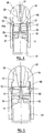
- a dispenser is shown at 30, in this example comprising an aerosol operable such that the contents of the dispenser are ejected as a mist, spray or foam, but may be any other type of dispenser as desired.
- the dispenser 30 comprises a container 31 for holding a liquid to be dispensed, closed by a cap 32 at the upper end of the container 31.
- a connection part 33 is disposed at the lower part of the container 31 to receive a source of gas pressure, as discussed in more detail below.
- the cap 32 has a nozzle 34 a and a dip tube 34 b extending into the body of the container 31.
- a button 35 is provided which, when pressed, connects the dip tube 34 b to the nozzle 34 a so that liquid is forced from the container 31 by the pressure in the container 31, through the dip tube 34 a and out through the nozzle 34 a .
- connection part 33 comprises a generally cylindrical body 36 with an internal seal 37. Vents 38 connect the connection part 33 to the interior of the container 31. A push rod 39 extends downwardly into the body to 36 to engage a valve 10 as discussed below.
- a pressure source 40 is provided.
- the pressure source 40 comprises a pressure bottle 41 and a regulator 42 which includes a valve 10 as described above, the piston 12 having a seal 12 a and being moveable in an end part 40 a of the pressure source 40.
- a threaded screw 43 provides a connection to atmosphere for the volume below the piston 12.
- the threaded screw 43 also prevents movement of the piston 12 to the fourth position as a safety measure to prevent or hinder discharge of the pressure bottle 41 when it is not in use.
- the valve 10 is in the third position as shown in Figure 1 c .
- the pressure source 40 is introduced into the connection part 33 as shown in figure 4 , by inserting the pressure source until it passes the seal 37. Pushing the pressure source in further brings the piston 12 into contact with the push rod 39. As described above, this urges the piston 12 away the third position and into the second position as shown in Figure 5 . Fluid under pressure is supplied from the valve 10 through vents 38 into the container 31. When the container 31 reaches a suitable pressure, as set by selecting the dimensions of the piston 12 and piston rod 17 as discussed above, the piston 12 will move to the first, equilibrium position as shown in Figure 6 .
- pressure source 40 and connection part 33 are shown located generally centrally of the container 31 and contained within the lower part of the container 31, a dispenser may be provided with the pressure source and container located and connected in any suitable manner.
- the threaded screw 43 is removed or sufficiently withdrawn to permit movement of the piston 12 to the fourth position.
- the valve 10 can then be engaged with a suitable refilling nozzle 44 which urges the piston 12 to the fourth position as shown in Figure 7 .
- Pressure is supplied from a channel 45 of the nozzle 44 through bore 18 and outlet 19 into the pressure bottle 41.
- the cap 32 or the connection part 33 can be removed to permit liquid to be introduced to the container 31, and then closed with a suitable liquid- and pressure-tight seal.
- suitable the liquid to be dispensed may be introduced into the container 31 through vents 38 prior to inserting the pressure source 40.
- the dispenser is advantageous in that it allows an aerosol or dispenser to be provided which is capable of being refilled with both the liquid to be dispensed and propellant. Accordingly, this provides substantial advantages over known aerosols where the entire container must be thrown away, representing a substantial waste of resources, once the contents have been discharged.
- the dispenser is also advantageous as the use of the valve 10 permits nitrogen or carbon dioxide to be reliably used. Nitrogen or carbon dioxide will not have the environmentally damaging effects of known propellants and are comparatively cheap to produce and distribute. Nitrogen and carbon dioxide are also inert, relatively inexpensive and will not have the risks associated with known flammable propellants.
- the pressure source can contain liquid nitrogen at approximately 4000 psi. The areas of the piston and the rod would be selected so that the valve element moves to its first, equilibrium position when these pressures are applied to the outlet and inlet of the valve 10 respectively. I cc of liquid nitrogen would give 696.5 cc as a gas at 70C. A pressure source with a volume of 12 cc could therefore provide propellant for approximately 10 discharges of the dispenser.
- pressure source comprising a pressure bottle and a valve 10
- a pressure bottle and a valve 10 may be used separately, for any suitable function.
Landscapes
- Engineering & Computer Science (AREA)
- Mechanical Engineering (AREA)
- Chemical & Material Sciences (AREA)
- Dispersion Chemistry (AREA)
- General Engineering & Computer Science (AREA)
- Containers And Packaging Bodies Having A Special Means To Remove Contents (AREA)
- Devices For Dispensing Beverages (AREA)
- Nozzles (AREA)
- Closures For Containers (AREA)
- Feeding And Controlling Fuel (AREA)
- Fluid-Driven Valves (AREA)
Claims (13)
- Ventil 10, umfassend einen Einlass 11 und einen Auslass 22, wobei das Ventil über ein Ventilelement verfügt, das zwischen einer ersten Gleichgewichtsstellung und einer zweiten offenen Stellung bewegbar ist, wobei Einlass und Auslass, wenn sich das Ventilelement in der ersten Stellung befindet, in keiner Strömungsverbindung stehen, und Einlass und Auslass, wenn das Ventilelement sich in der zweiten Stellung befindet, in einer Strömungsverbindung stehen, und wobei das Ventilelement umgekehrt als Reaktion auf eine resultierende Kraft aus den entgegengesetzten Flüssigkeitsdrücken am Einlass und Auslass aus der ersten Stellung in die zweite Stellung bewegt wird,
dadurch gekennzeichnet, dass
das Ventilelement einen Kolben 12 mit einem ersten Oberflächenbereich umfasst, der auf Flüssigkeitsdruck am Auslass reagiert, und einen zweiten kleineren Oberflächenbereich umfasst, der auf Flüssigkeitsdruck am Einlass reagiert, wobei der Kolben in Reaktion auf die resultierende Kraft auf den ersten und zweiten Oberflächenbereich bewegbar ist. - Ventil 10 gemäß Anspruch 1, wobei der Kolben 12 in einer ersten Bohrung 13 bewegbar ist, die in Strömungsverbindung mit dem Auslass 22 steht, und wobei der zweite Oberflächenbereich auf einer Stange 17 bereitgestellt ist, die am Kolben angebracht ist und in einer zweiten Bohrung 16 bewegbar ist, die in Strömungsverbindung mit dem Einlass 11 steht.
- Ventil 10 gemäß Anspruch 2, wobei eine Durchgangsbohrung 24 in der Stange 17 bereitgestellt ist und eine obere Dichtung und eine untere Dichtung bereitgestellt sind, um eine Gleitdichtung zwischen der Stange und der zweiten Bohrung 16 bereitzustellen.
- Ventil gemäß Anspruch 3, wobei sich in der zweiten Stellung ein Endstück der Stange 17 zwischen der oberen Dichtung 20 und der unteren Dichtung 21 befindet, sodass Flüssigkeit die untere Dichtung rund um die Stange passieren und in die Durchgangsbohrung 24 eintreten kann.
- Ventil 10 gemäß einem der vorherigen Ansprüche, wobei das Ventilelement in Reaktion auf die resultierende Kraft aus den entgegengesetzten Flüssigkeitsdrücken am Einlass 11 und am Auslass 22 in eine dritte Stellung bewegbar ist, wobei Einlass und Auslass nicht in Strömungsverbindung stehen.
- Ventil 10 gemäß einem der vorherigen Ansprüche, wobei das Ventilelement in eine vierte Stellung bewegbar ist, damit ein Flüssigkeitsstrom vom Auslass 22 zum Einlass 11 möglich ist.
- Ventil 10 gemäß einem der vorherigen Ansprüche, wobei das Ventilelement zwischen der ersten Stellung und der zweiten Stellung nur in Reaktion auf eine resultierende Kraft aus den entgegengesetzten Flüssigkeitsdrücken am Einlass 11 und am Auslass 22 bewegbar ist und kein Spannelement oder Steuerelement vorhanden ist, das das Ventilelement zwischen der ersten und der zweiten Stellung bewegt.
- Spender 30, umfassend einen Behälter 31 und eine Düse 34a zur Freisetzung von Flüssigkeit unter Druck aus dem Behälter, wobei der Spender darüber hinaus eine Druckquelle 40 zur Lieferung von Flüssigkeit unter Druck an den Behälter umfasst, wobei die Druckquelle und der Behälter über ein Ventil 10 gemäß einem der vorherigen Ansprüche verbunden sind.
- Spender 30 gemäß Anspruch 8, wobei die Druckquelle 40 lösbar mit dem Behälter 31 verbunden ist.
- Spender 30 gemäß Anspruch 9, wobei die Druckquelle 40 das Ventil 10 und eine Druckflasche 41 umfasst.
- Spender 30 gemäß Anspruch 10, soweit indirekt abhängig von Anspruch 4, wobei der Behälter 31 ein Verbindungsstück besitzt, um die Druckquelle 40 einzubeziehen, wobei das Verbindungsstück über einen Stößel 39 verfügt, um das Ventilelement aus der dritten Stellung in die zweite Stellung zu drücken, wenn eine Druckquelle mit dem Behälter in Eingriff steht.
- Spender 30 gemäß einem der Ansprüche 8 bis 11, wobei die Düse an einen Schlauch anschließbar ist, der sich in den Behälter erstreckt, damit die Flüssigkeit aus dem Behälter abgegeben werden kann.
- Spender 30 gemäß einem der Ansprüche 8 bis 12, wobei die Flüssigkeit in Form von Sprühnebel, Strahl oder Schaum abgegeben wird.
Applications Claiming Priority (2)
| Application Number | Priority Date | Filing Date | Title |
|---|---|---|---|
| PCT/GB2007/001991 WO2007138312A1 (en) | 2006-05-26 | 2007-05-29 | Liquid dispenser that uses two pressure levels |
| PCT/GB2008/001830 WO2008146001A2 (en) | 2007-05-29 | 2008-05-29 | Valve and dispenser |
Publications (2)
| Publication Number | Publication Date |
|---|---|
| EP2164775A2 EP2164775A2 (de) | 2010-03-24 |
| EP2164775B1 true EP2164775B1 (de) | 2018-07-04 |
Family
ID=40084322
Family Applications (1)
| Application Number | Title | Priority Date | Filing Date |
|---|---|---|---|
| EP08762210.6A Not-in-force EP2164775B1 (de) | 2007-05-29 | 2008-05-29 | Ventil und abgabevorrichtung |
Country Status (15)
| Country | Link |
|---|---|
| US (1) | US8556133B2 (de) |
| EP (1) | EP2164775B1 (de) |
| JP (1) | JP5368431B2 (de) |
| KR (1) | KR20100031583A (de) |
| CN (1) | CN101678946B (de) |
| AU (1) | AU2008256528B2 (de) |
| CA (1) | CA2688345A1 (de) |
| GB (2) | GB2438395B (de) |
| HK (1) | HK1135165A1 (de) |
| MX (1) | MX2009012831A (de) |
| MY (1) | MY147277A (de) |
| NZ (1) | NZ582058A (de) |
| RU (1) | RU2478544C2 (de) |
| WO (1) | WO2008146001A2 (de) |
| ZA (1) | ZA200909038B (de) |
Families Citing this family (6)
| Publication number | Priority date | Publication date | Assignee | Title |
|---|---|---|---|---|
| BE1020003A3 (nl) * | 2011-06-09 | 2013-03-05 | Cardiff Group Naamoloze Vennootschap | Een houder om een vloeibaar voedingsmiddel in te bewaren en onder druk uit te verdelen. |
| CN106999880B (zh) * | 2014-10-28 | 2020-07-14 | 卢卡·德罗科 | 用于容积分配器机器的分配器装置的阀组件 |
| GB201506581D0 (en) | 2015-04-17 | 2015-06-03 | Bruce John M C | Nitrogen engine |
| CN107904639B (zh) * | 2017-12-19 | 2023-10-27 | 滨州博海精工机械有限公司 | 一种用于活塞阳极氧化的流体分配机构及方法 |
| CN110318683B (zh) * | 2018-03-29 | 2021-03-26 | 中国二十冶集团有限公司 | 水泥搅拌桩钻头喷浆孔防堵塞装置及其使用方法 |
| RU2766471C1 (ru) * | 2021-05-24 | 2022-03-15 | Общество с ограниченной ответственностью Предприятие "Полихим-Воронеж" | Способ заправки аэрозольных баллонов двухкомпонентными материалами |
Family Cites Families (25)
| Publication number | Priority date | Publication date | Assignee | Title |
|---|---|---|---|---|
| DE615553C (de) | 1935-07-08 | Adolf Schumann | Siphon mit Druckmittelbehaelter und einer Druckmittelzwischenkammer | |
| DE516046C (de) | 1929-03-20 | 1931-01-16 | Karl Dathe | Siphonregelorgan |
| DE524397C (de) | 1930-07-18 | 1931-05-09 | Karl Dathe | Siphonregelorgan |
| US2189643A (en) * | 1936-04-25 | 1940-02-06 | Lawrence T Ward | Dispensing apparatus |
| DE681090C (de) * | 1937-10-03 | 1939-09-14 | Fried Krupp Akt Ges | Selbstschenker |
| US2906492A (en) * | 1951-06-01 | 1959-09-29 | Baker Oil Tools Inc | Valves |
| US3556128A (en) * | 1969-04-30 | 1971-01-19 | Paul J Scaglione | Pressure balanced regulating valve with flared compression disc |
| US3827449A (en) * | 1972-02-11 | 1974-08-06 | A Gurizzan | Automatic mechanism for the discharge of fluid in a pressurized system |
| US3883043A (en) * | 1973-10-18 | 1975-05-13 | Charles Robert Lane | Dispensor for vintage wines |
| JPH027828Y2 (de) * | 1981-06-10 | 1990-02-23 | ||
| US4473174A (en) * | 1982-07-30 | 1984-09-25 | Howard John Cream | Wine preserver and dispenser |
| US4595121A (en) * | 1984-09-10 | 1986-06-17 | Sheldon Schultz | Apparatus and method for dispensing and preserving bottled degradable liquids such as wine and the like |
| US4880366A (en) * | 1988-09-06 | 1989-11-14 | Stinson Larry A | Plastic hand lift pressure pump |
| CN1026814C (zh) * | 1989-06-09 | 1994-11-30 | 印迪考公司 | 使流体密封与活塞磨损量无关的方法及阔体 |
| US4982879A (en) * | 1989-12-19 | 1991-01-08 | Apf Industries | Bottle contents dispensing and contents preservation apparatus |
| JPH04327072A (ja) * | 1991-04-26 | 1992-11-16 | Hitachi Ltd | 気体及び液体注入用継手 |
| CN2169486Y (zh) * | 1993-07-20 | 1994-06-22 | 李方龙 | 背负式储能喷雾器 |
| CN2340990Y (zh) * | 1997-12-31 | 1999-09-29 | 张健华 | 用于多种类型液压打桩锤的活塞式控制阀 |
| DE29823474U1 (de) * | 1998-02-11 | 1999-07-29 | Thomas Metallerzeugnisse GmbH, 63826 Geiselbach | Aerosol-Sprühdose mit Überdruckventil |
| NL1009292C1 (nl) * | 1998-05-29 | 1999-11-30 | Packaging Tech Holding Sa | Drukcontrole-inrichting voor het behouden van een constante vooraf bepaalde druk in een container. |
| NZ512371A (en) * | 1998-12-16 | 2002-12-20 | Heineken Tech Services | Container with pressure control device for dispensing fluid |
| CN2477879Y (zh) * | 2000-06-27 | 2002-02-20 | 顺德市北滘镇西海耀辉汽钉厂 | 气动自动送料器动作阀 |
| US6530400B2 (en) * | 2001-02-20 | 2003-03-11 | Dispensing Systems International, Inc. | Intermediate pressure dispensing method for a carbonated beverage |
| NL1022456C2 (nl) * | 2003-01-21 | 2004-07-22 | Packaging Tech Holding Sa | Drukverpakkingssysteem voor het op een in een drukverpakking opgenomen fluïdum aanbrengen van een werkdruk. |
| US20060192168A1 (en) * | 2005-02-17 | 2006-08-31 | Thompson Bruce A | Suction actuated gravity deactivated ball valve |
-
2006
- 2006-05-26 GB GB0610491A patent/GB2438395B/en not_active Expired - Fee Related
-
2008
- 2008-05-29 MY MYPI20094970A patent/MY147277A/en unknown
- 2008-05-29 WO PCT/GB2008/001830 patent/WO2008146001A2/en active Application Filing
- 2008-05-29 CN CN2008800182089A patent/CN101678946B/zh not_active Expired - Fee Related
- 2008-05-29 JP JP2010509894A patent/JP5368431B2/ja not_active Expired - Fee Related
- 2008-05-29 NZ NZ58205808A patent/NZ582058A/xx not_active IP Right Cessation
- 2008-05-29 RU RU2009147352/12A patent/RU2478544C2/ru not_active IP Right Cessation
- 2008-05-29 CA CA 2688345 patent/CA2688345A1/en not_active Abandoned
- 2008-05-29 GB GB0921648A patent/GB2462771B/en not_active Expired - Fee Related
- 2008-05-29 AU AU2008256528A patent/AU2008256528B2/en not_active Ceased
- 2008-05-29 KR KR20097027200A patent/KR20100031583A/ko not_active Application Discontinuation
- 2008-05-29 US US12/601,786 patent/US8556133B2/en not_active Expired - Fee Related
- 2008-05-29 MX MX2009012831A patent/MX2009012831A/es unknown
- 2008-05-29 EP EP08762210.6A patent/EP2164775B1/de not_active Not-in-force
-
2009
- 2009-12-18 ZA ZA2009/09038A patent/ZA200909038B/en unknown
-
2010
- 2010-03-04 HK HK10102334A patent/HK1135165A1/xx not_active IP Right Cessation
Non-Patent Citations (1)
| Title |
|---|
| None * |
Also Published As
| Publication number | Publication date |
|---|---|
| EP2164775A2 (de) | 2010-03-24 |
| MX2009012831A (es) | 2010-02-12 |
| AU2008256528B2 (en) | 2014-01-16 |
| GB0921648D0 (en) | 2010-01-27 |
| HK1135165A1 (en) | 2010-05-28 |
| NZ582058A (en) | 2012-12-21 |
| WO2008146001A3 (en) | 2009-04-16 |
| WO2008146001A2 (en) | 2008-12-04 |
| GB2438395B (en) | 2010-02-24 |
| CN101678946B (zh) | 2012-07-04 |
| CN101678946A (zh) | 2010-03-24 |
| US8556133B2 (en) | 2013-10-15 |
| AU2008256528A1 (en) | 2008-12-04 |
| JP5368431B2 (ja) | 2013-12-18 |
| RU2478544C2 (ru) | 2013-04-10 |
| GB2462771B (en) | 2011-03-16 |
| GB2438395A (en) | 2007-11-28 |
| RU2009147352A (ru) | 2011-07-10 |
| GB2462771A8 (en) | 2010-03-24 |
| GB2462771A (en) | 2010-02-24 |
| JP2010527861A (ja) | 2010-08-19 |
| MY147277A (en) | 2012-11-30 |
| GB0610491D0 (en) | 2006-07-05 |
| ZA200909038B (en) | 2011-05-25 |
| US20100170922A1 (en) | 2010-07-08 |
| KR20100031583A (ko) | 2010-03-23 |
| CA2688345A1 (en) | 2008-12-04 |
Similar Documents
| Publication | Publication Date | Title |
|---|---|---|
| EP2164775B1 (de) | Ventil und abgabevorrichtung | |
| US5368207A (en) | Pressure generator and dispensing apparatus utilizing same | |
| US9050428B2 (en) | Device, cartridge and method for dispensing a liquid | |
| US9114971B2 (en) | Method and a system for pressurising and dispensing fluid products stored in a bottle, can, container or similar device | |
| US5507420A (en) | Reusable high efficiency propellant driven liquid product dispenser apparatus | |
| US9254954B2 (en) | Metering valve | |
| CZ290613B6 (cs) | Aerosolový rozprašovač | |
| JP4050703B2 (ja) | 加圧吐出容器のための圧力調整装置 | |
| ES2689321T3 (es) | Válvula y dispensador | |
| US20140042190A1 (en) | Metering valve fillable through the valve | |
| EP3978391A1 (de) | Kanister und ventil | |
| WO1999053388A1 (en) | Fluid regulator and improvements related thereto | |
| FR2711973A1 (fr) | Mécanisme de pulvérisation d'aérosol. | |
| EP0639149B1 (de) | Abgabevorrichtung mit einem druckerzeuger | |
| JP4359385B2 (ja) | エアゾール用減圧弁 | |
| EP2243743A1 (de) | Verfahren und System zur Druckbeaufschlagung und Ausgabe von in einer Flasche, einer Dose, einem Behälter oder einer ähnlichen Vorrichtung gelagerten Flüssigprodukten |
Legal Events
| Date | Code | Title | Description |
|---|---|---|---|
| PUAI | Public reference made under article 153(3) epc to a published international application that has entered the european phase |
Free format text: ORIGINAL CODE: 0009012 |
|
| 17P | Request for examination filed |
Effective date: 20091210 |
|
| AK | Designated contracting states |
Kind code of ref document: A2 Designated state(s): AT BE BG CH CY CZ DE DK EE ES FI FR GB GR HR HU IE IS IT LI LT LU LV MC MT NL NO PL PT RO SE SI SK TR |
|
| AX | Request for extension of the european patent |
Extension state: AL BA MK RS |
|
| DAX | Request for extension of the european patent (deleted) | ||
| STAA | Information on the status of an ep patent application or granted ep patent |
Free format text: STATUS: EXAMINATION IS IN PROGRESS |
|
| 17Q | First examination report despatched |
Effective date: 20170224 |
|
| GRAP | Despatch of communication of intention to grant a patent |
Free format text: ORIGINAL CODE: EPIDOSNIGR1 |
|
| STAA | Information on the status of an ep patent application or granted ep patent |
Free format text: STATUS: GRANT OF PATENT IS INTENDED |
|
| INTG | Intention to grant announced |
Effective date: 20171220 |
|
| GRAS | Grant fee paid |
Free format text: ORIGINAL CODE: EPIDOSNIGR3 |
|
| GRAA | (expected) grant |
Free format text: ORIGINAL CODE: 0009210 |
|
| STAA | Information on the status of an ep patent application or granted ep patent |
Free format text: STATUS: THE PATENT HAS BEEN GRANTED |
|
| AK | Designated contracting states |
Kind code of ref document: B1 Designated state(s): AT BE BG CH CY CZ DE DK EE ES FI FR GB GR HR HU IE IS IT LI LT LU LV MC MT NL NO PL PT RO SE SI SK TR |
|
| REG | Reference to a national code |
Ref country code: GB Ref legal event code: FG4D |
|
| REG | Reference to a national code |
Ref country code: CH Ref legal event code: EP |
|
| REG | Reference to a national code |
Ref country code: AT Ref legal event code: REF Ref document number: 1014257 Country of ref document: AT Kind code of ref document: T Effective date: 20180715 |
|
| REG | Reference to a national code |
Ref country code: IE Ref legal event code: FG4D |
|
| REG | Reference to a national code |
Ref country code: DE Ref legal event code: R096 Ref document number: 602008055858 Country of ref document: DE |
|
| REG | Reference to a national code |
Ref country code: SE Ref legal event code: TRGR |
|
| REG | Reference to a national code |
Ref country code: NL Ref legal event code: MP Effective date: 20180704 |
|
| REG | Reference to a national code |
Ref country code: ES Ref legal event code: FG2A Ref document number: 2689321 Country of ref document: ES Kind code of ref document: T3 Effective date: 20181113 |
|
| REG | Reference to a national code |
Ref country code: LT Ref legal event code: MG4D |
|
| REG | Reference to a national code |
Ref country code: AT Ref legal event code: MK05 Ref document number: 1014257 Country of ref document: AT Kind code of ref document: T Effective date: 20180704 |
|
| PG25 | Lapsed in a contracting state [announced via postgrant information from national office to epo] |
Ref country code: NL Free format text: LAPSE BECAUSE OF FAILURE TO SUBMIT A TRANSLATION OF THE DESCRIPTION OR TO PAY THE FEE WITHIN THE PRESCRIBED TIME-LIMIT Effective date: 20180704 |
|
| PG25 | Lapsed in a contracting state [announced via postgrant information from national office to epo] |
Ref country code: GR Free format text: LAPSE BECAUSE OF FAILURE TO SUBMIT A TRANSLATION OF THE DESCRIPTION OR TO PAY THE FEE WITHIN THE PRESCRIBED TIME-LIMIT Effective date: 20181005 Ref country code: BG Free format text: LAPSE BECAUSE OF FAILURE TO SUBMIT A TRANSLATION OF THE DESCRIPTION OR TO PAY THE FEE WITHIN THE PRESCRIBED TIME-LIMIT Effective date: 20181004 Ref country code: CZ Free format text: LAPSE BECAUSE OF FAILURE TO SUBMIT A TRANSLATION OF THE DESCRIPTION OR TO PAY THE FEE WITHIN THE PRESCRIBED TIME-LIMIT Effective date: 20180704 Ref country code: LT Free format text: LAPSE BECAUSE OF FAILURE TO SUBMIT A TRANSLATION OF THE DESCRIPTION OR TO PAY THE FEE WITHIN THE PRESCRIBED TIME-LIMIT Effective date: 20180704 Ref country code: PL Free format text: LAPSE BECAUSE OF FAILURE TO SUBMIT A TRANSLATION OF THE DESCRIPTION OR TO PAY THE FEE WITHIN THE PRESCRIBED TIME-LIMIT Effective date: 20180704 Ref country code: FI Free format text: LAPSE BECAUSE OF FAILURE TO SUBMIT A TRANSLATION OF THE DESCRIPTION OR TO PAY THE FEE WITHIN THE PRESCRIBED TIME-LIMIT Effective date: 20180704 Ref country code: IS Free format text: LAPSE BECAUSE OF FAILURE TO SUBMIT A TRANSLATION OF THE DESCRIPTION OR TO PAY THE FEE WITHIN THE PRESCRIBED TIME-LIMIT Effective date: 20181104 Ref country code: AT Free format text: LAPSE BECAUSE OF FAILURE TO SUBMIT A TRANSLATION OF THE DESCRIPTION OR TO PAY THE FEE WITHIN THE PRESCRIBED TIME-LIMIT Effective date: 20180704 Ref country code: NO Free format text: LAPSE BECAUSE OF FAILURE TO SUBMIT A TRANSLATION OF THE DESCRIPTION OR TO PAY THE FEE WITHIN THE PRESCRIBED TIME-LIMIT Effective date: 20181004 |
|
| PG25 | Lapsed in a contracting state [announced via postgrant information from national office to epo] |
Ref country code: HR Free format text: LAPSE BECAUSE OF FAILURE TO SUBMIT A TRANSLATION OF THE DESCRIPTION OR TO PAY THE FEE WITHIN THE PRESCRIBED TIME-LIMIT Effective date: 20180704 Ref country code: LV Free format text: LAPSE BECAUSE OF FAILURE TO SUBMIT A TRANSLATION OF THE DESCRIPTION OR TO PAY THE FEE WITHIN THE PRESCRIBED TIME-LIMIT Effective date: 20180704 |
|
| REG | Reference to a national code |
Ref country code: DE Ref legal event code: R097 Ref document number: 602008055858 Country of ref document: DE |
|
| PG25 | Lapsed in a contracting state [announced via postgrant information from national office to epo] |
Ref country code: RO Free format text: LAPSE BECAUSE OF FAILURE TO SUBMIT A TRANSLATION OF THE DESCRIPTION OR TO PAY THE FEE WITHIN THE PRESCRIBED TIME-LIMIT Effective date: 20180704 Ref country code: EE Free format text: LAPSE BECAUSE OF FAILURE TO SUBMIT A TRANSLATION OF THE DESCRIPTION OR TO PAY THE FEE WITHIN THE PRESCRIBED TIME-LIMIT Effective date: 20180704 |
|
| PLBE | No opposition filed within time limit |
Free format text: ORIGINAL CODE: 0009261 |
|
| STAA | Information on the status of an ep patent application or granted ep patent |
Free format text: STATUS: NO OPPOSITION FILED WITHIN TIME LIMIT |
|
| PG25 | Lapsed in a contracting state [announced via postgrant information from national office to epo] |
Ref country code: SK Free format text: LAPSE BECAUSE OF FAILURE TO SUBMIT A TRANSLATION OF THE DESCRIPTION OR TO PAY THE FEE WITHIN THE PRESCRIBED TIME-LIMIT Effective date: 20180704 Ref country code: DK Free format text: LAPSE BECAUSE OF FAILURE TO SUBMIT A TRANSLATION OF THE DESCRIPTION OR TO PAY THE FEE WITHIN THE PRESCRIBED TIME-LIMIT Effective date: 20180704 |
|
| 26N | No opposition filed |
Effective date: 20190405 |
|
| PG25 | Lapsed in a contracting state [announced via postgrant information from national office to epo] |
Ref country code: SI Free format text: LAPSE BECAUSE OF FAILURE TO SUBMIT A TRANSLATION OF THE DESCRIPTION OR TO PAY THE FEE WITHIN THE PRESCRIBED TIME-LIMIT Effective date: 20180704 |
|
| REG | Reference to a national code |
Ref country code: CH Ref legal event code: PL |
|
| GBPC | Gb: european patent ceased through non-payment of renewal fee |
Effective date: 20190529 |
|
| PG25 | Lapsed in a contracting state [announced via postgrant information from national office to epo] |
Ref country code: MC Free format text: LAPSE BECAUSE OF FAILURE TO SUBMIT A TRANSLATION OF THE DESCRIPTION OR TO PAY THE FEE WITHIN THE PRESCRIBED TIME-LIMIT Effective date: 20180704 Ref country code: CH Free format text: LAPSE BECAUSE OF NON-PAYMENT OF DUE FEES Effective date: 20190531 Ref country code: LI Free format text: LAPSE BECAUSE OF NON-PAYMENT OF DUE FEES Effective date: 20190531 |
|
| REG | Reference to a national code |
Ref country code: BE Ref legal event code: MM Effective date: 20190531 |
|
| PG25 | Lapsed in a contracting state [announced via postgrant information from national office to epo] |
Ref country code: LU Free format text: LAPSE BECAUSE OF NON-PAYMENT OF DUE FEES Effective date: 20190529 |
|
| PG25 | Lapsed in a contracting state [announced via postgrant information from national office to epo] |
Ref country code: TR Free format text: LAPSE BECAUSE OF FAILURE TO SUBMIT A TRANSLATION OF THE DESCRIPTION OR TO PAY THE FEE WITHIN THE PRESCRIBED TIME-LIMIT Effective date: 20180704 |
|
| PG25 | Lapsed in a contracting state [announced via postgrant information from national office to epo] |
Ref country code: GB Free format text: LAPSE BECAUSE OF NON-PAYMENT OF DUE FEES Effective date: 20190529 Ref country code: IE Free format text: LAPSE BECAUSE OF NON-PAYMENT OF DUE FEES Effective date: 20190529 |
|
| PG25 | Lapsed in a contracting state [announced via postgrant information from national office to epo] |
Ref country code: BE Free format text: LAPSE BECAUSE OF NON-PAYMENT OF DUE FEES Effective date: 20190531 |
|
| PG25 | Lapsed in a contracting state [announced via postgrant information from national office to epo] |
Ref country code: PT Free format text: LAPSE BECAUSE OF FAILURE TO SUBMIT A TRANSLATION OF THE DESCRIPTION OR TO PAY THE FEE WITHIN THE PRESCRIBED TIME-LIMIT Effective date: 20181105 |
|
| PGFP | Annual fee paid to national office [announced via postgrant information from national office to epo] |
Ref country code: DE Payment date: 20200529 Year of fee payment: 13 Ref country code: FR Payment date: 20200520 Year of fee payment: 13 Ref country code: ES Payment date: 20200615 Year of fee payment: 13 |
|
| PGFP | Annual fee paid to national office [announced via postgrant information from national office to epo] |
Ref country code: SE Payment date: 20200525 Year of fee payment: 13 Ref country code: IT Payment date: 20200525 Year of fee payment: 13 |
|
| PG25 | Lapsed in a contracting state [announced via postgrant information from national office to epo] |
Ref country code: CY Free format text: LAPSE BECAUSE OF FAILURE TO SUBMIT A TRANSLATION OF THE DESCRIPTION OR TO PAY THE FEE WITHIN THE PRESCRIBED TIME-LIMIT Effective date: 20180704 |
|
| PG25 | Lapsed in a contracting state [announced via postgrant information from national office to epo] |
Ref country code: HU Free format text: LAPSE BECAUSE OF FAILURE TO SUBMIT A TRANSLATION OF THE DESCRIPTION OR TO PAY THE FEE WITHIN THE PRESCRIBED TIME-LIMIT; INVALID AB INITIO Effective date: 20080529 Ref country code: MT Free format text: LAPSE BECAUSE OF FAILURE TO SUBMIT A TRANSLATION OF THE DESCRIPTION OR TO PAY THE FEE WITHIN THE PRESCRIBED TIME-LIMIT Effective date: 20180704 |
|
| REG | Reference to a national code |
Ref country code: DE Ref legal event code: R119 Ref document number: 602008055858 Country of ref document: DE |
|
| REG | Reference to a national code |
Ref country code: SE Ref legal event code: EUG |
|
| PG25 | Lapsed in a contracting state [announced via postgrant information from national office to epo] |
Ref country code: SE Free format text: LAPSE BECAUSE OF NON-PAYMENT OF DUE FEES Effective date: 20210530 |
|
| PG25 | Lapsed in a contracting state [announced via postgrant information from national office to epo] |
Ref country code: DE Free format text: LAPSE BECAUSE OF NON-PAYMENT OF DUE FEES Effective date: 20211201 |
|
| PG25 | Lapsed in a contracting state [announced via postgrant information from national office to epo] |
Ref country code: FR Free format text: LAPSE BECAUSE OF NON-PAYMENT OF DUE FEES Effective date: 20210531 |
|
| REG | Reference to a national code |
Ref country code: ES Ref legal event code: FD2A Effective date: 20220805 |
|
| PG25 | Lapsed in a contracting state [announced via postgrant information from national office to epo] |
Ref country code: ES Free format text: LAPSE BECAUSE OF NON-PAYMENT OF DUE FEES Effective date: 20210530 |
|
| PG25 | Lapsed in a contracting state [announced via postgrant information from national office to epo] |
Ref country code: IT Free format text: LAPSE BECAUSE OF NON-PAYMENT OF DUE FEES Effective date: 20200529 |