EP2163818A2 - Lichtstreifensystem - Google Patents
Lichtstreifensystem Download PDFInfo
- Publication number
- EP2163818A2 EP2163818A2 EP09015630A EP09015630A EP2163818A2 EP 2163818 A2 EP2163818 A2 EP 2163818A2 EP 09015630 A EP09015630 A EP 09015630A EP 09015630 A EP09015630 A EP 09015630A EP 2163818 A2 EP2163818 A2 EP 2163818A2
- Authority
- EP
- European Patent Office
- Prior art keywords
- socket
- assembly
- light
- bypass
- bypass mechanism
- Prior art date
- Legal status (The legal status is an assumption and is not a legal conclusion. Google has not performed a legal analysis and makes no representation as to the accuracy of the status listed.)
- Granted
Links
Images


Classifications
-
- H—ELECTRICITY
- H01—ELECTRIC ELEMENTS
- H01R—ELECTRICALLY-CONDUCTIVE CONNECTIONS; STRUCTURAL ASSOCIATIONS OF A PLURALITY OF MUTUALLY-INSULATED ELECTRICAL CONNECTING ELEMENTS; COUPLING DEVICES; CURRENT COLLECTORS
- H01R13/00—Details of coupling devices of the kinds covered by groups H01R12/70 or H01R24/00 - H01R33/00
- H01R13/66—Structural association with built-in electrical component
- H01R13/70—Structural association with built-in electrical component with built-in switch
- H01R13/703—Structural association with built-in electrical component with built-in switch operated by engagement or disengagement of coupling parts, e.g. dual-continuity coupling part
- H01R13/7031—Shorting, shunting or bussing of different terminals interrupted or effected on engagement of coupling part, e.g. for ESD protection, line continuity
- H01R13/7032—Shorting, shunting or bussing of different terminals interrupted or effected on engagement of coupling part, e.g. for ESD protection, line continuity making use of a separate bridging element directly cooperating with the terminals
-
- F—MECHANICAL ENGINEERING; LIGHTING; HEATING; WEAPONS; BLASTING
- F21—LIGHTING
- F21S—NON-PORTABLE LIGHTING DEVICES; SYSTEMS THEREOF; VEHICLE LIGHTING DEVICES SPECIALLY ADAPTED FOR VEHICLE EXTERIORS
- F21S4/00—Lighting devices or systems using a string or strip of light sources
- F21S4/10—Lighting devices or systems using a string or strip of light sources with light sources attached to loose electric cables, e.g. Christmas tree lights
-
- F—MECHANICAL ENGINEERING; LIGHTING; HEATING; WEAPONS; BLASTING
- F21—LIGHTING
- F21V—FUNCTIONAL FEATURES OR DETAILS OF LIGHTING DEVICES OR SYSTEMS THEREOF; STRUCTURAL COMBINATIONS OF LIGHTING DEVICES WITH OTHER ARTICLES, NOT OTHERWISE PROVIDED FOR
- F21V19/00—Fastening of light sources or lamp holders
- F21V19/0005—Fastening of light sources or lamp holders of sources having contact pins, wires or blades, e.g. pinch sealed lamp
-
- F—MECHANICAL ENGINEERING; LIGHTING; HEATING; WEAPONS; BLASTING
- F21—LIGHTING
- F21V—FUNCTIONAL FEATURES OR DETAILS OF LIGHTING DEVICES OR SYSTEMS THEREOF; STRUCTURAL COMBINATIONS OF LIGHTING DEVICES WITH OTHER ARTICLES, NOT OTHERWISE PROVIDED FOR
- F21V23/00—Arrangement of electric circuit elements in or on lighting devices
- F21V23/04—Arrangement of electric circuit elements in or on lighting devices the elements being switches
-
- H—ELECTRICITY
- H01—ELECTRIC ELEMENTS
- H01R—ELECTRICALLY-CONDUCTIVE CONNECTIONS; STRUCTURAL ASSOCIATIONS OF A PLURALITY OF MUTUALLY-INSULATED ELECTRICAL CONNECTING ELEMENTS; COUPLING DEVICES; CURRENT COLLECTORS
- H01R33/00—Coupling devices specially adapted for supporting apparatus and having one part acting as a holder providing support and electrical connection via a counterpart which is structurally associated with the apparatus, e.g. lamp holders; Separate parts thereof
- H01R33/05—Two-pole devices
- H01R33/06—Two-pole devices with two current-carrying pins, blades or analogous contacts, having their axes parallel to each other
- H01R33/09—Two-pole devices with two current-carrying pins, blades or analogous contacts, having their axes parallel to each other for baseless lamp bulb
-
- Y—GENERAL TAGGING OF NEW TECHNOLOGICAL DEVELOPMENTS; GENERAL TAGGING OF CROSS-SECTIONAL TECHNOLOGIES SPANNING OVER SEVERAL SECTIONS OF THE IPC; TECHNICAL SUBJECTS COVERED BY FORMER USPC CROSS-REFERENCE ART COLLECTIONS [XRACs] AND DIGESTS
- Y10—TECHNICAL SUBJECTS COVERED BY FORMER USPC
- Y10S—TECHNICAL SUBJECTS COVERED BY FORMER USPC CROSS-REFERENCE ART COLLECTIONS [XRACs] AND DIGESTS
- Y10S362/00—Illumination
- Y10S362/806—Ornamental or decorative
Definitions
- the present invention relates to a lamp system used in a light string system and, more particularly, to a socket assembly adapted to receive a light assembly, wherein the lamp system is designed such that a remainder of the lights in the light string system remain lit even when one or more individual light assemblies are missing from associated socket assemblies.
- the light assembly comprises a light source and a base, the base comprising a bypass activating system extending downwardly from the base, and the socket assembly comprises a socket dimensioned to receive via insertion the base of the light assembly, the socket assembly including a pair of contacting members positioned co-planar relative to opposing sides of the socket, the socket assembly incorporating a bypass mechanism moveable between a first position and a second position, the bypass mechanism having a first end and a second end, adapted to move along its length, and comprising a conductor, wherein in the first position, current flow is bypassed from the light assembly, and across the socket assembly, and wherein in the second position, current flow is directed through the light assembly.
- Light strings are known in the art. Light strings are predominantly used during the holiday season for decorative purposes (e.g. , Christmas tree lights, outdoor holiday lights, and icicles light sets).
- U.S. Patent No. 5,453,664 is directed to a light bulb shunt system that is configured to shunt the electronic current passing through the light bulbs if a filament breaks or is removed from the socket.
- U.S. Patent No. 6,257,740 discloses a socket having a very particular spring mechanism arrangement to act as a shunt allowing electricity to continue to flow through the remainder of lights on the string when a light bulb is missing.
- U.S. Patent No. 6,533,437 discloses a socket of a light unit having two specific mechanical springs to shunt electricity, whereby enabling electricity to flow through the light string when a light bulb is loose or removed from the light string.
- the mechanical shunts disclosed in U.S. Patent No. 6,533,437 include (i) a socket having a horizontally positioned spring device and (ii) a pair of impinged metal strips.
- the horizontal coil spring is adapted to shunt the socket. The shunt disables when the light source is seated in the socket, wherein an actuating member disables a connection between one end of horizontal spring and a contacting element.
- U.S. Patent No. 6,533,437 includes displacing two metal strips from one another.
- the actuating stub of the light source is adapted to impinge against a long metal strip to displace contact away from a short metal strip, whereby opening the switch to enable electricity to flow through the light source.
- the long metal strip is positioned beneath the shorter metal strip and serves as a moveable element of the switch.
- a contact end portion of long metal strip is displaceable downward away from the small metal strip to disconnect the metal strips from one another, or break the circuit path.
- US Patent No. 5,702,262 discloses an electrical connector for a pair of connectors disposed in a housing.
- the electrical connector includes an actuator assembly having a pair of spring arms, specifically made of insulating material. It has been suggested that a combination of U.S. Patent No. 6,533,437 and US Patent No. 5,702,262 would provide a beneficial light assembly. Yet, U.S. Patent No. 6,533,437 discloses "a highly cost effective and uncomplicated way to maintain power throughout a light string to inspect for loose bulbs.” US Patent No. 5,702,262 provides an expensive and complicated connector assembly. US Patent No. 5,702,262 discloses an electrical connector for a pair of connectors disposed in a housing.
- a light string system could be designed to allow the electricity to continue to flow with a missing bulb and/or burned out bulb in a simple, easy and economical construction. It is to such a system and device that the present invention is primarily directed.
- the present invention is a lamp system for use in a light string system, the lamp system comprising a light assembly and a socket assembly.
- the light assembly comprises a light source, a base in communication with the light source, and a bypass activating system.
- the socket assembly comprises a socket adapted to receive the light assembly and a bypass mechanism having a first position and a second position.
- the bypass activating system is adapted to move the bypass mechanism between the first and second positions.
- the bypass activating system activates the bypass mechanism, disengaging the first end of the bypass mechanism from a first of the pair of contacting members of the socket assembly, and disengaging the second end of the bypass mechanism from a second of the pair of contacting members of the socket assembly, wherein the bypass mechanism is placed in the second position, and upon removal of the base of the light assembly from the socket assembly, the bypass mechanism returns to engagement with the pair of contacting members of the socket assembly, wherein the bypass mechanism is placed in the first position.
- the light source of the light assembly provides light when energized.
- the light source can have a filament, which when charged with energy illuminates the light source.
- a plurality of conductors can be in electrical communication with the filament. The conductors allow energy to pass through the light source to illuminate the filament, and the light source.
- the present invention is primarily directed to a system that enables series-connected lights to remain lit when a light source is missing from a particular socket
- the light assembly itself can incorporate a shunting device to enable remaining lights to be lit when a bulb is not removed, but burned out.
- the light source of the light assembly in the series-connected light string can have an internal shunting device to provide a current path when the filament of a light source opens, so that the remaining light sources in the series-connected string remain illuminated.
- the base of the light assembly can be of unitary construction with the light source, or a separate element.
- the base communicates between the light source and an associated socket, complimenting and facilitating the seating of the light assembly into the socket assembly.
- the base can incorporate ridges to enable snug fitting of the light assembly into the socket assembly, or the base can have an appropriately-designed extension that cooperates with an extension of the socket assembly to provide a fastening means between the light assembly and the socket assembly ensuring a clasped connection that limits accidental removal of the light assembly from the socket assembly.
- the bypass activating system of the light assembly extends from the exterior of the base.
- the bypass activating system enables or disables the bypass mechanism.
- the socket of the socket assembly defines a cooperatively-shaped aperture to receive the base of the light assembly and is further adapted to receive, preferably, the whole of the bypass activating system, which in a preferred form extends from the base. Additionally, the socket can have terminal wires entering from the exterior to allow energy to pass through the socket.
- the bypass activating system of the socket assembly comes into contact with the bypass mechanism.
- the bypass mechanism has a first position and a second position. The first position bypasses energy flow from the light assembly through the socket when a light assembly is not properly seated (or not seated at all) in the socket. The second position enables energy to flow through the light source to illuminate it.
- the bypass mechanism can include a spring mechanism, which, in a preferred embodiment, incorporates a single spring.
- the spring mechanism In the first position, the spring mechanism extends to make contact with conductive elements of the socket, preferably being opposing sides of the socket. Alternatively, in another embodiment, in the first position, the spring mechanism can extend to make contact with contacting members. As a result, an electrical circuit is created, i.e. , a short circuit is formed across the spring mechanism. This situation arises when the light source is absent the socket.
- the electrical circuit through the spring mechanism is disconnected, i.e. , an open circuit is formed across the spring mechanism.
- the disconnection is caused by the bypass activating system, wherein the light assembly is properly inserted into the socket.
- the bypass activating system When the light assembly is inserted into the socket, the bypass activating system is designed to move the spring mechanism from the first position to the second position. In the second position, an open circuit is created across the spring mechanism. Since the exterior of the base of the light assembly has lead wires, once the light assembly is inserted into the socket a predetermined distance, the lead wires come into contact with conductive elements, which connect to terminal wires for power. When the energy flows, the circuit then goes through the filament of the light source and illuminates the light source.
- the invention is not so limited to its use as a lamp system having a bypass. Rather, the invention can be used wherever a circuit or other system with a mechanical shunt device is needed or desired.
- the present invention is described as controlling flow through a light assembly when seated/unseated from a socket assembly, it will be understood that the disclosed socket assembly can be used with other insertable assemblies to contact/shunt electrical flow through the insertable assembly.
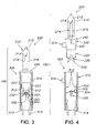
- FIG. 1 is a partial cross-sectional view of a first preferred embodiment of a lamp system for use in a light string system.
- a typical light string system comprises a plurality of lamp systems 100 connected in series, wherein each lamp system 100 has a light assembly 200 and a socket assembly 300.
- the light assembly 200 comprises a light source 210, a base 220 in communication with the light source 210, and a bypass activating system 230.
- the socket assembly 300 comprises a socket 310 adapted to receive the light assembly 200 and a bypass mechanism 320 having a first position and a second position.
- the light assembly 200 includes the light source 210.
- the light source 210 provides light when energized.
- the light source 210 can be many types of light sources, including a light bulb, light emitting diode (LED), incandescent lamp, halogen lamp, fluorescent lamp, and the like.
- the light source 210 is a light bulb.
- the light assembly 200, and more typically, the light bulb 210 of the light assembly 200 has a shunt device (not shown) to keep the light string system illuminated, even if the bulb 210 burns out.
- the light source 210 can include a globe 212 and a filament 214.
- the globe 212 is in communication with, and terminates at, the base 220.
- the globe 212 can be made of conventional translucent or transparent material such as plastic, glass, and the like.
- the globe 212 includes a hollow interior enabling protection of the filament 214.
- the filament 214 when charged with energy, illuminates the light source 210.
- Conductors 216 can be in electrical communication with the filament 214.
- the conductors 216 enable energy into the light source 210 to illuminate the filament 214, and as a result the light source 210.
- the conductors 216 extend down through the base 220, wherein preferably the conductors 216 can be in communication with a pair of lead wires 222 external the base 220.
- the lead wires 222 extend through a bottom of the base 220, and are a pair of wires wrapped around the base 220 extending upwardly in the direction of globe 212, adjacent the base 220.
- the light assembly 200 further includes the base 220.
- the base 220 can be integrally formed with the light source 210.
- the base 220 can be a unitary element of the light source 210, or a separate element.
- the base 220 communicates between the light source 210 and an associated socket 310, complimenting and facilitating the seating of the light assembly 200 to the socket 310.
- the base 220 can incorporate a least one ridge 226 (see Fig. 4 ) to ensure a snug fit with the socket 310, preventing the accidental disengagement of the light assembly 200 from the socket assembly 300.
- Other mechanical means can be used with the base 220 and the socket assembly 300 to ensure a tight fit.
- the light assembly 200 can also include a locking assembly to secure the light assembly 200 to the socket assembly 300.
- the locking assembly may be exterior, or designed within the socket assembly 300 to fasten the connection of the light assembly 200 to the socket assembly 300 internally.
- the locking assembly is external and can include cooperating light assembly elements 224 and socket assembly element 304. These elements 224 and 304 can be formed as a clasp and a lock to insert the clasp.
- the base 220 of the light assembly 200 can include the element 224 that extends normal to the base 220 and can define an aperture. On the other end of the locking assembly can be the element 304 from the socket 310 to be inserted into the element 224 of the base 220.
- the bypass activating system 230 preferably extends in a downward direction from base 220 of the light assembly 200, and is used to activate the bypass mechanism 320 of the socket assembly 300 upon the proper seating of the light assembly 200 therein.
- the bypass activating system 230 can be in a downward "V" shape (see Fig. 4 ).
- the bypass activating system 230 can be one or more extending members 232 (see Fig. 1 ).
- the socket assembly 300 comprises the socket 310 adapted to receive the light assembly 200.
- the socket 310 defines a cooperatively-shaped aperture to receive the base 220 of the light assembly 200.
- the socket 310 is also adapted to receive the whole of the bypass activating system 230 of the light assembly 200.
- the socket 310 can be arranged in many shapes and sizes, but as one skilled in the art will recognize, the socket 310 should be of a shape to conveniently receive the light assembly 200.
- the socket 310 includes a pair of socket terminals 312.
- the socket terminals 312 are, preferably, located on opposing inner sides of the socket 310.
- the socket 310 further includes a pair of terminal wires 314 extending to the exterior to allow energy to enter (and exit) the socket 310.
- Each socket terminal 312 is, essentially, an extension of each respective terminal wire 314.
- the terminal wire 314 extends through the bottom of the socket 310 and is ultimately connected to an electrical source. Therefore, the electrical current is introduced into the socket 310 by one of the terminal wires 314 and conducted either through the bypass mechanism 320 if in the first position, or through lead wires 222 to the filament 214 to illuminate the light bulb 210 if in the second position. Regardless of path, the current will flow to the other of the lamp systems 100 of the light string.
- the socket assembly 300 also includes the bypass mechanism 320.
- the bypass mechanism 320 includes a conductive element 322.
- the conductive element 322 sits, preferably, on a fulcrum 330 in the socket 310.
- the conductive element 322 has a first position and a second position.
- the bypass mechanism 320 is positioned on a centrally-positioned fulcrum of the socket assembly 300.
- the bypass mechanism 320 incorporates the conductive element 322, such that an electric circuit is provided from the left terminal wire 314, through the left socket terminal 312 across conductive element 322, and ultimately to the right terminal wire 314 via the right socket terminal 312.
- the conductive element 322 can be a spring mechanism 324.
- the socket 310 is dimensioned to receive the insertion of the bypass activating system 230, which forces the single spring 324 together, not apart, when the light assembly 200 is inserted into the socket 310.
- the single spring 324 springs apart, not together, when the light assembly 200 is removed from the light socket 310.
- the spring 324 sits about the fulcrum 330.
- the bypass activating system 230 pushes at least one side of the conductive element 322 down, distal the socket terminal 312 to "open" the circuit across 322. This disables the electrical connection that the bypass mechanism 320 created, and the circuit is closed via the bulb 210, not the conductive element 322. As shown in Fig. 3 , both sides of conductive element 322 are disengaged by the bypass activating system 230.
- the bypass mechanism 320 is a centrally fulcrumed spring mechanism about the fulcrum 330, and the two extending members 232 push both sides of the conducting element 322 away from the socket terminals 312. It will be understood that other bridging mechanisms can be used beyond fulcrum 330 to support the element 322 across the socket 310.
- the bypass activating system 230 can have one or more pointed or rounded tips that facilitate disconnecting the bypass mechanism 320 from the socket terminals 312.
- the bypass activating system 230 disables the physical connection of the bypass mechanism 320, thereby eliminating any electrically conductive path for the electrical current to flow, other than through the inserted assembly 200.
- the bypass mechanism 320 permits the removal of one or more light assemblies 200 of the lamp system 100, while maintaining the lighting of the remaining lights of a light string system.
- the bypass mechanism 320 creates a short circuit, and therefore enables current flow to keep other lamp systems 100 with energy at each socket 310.
- Each socket 310 can have a single current carrying bypass mechanism 320, which pushes away from the socket terminal 312 when the bypass activating system 230 engages the bypass mechanism 320 thereby breaking electrical continuity across the bypass mechanism 320.
- the lead wires 222 extending from the base 220 will make electrical contact with the socket terminals 312 completing the electrical circuit.
- the bypass mechanism 320 opens again and makes contact with the socket terminals 312, maintaining the electrical connection.
- the bypass mechanism 320 has a first position and a second position.
- the first position bypasses energy flow when a light assembly 200 is not properly seated in the socket 310 ( Figs. 1-2 ).
- the bypass mechanism 320 extends to make contact with the sides of the socket 310, the socket terminal 312.
- an electrical circuit is created, or a short circuit is formed. This situation arises when the light assembly 200 is missing from the socket 310.
- the second position enables energy to flow through the light source 210 to illuminate it ( Fig. 3 ) .
- the bypass mechanism 320 is removed from electrical communication from at least one side of the socket 310 (at least one socket terminal 312). The electrical circuit through the bypass mechanism 320 is disconnected, or an open circuit is formed.
- This situation typically arises when a light assembly 200 is fully inserted into the socket 310.
- the bypass activating system 230 pushes the bypass mechanism 320 together when the light assembly 200 is being seated in the socket 310; and the bypass mechanism 320 pushes apart when the light source 210 is being removed from the socket 310.
- Figs. 1-3 are partial cross sectional views of a preferred embodiment of the lamp system 100 illustrating the light assembly 200 being inserted into and fully seated in the socket 310.
- electrical current flowing through the bypass mechanism 320 is interrupted.
- electrical current flow is then enabled to flow through the lead wires 222 and up through the conductors 216 to illuminate the light source 210.
- the current then resumes flowing out through the opposite side of the conductor 216 and down through the other lead wire 222, passing through the other terminal wire 314 until it exits that particular lamp system 100.
- a flange 240 engages socket 310 when light assembly 200 is fully seated.
- Fig. 4 illustrates another preferred embodiment of the lamp system 100.
- the lamp system 100 includes the bypass activating system 230 shown having an upside down "V" shape.
- the shape of the bypass activating system 230 enables contact with the bypass mechanism 320, and further permits the switching of the bypass mechanism 320 from the first position to the second position. Additionally, in Fig. 4 , the bypass mechanism 320 is positioned upon the fulcrum 330.
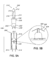
- Figs. 5A and 5B illustrates a cross sectional view of a lamp for use in a lamp system 100 further illustrating the detail of the bypass mechanism 320.
- the bypass mechanism 320 is preferably is a spring 324, one skilled in the art will appreciate describing the bypass mechanism 320 in terms of a spring 324.
- the spring 324 can be a single spring that is connected to the socket 310 with a fulcrum 330 in the socket 310. Providing a socket 310 with a centrally located, single fulcrum 330 enables easy manufacturability.
- the way the spring 324 is seated in the socket 310 can be by a pivot, hinge, pin, and the like, and need not be centrally located nor must the element 322 be a single element. It can include two or more elements that can be electrically communicative through the fulcrum 330. (Essentially, this is used in the embodiment in Figs. 9-11 , wherein the contacting member 342 is shown as two distinct members, electrically communicative one end to the other when the top of the biasing member 344 completes the path.)
- the spring 324 can be of the length to span the length of the diameter of the socket 310. In this arrangement, the spring 324 would create the short circuit by contacting the socket terminals 312. In alternative embodiments, the spring 324 can be in connection with a conductor (not shown) to span the length of the diameter of the socket 310.
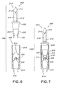
- Figs. 6-8 illustrate another preferred embodiment of the present invention.
- the bypass activating system 230 strikes only one branch of the bypass mechanism 320.
- the bypass mechanism 320 creates an open circuit by having the bypass activating system 230 to strike only one side of the bypass mechanism 320.
- the bypass activating system 230 includes two structures extending from the base 220 of the light assembly 200. Consequently, it will be understood by one in the art that the bypass activating system 230 can include a single extending member 232 extending from the base 220.
- the bypass mechanism 320 still includes a first position and a second position.
- the left side terminal 314 is always in electrical communication with the bypass mechanism 320, only the right side of the bypass mechanism 320 is activated between the first and second positions by the bypass activating system 230.
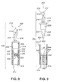
- Figs. 9-11 illustrate another preferred embodiment of the present invention.
- the bypass activating system 230 strikes a bypass mechanism 340 as a light assembly 200 is inserted into a socket 310.
- the bypass mechanism is a biasing member 344, of which at least the top portion is conductive.
- the biasing member can be, for example, a spring 346 or a topped, or a sheathed spring 346, should the spring 346 not be conductive, wherein at least the top or, the sheath of the spring 346, has a conductive layer to contact the contacting members 342 to provide an electrical path across the socket 310.
- the biasing member 344 can further be a zig-zag spring, a coiled spring, a hinge, and the like, wherein the top of the biasing member is electrically conductive.
- the light assembly 200 is adapted to be inserted into the socket 310.
- the socket 310 defines an aperture sufficiently sized to receive the light assembly 200.
- a pair of contacting members 342 are positioned at a predetermined depth of the socket 310.
- the contacting members 342 are, preferably, made of conductive material, e.g. , metal, copper, and the like.
- the contacting members 342 extend inwardly from opposing sides of the socket 310.
- the contacting members 342 are separated by a predetermined distance ( ⁇ d) to permit receiving the bypass activating system 230 therethrough.
- the bypass activating system 230 can contact the bypass mechanism 340.
- the lead wires 222 which are connected to the base 220 of the light assembly 200, contact the contacting members 342 enabling energy to flow through the light assembly 200.
- the bypass mechanism 340 includes two positions - a first position and a second position. The first position bypasses energy flow when the light assembly 200 is not seated in the socket 310. The second position of the bypass mechanism 320 enables energy to flow through the light source 210, therefore illuminating it.
- bypass mechanism 340 can be designed to move in an up and down motion, as the light assembly 200 is inserted into the socket 310, rather than pushed together and apart.
- Fig. 9 which depicts the first position of the bypass mechanism 340
- energy flows from the left terminal wire 314 to the left contacting member 342.
- the energy continues to flow through the conductive bypass mechanism 340, which acts like a shunt to connect the two contacting member 342.
- the energy then flows through the right contacting member 342 and out the right terminal wire 314.
- the bypass activating system 230 can push the bypass mechanism 320 away from the contacting members 342 to disable the shunt. Because at least a portion of the bypass activating system 230 is insulative, it prohibits energy to flow through the bypass mechanism 320 and, instead, allows illumination of the light source 210 of the light assembly 200.
- Figs. 12a-12b depict the biasing member 344 in another preferred embodiment.
- the biasing member 344 can be removed from engagement only at only end.
- the biasing member 344 is connected to one contacting member 342 by a hinge 348 or like device.
- the biasing member includes two positions - a first position and a second position. The first position, shown in Fig. 12a , exists when a light assembly 200 is absent from the socket assembly 300, and a coil spring or the like biases the member 344 to bring the gap ( ⁇ d ).
- the biasing member 344 makes contact with both contacting member 342 enabling a short circuit or shunt across the distance between the contacting members 342 ( ⁇ d ).
- the second position, shown in Fig. 12b , of the biasing member 344 exists when the light assembly is inserted into the socket assembly, wherein the biasing member 344 is disabled from the short circuit to an open circuit.
- Figs. 13-15 illustrate another preferred embodiment of the present invention.
- the bypass activating system 230 strikes a bypass mechanism 360 as a light assembly 200 is inserted into the socket 310.
- the bypass mechanism 360 is a moveable contact 362, which at least the top portion of which is conductive.
- the moveable contact 362 can be an electric conductor material having a spring-like property.
- the moveable contact 362 is adapted to be a bridging or shorting mechanism across a pair of contacting members 364.
- the bypass activating system 230 can push against the top of the moveable contact 362, wherein disabling the bridge or short across the contacting members 364.
- the light assembly 200 is adapted to be inserted into the socket 310.
- the socket 310 defines an aperture sufficiently sized to receive the light assembly 200.
- a pair of contacting members 364 are positioned at a predetermined depth of the socket 310.
- the contacting members 364 are made of conducting material, e.g. , metal, copper, and the like.
- the contacting members 364 extend inwardly from opposite sides of the socket 310.
- the contacting members 364 are separated by a distance ( ⁇ d ) enabling the bypass activating system 230 to fit therebetween.
- the bypass activating system 230 can make contact with the bypass mechanism 360.
- the lead wires 222 extending from the base 220 of the light assembly 200, can contact the contacting members 364, wherein energy can flow through the light assembly 200.
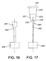
- the bypass mechanism 360 includes two positions - a first position and a second position. These positions are illustrated in Figs. 16-17 .
- the first position depicted in Fig. 16 , bypasses energy when the light assembly 200 is not seated in the socket 310.
- the second position of the bypass mechanism 360 depicted in Fig. 17 enables energy to flow through the light source 210, thereby enabling illumination of the light source 210.
- the bypass mechanism 360 which can be the moveable contact 362, is in communication with a stopper 366.
- the stopper 366 can be made of plastic, polymers, and the like. The stopper 366 provides the stability to the bypass mechanism 360 necessary to enable the moveable contact 362 be able to flex.
- the bypass mechanism 360 can be designed to move lateral to the longitudinal shape of the socket 310. Accordingly, instead of moving in an up and down direction (as previously described), the bypass mechanism 360 moves side to side. The bypass mechanism 360 moves away from contacting members 364 and moves towards the inner wall of the socket 310. As illustrated in Figs. 14-15 , the bypass activating system 230 is depicted in front of the bypass mechanism 360, since the extending member 232 pushes the bypass mechanism 360 away from the contacting members 364. This is depicted from a side view in Fig. 17 .
- Fig. 13 which depicts the first position of the bypass mechanism 360
- energy flows from the left terminal wire 314 to the left contacting member 364.
- the energy continues to flow through the conductive bypass mechanism 360, which acts like a shunt to connect the two contacting member 342.
- the energy then flows through the right contacting member 364 and out the right terminal wire 314.
- the bypass activating system 230 can push the bypass mechanism 360 away from the contacting members 364 to disable the shunt. Since at least a portion of the bypass activating system 230 is insulative, it prohibits energy to flow through the bypass mechanism 360 and, instead, allows illumination of the light source 210 of the light assembly 200 .
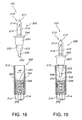
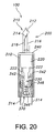
- Figs. 18-20 illustrate yet another embodiment of the present invention.
- Figs. 18-20 depict a sealing assembly 370 for sealing the socket 310.
- the sealing assembly 370 can protect the socket 310 from its environment.
- the sealing assembly 370 can limit, if not eliminate, moisture, water, and the like from entering the socket 310.
- the sealing assembly 370 can further act as a base support for the bypass mechanism 340.
- the sealing assembly 370 is preferably positioned between the two wires 314 and beneath the bypass mechanism 340, as to not interfere with the bypass activating system engaging the bypass mechanism 340.
- the sealing assembly 370 has a cup-like shape.
- a bottom of the sealing assembly 370 is substantially flat.
- a top of the sealing assembly 370 is open, for receiving the bypass mechanism 340, and sides of the sealing assembly 370 extend from the bottom to the top.
- the sealing assembly 370 is made of plastic; the sealing assembly 370 can be made of plastic, polymers, and the like.
Landscapes
- Engineering & Computer Science (AREA)
- General Engineering & Computer Science (AREA)
- Arrangement Of Elements, Cooling, Sealing, Or The Like Of Lighting Devices (AREA)
- Fastening Of Light Sources Or Lamp Holders (AREA)
- Non-Portable Lighting Devices Or Systems Thereof (AREA)
- Platform Screen Doors And Railroad Systems (AREA)
- Liquid Crystal (AREA)
- Devices For Conveying Motion By Means Of Endless Flexible Members (AREA)
- Road Signs Or Road Markings (AREA)
Applications Claiming Priority (4)
| Application Number | Priority Date | Filing Date | Title |
|---|---|---|---|
| US68655005P | 2005-06-02 | 2005-06-02 | |
| US21446005A | 2005-08-29 | 2005-08-29 | |
| US73450705P | 2005-11-08 | 2005-11-08 | |
| EP06760620A EP1920186B1 (de) | 2005-06-02 | 2006-06-02 | Lichtkettensystem |
Related Parent Applications (1)
| Application Number | Title | Priority Date | Filing Date |
|---|---|---|---|
| EP06760620.2 Division | 2006-06-02 |
Publications (3)
| Publication Number | Publication Date |
|---|---|
| EP2163818A2 true EP2163818A2 (de) | 2010-03-17 |
| EP2163818A3 EP2163818A3 (de) | 2010-03-31 |
| EP2163818B1 EP2163818B1 (de) | 2012-11-21 |
Family
ID=37481996
Family Applications (2)
| Application Number | Title | Priority Date | Filing Date |
|---|---|---|---|
| EP06760620A Active EP1920186B1 (de) | 2005-06-02 | 2006-06-02 | Lichtkettensystem |
| EP09015630A Active EP2163818B1 (de) | 2005-06-02 | 2006-06-02 | Lichtstreifensystem |
Family Applications Before (1)
| Application Number | Title | Priority Date | Filing Date |
|---|---|---|---|
| EP06760620A Active EP1920186B1 (de) | 2005-06-02 | 2006-06-02 | Lichtkettensystem |
Country Status (5)
| Country | Link |
|---|---|
| US (3) | US7264392B2 (de) |
| EP (2) | EP1920186B1 (de) |
| AT (1) | ATE460620T1 (de) |
| DE (1) | DE602006012850D1 (de) |
| WO (1) | WO2006130751A1 (de) |
Families Citing this family (64)
| Publication number | Priority date | Publication date | Assignee | Title |
|---|---|---|---|---|
| EP1920186B1 (de) * | 2005-06-02 | 2010-03-10 | GP Ltd | Lichtkettensystem |
| US7399110B2 (en) * | 2005-11-28 | 2008-07-15 | Cindex Holdings Limited (A Hong Kong Corporation) | Decorative light system |
| US20070133205A1 (en) * | 2005-12-13 | 2007-06-14 | Cindex Holdings Limited (A Hong Kong Corporation) | Dead wire housing assembly |
| CN200979133Y (zh) * | 2006-10-25 | 2007-11-21 | 陈琦 | 装饰灯 |
| US7967619B2 (en) * | 2006-10-25 | 2011-06-28 | Zheng Dianqing | Light string with improved shunt system |
| CN201246626Y (zh) * | 2008-08-18 | 2009-05-27 | 郑靛青 | 装饰灯 |
| US7819552B2 (en) | 2006-10-25 | 2010-10-26 | Seasonal Specialties Llc | Mechanical bypass light unit |
| US7253556B1 (en) | 2006-12-08 | 2007-08-07 | Tech Patent Licensing, Llc | Light string socket with mechanical shunt |
| US7771109B2 (en) * | 2007-02-07 | 2010-08-10 | Jetmax Industrial Ltd. | Lamp for light string |
| US20080186740A1 (en) * | 2007-02-07 | 2008-08-07 | Mike Huang | Connecting assembly in light strings to maintain electrical connection |
| US20080239758A1 (en) * | 2007-03-26 | 2008-10-02 | Kai Kong Ng | Snap-in lamp for an electric light string |
| US20080299817A1 (en) * | 2007-05-31 | 2008-12-04 | Chih-Ping Liu | Structure of lamp socket in lamp string |
| CN101319757B (zh) * | 2007-06-08 | 2011-01-12 | 云梦云曦灯饰制品有限公司 | 灯泡系统 |
| US7484995B2 (en) * | 2007-06-11 | 2009-02-03 | Hui Dong Xie Qun Lighting Manufacturing | Lamp system |
| US7554266B1 (en) | 2007-09-11 | 2009-06-30 | Willis Electric Co., Ltd. | Mechanical shunt for use in a socket in a string of lights |
| TWI355098B (en) * | 2007-09-21 | 2011-12-21 | Cheng Kung Capital Llc | Led lamp waterproof module |
| US7943211B2 (en) * | 2007-12-06 | 2011-05-17 | Willis Electric Co., Ltd. | Three dimensional displays having deformable constructions |
| US20090190359A1 (en) * | 2008-01-28 | 2009-07-30 | Cindex Holdings Limited (A Hong Kong Corporation) | Led light string system |
| GB0809610D0 (en) * | 2008-05-28 | 2008-07-02 | Miller Andrew | Transformer |
| US7629544B1 (en) * | 2008-06-03 | 2009-12-08 | Tech Patent Licensing, Llc | Asymmetric spring coil shunt for light string socket |
| US7626321B1 (en) | 2008-06-03 | 2009-12-01 | Tech Patent Licensing, Llc | Spring coil shunt for light string socket |
| US7626131B1 (en) | 2008-06-03 | 2009-12-01 | Tech Patent Licensing, Llc | Mechanical shunt for light string socket with self-cleaning feature |
| US7633024B1 (en) * | 2008-06-03 | 2009-12-15 | Tech Patent Licensing, Llc | Push rod shunt for light string sockets |
| US7453194B1 (en) | 2008-06-05 | 2008-11-18 | Gibboney James W | Mechanical shunt for use in the sockets of a string of lights |
| US7557497B1 (en) | 2008-09-22 | 2009-07-07 | Tech Patent Licensing, Llc | Asymmetric mechanical shunt switch for use in a socket of a string of lights |
| US7980871B2 (en) * | 2008-10-20 | 2011-07-19 | Polygroup Macau Limited (Bvi) | Light string system |
| US20100289415A1 (en) * | 2009-05-18 | 2010-11-18 | Johnny Chen | Energy efficient decorative lighting |
| US11013356B2 (en) | 2009-07-14 | 2021-05-25 | Belgravia Wood Limited | Power pole for artificial tree apparatus with axial electrical connectors |
| US10993572B2 (en) | 2009-07-14 | 2021-05-04 | Belgravia Wood Limited | Power pole for artificial tree apparatus with axial electrical connectors |
| US9833098B2 (en) | 2009-07-14 | 2017-12-05 | Loominocity, Inc. | Architecture for routing multi-channel commands via a tree column |
| US20110085327A1 (en) * | 2009-10-14 | 2011-04-14 | Johnny Chen | Decorative light display with LEDs |
| US20110221343A1 (en) * | 2009-12-08 | 2011-09-15 | Chengju Kuo | Decorative Lamp String with Open-Circuit-Proof and Over-Current-Proof Structure |
| US8235737B2 (en) | 2009-12-09 | 2012-08-07 | Polygroup Macau Limited (Bvi) | Light string system |
| CN201811064U (zh) * | 2010-07-27 | 2011-04-27 | 张冰 | 一种圣诞灯 |
| US8568015B2 (en) | 2010-09-23 | 2013-10-29 | Willis Electric Co., Ltd. | Decorative light string for artificial lighted tree |
| US8298633B1 (en) | 2011-05-20 | 2012-10-30 | Willis Electric Co., Ltd. | Multi-positional, locking artificial tree trunk |
| JP2013037989A (ja) * | 2011-08-10 | 2013-02-21 | Yazaki Corp | ソケット |
| US8863416B2 (en) | 2011-10-28 | 2014-10-21 | Polygroup Macau Limited (Bvi) | Powered tree construction |
| US9157587B2 (en) | 2011-11-14 | 2015-10-13 | Willis Electric Co., Ltd. | Conformal power adapter for lighted artificial tree |
| US8569960B2 (en) | 2011-11-14 | 2013-10-29 | Willis Electric Co., Ltd | Conformal power adapter for lighted artificial tree |
| US8876321B2 (en) | 2011-12-09 | 2014-11-04 | Willis Electric Co., Ltd. | Modular lighted artificial tree |
| US10206530B2 (en) | 2012-05-08 | 2019-02-19 | Willis Electric Co., Ltd. | Modular tree with locking trunk |
| US9572446B2 (en) | 2012-05-08 | 2017-02-21 | Willis Electric Co., Ltd. | Modular tree with locking trunk and locking electrical connectors |
| US9179793B2 (en) | 2012-05-08 | 2015-11-10 | Willis Electric Co., Ltd. | Modular tree with rotation-lock electrical connectors |
| US9044056B2 (en) | 2012-05-08 | 2015-06-02 | Willis Electric Co., Ltd. | Modular tree with electrical connector |
| CN203099480U (zh) * | 2013-02-04 | 2013-07-31 | 韩厚华 | 一种圣诞灯 |
| US9671074B2 (en) | 2013-03-13 | 2017-06-06 | Willis Electric Co., Ltd. | Modular tree with trunk connectors |
| US9439528B2 (en) | 2013-03-13 | 2016-09-13 | Willis Electric Co., Ltd. | Modular tree with locking trunk and locking electrical connectors |
| US9157588B2 (en) | 2013-09-13 | 2015-10-13 | Willis Electric Co., Ltd | Decorative lighting with reinforced wiring |
| US9140438B2 (en) | 2013-09-13 | 2015-09-22 | Willis Electric Co., Ltd. | Decorative lighting with reinforced wiring |
| US11306881B2 (en) | 2013-09-13 | 2022-04-19 | Willis Electric Co., Ltd. | Tangle-resistant decorative lighting assembly |
| US9894949B1 (en) | 2013-11-27 | 2018-02-20 | Willis Electric Co., Ltd. | Lighted artificial tree with improved electrical connections |
| US8870404B1 (en) | 2013-12-03 | 2014-10-28 | Willis Electric Co., Ltd. | Dual-voltage lighted artificial tree |
| US20150211726A1 (en) * | 2014-01-27 | 2015-07-30 | Yueh-Feng Wu Lee | Fully-waterproof and maintainable led christmas light |
| US9883566B1 (en) | 2014-05-01 | 2018-01-30 | Willis Electric Co., Ltd. | Control of modular lighted artificial trees |
| US9839315B2 (en) | 2015-03-27 | 2017-12-12 | Polygroup Macau Limited (Bvi) | Multi-wire quick assemble tree |
| US9444173B1 (en) * | 2015-06-04 | 2016-09-13 | Ford Global Technologies, Llc | Retractile socket adapter for 12V outlet |
| CA2946387A1 (en) | 2015-10-26 | 2017-04-26 | Willis Electric Co., Ltd. | Tangle-resistant decorative lighting assembly |
| US9907136B2 (en) | 2016-03-04 | 2018-02-27 | Polygroup Macau Limited (Bv) | Variable multi-color LED light string and controller for an artificial tree |
| US10615547B2 (en) * | 2016-09-08 | 2020-04-07 | Raytheon Company | Electrical device with shunt, and receptacle |
| US20180135843A1 (en) * | 2016-11-11 | 2018-05-17 | Xenio Corporation | Cartridge and socket for light fixtures |
| US10441014B1 (en) | 2017-01-03 | 2019-10-15 | Willis Electric Co., Ltd. | Artificial tree having multiple tree portions with electrical connectors secured therein |
| US10683974B1 (en) | 2017-12-11 | 2020-06-16 | Willis Electric Co., Ltd. | Decorative lighting control |
| US20250180177A1 (en) * | 2023-10-10 | 2025-06-05 | Matthew Roznovsky | Interchangeable Decorative Light String System |
Citations (4)
| Publication number | Priority date | Publication date | Assignee | Title |
|---|---|---|---|---|
| US5453664A (en) | 1994-02-01 | 1995-09-26 | Harris; Geoffrey H. | Light string with improved shunt system |
| US5702262A (en) | 1996-10-04 | 1997-12-30 | Trompeter Electronics, Inc. | Connector assembly |
| US6257740B1 (en) | 2000-02-11 | 2001-07-10 | James W Gibboney, Jr. | Lamp for use in light strings |
| US6533437B1 (en) | 2002-01-29 | 2003-03-18 | Joseph M. Ahroni | Apparatus, systems, and methods for maintaining power to a light string having light units arranged in series |
Family Cites Families (70)
| Publication number | Priority date | Publication date | Assignee | Title |
|---|---|---|---|---|
| US932129A (en) | 1908-09-11 | 1909-08-24 | George M Hughes | Door-hinge. |
| US1536332A (en) * | 1924-11-22 | 1925-05-05 | Monowatt Electric Imp Co Inc | Lamp socket for christmas-tree lighting |
| US2025564A (en) | 1932-12-24 | 1935-12-24 | Gen Electric | Electrical socket |
| US2576363A (en) | 1947-05-17 | 1951-11-27 | Westinghouse Electric Corp | Socket for series lamps and string thereof |
| US3359523A (en) | 1966-01-26 | 1967-12-19 | Lou Shih-Woo | Shunt device |
| US3915536A (en) * | 1972-02-23 | 1975-10-28 | Hellzen Bertil | Holder for an electric lamp |
| JPS5043092A (de) | 1973-08-20 | 1975-04-18 | ||
| FR2536594A1 (fr) | 1982-11-22 | 1984-05-25 | Droguet Int | Connecteur electrique et douille notamment pour guirlandes electriques |
| DE8327191U1 (de) | 1983-09-22 | 1983-12-29 | Schroff Gmbh, 7541 Straubenhardt | Führungsschiene mit Befestigungsvorrichtung für eine Steckerleiste |
| US4727449A (en) | 1986-10-01 | 1988-02-23 | Chiu Technical Corporation | Filament bypass circuit |
| JPS63164198A (ja) | 1986-12-25 | 1988-07-07 | 三菱電機株式会社 | パ−ソナルコンピユ−タの電源スイツチ |
| US4969071A (en) | 1988-06-13 | 1990-11-06 | U.S. Philips Corporation | Illumination set |
| US4894019A (en) * | 1988-06-16 | 1990-01-16 | Delta Systems, Inc. | Torsion spring shorting connector |
| JP2660562B2 (ja) | 1988-10-12 | 1997-10-08 | 日本信号株式会社 | ランプの断芯検出装置 |
| US4991071A (en) | 1989-04-14 | 1991-02-05 | Noma International, Inc. | Light string set |
| AU7177191A (en) | 1990-01-05 | 1991-07-24 | Joseph M. Ahroni | Improved chaser decorative light set and miniature light units |
| US5139393A (en) * | 1990-02-13 | 1992-08-18 | Hale Fire Pump Company | Thermal relief valve |
| JP3075804B2 (ja) | 1990-08-09 | 2000-08-14 | 森山産業株式会社 | 直列点灯装置 |
| US5071362A (en) * | 1990-10-12 | 1991-12-10 | Augat Inc. | Self-operative electrical shunting contact and method for forming |
| US5139343A (en) * | 1992-01-14 | 1992-08-18 | Lin Wen Hsiung | Lamp holder with switch means |
| DE9207136U1 (de) | 1992-05-26 | 1992-08-06 | Lin, Wen-Hsiung, Panchiao, Taipeh | Lampenhalter |
| JPH0641119A (ja) | 1992-07-24 | 1994-02-15 | Mitsui Toatsu Chem Inc | トリアジニルチオキノリン誘導体とその製造法およびこれを有効成分とする農園芸用殺菌剤 |
| US5281158A (en) | 1993-01-11 | 1994-01-25 | Lin Wen Hsiung | Light socket and socket adapter |
| JPH0787691A (ja) | 1993-09-14 | 1995-03-31 | Matsushita Electric Works Ltd | 無結線給電システム |
| US5455484A (en) | 1994-09-16 | 1995-10-03 | Matsushita Electric Works R&D Laboratory, Inc. | Adapter for simultaneously powering multiple compact fluorescent lamps utilizing an electronic ballast circuit |
| US5513081A (en) | 1995-04-27 | 1996-04-30 | Byers; Thomas L. | Multiple light installation and storage system |
| US7086758B2 (en) | 1995-06-26 | 2006-08-08 | Jlj, Inc. | Series connected light string with filament shunting |
| US20020047594A1 (en) | 1995-06-26 | 2002-04-25 | Janning John L. | Series connected light string with filament shunting |
| US7279809B2 (en) | 1995-06-26 | 2007-10-09 | Jlj, Inc. | Christmas light string with single Zener shunts |
| US7178961B2 (en) | 1995-06-26 | 2007-02-20 | Jlj, Inc. | Voltage regulated light string |
| CN1145242A (zh) | 1996-06-17 | 1997-03-19 | 杨景照 | 外用烧、烫伤药 |
| US5994845A (en) | 1997-04-24 | 1999-11-30 | Ventur Research & Development Inc. | Electrical light socket |
| JPH11185978A (ja) | 1997-12-24 | 1999-07-09 | Koito Ind Ltd | 照明装置 |
| JPH11288252A (ja) | 1998-04-01 | 1999-10-19 | Daichu Denshi:Kk | 点灯装置およびこれを用いた拡張型表示装置 |
| US6053774A (en) | 1998-10-28 | 2000-04-25 | Lin; Fong Shi | Miniature light bulb socket structure having an insert to keep wire terminals separate |
| US6203169B1 (en) * | 1999-06-25 | 2001-03-20 | Osram Sylvania Inc. | Lamp and method of producing same |
| US6283797B1 (en) | 1999-07-30 | 2001-09-04 | Jeng-Shyong Wu | Structure of a lamp base |
| JP2001076507A (ja) | 1999-09-03 | 2001-03-23 | Hongo Shizuko | 装飾用電球及びこれを用いた多灯照明器具 |
| US6203166B1 (en) | 1999-10-12 | 2001-03-20 | Gary Products Group, Inc. | Reconfigurable decorative star apparatus |
| US6630773B1 (en) | 1999-12-15 | 2003-10-07 | Shining Blick Enterprises Co., Ltd. | Assembling structure for lamp string with fully enveloped bulbs |
| US6224415B1 (en) | 2000-02-11 | 2001-05-01 | James W Gibboney, Jr. | Locking light socket and light |
| CN2458789Y (zh) | 2000-11-13 | 2001-11-07 | 潘文芳 | 一种灯串灯泡组的电流导通装置 |
| CA2441278C (en) | 2001-03-19 | 2009-12-29 | Integrated Power Components, Inc. | Decorative light string having shunt repair device |
| JP2003208993A (ja) | 2002-01-11 | 2003-07-25 | Toyoda Gosei Co Ltd | Led照明装置 |
| US6755552B2 (en) * | 2002-04-23 | 2004-06-29 | Hung-Wen Lee | Conductive plate of a bulb assembly |
| US6650065B1 (en) | 2002-05-22 | 2003-11-18 | Whiter Shieh | Decorative bulb unit with filament shunt mounted in bulb socket thereof |
| US6774549B2 (en) | 2002-08-21 | 2004-08-10 | Ching-Yen Tsai | Lamp structure of lamp string |
| CN2583839Y (zh) | 2002-11-19 | 2003-10-29 | 谢怀棠 | 圣诞灯座的分流器弹性接触结构 |
| US6805463B2 (en) * | 2002-12-03 | 2004-10-19 | Whiter Shieh | Shunt element contacting structure for decorative lamp holder |
| US6806656B2 (en) | 2002-12-16 | 2004-10-19 | Sienna Llc | Fuse bulb twinkle light set |
| CN2595018Y (zh) | 2003-01-09 | 2003-12-24 | 翁碧珠 | 防止灯串断路的灯组结构 |
| US6713971B1 (en) | 2003-01-09 | 2004-03-30 | Pi-Chu Wong | Lamp string with an open-circuit-proof structure |
| CN2702165Y (zh) | 2004-05-21 | 2005-05-25 | 嘉智集团有限公司 | 串联灯串及其灯座组件 |
| US20050286267A1 (en) * | 2004-06-29 | 2005-12-29 | Wang Jung K | Auto-contact bulb assembly |
| US7186017B2 (en) * | 2005-01-05 | 2007-03-06 | Cheng-Ju Kuo | Backstop socket structure for lamp string |
| EP1920186B1 (de) | 2005-06-02 | 2010-03-10 | GP Ltd | Lichtkettensystem |
| US7473024B2 (en) | 2005-08-30 | 2009-01-06 | Ventur Research & Development Corp. | Light strings including standard socket and longer-length non-standard keyed socket |
| US20070159109A1 (en) | 2006-01-09 | 2007-07-12 | Gibboney James W | String of lights with voltage regulation |
| US7963670B2 (en) | 2006-07-31 | 2011-06-21 | 1 Energy Solutions, Inc. | Bypass components in series wired LED light strings |
| US7819552B2 (en) | 2006-10-25 | 2010-10-26 | Seasonal Specialties Llc | Mechanical bypass light unit |
| US7253556B1 (en) * | 2006-12-08 | 2007-08-07 | Tech Patent Licensing, Llc | Light string socket with mechanical shunt |
| US20080186740A1 (en) * | 2007-02-07 | 2008-08-07 | Mike Huang | Connecting assembly in light strings to maintain electrical connection |
| US20080239758A1 (en) | 2007-03-26 | 2008-10-02 | Kai Kong Ng | Snap-in lamp for an electric light string |
| US20080258630A1 (en) | 2007-04-20 | 2008-10-23 | Collins Matthew D | Light String Lamp Bypass Device |
| US7484995B2 (en) * | 2007-06-11 | 2009-02-03 | Hui Dong Xie Qun Lighting Manufacturing | Lamp system |
| US7554266B1 (en) | 2007-09-11 | 2009-06-30 | Willis Electric Co., Ltd. | Mechanical shunt for use in a socket in a string of lights |
| US20090190359A1 (en) | 2008-01-28 | 2009-07-30 | Cindex Holdings Limited (A Hong Kong Corporation) | Led light string system |
| US7453194B1 (en) | 2008-06-05 | 2008-11-18 | Gibboney James W | Mechanical shunt for use in the sockets of a string of lights |
| US7557497B1 (en) | 2008-09-22 | 2009-07-07 | Tech Patent Licensing, Llc | Asymmetric mechanical shunt switch for use in a socket of a string of lights |
| US7980871B2 (en) | 2008-10-20 | 2011-07-19 | Polygroup Macau Limited (Bvi) | Light string system |
-
2006
- 2006-06-02 EP EP06760620A patent/EP1920186B1/de active Active
- 2006-06-02 EP EP09015630A patent/EP2163818B1/de active Active
- 2006-06-02 DE DE602006012850T patent/DE602006012850D1/de not_active Expired - Fee Related
- 2006-06-02 WO PCT/US2006/021242 patent/WO2006130751A1/en not_active Ceased
- 2006-06-02 AT AT06760620T patent/ATE460620T1/de not_active IP Right Cessation
- 2006-06-23 US US11/473,504 patent/US7264392B2/en not_active Expired - Lifetime
-
2007
- 2007-09-04 US US11/849,423 patent/US7581870B2/en not_active Expired - Lifetime
-
2009
- 2009-07-17 US US12/505,067 patent/US8047700B2/en not_active Expired - Lifetime
Patent Citations (4)
| Publication number | Priority date | Publication date | Assignee | Title |
|---|---|---|---|---|
| US5453664A (en) | 1994-02-01 | 1995-09-26 | Harris; Geoffrey H. | Light string with improved shunt system |
| US5702262A (en) | 1996-10-04 | 1997-12-30 | Trompeter Electronics, Inc. | Connector assembly |
| US6257740B1 (en) | 2000-02-11 | 2001-07-10 | James W Gibboney, Jr. | Lamp for use in light strings |
| US6533437B1 (en) | 2002-01-29 | 2003-03-18 | Joseph M. Ahroni | Apparatus, systems, and methods for maintaining power to a light string having light units arranged in series |
Also Published As
| Publication number | Publication date |
|---|---|
| DE602006012850D1 (de) | 2010-04-22 |
| US7264392B2 (en) | 2007-09-04 |
| US7581870B2 (en) | 2009-09-01 |
| US20060274556A1 (en) | 2006-12-07 |
| EP2163818A3 (de) | 2010-03-31 |
| EP1920186A4 (de) | 2008-11-26 |
| WO2006130751A1 (en) | 2006-12-07 |
| EP2163818B1 (de) | 2012-11-21 |
| US20090279325A1 (en) | 2009-11-12 |
| ATE460620T1 (de) | 2010-03-15 |
| US20070297196A1 (en) | 2007-12-27 |
| US8047700B2 (en) | 2011-11-01 |
| EP1920186A1 (de) | 2008-05-14 |
| EP1920186B1 (de) | 2010-03-10 |
Similar Documents
| Publication | Publication Date | Title |
|---|---|---|
| US7581870B2 (en) | Light string system | |
| US7980871B2 (en) | Light string system | |
| US8235737B2 (en) | Light string system | |
| US6533437B1 (en) | Apparatus, systems, and methods for maintaining power to a light string having light units arranged in series | |
| US6257740B1 (en) | Lamp for use in light strings | |
| US5139343A (en) | Lamp holder with switch means | |
| US7666036B1 (en) | Stay lit socket structure for LED light bulbs | |
| CA1048597A (en) | Safety circuit and socket construction | |
| US20090296397A1 (en) | Push rod shunt for light string sockets | |
| US7626131B1 (en) | Mechanical shunt for light string socket with self-cleaning feature | |
| CA1255754A (en) | Fiber optic wiring device control system | |
| CA2219386C (en) | Quick wire electrical socket | |
| EP1676289B1 (de) | Schutzschalter mit einer bimetallschnappscheibe | |
| US7090529B1 (en) | LED connector | |
| US7626321B1 (en) | Spring coil shunt for light string socket | |
| KR101840586B1 (ko) | 퓨즈 일체형 커넥터 | |
| US20050258777A1 (en) | Semiconductor chip with container and contact elements for use in a light socket | |
| US7629544B1 (en) | Asymmetric spring coil shunt for light string socket | |
| GB2071837A (en) | A rope light | |
| KR200211833Y1 (ko) | 간판용 형광등의 글로우스타터 | |
| CS277306B6 (cs) | Tepelná ochrana umístěná v zářivkovém zapalovači | |
| KR19980010625U (ko) | 형광 조명기구의 과열시 전원 차단장치 |
Legal Events
| Date | Code | Title | Description |
|---|---|---|---|
| PUAI | Public reference made under article 153(3) epc to a published international application that has entered the european phase |
Free format text: ORIGINAL CODE: 0009012 |
|
| PUAL | Search report despatched |
Free format text: ORIGINAL CODE: 0009013 |
|
| AC | Divisional application: reference to earlier application |
Ref document number: 1920186 Country of ref document: EP Kind code of ref document: P |
|
| AK | Designated contracting states |
Kind code of ref document: A2 Designated state(s): AT BE BG CH CY CZ DE DK EE ES FI FR GB GR HU IE IS IT LI LT LU LV MC NL PL PT RO SE SI SK TR |
|
| AK | Designated contracting states |
Kind code of ref document: A3 Designated state(s): AT BE BG CH CY CZ DE DK EE ES FI FR GB GR HU IE IS IT LI LT LU LV MC NL PL PT RO SE SI SK TR |
|
| 17P | Request for examination filed |
Effective date: 20100923 |
|
| 17Q | First examination report despatched |
Effective date: 20101019 |
|
| RAP1 | Party data changed (applicant data changed or rights of an application transferred) |
Owner name: POLYGROUP ASIA PACIFIC LIMITED |
|
| RAP1 | Party data changed (applicant data changed or rights of an application transferred) |
Owner name: POLYGROUP MACAU LIMITED |
|
| GRAC | Information related to communication of intention to grant a patent modified |
Free format text: ORIGINAL CODE: EPIDOSCIGR1 |
|
| GRAP | Despatch of communication of intention to grant a patent |
Free format text: ORIGINAL CODE: EPIDOSNIGR1 |
|
| GRAS | Grant fee paid |
Free format text: ORIGINAL CODE: EPIDOSNIGR3 |
|
| GRAA | (expected) grant |
Free format text: ORIGINAL CODE: 0009210 |
|
| AC | Divisional application: reference to earlier application |
Ref document number: 1920186 Country of ref document: EP Kind code of ref document: P |
|
| AK | Designated contracting states |
Kind code of ref document: B1 Designated state(s): AT BE BG CH CY CZ DE DK EE ES FI FR GB GR HU IE IS IT LI LT LU LV MC NL PL PT RO SE SI SK TR |
|
| REG | Reference to a national code |
Ref country code: GB Ref legal event code: FG4D |
|
| REG | Reference to a national code |
Ref country code: CH Ref legal event code: EP |
|
| REG | Reference to a national code |
Ref country code: AT Ref legal event code: REF Ref document number: 585282 Country of ref document: AT Kind code of ref document: T Effective date: 20121215 |
|
| REG | Reference to a national code |
Ref country code: IE Ref legal event code: FG4D |
|
| REG | Reference to a national code |
Ref country code: DE Ref legal event code: R096 Ref document number: 602006033282 Country of ref document: DE Effective date: 20130117 |
|
| REG | Reference to a national code |
Ref country code: NL Ref legal event code: VDEP Effective date: 20121121 |
|
| REG | Reference to a national code |
Ref country code: AT Ref legal event code: MK05 Ref document number: 585282 Country of ref document: AT Kind code of ref document: T Effective date: 20121121 |
|
| REG | Reference to a national code |
Ref country code: LT Ref legal event code: MG4D |
|
| PG25 | Lapsed in a contracting state [announced via postgrant information from national office to epo] |
Ref country code: ES Free format text: LAPSE BECAUSE OF FAILURE TO SUBMIT A TRANSLATION OF THE DESCRIPTION OR TO PAY THE FEE WITHIN THE PRESCRIBED TIME-LIMIT Effective date: 20130304 Ref country code: SE Free format text: LAPSE BECAUSE OF FAILURE TO SUBMIT A TRANSLATION OF THE DESCRIPTION OR TO PAY THE FEE WITHIN THE PRESCRIBED TIME-LIMIT Effective date: 20121121 Ref country code: FI Free format text: LAPSE BECAUSE OF FAILURE TO SUBMIT A TRANSLATION OF THE DESCRIPTION OR TO PAY THE FEE WITHIN THE PRESCRIBED TIME-LIMIT Effective date: 20121121 Ref country code: LT Free format text: LAPSE BECAUSE OF FAILURE TO SUBMIT A TRANSLATION OF THE DESCRIPTION OR TO PAY THE FEE WITHIN THE PRESCRIBED TIME-LIMIT Effective date: 20121121 |
|
| PG25 | Lapsed in a contracting state [announced via postgrant information from national office to epo] |
Ref country code: LV Free format text: LAPSE BECAUSE OF FAILURE TO SUBMIT A TRANSLATION OF THE DESCRIPTION OR TO PAY THE FEE WITHIN THE PRESCRIBED TIME-LIMIT Effective date: 20121121 Ref country code: PL Free format text: LAPSE BECAUSE OF FAILURE TO SUBMIT A TRANSLATION OF THE DESCRIPTION OR TO PAY THE FEE WITHIN THE PRESCRIBED TIME-LIMIT Effective date: 20121121 Ref country code: BE Free format text: LAPSE BECAUSE OF FAILURE TO SUBMIT A TRANSLATION OF THE DESCRIPTION OR TO PAY THE FEE WITHIN THE PRESCRIBED TIME-LIMIT Effective date: 20121121 Ref country code: GR Free format text: LAPSE BECAUSE OF FAILURE TO SUBMIT A TRANSLATION OF THE DESCRIPTION OR TO PAY THE FEE WITHIN THE PRESCRIBED TIME-LIMIT Effective date: 20130222 Ref country code: SI Free format text: LAPSE BECAUSE OF FAILURE TO SUBMIT A TRANSLATION OF THE DESCRIPTION OR TO PAY THE FEE WITHIN THE PRESCRIBED TIME-LIMIT Effective date: 20121121 Ref country code: PT Free format text: LAPSE BECAUSE OF FAILURE TO SUBMIT A TRANSLATION OF THE DESCRIPTION OR TO PAY THE FEE WITHIN THE PRESCRIBED TIME-LIMIT Effective date: 20130321 |
|
| PG25 | Lapsed in a contracting state [announced via postgrant information from national office to epo] |
Ref country code: AT Free format text: LAPSE BECAUSE OF FAILURE TO SUBMIT A TRANSLATION OF THE DESCRIPTION OR TO PAY THE FEE WITHIN THE PRESCRIBED TIME-LIMIT Effective date: 20121121 |
|
| PG25 | Lapsed in a contracting state [announced via postgrant information from national office to epo] |
Ref country code: EE Free format text: LAPSE BECAUSE OF FAILURE TO SUBMIT A TRANSLATION OF THE DESCRIPTION OR TO PAY THE FEE WITHIN THE PRESCRIBED TIME-LIMIT Effective date: 20121121 Ref country code: CZ Free format text: LAPSE BECAUSE OF FAILURE TO SUBMIT A TRANSLATION OF THE DESCRIPTION OR TO PAY THE FEE WITHIN THE PRESCRIBED TIME-LIMIT Effective date: 20121121 Ref country code: DK Free format text: LAPSE BECAUSE OF FAILURE TO SUBMIT A TRANSLATION OF THE DESCRIPTION OR TO PAY THE FEE WITHIN THE PRESCRIBED TIME-LIMIT Effective date: 20121121 Ref country code: SK Free format text: LAPSE BECAUSE OF FAILURE TO SUBMIT A TRANSLATION OF THE DESCRIPTION OR TO PAY THE FEE WITHIN THE PRESCRIBED TIME-LIMIT Effective date: 20121121 Ref country code: BG Free format text: LAPSE BECAUSE OF FAILURE TO SUBMIT A TRANSLATION OF THE DESCRIPTION OR TO PAY THE FEE WITHIN THE PRESCRIBED TIME-LIMIT Effective date: 20130221 |
|
| PG25 | Lapsed in a contracting state [announced via postgrant information from national office to epo] |
Ref country code: NL Free format text: LAPSE BECAUSE OF FAILURE TO SUBMIT A TRANSLATION OF THE DESCRIPTION OR TO PAY THE FEE WITHIN THE PRESCRIBED TIME-LIMIT Effective date: 20121121 Ref country code: IT Free format text: LAPSE BECAUSE OF FAILURE TO SUBMIT A TRANSLATION OF THE DESCRIPTION OR TO PAY THE FEE WITHIN THE PRESCRIBED TIME-LIMIT Effective date: 20121121 Ref country code: RO Free format text: LAPSE BECAUSE OF FAILURE TO SUBMIT A TRANSLATION OF THE DESCRIPTION OR TO PAY THE FEE WITHIN THE PRESCRIBED TIME-LIMIT Effective date: 20121121 |
|
| PLBE | No opposition filed within time limit |
Free format text: ORIGINAL CODE: 0009261 |
|
| STAA | Information on the status of an ep patent application or granted ep patent |
Free format text: STATUS: NO OPPOSITION FILED WITHIN TIME LIMIT |
|
| 26N | No opposition filed |
Effective date: 20130822 |
|
| REG | Reference to a national code |
Ref country code: DE Ref legal event code: R097 Ref document number: 602006033282 Country of ref document: DE Effective date: 20130822 |
|
| PG25 | Lapsed in a contracting state [announced via postgrant information from national office to epo] |
Ref country code: MC Free format text: LAPSE BECAUSE OF FAILURE TO SUBMIT A TRANSLATION OF THE DESCRIPTION OR TO PAY THE FEE WITHIN THE PRESCRIBED TIME-LIMIT Effective date: 20121121 |
|
| REG | Reference to a national code |
Ref country code: CH Ref legal event code: PL |
|
| REG | Reference to a national code |
Ref country code: IE Ref legal event code: MM4A |
|
| PG25 | Lapsed in a contracting state [announced via postgrant information from national office to epo] |
Ref country code: CH Free format text: LAPSE BECAUSE OF NON-PAYMENT OF DUE FEES Effective date: 20130630 Ref country code: IE Free format text: LAPSE BECAUSE OF NON-PAYMENT OF DUE FEES Effective date: 20130602 Ref country code: LI Free format text: LAPSE BECAUSE OF NON-PAYMENT OF DUE FEES Effective date: 20130630 |
|
| PG25 | Lapsed in a contracting state [announced via postgrant information from national office to epo] |
Ref country code: TR Free format text: LAPSE BECAUSE OF FAILURE TO SUBMIT A TRANSLATION OF THE DESCRIPTION OR TO PAY THE FEE WITHIN THE PRESCRIBED TIME-LIMIT Effective date: 20121121 Ref country code: CY Free format text: LAPSE BECAUSE OF FAILURE TO SUBMIT A TRANSLATION OF THE DESCRIPTION OR TO PAY THE FEE WITHIN THE PRESCRIBED TIME-LIMIT Effective date: 20121121 |
|
| PG25 | Lapsed in a contracting state [announced via postgrant information from national office to epo] |
Ref country code: LU Free format text: LAPSE BECAUSE OF NON-PAYMENT OF DUE FEES Effective date: 20130602 Ref country code: HU Free format text: LAPSE BECAUSE OF FAILURE TO SUBMIT A TRANSLATION OF THE DESCRIPTION OR TO PAY THE FEE WITHIN THE PRESCRIBED TIME-LIMIT; INVALID AB INITIO Effective date: 20060602 |
|
| REG | Reference to a national code |
Ref country code: FR Ref legal event code: PLFP Year of fee payment: 11 |
|
| PG25 | Lapsed in a contracting state [announced via postgrant information from national office to epo] |
Ref country code: IS Free format text: LAPSE BECAUSE OF FAILURE TO SUBMIT A TRANSLATION OF THE DESCRIPTION OR TO PAY THE FEE WITHIN THE PRESCRIBED TIME-LIMIT Effective date: 20121121 |
|
| REG | Reference to a national code |
Ref country code: FR Ref legal event code: PLFP Year of fee payment: 12 |
|
| REG | Reference to a national code |
Ref country code: FR Ref legal event code: PLFP Year of fee payment: 13 |
|
| PGFP | Annual fee paid to national office [announced via postgrant information from national office to epo] |
Ref country code: DE Payment date: 20251217 Year of fee payment: 20 |
|
| PGFP | Annual fee paid to national office [announced via postgrant information from national office to epo] |
Ref country code: GB Payment date: 20251119 Year of fee payment: 20 |
|
| PGFP | Annual fee paid to national office [announced via postgrant information from national office to epo] |
Ref country code: FR Payment date: 20251119 Year of fee payment: 20 |