EP2162625B1 - Apparatus and methods for securing a fastener - Google Patents
Apparatus and methods for securing a fastener Download PDFInfo
- Publication number
- EP2162625B1 EP2162625B1 EP08770905.1A EP08770905A EP2162625B1 EP 2162625 B1 EP2162625 B1 EP 2162625B1 EP 08770905 A EP08770905 A EP 08770905A EP 2162625 B1 EP2162625 B1 EP 2162625B1
- Authority
- EP
- European Patent Office
- Prior art keywords
- fastener
- nut
- receptacle
- base
- cage
- Prior art date
- Legal status (The legal status is an assumption and is not a legal conclusion. Google has not performed a legal analysis and makes no representation as to the accuracy of the status listed.)
- Not-in-force
Links
- 238000000034 method Methods 0.000 title claims description 19
- 229910052755 nonmetal Inorganic materials 0.000 claims description 9
- 238000003780 insertion Methods 0.000 claims description 6
- 230000037431 insertion Effects 0.000 claims description 6
- 239000000463 material Substances 0.000 description 25
- 230000000712 assembly Effects 0.000 description 12
- 238000000429 assembly Methods 0.000 description 12
- 230000008901 benefit Effects 0.000 description 9
- 239000002184 metal Substances 0.000 description 6
- 230000002787 reinforcement Effects 0.000 description 6
- 230000003014 reinforcing effect Effects 0.000 description 6
- 239000000853 adhesive Substances 0.000 description 5
- 230000001070 adhesive effect Effects 0.000 description 5
- 230000004888 barrier function Effects 0.000 description 5
- 238000005260 corrosion Methods 0.000 description 5
- 230000007797 corrosion Effects 0.000 description 5
- 239000007767 bonding agent Substances 0.000 description 3
- 238000004519 manufacturing process Methods 0.000 description 3
- 239000007769 metal material Substances 0.000 description 3
- 239000004820 Pressure-sensitive adhesive Substances 0.000 description 2
- 239000004963 Torlon Substances 0.000 description 2
- 229920003997 Torlon® Polymers 0.000 description 2
- 239000002390 adhesive tape Substances 0.000 description 2
- 230000000295 complement effect Effects 0.000 description 2
- 239000002131 composite material Substances 0.000 description 2
- 230000007704 transition Effects 0.000 description 2
- 208000016261 weight loss Diseases 0.000 description 2
- 239000004696 Poly ether ether ketone Substances 0.000 description 1
- 239000004962 Polyamide-imide Substances 0.000 description 1
- 229920004738 ULTEM® Polymers 0.000 description 1
- 229920004695 VICTREX™ PEEK Polymers 0.000 description 1
- 238000013459 approach Methods 0.000 description 1
- JUPQTSLXMOCDHR-UHFFFAOYSA-N benzene-1,4-diol;bis(4-fluorophenyl)methanone Chemical compound OC1=CC=C(O)C=C1.C1=CC(F)=CC=C1C(=O)C1=CC=C(F)C=C1 JUPQTSLXMOCDHR-UHFFFAOYSA-N 0.000 description 1
- 150000002118 epoxides Chemical class 0.000 description 1
- 239000000835 fiber Substances 0.000 description 1
- 230000009969 flowable effect Effects 0.000 description 1
- PCHJSUWPFVWCPO-UHFFFAOYSA-N gold Chemical compound [Au] PCHJSUWPFVWCPO-UHFFFAOYSA-N 0.000 description 1
- 230000005923 long-lasting effect Effects 0.000 description 1
- 238000012423 maintenance Methods 0.000 description 1
- 230000014759 maintenance of location Effects 0.000 description 1
- 230000013011 mating Effects 0.000 description 1
- 238000012986 modification Methods 0.000 description 1
- 230000004048 modification Effects 0.000 description 1
- 239000002991 molded plastic Substances 0.000 description 1
- 238000000465 moulding Methods 0.000 description 1
- ISWSIDIOOBJBQZ-UHFFFAOYSA-N phenol group Chemical group C1(=CC=CC=C1)O ISWSIDIOOBJBQZ-UHFFFAOYSA-N 0.000 description 1
- 239000004033 plastic Substances 0.000 description 1
- 229920003023 plastic Polymers 0.000 description 1
- 229920003223 poly(pyromellitimide-1,4-diphenyl ether) Polymers 0.000 description 1
- 229920002647 polyamide Polymers 0.000 description 1
- 239000004417 polycarbonate Substances 0.000 description 1
- 229920000515 polycarbonate Polymers 0.000 description 1
- 229920002530 polyetherether ketone Polymers 0.000 description 1
- 229920000642 polymer Polymers 0.000 description 1
- 238000003825 pressing Methods 0.000 description 1
- 230000009467 reduction Effects 0.000 description 1
- 239000007787 solid Substances 0.000 description 1
- -1 sonic welding Substances 0.000 description 1
- 238000005728 strengthening Methods 0.000 description 1
- 229920003002 synthetic resin Polymers 0.000 description 1
- 239000000057 synthetic resin Substances 0.000 description 1
- 239000013585 weight reducing agent Substances 0.000 description 1
- 238000003466 welding Methods 0.000 description 1
Images


Classifications
-
- F—MECHANICAL ENGINEERING; LIGHTING; HEATING; WEAPONS; BLASTING
- F16—ENGINEERING ELEMENTS AND UNITS; GENERAL MEASURES FOR PRODUCING AND MAINTAINING EFFECTIVE FUNCTIONING OF MACHINES OR INSTALLATIONS; THERMAL INSULATION IN GENERAL
- F16B—DEVICES FOR FASTENING OR SECURING CONSTRUCTIONAL ELEMENTS OR MACHINE PARTS TOGETHER, e.g. NAILS, BOLTS, CIRCLIPS, CLAMPS, CLIPS OR WEDGES; JOINTS OR JOINTING
- F16B37/00—Nuts or like thread-engaging members
- F16B37/04—Devices for fastening nuts to surfaces, e.g. sheets, plates
- F16B37/044—Nut cages
-
- F—MECHANICAL ENGINEERING; LIGHTING; HEATING; WEAPONS; BLASTING
- F16—ENGINEERING ELEMENTS AND UNITS; GENERAL MEASURES FOR PRODUCING AND MAINTAINING EFFECTIVE FUNCTIONING OF MACHINES OR INSTALLATIONS; THERMAL INSULATION IN GENERAL
- F16B—DEVICES FOR FASTENING OR SECURING CONSTRUCTIONAL ELEMENTS OR MACHINE PARTS TOGETHER, e.g. NAILS, BOLTS, CIRCLIPS, CLAMPS, CLIPS OR WEDGES; JOINTS OR JOINTING
- F16B37/00—Nuts or like thread-engaging members
- F16B37/04—Devices for fastening nuts to surfaces, e.g. sheets, plates
- F16B37/041—Releasable devices
- F16B37/043—Releasable devices with snap action
-
- F—MECHANICAL ENGINEERING; LIGHTING; HEATING; WEAPONS; BLASTING
- F16—ENGINEERING ELEMENTS AND UNITS; GENERAL MEASURES FOR PRODUCING AND MAINTAINING EFFECTIVE FUNCTIONING OF MACHINES OR INSTALLATIONS; THERMAL INSULATION IN GENERAL
- F16B—DEVICES FOR FASTENING OR SECURING CONSTRUCTIONAL ELEMENTS OR MACHINE PARTS TOGETHER, e.g. NAILS, BOLTS, CIRCLIPS, CLAMPS, CLIPS OR WEDGES; JOINTS OR JOINTING
- F16B39/00—Locking of screws, bolts or nuts
- F16B39/22—Locking of screws, bolts or nuts in which the locking takes place during screwing down or tightening
- F16B39/24—Locking of screws, bolts or nuts in which the locking takes place during screwing down or tightening by means of washers, spring washers, or resilient plates that lock against the object
Definitions
- fastener receivers for example nut plates.
- fasteners for example clip nut fasteners, nut cages and similar assemblies, methods of forming fasteners, methods of assembling fasteners, methods of securing panels and other components with fasteners and assemblies using such fasteners.
- Nut plates include a base or bottom plate supporting a nut or similar fastener element.
- the nut plate helps to hold components, for example panels, together when a fastener is engaged with the nut and tightened down.
- the nut receives a bolt, screw or other threaded element passed through the hole and threaded into the nut.
- Nut plates may be used in automobiles, appliances and aircraft, as well as in other applications.
- Panel fasteners may have a number of parts, most or all of which are metal. Metal is used for strength, corrosion resistance and other factors. However, the metal parts add appreciable weight to the final assembly. If the weight of a given part could be reduced, because of the number of individual parts, even small weight reductions in an individual component may add up to a significant weight reduction overall. Additionally, some metal materials may still experience some corrosion and may also be incompatible with surrounding materials.
- Fastener assemblies can be made that are lightweight, easy to assemble, and/or have a high load capability.
- a fastener assembly can also be made such that it is easier to maintain, as well as to allow easier maintenance of hardware secured by the fastener assembly.
- Fastener assemblies including nut plates are described that are easy to assemble, lightweight and more corrosion resistant than many conventional nut plates. Additionally, the fastener may be configured to be more compatible with composite structures. The described fastener assemblies including nut plates may also be easy to manufacture.
- the support includes a base for being supported on a support surface.
- the base includes a structure for supporting a fastener element wherein the structure is at least partly non-symmetrical about a plane other than a horizontal plane parallel to the base.
- the structure is non-symmetrical about a vertical transverse plane.
- the structure is symmetrical about one vertical plane and non-symmetrical about another vertical plane, for example symmetrical about a longitudinal vertical plane and non-symmetrical about a transverse vertical plane where the two vertical planes are perpendicular to each other.
- the fastener element may be movable in several directions in a plane substantially parallel to the base, and the structure has barriers limiting movement of the fastener element in one direction different than barriers limiting movement of the fastener element in an opposite direction.
- the fastener element can be inserted and removed from only one side of the support.
- the support in another example of a fastener receiver or support for a fastener element, includes a base for being supported on a support surface.
- the base can be substantially planar. One side of the base contacts the support surface, and the other side of the base supports the fastener element.
- the fastener element is inserted into and removed from the base from only one side of the base, for example in a direction parallel to the base.
- the fastener element is limited in its ability to pivot relative to the support by opposite side walls, and in another example the fastener element is limited in its ability to pivot relative to the support by opposite side walls and an end wall, for example an end wall between the opposite side walls.
- the opposite side walls can be substantially mirror images of each other, and may be substantially parallel to each other.
- a fastener receiver or support for a fastener element can include a support element for the fastener element and a structure on the support element for receiving the fastener element.
- the structure includes an opening configured to allow insertion and removal of the fastener element through the opening in a direction at least partly parallel to the support element.
- the opening allows insertion and removal in only one direction, for example from a front of the structure.
- a portion of the structure opposite the opening has at least one barrier, boss, post or bearing surface for limiting movement of the fastener element away from the opening.
- the at least one limiting element for example barrier or bearing surface, can also limit pivoting of the fastener element relative to the structure.
- the fastener receiver can have a flat surface on the base for contacting the support surface, means for securing the fastener receiver to the support surface (for example, but not limited to rivets, bolts, or other fasteners, adhesive, adhesive tape, double-sided adhesive tape, sonic welding, bonding agents or other means for fixing the fastener receiver to the support surface). They can also be configured to allow the fastener element, such as a nut, to float and/or pivot a desired amount relative to the support. Floating can be used to allow self-adjustment, and pivoting can be used to position the fastener element relative to the support so as to bear against multiple bearing surfaces to absorb loading applied to the fastener element.
- They can also be configured to allow releasable retention of the fastener element, for example through a restricted opening in the side of the structure whereby insertion and removal of the fastener element is accomplished through application of a non-trivial force in a given direction. Additionally, they can be configured so that the fastener element occupies a given surface area and a bearing structure occupies a surface area of comparable magnitude along at least one side of the fastener element, which may also be along opposite sides of the fastener element, or about three or more sides of the fastener element. They may also be configured to accommodate a fastener element having a relatively planar support structure and an at least partially cylindrical fastening structure for receiving a complementary fastener element wherein the cylindrical structure is partially surrounded by a wall in the fastener receiver.
- a fastener receiver having a non-metal support and fastener cage integral with each other.
- the support is supported on one surface and the fastener cage is opposite the surface.
- the support extends in substantially two dimensions, and in one example is substantially planar.
- the support includes an opening for receiving a shank or shaft of a fastener element to be engaged with a corresponding fastener element in the fastener cage, and no portion of the support extends around and reverses itself on the support to be spaced apart from the opening.
- the support can be curved rather than precisely planar, while still not curving or turning back on itself.
- the non-metal support and fastener cage are molded plastic, and can be formed from a material such as TORLON.
- the support can include one or more securing portions, and in the case of plural securing portions, a second securing portion can be on a side of the fastener cage opposite the first securing portion.
- a second securing portion can be positioned other than on an opposite side of the fastener cage from the first securing portion.
- first and second securing portions can be at right angles to each other, on the same side of the fastener cage, or otherwise.
- a fastener receiver has a non-metal support and fastener cage integral with each other wherein the fastener cage includes an opening in a side of the fastener cage.
- the opening can be used to insert a fastener into and remove a fastener from the fastener cage.
- the side opening is the only way for inserting and removing the fastener element.
- the fastener cage includes an opening in a front of the fastener cage. The front opening can be used to insert a fastener into and remove a fastener from the fastener cage. In this example, the front opening may be the only way for inserting and removing the fastener element.
- the fastener cage can have multiple surfaces against which corresponding surfaces on a fastener element can bear when the fastener element pivots.
- the fastener cage includes at least two surfaces against which corresponding surfaces on the fastener element bear at the same time when the fastener element pivots.
- the at least two surfaces can be side surfaces in the fastener cage, such as oppositely facing side surfaces.
- the fastener cage can also include one additional surface against which corresponding surfaces on the fastener element can bear, preferably simultaneously, when the fastener element pivots.
- additional surfaces can be provided by a post, column or other bearing surface located between oppositely facing side surfaces in the fastener cage and extend upward from a fastener support surface.
- the fastener includes a base, such as one having an "H" configuration
- the base can include tips configured so that three tips surfaces engage bearing surfaces in the fastener cage when the fastener element pivots.
- the fastener receiver in another example, includes a support and a fastener cage on the support for receiving a fastener element.
- the fastener cage includes an upper portion for receiving a portion of a fastener element body.
- the cage upper portion extends substantially parallel to the support and includes an opening through the upper portion where the wall defining the opening extends through an angle less than 360 degrees.
- the wall extends in a substantially partial circle, and in another example, the wall extends about 255 degrees.
- the opening includes an entrance spacing having a width sufficiently less than an outside dimension of the fastener element body so that some force is used to insert and withdraw the fastener element from the cage.
- the entrance is positioned on a longitudinally-extending side of the fastener receiver.
- the fastener cage can include side walls extending from the support to the cage upper portion for providing bearing surfaces against which a fastener element can bear when the fastener element pivots.
- a post or column can extend between the support and the cage upper portion for providing additional bearing surfaces.
- a fastener having a base is positioned in the fastener receiver above a support panel.
- the fastener base and the support panel have approximately the same height.
- the fastener cage has a height above the support approximately twice the base height.
- the cage can include an upper support panel for supporting the fastener from above, and the material thickness of the support panel can be approximately the same as the base height.
- side walls extending between the support and the upper support panel can extend a height slightly greater than a height of the fastener base.
- the support represents approximately a third of the height of the fastener receiver
- the side walls represent approximately a third of the height of the fastener receiver
- the upper support wall thickness represents approximately a third of the height of the fastener receiver.
- the fastener receiver is molded to have the described configuration.
- the fastener receiver or support for a fastener element includes a support element for the fastener element and a structure on the support element for receiving the fastener element.
- three bearing or pivot-preventing surfaces are provided and are contacted when a fastener element is supported by the support element and pivots in one direction, and in another example when the fastener element pivots in two different directions, such as in opposite directions.
- the bearing surfaces can be walls, posts, columns, bosses, and relatively fixed structures.
- fastener assemblies examples include fastener assemblies and of methods of making and using the fastener assemblies.
- benefits can be achieved in the structure or the method.
- fastener assemblies with a nut element held in a nut receptacle or support having substantial bearing surfaces may be easier to use and maintain.
- Fastener assemblies with nut elements having simple attachment elements may be easy to install and maintain.
- some fastener assembly configurations may also benefit from lighter-weight components, lower manufacturing cost and improved material compatibility and corrosion resistance.
- improvements can be achieved also in assembly, such as with symmetric nut elements, where insertion of the nut element into a nut cage is easier.
- nut cage configurations can improve the integrity of the final assembly, and may reduce the possibility of part failure.
- fastener assemblies may be used.
- panels using the fastener assembly may be simplified or may be assembled more efficiently.
- the fastener assembly may be configured to permit the bolt or other mating fastener element to be secured more easily.
- fastener assembly configurations and of methods of making and using the fastener assemblies are described herein, and some have particular benefits in being used together. However, even though these apparatus and methods are considered together at this point, there is no requirement that they be combined, used together, or that one component or method be used with any other component or method, or combination. Additionally, it will be understood that a given component or method could be combined with other structures or methods not expressly discussed herein while still achieving desirable results.
- a fastener assembly in the form of a nut plate 100 includes a fastener receiver in the form of a receptacle 102 ( FIGS. 1-14 ).
- the fastener receptacle supports a fastener element, in the present example a nut element 104 ( FIGS. 1-3 and 14 ).
- the nut element 104 receives a complementary fastener such as bolt 106 ( FIG. 14 ).
- the fastener assembly may or may not include the bolt 106, depending on whether or not the assembly is combined and sold with or without the bolt 106, for example.
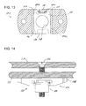
- the plate 102 includes a base 108 having an outward facing surface 110 ( FIG. 10 ) for being supported on a support surface 112 ( FIG. 14 ).
- the support surface 112 may be a frame structure, bulk head or other structural support.
- the bolt 106 extends through a panel or other component 114 and threads into the nut element 104 for securing the component 114 to the structure 112.
- the nut element 104 and bolt 106 may be otherwise configured to be secured together through means other than threads, such as detents, pins and grooves, latches, locking elements or the like.
- the outward facing surface 110 may be formed on a mounting plate, planar member, tab or tab combination, a plurality of wings, or other surfaces for helping to support the nut plate on the support surface 112.
- the outward facing surface 110 is formed on the base 108, which is a substantially planar plate member, and the outward facing surface 110 is substantially flat.
- the base 108 includes structures for mounting the base to the support surface 112.
- the base 108 includes openings 116 ( FIGS. 1 , 6 and 10 ) for receiving fasteners, for example rivets, threaded fasteners, and the like.
- the openings can be reinforced with respective eyelets (not shown), which may have cylindrical walls extending into the openings 116 and a perpendicular rim extending outward from the cylindrical wall.
- the openings can help to hold adhesives, films, double-stick tape or other pressure sensitive adhesives, or other bonding elements for holding the nut plate on the support surface.
- bonding agents or adhesives that might be flowable, such material may extend into the openings, may extend over the upper edges of the openings, and may also extend over part or all of the upper surfaces of the base. Contact of the material with the adjacent surface(s) of the base help to hold the nut plate in place. Engagement between the material and the adjacent edges of the nut plate help to hold the nut plate in place.
- Eyelets may be used in or around the openings to help resist loading forces that may be experienced through the nut plate when held in place through the mounting fasteners. Where adhesives, films, double-stick tape or other pressure sensitive adhesives, or other bonding elements are used, openings can also be omitted, with the bonding element holding the nut plate to the support surface through an appropriate bonding surface on the nut plate.
- the outward-facing surface 110 can incorporate a smooth or non-smooth surface adjacent to the intended support surface.
- a non-smooth surface can be textured, roughened, knurled, abraded, peened, inclusive of one or more projections or depressions, or otherwise varied. This non-smooth surface condition may improve the strength characteristics when joined to the support surface.
- the improved strength characteristics relate to the effectiveness of the attachment method of the nut plate with the intended support surface, which can include but is not limited to, peel, push-out, torque-out, and incidental jarring or hitting (with another object) of the attached nut plate.
- the base 108 is a substantially planar structure extending from a left side 118 to a right side 120.
- the base extends from a front surface 122 to a rear surface 124 ( FIGS. 3 and 6 ).
- the front and rear surfaces 122 and 124 are substantially straight and parallel to each other, and the left and right sides are slightly curved or have a radius.
- the base may have other profiles, however.
- the sides and front and rear surfaces extend substantially perpendicular to the outward facing surface 110.
- the base extends upward to an upper base surface 126 ( FIGS. 1 , 5 and 11 ).
- the upper base surface 126 supports the nut element 104.
- the upper base surface 126 is substantially flat and supports a substantially flat lower surface of the nut element 104.
- the upper base surface 126 allows the nut element 104 to pivot and/or float.
- the base forms a substantially planar support for the nut element, and one side of the base contacts the support structure to which it is mounted and the other side of the base supports the nut element.
- the base is substantially solid in this example, except for the fastener opening described herein.
- nut element rotation may made more difficult or otherwise limited, such as by making the upper base surface textured, knurled, roughened or otherwise non-smooth.
- pivoting can be reduced by such surface configurations in combination with non-smooth surfaces on the bottom of the nut element 104. If the bottom of the nut element 104 remains smooth, the nut element pivots easier than if it was also non-smooth.
- the base 108 also supports a support structure 130 ( FIGS. 1, 3 , 7 , 8 and 11 ).
- the support structure 130 also supports the nut element 104.
- the support structure 130 provides bearing support surfaces that accommodate torque loading applied when the nut is under torque.
- the support structure 130 also allows the nut element 104 to float a desired amount along an axis substantially perpendicular to the base 108.
- the support structure 130 forms a partial enclosure for the nut element 104 and includes side walls, left side wall surface 132 and right side wall surface 134, and upper wall surface 136. The side wall surfaces and the upper wall surface allow the nut element to pivot and to float.
- the left and right side wall surfaces are formed in the present examples as each having a full radius from the upper base surface 126 to the upper wall surface 136. They can also be formed each with two half radius portions connected by a substantially straight side wall or otherwise.
- the left and right side wall surfaces extend substantially straight between and perpendicular to the front and rear surfaces 122 and 124, respectively.
- the side wall surfaces and the upper wall surface along with the upper base surface 126 form a partial enclosure for the nut element and retain the nut element within the partial enclosure while limiting movement of the nut element both parallel to a plane defined by the upper base surface 126 and axially thereto.
- the left and right side wall surfaces are supported by left and right side walls 138 and 140, respectively ( FIG. 11 ).
- the left and right side walls are substantially identical mirror images of each other, and only one will be described.
- the left side wall 138 extends upwardly from the base 108 to an upper surface 142 and outward from the left side wall surface 132 to the left side 118.
- the left side wall 138 extends from the front surface 122 of the base 108 to the back surface 124, and has respective front and back walls substantially co-incident with the walls of the base 108.
- the upper surface 142 can extend outward substantially parallel to the lower surface 110 of the base 108 to the left side 118, but in the present example, the upper surface 142 slopes downward from a line 144 outboard of the left side wall surface 132 to a curved line 146. In the present example, the lowest point of line 146 is approximately at a midpoint in the left side wall surface 132 between the upper base wall 126 and the upper surface 136. In this configuration, the left side wall supporting the left side wall surface 132 extends substantially from the left side wall surface 132 to the left side 118 for supporting torque loading that may be applied by the nut element 104. In the configuration where the openings 116 are included in the nut plate, the left side wall extends around the respective opening.
- the opening 116 is a bore having a substantially cylindrical side wall 148 extending from the outward facing surface 110 upward to a counter bore 150 ( FIG. 11 ), though it should be understood that the counter bore 150 can instead be a countersink, a chamfered surface, a radiused transition, a raised boss or rim or other structure, or it can be omitted entirely.
- the cylindrical side wall 148 and counter bore 150 join at approximately the level of the curve 146. Both the bore and the counter bore 150 are preferably substantially circular.
- the bore and counter bore receive appropriate fasteners or other attachment means for substantially fixing the nut plate to the support surface.
- the openings in the present example are arranged on opposite sides of the nut 104. However, they can be positioned on the same side or at an angle relative to each other about the nut 104. Where the openings 116 are omitted, the side walls extend from the side wall surfaces to the respective outer sides.
- the left and right side walls extend toward each other over the upper base surface 126 and join at a bridge portion 152 ( FIGS. 1, 3 , 5 , 8 and 11 ).
- the left and right side walls and the bridge portion together are configured to define a partially circular wall 154 defining an opening 156 for aligning a barrel of the nut element, described more fully below.
- the opening 156 has a reduced-width entrance 158 to allow the barrel of the nut element to be press fit through the entrance and into the opening 156. Because of the minimum spacing defining the entrance being somewhat smaller than the outside diameter of the barrel, the barrel will not come out of the opening without a similar guiding force.
- the minimum spacing is defined by respective opposite walls 160 and 162 ( FIGS.
- the lead in to the entrance 158 is defined by a pair of diverging walls 164 and 166 extending outwardly from the respective sides of the entrance to the front sides of the side walls. The diverging surfaces help guide the nut into the opening 156.
- the opening 156 is larger than but co-axial with an opening 168 in the base 108.
- the opening 168 is formed by a completely circular wall through the base.
- the opening 168 receives the fastener 106 for threading into the nut element 104.
- the partial enclosure for the nut element may include a boss, post, column or rib 170.
- the column 170 extends upward from the upper base surface 126, and in the present example extends upward to the surface 136 and supports the bridge portion 152.
- the column 170 is substantially centered between the left and right side wall surfaces 132 and 134, respectively, and includes similarly radiused surfaces.
- the upper base surface 126, the column 170, the upper surface 136 and the left and right side wall surfaces define between them left and right openings 172 and 174 ( FIG. 8 ) for receiving respective projections, points or tabs on the nut element 104.
- the width of the openings 172 and 174 are selected according to the desired pivoting movement to be allowed for the nut element.
- the height of the openings are selected according to the desired float for the nut element.
- the configurations of the side surfaces of the column 170 and the inside wall surfaces 132 and 134 define the cross-sectional configurations of the openings, but the opening configurations can be different than the configurations of the side wall surfaces.
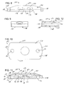
- the nut plate has at least the portion between the lines 144 symmetric about a longitudinal vertical plane such as that defined by the line 12-12 in FIG. 6 .
- This configuration shown in FIGS. 1-13 also has the entire nut plate symmetric about that plane.
- the nut plate is asymmetric about a vertical transverse plane defined by a line 11-11 in FIG. 6 , because the present example does not have a front column corresponding to the column 170, and the entrance 158 omits a bridge portion corresponding to the bridge portion 152. Therefore, the nut plate is asymmetric relative to a vertical transverse plane defined by the line 11-11.
- the nut plate is also asymmetric relative to a horizontal plane, such as that defined by line 13-13 in FIG. 7 .
- the edge portions of the nut plate surfaces may all be radiused, if desired.
- the side wall surfaces 132 and 134 and the column 170 provide limiting elements, bearing elements, bearing surfaces or barriers limiting movement of the fastener element. They limit pivoting movement of the nut element.
- the bearing surfaces provide three points of contact or three areas of contact (104a, 104b and 104c in FIG. 13 ) for receiving the torque loading applied by the nut element when the fastener is tightened down.
- the loading is supported by one side or the other of the column 170 and by the side walls 138 and 140 ( FIGS. 11 and 13 ).
- the nut element 104 ( FIGS. 1-4 ) includes a base 176 supporting a generally cylindrical internally threaded portion in the barrel 178.
- the barrel extends from the base 176 to an end surface 180 defining an opening for the barrel.
- the barrel may be substantially cylindrical in its inside and outside profile, or the barrel can be crimped to increase the frictional engagement with the fastener (for example 106).
- the nut can also be a beam locking nut, or other nut configurations.
- the base 176 of the nut has a substantially smooth, flat bottom surface and a substantially smooth, flat upper surface.
- the upper surface curves from the flat surface upward to the outer perimeter surface of the barrel 178.
- the nut element 104 includes tips 180 extending outward from the base 176.
- the tips 180 can take the form of projections, pads, arms, extensions, points, cam surfaces, eccentricities or other surfaces which keep the base from having a circular perimeter.
- the tips 180 are arranged in pairs on each side of a transverse plane and each pair extends along a longitudinal plane.
- the tips 182 and 184 in the first pair extend in a direction opposite to the tips 186 and 188 in the other pair.
- the tip 182, and each tip in the example of the nut 104 includes a substantially straight wall 190 forming an inside surface of the tip 182, and an angled surface 192 forming an outside surface of the tip 182.
- the straight and angled surfaces end at a transverse flat end wall 194.
- pivoting of the nut 104 may cause the straight surface 190 to contact a bearing surface, the angled surface 192 to contact a corresponding bearing surface, or the respective junctions between those walls and the end wall 194 to contact a bearing surface.
- some configurations may have the flat end wall 194 contacting a bearing surface.
- the nut 104 in the present example is a conventional nut such as that shown and described in U.S. Pat No. 6,854,941 , incorporated herein by reference.
- the nut in the patent is formed from metal and is symmetric about both the transverse and longitudinal planes. Consequently, the nut can be inserted into the receptacle in two orientations, one 180 degrees apart from the other.
- the nut 104 can have the same configuration if desired.
- the nut is inserted into the nut receiving area by directing one pair of the tabs of the nut between the surfaces 164 and 166.
- the barrel 178 is pressed through the opening 158.
- the tabs 186 and 188 are guided into the openings 172 and 174, respectively.
- the nut element moves into position with the tabs 186 and 188 in the openings 172 and 174, the nut settles onto the upper base surface 126.
- the nut element can be removed by pressing the barrel 178 of the nut element out of the opening 158.
- the nut support is formed from a non-metal material.
- one material is TORLON, and other polyamide imides as well as other structural plastics or polymers can be used, including but not limited to among others; Vespel or Aurum (PI), Ultem (PEI), Victrex or Ketaspire (PEEK), Primospire (SRP), Polycarbonate, or Epoxide or Phenolic synthetic resins.
- the material can also be a composite material and may include fiber reinforcement or other strengthening materials. In these examples, only the nut and the fasteners securing the nut plate, if fasteners are used to secure the nut plate, are formed from a metal.
- Nut plates formed from non-metal materials with these or similar characteristics provide relatively high strength, and long lasting components that have relatively high resistance to corrosion. Additionally, molding of nut plates using such materials also permits manufacture of a number of nut plate configurations that can incorporate easily one or more of the features described herein.
- the nut element is formed from metal and is symmetric about both the transverse and longitudinal planes. Consequently, the nut can be inserted into the nut plate in two orientations, one 180 degrees apart from the other.
- Other nut element configurations can be used, with or without changes in the nut plate configuration.
- the nut element could be made asymmetric as well as having other configurations.
- the structures supporting and retaining the nut can be configured with a number of bearing surfaces against which projections or contact surfaces on the nut can bear when the nut is under torque, for example bosses, cavities, openings, walls and the like. These bearing surfaces can also include flats or other non-circular portions.
- the nut plates and the nut elements both can be configured, though they need not be, to be at least in part complimentary with each other.
- the nut 104 includes tabs that fit into the openings 172 and 174 of the nut support, and side walls in the base.
- the tabs and the sidewalls of the nut base substantially simultaneously bear against and are supported against further pivoting by complimentary surfaces in the nut support.
- the nut support may have a plurality of convergent surfaces or walls so that at least some of the nut element surfaces on the star points contact respective ones of the convergent surfaces substantially simultaneously when the nut element pivots.
- the nut support can include rounded bearing surfaces. If the nut element has squared off tabs with straight side walls, the complimentary bearing surfaces on the nut support can also have flat bearing surfaces. Other combinations can also be used.
- any of the nut plate combinations described herein can rotationally fix the nut in place during normal usage, it is preferred to allow some rotational movement of the nut relative to the receptacle. Additionally, it is also preferred that when the nut is under torque, any projections or tabs or other surfaces that are intended to engage bearing surfaces on the nut support when the nut is under torque preferably contact those bearing surfaces substantially simultaneously, or if not simultaneously, all of the surfaces intended to engage bearing surfaces on the receptacle achieve the intended engagement.
- the height or thickness of the base 108 can occupy about one-third of the overall height of the nut plate.
- the distance or spacing between the upper base surface 126 and the upper surface 136 may occupy about another third of the overall height of the nut plate.
- the thickness of the bridge portion 152 between the upper surface 136 and the surface 142 may occupy about another third of the overall height of the nut plate.
- the spacing between the walls 132 and 134 may be between one-third and one-half the overall width of the nut plate between the ends 118 and 120. The remainder of the width is split substantially equally between the side walls 138 and 140.
- the nut assembly 100 of FIG. 1 is fastened to the support element 112 so that the opening 168 is substantially coaxial with an opening in the support element.
- the fastener 106 is pressed through the opening in the panel 114 and threaded into the nut 104.
- the nut element is biased away from the panel 114, until the threads of the fastener 106 engage and advance into the nut element 104. Further threading of the fastener 106 pulls the nut against the upper surface 126 of the base 108. Further threading of the fastener 106 also pulls the panel 114 against the support element 112 and secures all the components together.
- nut plate 300 provides a side-load nut assembly and a single lug or mounting tab for the configuration.
- the nut plate will be considered as having a configuration for receiving and supporting a nut such as nut 104 ( FIG. 5 ), but the nut plate can be configured for receiving and supporting other nut configurations.
- the nut plate 300 includes a base 302 supporting a nut cage 304 for receiving and supporting a nut 104.
- the base 302 is configured to be mounted on an underlying support structure, such as that described with respect to FIG. 14 .
- the internal structure of the nut cage 304 is substantially the same as that described with respect to FIGS. 1-13 , and the height of the base 302, the height of the cage side walls and the height (or material thickness) of the upper support wall are substantially the same as those described with respect to FIGS. 1-13 .
- the base 302 is substantially planar and extends from a right end 306 to a left end 308.
- the base includes a bottom support surface 310 placed against an underlying support structure and secured thereto.
- the upper surface 312 of the base supports the cage 304.
- the base includes a single lug 314.
- Two openings 316 are formed through the lug 314 for receiving rivets or other fasteners for mounting the nut plate to the underlying structure.
- a single opening or more than two openings can be used, as desired, and the number, size and location may be selected as a function of the expected loading, the available space, and whether other securing means are used, such as adhesive or bonding agents.
- a single lug nut plate may be useful in limited space applications, along surface edges or corners or interior to the edges of a structure. In the present example, both openings are located on the same side of nut element, as opposed to on opposite sides or at an angle relative to the nut element, which are also possible.
- Each hole can include a respective eyelet 318 ( FIGS. 22-24 and 26-27 ) for example when significant loading is expected or when fasteners are used formed from a material harder than the material of the lug of the nut plate.
- One or more reinforcing walls 320 can be included for supporting the nut cage 304 relative to the base 302.
- the reinforcing walls 320 extend from the right side of the nut cage 304 to the upper surface of the base 302, on respective sides of the openings 316.
- the reinforcing walls 320 slope downwardly from the upper surface of the cage to the upper surface of the base 302.
- the reinforcing walls have a substantially constant slope downward and terminate approximately at a mid portion of the rightmost opening 316.
- the reinforcing walls have approximately the same material thickness as that for the nut cage side walls. However, the thickness can be different if desired.
- the access opening 322 ( FIGS. 24 and 26 ) for the nut cage in the present example is positioned at a side of the nut plate, rather than at a front or rear of the plate.
- the nut 104 is inserted in and removed from the cage through only the single access opening 322, and following a path that is substantially parallel to the upper surface of the base 302.
- locating the access opening 322 and suitable guiding of the nut 104 may be made easier by slightly tilting the nut 104 until tabs of the nut contact the upper surface of the base 302 followed by insertion parallel to the upper surface.
- eyelets such as eyelet 318 ( FIG. 27 ) can be used in conjunction with securement openings in the nut plate.
- the eyelets 318 shown in FIGS. 22-24 and 26-27 include a cylindrical portion 324 extending part or all of the way into the opening 316.
- a rim or flange 326 extends outwardly from an end portion of the cylindrical portion 324, for example for overlying or protecting a portion of the upper surface of the base 302.
- the rim 326 can also be recessed or set into the upper surface so that the top surface of the rim is flush with the upper surface of the base.
- Other eyelet configurations can also be used.
- lug arrangements can be used with the side-loading nut cage.
- other nut loading configurations can be used with the single lug securement configuration.
- an alternative nut plate 330 with a front-loading cage 332 configuration is included on a single lug base 334.
- the reinforcing walls 336 are thicker than the vertical walls 338 and 340 of the cage 332, but the nut plate 330 can be otherwise identical to the nut plate 300.
- FIGS. 29-31 a receptacle for a nut plate combination is shown in FIGS. 29-31 .
- the receptacle 400 is configured to accommodate the nut 104 described with respect to FIG. 4 , but the receptacle can be configured to accommodate a nut having other configurations.
- the nut 104 is not shown with the receptacle 400, but it is understood that the nut 104 can be inserted into and removed from the nut cage and would be supported in the nut cage in a manner substantially the same is that described above with respect to the nut in FIG. 4 .
- the receptacle 400 includes a base 402 supporting a cage 404.
- the base includes a bottom support surface 406 that will be placed against and secured to an underlying support structure.
- the base includes a right lug 408 and a left lug 410, each extending away from respective sides of the cage 404.
- the receptacle 400 is considered to have a front-loading cage 404 so that the lug 408 is on the right side and the lug 410 is on the left side of the cage.
- Each lug includes a respective opening 412 that can be used to assist in securing the receptacle to the underlying support structure.
- Each opening 412 can be considered as being centered approximately equidistant from the external sides of the respective lug, for example the distance defined by a radius 414 from a center of the opening to the outside of the rounded edge of the respective lug.
- each lug is directed forward toward the front of the receptacle so as to be directed at an angle (represented by the angle formed between the line 416 in FIG. 30 and the right side of the cage 404) from the adjacent side of the cage 404.
- each opening 412 is positioned closer to the front of the cage than to the rear of cage.
- each lug includes a portion that extends forward of the front of cage, in the present example.
- the receptacle can be used to support a fastener element near a corner of a panel, for example.
- An opening 418 is formed through the base for receiving an appropriate portion of a fastener element, as is typical for nut plates.
- the base 402 supports the nut cage 404.
- the nut cage includes a right side wall 420 and a left side wall 422 extending upward from the upper surface of the base 402 to an upper panel 424.
- the interior structural details of the nut cage are substantially identical to those described above with respect to the nut plates of FIGS. 1-14 and 22-28 .
- the interior of the nut cage 404 includes a substantially planar nut support surface 426, radiused internal side walls facing each other and extending upward to the upper panel 424 and a boss, post, column, or rib 428.
- the column 428 extends from the nut support surface 426 to the upper panel surface 424 and defines respective openings 430 and 432 for receiving and supporting respective tabs on a nut 104.
- the respective heights of the base, the internal side walls of the cage and of the upper panel 424 are preferably comparable to the relative dimensions of those structures described with respect to the other cages described herein.
- the height or material thickness of the base 402 is approximately one-third of the overall height of the receptacle, as is the height or material thickness of the upper panel 424, leaving the remaining approximately third of the height taken up by the interior of the cage.
- the side wall thicknesses of the side walls 420 and 422, namely the material thickness between the interior wall surfaces of the side walls and the exterior wall surfaces of the side walls can be selected to reliably support any loading applied from the tabs of a nut 104 when under loading.
- the side walls are radiused on the inside and straight on the outside with transition radii to and from adjacent surfaces.
- the side walls can slant or slope downwardly to join the upper surfaces of the adjacent lugs 408 and 410.
- the side walls can extend sideways to the outer edge surfaces of the respective lugs.
- Forming, assembling and installing a nut plate assembly having the receptacle 400 can be accomplished in a manner the same as or similar to the other examples described herein.
- a receptacle 500 ( FIGS. 32-33 ) is substantially identical to the receptacle 102 described with respect to FIGS. 1-14 .
- the receptacle 500 receives and supports the nut 104 through a front-loading configuration with the cage 502 on a support 504.
- the support 504 includes a downwardly-facing concave support surface 506 so that the support surface 506 is not planar.
- the curved support surface 506 allows the receptacle to be mounted on curved surfaces. In the configuration of the receptacle 500 shown in FIGS.
- the curvature is with respect to a minor axis extending in the front-to-rear direction, with the right and left sides 508 and 510, respectively, curving away from and extending on opposite sides of the minor axis.
- the curvature of the support surface 506 is substantially constant as shown in FIGS. 32 and 33 .
- the curvature can be concave relative to a major axis extending between the left and right sides of the receptacle, with the front and rear portions of the receptacle extending on opposite sides of the major axis.
- the curvature can be varied to accommodate the particular surface configuration of the underlying support structure.
- a receptacle 600 ( FIGS. 34-36 ) is substantially identical to that described with respect to FIGS. 15-18, except as described with respect to this example and without the front and rear support elements 210 and 212. Additionally, the cage configuration, and therefore the intended nut configuration for use therewith, corresponds to the nut 104. However, the cage and nut configuration can be incorporated similar to that described with respect to FIGS. 15-21, or other nut configurations.
- the base 602 extends front to rear and from the right side 604 to the left side 606.
- the base 602 includes a convex support surface 608 so that the support surface 608 is not planar.
- the curved support surface 608 allows the receptacle to be mounted on curved surfaces that are concave.
- the curvature is with respect to a minor axis extending in the front-to-rear direction, with the right and left sides 604 and 606, respectively, curving away from and on opposite sides of the minor axis.
- the curvature of the support surface 608 is substantially constant as shown in FIGS. 34 and 36 .
- the curvature can be convex relative to a major axis extending between the left and right sides of the receptacle, with the front and rear portions of the receptacle curving away from and on opposite sides of the major axis.
- the curvature can be varied to accommodate the particular surface configuration of the underlying support structure.
- the receptacle 600 can include openings 610 having central axes 612 configured so that the axes extend normal to the support surface 608.
- fasteners used to secure the receptacle 600 to the underlying support structure would extend normal to the underlying surface of the support structure adjacent the support surface 608.
- the fasteners and the surrounding support structure material may experience less side loading than if the fasteners were oriented otherwise.
- the openings and their central axes 612 can be oriented normal to the upper surface 614 of the receptacle 600 or at another angle.
- the receptacle 500 shown in FIGS. 32 and 33 can also have their openings oriented normal to the underlying support surface 506 at the point where the openings exit the support surface 506. Other configurations are also possible.
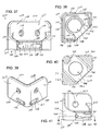
- a receptacle 700 ( FIGS. 37-41 ) can be used to mount a component or other structure adjacent a corner of two other structures, for example adjacent a corner in two panels.
- the receptacle 700 includes a base 702 that includes a bottom surface 704 forming a support surface 706 that is placed against an underlying support structure.
- the support surface 706 is substantially planar to be placed against a correspondingly planar portion of a support structure.
- the base is also substantially planar and has a uniform height or material thickness from the support surface 706 to the plane defined by a nut support surface 708.
- the base has a pentagon shape with two substantially equal-length right and left rear sides 710 and 712, respectively, and two substantially equal-length right and left front sides 714 and 716, respectively, the latter two of which are joined by front side 718.
- the right and left front sides are shorter in length than the right and left rear sides.
- the base 702 also includes an opening 720 for receiving a shank, shaft or other fastener element to be engaging the nut supported in the cage, described more fully below.
- the receptacle 700 includes a least one, and in the present example two, securement portions on the base for helping to secure the receptacle relative to the support structure.
- a right securement portion 722 and a left securement portion 724 are supported by and extend upwardly from the base 702.
- the right securement portion 722 extends upwardly from the base adjacent the right rear side 710
- the left securement portion 724 extends upwardly from the base adjacent the left rear side 712. They extend upward to upper edges 726 and 728, respectively.
- Each securement portion includes at least one, and if desired a plurality of, openings 730 for use in securing the receptacle to a support structure.
- the openings can be used to secure the receptacle in the same way that other receptacles described herein are secured.
- the right and left securement portions are substantially square with radiused edges and corners, and they allow the receptacle to be mounted to one or two support structures. In the case of being mounted to two support structures, the two support structures would be adjacent each other forming an approximate junction, such as a right angle corner.
- Other configurations of securement portions may be used, for example forming the securement portions as other than square configurations.
- Each securement portion is coupled to the base and to the adjacent cage portion end by a reinforcement wall, such as right reinforcement wall 732 and left reinforcement wall 734.
- the upper portions of the reinforcement walls slope downwardly from approximate mid points of the securement portions to an upper portion of a fastener cage 736 ( FIGS. 37-38 ), at an upper wall surface 738.
- the thickness of the reinforcement walls can be approximately the same as the thickness of the securement portions, as shown in the drawings, or the thicknesses can be different.
- the base 702 also supports the cage 736 that supports a nut element, such as nut element 104.
- the cage extends above the nut support surface 708 and is configured to allow front loading of the nut into the cage.
- the interior surfaces of the cage are substantially similar to those for the cage described with respect to FIGS. 1-13 , and include the substantially planar nut support surface 708, right and left radiused side wall surfaces 740 and 742 ( FIG. 37 ) and a post or column 744 ( FIG. 38 ).
- the right and left side wall surfaces and the post 744 extend upwardly from the nut support surface 708 to the upper cage wall 746, whose upper surface 738 forms the top surface of the cage.
- the upper cage wall includes a partially circular opening 748 ( FIG.
- the opening 748 includes a restricted entrance defined by entrance walls 750 having a structure and function similar to that described with respect to walls 160 and 162.
- Approach ramp walls 752 and 754 help to guide the nut body into the opening 748.
- the post 744 and the interior side walls 740 and 742 in the cage help to define right and left rear openings 756 and 758, respectively.
- the openings receive respective tabs on the nut element 104, which bear against respective surfaces when the nut pivots. For example, if the nut pivots in a counterclockwise direction as viewed from the perspective of FIG. 38 , one tab will contact the post 744 and another tab will contact the left side wall surface 742. Additionally, one tab will contact the right side wall surface 740 near the front. When the contacts occur simultaneously, there will be three bearing surfaces limiting pivoting movement of the nut.
- the right and left interior side walls 740 and 742 of the cage 736 are supported by support material 760 and 762, respectively, extending between the side wall surfaces and the right and left outside surfaces 764 and 766, respectively, of the cage. Portions of the support material are shown in a cross-section of FIG. 40 and extend vertically substantially the distance from the nut support surface 708 to the underside surface of the upper cage wall 746.
- the support material formed by the side walls form a substantial amount of bearing support for the interior side wall surfaces of the cage. As a result, the bearing surfaces against which corresponding surfaces of the nut bear under torque can withstand significant loading.
- the receptacle 700 In the receptacle 700, three-points of contact are provided for limiting pivoting movement of the nut, and for releasably retaining the nut in the cage.
- the relative heights or material thicknesses of the cage elements and the base have the base forming an approximate third of the height of the base and cage combination, the upper cage wall 746 forming an approximate third of the height in the cavity in the cage for receiving the base of the nut forming an approximate other third.
- the cage also forms a back wall for the nut body limiting the directions in which the nut can be inserted into cage.
- the base such as base 702
- the base is substantially incompressible, and in some examples inflexible, and reliably supports the nut at approximately the same height relative to the underlying structure under the base 702.
- fastener element receptacle 770 includes a base 772, a right side wall 774, left side wall 776 and an upper wall 778.
- the front 780 includes a first, second and third cage areas 782, 784 and 786, respectively, for receiving corresponding fastener elements.
- the fastener elements include the nut element 104, a quarter-turn receptacle 788 ( FIG. 43 ) and a cycle nut 790 ( FIG. 44 ).
- each cage area can be identical or can be configured to accommodate a particular type of fastener element.
- the multiple receptacle can otherwise include any of the features described herein with respect to the other receptacles.
Landscapes
- Engineering & Computer Science (AREA)
- General Engineering & Computer Science (AREA)
- Mechanical Engineering (AREA)
- Connection Of Plates (AREA)
Applications Claiming Priority (3)
| Application Number | Priority Date | Filing Date | Title |
|---|---|---|---|
| US11/762,757 US8177466B2 (en) | 2007-06-13 | 2007-06-13 | Apparatus and methods for fastening a panel or other components |
| US11/875,812 US8353649B2 (en) | 2007-10-19 | 2007-10-19 | Apparatus and methods for securing a fastener |
| PCT/US2008/066792 WO2008157265A1 (en) | 2007-06-13 | 2008-06-12 | Apparatus and methods for securing a fastener |
Publications (3)
| Publication Number | Publication Date |
|---|---|
| EP2162625A1 EP2162625A1 (en) | 2010-03-17 |
| EP2162625A4 EP2162625A4 (en) | 2011-11-16 |
| EP2162625B1 true EP2162625B1 (en) | 2016-01-06 |
Family
ID=40156609
Family Applications (1)
| Application Number | Title | Priority Date | Filing Date |
|---|---|---|---|
| EP08770905.1A Not-in-force EP2162625B1 (en) | 2007-06-13 | 2008-06-12 | Apparatus and methods for securing a fastener |
Country Status (5)
| Country | Link |
|---|---|
| EP (1) | EP2162625B1 (enExample) |
| JP (1) | JP5355558B2 (enExample) |
| BR (1) | BRPI0813498A2 (enExample) |
| CA (1) | CA2690717C (enExample) |
| WO (1) | WO2008157265A1 (enExample) |
Cited By (2)
| Publication number | Priority date | Publication date | Assignee | Title |
|---|---|---|---|---|
| DE102021118920A1 (de) | 2020-08-13 | 2022-02-17 | Illinois Tool Works Inc. | Toleranzausgleichsvorrichtung |
| FR3140407A1 (fr) * | 2022-09-30 | 2024-04-05 | SNCF Voyageurs | Ensemble de fixation comprenant une platine et au moins un écrou, procédé de fixation et véhicule ferroviaire |
Families Citing this family (23)
| Publication number | Priority date | Publication date | Assignee | Title |
|---|---|---|---|---|
| DE102010055554A1 (de) * | 2010-12-23 | 2012-06-28 | Gm Global Technology Operations, Inc. | Käfigmutter mit Haltevorrichtung und Verfahren zur Herstellung derselben |
| DE202013001061U1 (de) * | 2013-02-04 | 2013-03-04 | Fairchild Fasteners Europe - Camloc Gmbh | Haltenocken |
| RU2529094C1 (ru) * | 2013-04-12 | 2014-09-27 | Открытое Акционерное Общество "Авиационная Холдинговая Компания "Сухой" | Гайка самоконтрящаяся для закрытых зон |
| FR3009353B1 (fr) | 2013-08-05 | 2016-01-22 | Lisi Aerospace | Ecrou flottant |
| JP5874156B2 (ja) * | 2014-01-31 | 2016-03-02 | 大阪フォーミング株式会社 | クリップナット |
| US9457540B2 (en) | 2014-07-29 | 2016-10-04 | The Boeing Company | Panel-insert assembly and method |
| JP6007219B2 (ja) * | 2014-09-30 | 2016-10-12 | 本田技研工業株式会社 | 取付部品の取付構造 |
| CA2971673A1 (en) * | 2014-12-22 | 2016-06-30 | Lisi Aerospace | Clip nut and method of assembling a clip nut and nut combination |
| CN106304700B (zh) * | 2015-05-13 | 2019-03-22 | 纬创资通(中山)有限公司 | 嵌入式结合座及其制作方法和基部、组合式壳体 |
| JP6667334B2 (ja) * | 2016-03-28 | 2020-03-18 | タキゲン製造株式会社 | フローティングナット |
| DE102016105794A1 (de) | 2016-03-30 | 2017-10-05 | Böllhoff Verbindungstechnik GmbH | Befestigungselement |
| KR101832741B1 (ko) * | 2016-06-20 | 2018-02-27 | 주식회사 성우하이텍 | 플라스틱 복합소재 구조체 및 이의 제조방법 |
| ES2649741B1 (es) * | 2016-07-14 | 2018-11-16 | Carles VILA NORIA | Dispositivo de soldadura por ultrasonidos |
| IL254171B (en) | 2016-09-01 | 2022-02-01 | Keter Plastic Ltd | Wall stud |
| DE102016118657A1 (de) * | 2016-09-30 | 2018-04-05 | Sfs Intec Holding Ag | 2-komponenten clip |
| JP2018172084A (ja) * | 2017-03-31 | 2018-11-08 | 株式会社ファルテック | ルーフレール締結構造 |
| KR102031434B1 (ko) * | 2017-12-15 | 2019-10-11 | 주식회사 포스코 | 용접용 냉각장치 |
| FR3078118B1 (fr) * | 2018-02-20 | 2020-02-21 | Jpb Systeme | Dispositif de retenue pour organe filete, notamment pour ecrou |
| CN209025978U (zh) * | 2018-06-27 | 2019-06-25 | 蔚来汽车有限公司 | 浮动螺母、电池组件和车辆 |
| KR102253622B1 (ko) * | 2019-06-19 | 2021-05-18 | 한국항공우주산업 주식회사 | 부분 교체형 너트플레이트 |
| JP7002051B2 (ja) * | 2019-06-26 | 2022-01-20 | 株式会社栃木屋 | 抜け止めワッシャ付きの取付具 |
| US11692581B2 (en) * | 2019-08-22 | 2023-07-04 | Illinois Tool Works Inc. | Box nut retainer |
| KR102862658B1 (ko) * | 2021-06-22 | 2025-09-19 | 주식회사 엘지에너지솔루션 | 인서트 너트 삽입 구조물 |
Citations (1)
| Publication number | Priority date | Publication date | Assignee | Title |
|---|---|---|---|---|
| US3646982A (en) * | 1969-09-12 | 1972-03-07 | Rex Chainbelt Inc | Encapsulated floating and nonfloating fasteners |
Family Cites Families (9)
| Publication number | Priority date | Publication date | Assignee | Title |
|---|---|---|---|---|
| US2344102A (en) * | 1939-12-19 | 1944-03-14 | Meisterhans Josef | Nut to be fixed by an adhesive |
| GB565192A (en) * | 1943-03-26 | 1944-10-31 | Avon Diecasting Company Ltd | Improvements in anchor nuts |
| US2477429A (en) * | 1943-05-15 | 1949-07-26 | K A Swanstrom | Holder for fastener elements |
| GB585948A (en) * | 1944-03-07 | 1947-03-03 | R K Dundas Ltd | Improvements in or relating to anchor nuts |
| GB782428A (en) * | 1954-11-09 | 1957-09-04 | John Pollard Dennis | Improvements in or relating to constructional building or engineering elements |
| US2991816A (en) * | 1958-10-03 | 1961-07-11 | Gen Dynamics Corp | Fastener means with nut member having pilot portion for aligning holes in panels |
| US6474917B2 (en) * | 2000-06-22 | 2002-11-05 | Jacques Gauron | Clip nuts |
| US6854941B2 (en) * | 2003-04-09 | 2005-02-15 | The Monadnock Company, Inc. | Clip nut |
| JP2006038201A (ja) * | 2004-07-22 | 2006-02-09 | Sakamura Sangyo Kk | ブラインドナット及びその製造方法 |
-
2008
- 2008-06-12 BR BRPI0813498-7A2A patent/BRPI0813498A2/pt not_active Application Discontinuation
- 2008-06-12 JP JP2010512363A patent/JP5355558B2/ja not_active Expired - Fee Related
- 2008-06-12 WO PCT/US2008/066792 patent/WO2008157265A1/en not_active Ceased
- 2008-06-12 EP EP08770905.1A patent/EP2162625B1/en not_active Not-in-force
- 2008-06-12 CA CA2690717A patent/CA2690717C/en not_active Expired - Fee Related
Patent Citations (1)
| Publication number | Priority date | Publication date | Assignee | Title |
|---|---|---|---|---|
| US3646982A (en) * | 1969-09-12 | 1972-03-07 | Rex Chainbelt Inc | Encapsulated floating and nonfloating fasteners |
Cited By (3)
| Publication number | Priority date | Publication date | Assignee | Title |
|---|---|---|---|---|
| DE102021118920A1 (de) | 2020-08-13 | 2022-02-17 | Illinois Tool Works Inc. | Toleranzausgleichsvorrichtung |
| US11560912B2 (en) | 2020-08-13 | 2023-01-24 | Illinois Tool Works Inc. | Tolerance compensation device |
| FR3140407A1 (fr) * | 2022-09-30 | 2024-04-05 | SNCF Voyageurs | Ensemble de fixation comprenant une platine et au moins un écrou, procédé de fixation et véhicule ferroviaire |
Also Published As
| Publication number | Publication date |
|---|---|
| JP5355558B2 (ja) | 2013-11-27 |
| EP2162625A4 (en) | 2011-11-16 |
| CA2690717C (en) | 2016-05-03 |
| CA2690717A1 (en) | 2008-12-24 |
| EP2162625A1 (en) | 2010-03-17 |
| WO2008157265A1 (en) | 2008-12-24 |
| BRPI0813498A2 (pt) | 2015-01-06 |
| JP2010530501A (ja) | 2010-09-09 |
Similar Documents
| Publication | Publication Date | Title |
|---|---|---|
| EP2162625B1 (en) | Apparatus and methods for securing a fastener | |
| US8353649B2 (en) | Apparatus and methods for securing a fastener | |
| US8177466B2 (en) | Apparatus and methods for fastening a panel or other components | |
| US12139905B2 (en) | One-piece bonding splice for rails | |
| US8277158B2 (en) | Floating nut plate | |
| EP2193278B1 (en) | Fasteners, fastener components and fastener receptacles | |
| US5378102A (en) | Barrel assembly and composite stress plate | |
| TWI870374B (zh) | 咬緊緊固件 | |
| JP7823045B2 (ja) | ナット連結機構体 | |
| KR20250034133A (ko) | 클램프/스탠드오프 장치를 갖는 pv 모듈 장착 어셈블리 | |
| US12221992B2 (en) | Fastening clip | |
| CN115003923A (zh) | 轻型结构紧固件 | |
| US5201624A (en) | One-piece fastener anchor | |
| US20060072981A1 (en) | Fixing device with a clip | |
| EP0186608A1 (en) | Grommet assembly for a composite or like structure | |
| US12221990B2 (en) | Fastener assembly for blind mounting | |
| TW202409440A (zh) | 自壓鉚緊固件 | |
| US7607632B2 (en) | Device for fixing a fastening ring to a support member and support including it | |
| CN118946741A (zh) | 用于在设有槽孔的两块板之间进行连接的复合榫钉 | |
| HK40115365A (zh) | 用於在设有槽孔的两块板之间进行连接的复合榫钉 | |
| KR20050103931A (ko) | 클립을 구비하는 고정 기구 |
Legal Events
| Date | Code | Title | Description |
|---|---|---|---|
| PUAI | Public reference made under article 153(3) epc to a published international application that has entered the european phase |
Free format text: ORIGINAL CODE: 0009012 |
|
| 17P | Request for examination filed |
Effective date: 20091229 |
|
| AK | Designated contracting states |
Kind code of ref document: A1 Designated state(s): AT BE BG CH CY CZ DE DK EE ES FI FR GB GR HR HU IE IS IT LI LT LU LV MC MT NL NO PL PT RO SE SI SK TR |
|
| AX | Request for extension of the european patent |
Extension state: AL BA MK RS |
|
| DAX | Request for extension of the european patent (deleted) | ||
| A4 | Supplementary search report drawn up and despatched |
Effective date: 20111013 |
|
| RIC1 | Information provided on ipc code assigned before grant |
Ipc: F16B 37/04 20060101AFI20111008BHEP |
|
| 17Q | First examination report despatched |
Effective date: 20120808 |
|
| GRAP | Despatch of communication of intention to grant a patent |
Free format text: ORIGINAL CODE: EPIDOSNIGR1 |
|
| INTG | Intention to grant announced |
Effective date: 20150707 |
|
| GRAS | Grant fee paid |
Free format text: ORIGINAL CODE: EPIDOSNIGR3 |
|
| GRAA | (expected) grant |
Free format text: ORIGINAL CODE: 0009210 |
|
| AK | Designated contracting states |
Kind code of ref document: B1 Designated state(s): AT BE BG CH CY CZ DE DK EE ES FI FR GB GR HR HU IE IS IT LI LT LU LV MC MT NL NO PL PT RO SE SI SK TR |
|
| REG | Reference to a national code |
Ref country code: GB Ref legal event code: FG4D |
|
| REG | Reference to a national code |
Ref country code: CH Ref legal event code: EP |
|
| REG | Reference to a national code |
Ref country code: IE Ref legal event code: FG4D |
|
| REG | Reference to a national code |
Ref country code: AT Ref legal event code: REF Ref document number: 769109 Country of ref document: AT Kind code of ref document: T Effective date: 20160215 |
|
| REG | Reference to a national code |
Ref country code: DE Ref legal event code: R096 Ref document number: 602008041855 Country of ref document: DE |
|
| REG | Reference to a national code |
Ref country code: LT Ref legal event code: MG4D |
|
| REG | Reference to a national code |
Ref country code: NL Ref legal event code: MP Effective date: 20160106 |
|
| REG | Reference to a national code |
Ref country code: AT Ref legal event code: MK05 Ref document number: 769109 Country of ref document: AT Kind code of ref document: T Effective date: 20160106 |
|
| REG | Reference to a national code |
Ref country code: FR Ref legal event code: PLFP Year of fee payment: 9 |
|
| PG25 | Lapsed in a contracting state [announced via postgrant information from national office to epo] |
Ref country code: NL Free format text: LAPSE BECAUSE OF FAILURE TO SUBMIT A TRANSLATION OF THE DESCRIPTION OR TO PAY THE FEE WITHIN THE PRESCRIBED TIME-LIMIT Effective date: 20160106 |
|
| PG25 | Lapsed in a contracting state [announced via postgrant information from national office to epo] |
Ref country code: IT Free format text: LAPSE BECAUSE OF FAILURE TO SUBMIT A TRANSLATION OF THE DESCRIPTION OR TO PAY THE FEE WITHIN THE PRESCRIBED TIME-LIMIT Effective date: 20160106 Ref country code: FI Free format text: LAPSE BECAUSE OF FAILURE TO SUBMIT A TRANSLATION OF THE DESCRIPTION OR TO PAY THE FEE WITHIN THE PRESCRIBED TIME-LIMIT Effective date: 20160106 Ref country code: GR Free format text: LAPSE BECAUSE OF FAILURE TO SUBMIT A TRANSLATION OF THE DESCRIPTION OR TO PAY THE FEE WITHIN THE PRESCRIBED TIME-LIMIT Effective date: 20160407 Ref country code: HR Free format text: LAPSE BECAUSE OF FAILURE TO SUBMIT A TRANSLATION OF THE DESCRIPTION OR TO PAY THE FEE WITHIN THE PRESCRIBED TIME-LIMIT Effective date: 20160106 Ref country code: ES Free format text: LAPSE BECAUSE OF FAILURE TO SUBMIT A TRANSLATION OF THE DESCRIPTION OR TO PAY THE FEE WITHIN THE PRESCRIBED TIME-LIMIT Effective date: 20160106 Ref country code: NO Free format text: LAPSE BECAUSE OF FAILURE TO SUBMIT A TRANSLATION OF THE DESCRIPTION OR TO PAY THE FEE WITHIN THE PRESCRIBED TIME-LIMIT Effective date: 20160406 |
|
| PG25 | Lapsed in a contracting state [announced via postgrant information from national office to epo] |
Ref country code: LV Free format text: LAPSE BECAUSE OF FAILURE TO SUBMIT A TRANSLATION OF THE DESCRIPTION OR TO PAY THE FEE WITHIN THE PRESCRIBED TIME-LIMIT Effective date: 20160106 Ref country code: PT Free format text: LAPSE BECAUSE OF FAILURE TO SUBMIT A TRANSLATION OF THE DESCRIPTION OR TO PAY THE FEE WITHIN THE PRESCRIBED TIME-LIMIT Effective date: 20160506 Ref country code: IS Free format text: LAPSE BECAUSE OF FAILURE TO SUBMIT A TRANSLATION OF THE DESCRIPTION OR TO PAY THE FEE WITHIN THE PRESCRIBED TIME-LIMIT Effective date: 20160506 Ref country code: PL Free format text: LAPSE BECAUSE OF FAILURE TO SUBMIT A TRANSLATION OF THE DESCRIPTION OR TO PAY THE FEE WITHIN THE PRESCRIBED TIME-LIMIT Effective date: 20160106 Ref country code: LT Free format text: LAPSE BECAUSE OF FAILURE TO SUBMIT A TRANSLATION OF THE DESCRIPTION OR TO PAY THE FEE WITHIN THE PRESCRIBED TIME-LIMIT Effective date: 20160106 Ref country code: AT Free format text: LAPSE BECAUSE OF FAILURE TO SUBMIT A TRANSLATION OF THE DESCRIPTION OR TO PAY THE FEE WITHIN THE PRESCRIBED TIME-LIMIT Effective date: 20160106 Ref country code: SE Free format text: LAPSE BECAUSE OF FAILURE TO SUBMIT A TRANSLATION OF THE DESCRIPTION OR TO PAY THE FEE WITHIN THE PRESCRIBED TIME-LIMIT Effective date: 20160106 |
|
| REG | Reference to a national code |
Ref country code: DE Ref legal event code: R097 Ref document number: 602008041855 Country of ref document: DE |
|
| PG25 | Lapsed in a contracting state [announced via postgrant information from national office to epo] |
Ref country code: EE Free format text: LAPSE BECAUSE OF FAILURE TO SUBMIT A TRANSLATION OF THE DESCRIPTION OR TO PAY THE FEE WITHIN THE PRESCRIBED TIME-LIMIT Effective date: 20160106 Ref country code: DK Free format text: LAPSE BECAUSE OF FAILURE TO SUBMIT A TRANSLATION OF THE DESCRIPTION OR TO PAY THE FEE WITHIN THE PRESCRIBED TIME-LIMIT Effective date: 20160106 |
|
| PLBE | No opposition filed within time limit |
Free format text: ORIGINAL CODE: 0009261 |
|
| STAA | Information on the status of an ep patent application or granted ep patent |
Free format text: STATUS: NO OPPOSITION FILED WITHIN TIME LIMIT |
|
| PG25 | Lapsed in a contracting state [announced via postgrant information from national office to epo] |
Ref country code: SK Free format text: LAPSE BECAUSE OF FAILURE TO SUBMIT A TRANSLATION OF THE DESCRIPTION OR TO PAY THE FEE WITHIN THE PRESCRIBED TIME-LIMIT Effective date: 20160106 Ref country code: RO Free format text: LAPSE BECAUSE OF FAILURE TO SUBMIT A TRANSLATION OF THE DESCRIPTION OR TO PAY THE FEE WITHIN THE PRESCRIBED TIME-LIMIT Effective date: 20160106 Ref country code: CZ Free format text: LAPSE BECAUSE OF FAILURE TO SUBMIT A TRANSLATION OF THE DESCRIPTION OR TO PAY THE FEE WITHIN THE PRESCRIBED TIME-LIMIT Effective date: 20160106 |
|
| 26N | No opposition filed |
Effective date: 20161007 |
|
| PG25 | Lapsed in a contracting state [announced via postgrant information from national office to epo] |
Ref country code: BE Free format text: LAPSE BECAUSE OF FAILURE TO SUBMIT A TRANSLATION OF THE DESCRIPTION OR TO PAY THE FEE WITHIN THE PRESCRIBED TIME-LIMIT Effective date: 20160106 |
|
| PG25 | Lapsed in a contracting state [announced via postgrant information from national office to epo] |
Ref country code: MC Free format text: LAPSE BECAUSE OF FAILURE TO SUBMIT A TRANSLATION OF THE DESCRIPTION OR TO PAY THE FEE WITHIN THE PRESCRIBED TIME-LIMIT Effective date: 20160106 |
|
| REG | Reference to a national code |
Ref country code: CH Ref legal event code: PL |
|
| PG25 | Lapsed in a contracting state [announced via postgrant information from national office to epo] |
Ref country code: BG Free format text: LAPSE BECAUSE OF FAILURE TO SUBMIT A TRANSLATION OF THE DESCRIPTION OR TO PAY THE FEE WITHIN THE PRESCRIBED TIME-LIMIT Effective date: 20160406 Ref country code: SI Free format text: LAPSE BECAUSE OF FAILURE TO SUBMIT A TRANSLATION OF THE DESCRIPTION OR TO PAY THE FEE WITHIN THE PRESCRIBED TIME-LIMIT Effective date: 20160106 |
|
| GBPC | Gb: european patent ceased through non-payment of renewal fee |
Effective date: 20160612 |
|
| REG | Reference to a national code |
Ref country code: IE Ref legal event code: MM4A |
|
| PG25 | Lapsed in a contracting state [announced via postgrant information from national office to epo] |
Ref country code: LI Free format text: LAPSE BECAUSE OF NON-PAYMENT OF DUE FEES Effective date: 20160630 Ref country code: CH Free format text: LAPSE BECAUSE OF NON-PAYMENT OF DUE FEES Effective date: 20160630 |
|
| PG25 | Lapsed in a contracting state [announced via postgrant information from national office to epo] |
Ref country code: IE Free format text: LAPSE BECAUSE OF NON-PAYMENT OF DUE FEES Effective date: 20160612 Ref country code: GB Free format text: LAPSE BECAUSE OF NON-PAYMENT OF DUE FEES Effective date: 20160612 |
|
| REG | Reference to a national code |
Ref country code: FR Ref legal event code: PLFP Year of fee payment: 10 |
|
| PG25 | Lapsed in a contracting state [announced via postgrant information from national office to epo] |
Ref country code: HU Free format text: LAPSE BECAUSE OF FAILURE TO SUBMIT A TRANSLATION OF THE DESCRIPTION OR TO PAY THE FEE WITHIN THE PRESCRIBED TIME-LIMIT; INVALID AB INITIO Effective date: 20080612 Ref country code: CY Free format text: LAPSE BECAUSE OF FAILURE TO SUBMIT A TRANSLATION OF THE DESCRIPTION OR TO PAY THE FEE WITHIN THE PRESCRIBED TIME-LIMIT Effective date: 20160106 |
|
| REG | Reference to a national code |
Ref country code: FR Ref legal event code: PLFP Year of fee payment: 11 |
|
| PG25 | Lapsed in a contracting state [announced via postgrant information from national office to epo] |
Ref country code: LU Free format text: LAPSE BECAUSE OF NON-PAYMENT OF DUE FEES Effective date: 20160612 Ref country code: TR Free format text: LAPSE BECAUSE OF FAILURE TO SUBMIT A TRANSLATION OF THE DESCRIPTION OR TO PAY THE FEE WITHIN THE PRESCRIBED TIME-LIMIT Effective date: 20160106 Ref country code: MT Free format text: LAPSE BECAUSE OF NON-PAYMENT OF DUE FEES Effective date: 20160630 |
|
| PGFP | Annual fee paid to national office [announced via postgrant information from national office to epo] |
Ref country code: FR Payment date: 20200625 Year of fee payment: 13 Ref country code: DE Payment date: 20200629 Year of fee payment: 13 |
|
| REG | Reference to a national code |
Ref country code: DE Ref legal event code: R119 Ref document number: 602008041855 Country of ref document: DE |
|
| PG25 | Lapsed in a contracting state [announced via postgrant information from national office to epo] |
Ref country code: DE Free format text: LAPSE BECAUSE OF NON-PAYMENT OF DUE FEES Effective date: 20220101 |
|
| PG25 | Lapsed in a contracting state [announced via postgrant information from national office to epo] |
Ref country code: FR Free format text: LAPSE BECAUSE OF NON-PAYMENT OF DUE FEES Effective date: 20210630 |