EP2159139B1 - Vorrichtung zum Befestigen eines Kindersitzes an den Rahmen eines zweirädrigen Fahrzeugs - Google Patents
Vorrichtung zum Befestigen eines Kindersitzes an den Rahmen eines zweirädrigen Fahrzeugs Download PDFInfo
- Publication number
- EP2159139B1 EP2159139B1 EP08425580.1A EP08425580A EP2159139B1 EP 2159139 B1 EP2159139 B1 EP 2159139B1 EP 08425580 A EP08425580 A EP 08425580A EP 2159139 B1 EP2159139 B1 EP 2159139B1
- Authority
- EP
- European Patent Office
- Prior art keywords
- plate
- fixing
- tubular element
- frame
- fixing element
- Prior art date
- Legal status (The legal status is an assumption and is not a legal conclusion. Google has not performed a legal analysis and makes no representation as to the accuracy of the status listed.)
- Not-in-force
Links
Images

Classifications
-
- B—PERFORMING OPERATIONS; TRANSPORTING
- B62—LAND VEHICLES FOR TRAVELLING OTHERWISE THAN ON RAILS
- B62J—CYCLE SADDLES OR SEATS; AUXILIARY DEVICES OR ACCESSORIES SPECIALLY ADAPTED TO CYCLES AND NOT OTHERWISE PROVIDED FOR, e.g. ARTICLE CARRIERS OR CYCLE PROTECTORS
- B62J1/00—Saddles or other seats for cycles; Arrangement thereof; Component parts
- B62J1/14—Separate pillions
- B62J1/16—Separate pillions for children
- B62J1/167—Child seats attachable in front of the driver saddle
Definitions
- the present invention relates to a device for fixing a child seat to the frame of a two-wheeled vehicle or the like.
- Child seats are generally fixed to the frame of a two-wheeled vehicle, such as a bicycle or the like, by way of fixing means that anchor such seat to the handlebar or to the vertical tubular element of the frame that supports the handlebar.
- known fixing devices are constituted by two metal or plastics plates, which are arranged on opposite sides with respect to the vertical tubular element of the frame and are mutually fastened by way of threaded elements so as to lock their position with respect to such frame.
- Each plate has a curved surface that is adapted to rest on a corresponding portion of the vertical tubular element of the frame, in order to ensure a large surface of contact so as to improve its grip.
- the seat is then fixed, by means of a corresponding supporting fork, to one of the two plates, generally to the one arranged in the front part of the vertical tubular element.
- fixing devices are in fact limited only to frames that have, at their vertical tubular element, a fixing region that is large enough to allow to accommodate the corresponding plates. Moreover, such fixing region must be at a suitable height in order to allow correct fixing of the seat to one of the plates. If the plates are arranged too low, the fork that supports the seat in fact might not reach the corresponding plate, whereas if they are arranged too high, the seat might be in such a position as to reduce the view of the driver and the balance of the vehicle.
- known fixing devices can be applied only to a limited range of frames and in particular cannot be applied to recently built frames characterized by particular shapes, for example with two tubular elements that are incident to the vertical tubular element, i.e., lacking a fixing region that is large enough to allow the positioning of the plates.
- WO 01/32498 discloses a fastening device for luggage carrier/child seat on a bicycle.
- the device disclosed by WO 01/32498 comprises a body that can be associated to a first vertical tubular element of a bicycle frame by means of on or more U-shaped clamps.
- the device is provided with removable means for fastening the clamps to the body to lock the body with respect to the frame.
- the clamps have a wire-like shape.
- WO 2007/111497 discloses a bicycle child seat mounting assembly.
- the mounting assembly disclosed by WO 2007/111497 comprises a main body that can be associated to a vertical first tubular element and two clamping members that are suitable to surround, respectively, the first tubular element and a second tubular element that is incident the first tubular element, in order to lock the main body to the bicycle frame.
- the aim of the present invention is to eliminate the above-mentioned drawbacks of the background art, by providing a device for fixing a child seat to the frame of a two-wheeled vehicle that can be applied to any type of frame, - regardless of its shape and dimensions.
- an object of the present invention is to provide a fixing device that is characterized by broad flexibility in operation allowing correct and safe positioning of the seat on the vehicle.
- Another object of the present invention is to allow safe fixing of the seat to the frame regardless of the cross-section and shape of the vertical tubular element of such frame.
- Another object of the present invention is to provide a fixing device that is simple, relatively easy to provide in practice, safe in use, effective in operation, and of relatively low cost.
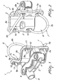
- the reference numeral 1 generally designates a device for fixing a child seat to a frame T of a two-wheeled vehicle or the like.
- the device 1 comprises a plate 2, which can be associated with the frame T, which has at least one first tubular element T1 that is substantially vertical (during the use of such vehicle) and is adapted to support a child seat, not shown in the figures.
- the plate 2 forms a concave region 3 that is designed to make contact with the first tubular element T1.
- the concave region 3 comprises a first wall and a second wall, respectively 3a and 3b, which are mutually inclined so as to form a substantially V-shaped profile and are designed to make contact with the first tubular element T1.
- the plate 2 further has two seats 4 for accommodating the ends of the supporting fork of a child seat, which is not shown in the figures.
- the plate 2 further comprises a device 5 for locking/releasing the supporting fork of the seat, which is of a known type for the person skilled in the art.
- the device 1 further comprises at least one fixing element 6, 7, which forms a substantially open profile that can be associated with the plate 2 in order to define a region 8, 9 for accommodating the first tubular element T1, said region being interposed between the fixing element 6, 7 and the plate 2.
- the device 1 further provides for the presence of removable means for fastening the fixing element 6, 7 to the plate 2 in order to lock the plate 2 with respect to the frame T.
- the fixing element 6, 7 has at least one substantially wire-like portion at the accommodation region 8, 9.
- wire-like references an elongated element in which the dimensions that characterize its cross-section are significantly smaller than its length.
- the fixing element 6, 7 has a substantially wire-like configuration along its entire longitudinal extension.
- the cross-section of the fixing element 6, 7 is substantially circular.
- the fixing element 6, 7 forms a contact region that is designed to contact in an upper region or in a lower region at least one second tubular element T2 of the frame T that is incident to the first tubular element T1.
- the fixing element 6, 7 is substantially C-shaped and has two first substantially straight portions 6a, 7a, which protrude from the respective ends and a second substantially curvilinear portion 6b, 7b, which connects the first portions 6a, 7a and forms the corresponding contact region.
- the first portions 6a, 7a belong to a first plane of arrangement and the second portion 6b, 7b belongs to a second plane of arrangement that is inclined with respect to the first plane of arrangement.
- the device 1 comprises two fixing elements, respectively the first fixing element 6 and the second fixing element 7.
- the fixing elements 6 and 7 can be associated with the plate 2 in order to form respectively a first accommodation region 8 and a second accommodation region 9 for the first tubular element T1, said regions being interposed between the plate 2 and the corresponding fixing element 6, 7.
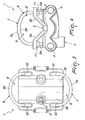
- At least one of the fixing elements 6, 7, preferably both, is substantially C-shaped and has two corresponding first portions 6a, 7a and the corresponding second portion 6b, 7b.
- the first and second fixing elements 6 and 7 have corresponding contact regions that make contact, respectively, with the upper part of the second tubular element T2 and the lower part of a third tubular element T3, which also is incident to the first tubular element T1, proximate to the corresponding regions for connection to the first tubular element T1.
- the action of the fastening means thus makes the fixing elements 6 and 7 apply to the frame T a pair of forces that mutually converge and are adapted to ensure the fixing of the plate 2 to the frame T.
- each one of the fixing elements 6 and 7 forms a respective contact region designed to make contact, in an upper region, respectively with the second tubular element T2 and with the third tubular element T3.
- the locking of the plate 2 with respect to the frame T is further ensured by the contact, by gravity, of the fixing elements 6 and 7 respectively on the second and third tubular elements T2 and T3.
- the fixing elements 6 and 7 can thus be oriented with respect to the plate 2 according to the particular requirements of the situation, i.e., depending on the particular shape of the frame T, so as to ensure locking of the plate 2 to the frame T in the safest possible manner.
- the device 1 comprises means for adjusting the position of the fixing element 6, 7 with respect to the plate 2.
- the adjustment means comprise at least a pair of elongated slots 10, which are formed on the plate 2 and in which it is possible to insert the ends of the fixing element 6, 7, and comprise detachable means for locking such ends on the plate 2, which can be arranged along the slots 10.
- the means for locking the ends of the fixing element 6, 7 with respect to the plate 2 coincide with the means for fastening the corresponding fixing elements to the plate 2.
- the fastening means are constituted by threaded elements 11 of a known type for the person skilled in the art, which engage the ends of the fixing element 6, 7 on the opposite side of the plate 2 with respect to the region 8, 9 for accommodating the first tubular element T1.
- the means for fastening the fixing element 6, 7 to the plate 2 are therefore simplified significantly with respect to known fixing devices, since they are partially integrated within the fixing element itself, the end part of the first portions 6a, 7a being threaded.
- the slots 10 lie along an adjustment direction that is oriented so as to be substantially parallel, with the plate 2 rested on the first tubular element T1, to the longitudinal extension of the first tubular element T1.
- the arrangement of the threaded elements 11 along the slots 10 thus allows to adjust the position of the fixing element 6, 7 with respect to the frame T and more particularly with respect to its tubular elements that are incident to the first tubular element T1, so as to ensure safe fixing of the plate 2 regardless of the shape of the frame T.
- the adjustment means comprise a first pair of slots 10 and a second pair of slots 10, within which it is possible to insert respectively the ends of the first fixing element 6 and the ends of the second fixing element 7.
- the removable locking means comprise first and second means for locking respectively the ends of the first and second fixing elements 6 and 7 to the plate 2.
- the fixing elements 6 and 7 are positioned with respect to the plate 2.
- each fixing element 6, 7 is oriented with respect to the plate 2 and is arranged along the corresponding slots 10, depending on the shape of the frame T, so that the corresponding second portions 6b and 7b can enter the free regions of the frame T and so that the corresponding contact regions make contact, in an upper or lower region, with the second and third tubular elements T2 and T3.
- the fixing elements 6 and 7 are then locked in the corresponding positions by means of the corresponding threaded elements 11.
- the progressive tightening of the threaded elements 11 entails a reduction of the extent of the accommodation regions 8 and 9 and therefore an increase in the adhesion of the plate 2 to the first tubular element T1 due to the higher pressure applied by the fixing elements 6 and 7 to the frame T.
- the device 1 can be easily disassembled from the frame T and applied to a different vehicle by performing again the operations described above, i.e., by repositioning the fixing elements 6 and 7 with respect to the plate 2.
- the described invention achieves the proposed aim and objects, and in particular the fact is stressed that the particular shape of the fixing elements allows their easy application to any type of two-wheeled vehicle, regardless of the particular shape of the corresponding frame, at the same time ensuring safe and reliable support of the seat.
- the device according to the invention is therefore characterized by high flexibility in use.
Claims (8)
- Vorrichtung (1) zum Befestigen eines Kindersitzes an den Rahmen (T) eines zweirädrigen Fahrzeugs, wobei der Rahmen (T) mindestens ein erstes, im Wesentlichen vertikales rohrförmiges Element (T1) besitzt, aufweisend:- eine Platte (2), die mit dem ersten rohrförmigen Element (T1) verbunden werden kann und angepasst ist, einen Kindersitz zu tragen;- mindestens ein Befestigungselement (6, 7), das ein im Wesentlichen offenes Profil bildet, welches mit der Platte (2) verbunden werden kann, um einen Bereich (8, 9) zum Aufnehmen des ersten rohrförmigen Elements (T1), das zwischen das Befestigungselement (6, 7) und die Platte (2) eingefügt wird, zu bilden, wobei eine entfernbare Einrichtung zum Montieren des Befestigungselements (6, 7) an der Platte (2) bereitgestellt wird, um die Platte (2) in Bezug auf den Rahmen (T) zu arretieren; wobei das Befestigungselement (6, 7) mindestens einen im Wesentlichen drahtähnlichen Abschnitt am Aufnahmebereich (8, 9) besitzt und ein Paar erste, im Wesentlichen gerade Abschnitte (6a, 7a), die von den entsprechenden Enden aus verlaufen, und einen zweiten, im Wesentlichen krummlinigen Abschnitt (6b, 7b), der die ersten Abschnitte (6a, 7a) verbindet, besitzt, dadurch gekennzeichnet, dass das Befestigungselement (6, 7) mindestens einen Kontaktbereich bildet, der ausgebildet ist, in einem oberen oder unteren Bereich mit mindestens einem zweiten rohrförmigen Element (T2) des Rahmens (T), das auf das erste rohrförmige Element (T1) trifft, Kontakt herzustellen, wobei der Kontaktbereich durch den zweiten Abschnitt (6b, 7b) festgelegt wird, und dadurch, dass die ersten Abschnitte (6a, 7a) zu einer ersten Anordnungsebene gehören und dass der zweite Abschnitt zu einer zweiten Anordnungsebene gehört, die in Bezug auf die erste Anordnungsebene geneigt ist.
- Vorrichtung (1) nach Anspruch 1, dadurch gekennzeichnet, dass sie eine Einrichtung zum Verstellen der Position des Befestigungselements (6, 7) in Bezug auf die Platte (2) aufweist.
- Vorrichtung (1) nach Anspruch 2, dadurch gekennzeichnet, dass die Verstelleinrichtung mindestens ein Paar längliche Schlitze (10), die in der Platte (2) gebildet werden, aufweist, wobei die Enden des Befestigungselements (6, 7) in die Schlitze (10) einsteckbar sind, wobei entfernbare Einrichtungen zum Arretieren der Enden an der Platte (2), die entlang den Schlitzen (10) positioniert werden können, bereitgestellt werden.
- Vorrichtung (1) nach Anspruch 3, dadurch gekennzeichnet, dass die Schlitze (10) längs einer Verstellrichtung liegen, die, wenn die Platte (2) an dem ersten rohrförmigen Element (T1) anliegt, im Wesentlichen parallel zur Längserstreckung des ersten rohrförmigen Elements (T1) verläuft.
- Vorrichtung (1) nach Anspruch 3 oder 4, dadurch gekennzeichnet, dass die Arretiereinrichtung mit der Montiereinrichtung zusammenfällt.
- Vorrichtung (1) nach einem oder mehr der vorangegangenen Ansprüche, dadurch gekennzeichnet, dass sie mindestens zwei der Befestigungselemente (6, 7) aufweist, ein erstes Befestigungselement (6) bzw. ein zweites Befestigungselement (7).
- Vorrichtung (1) nach einem oder mehr der vorangegangenen Ansprüche, dadurch gekennzeichnet, dass die Platte (2) einen konkaven Abschnitt (3) bildet, der ausgebildet ist, mit dem ersten rohrförmigen Element (T1) Kontakt herzustellen.
- Vorrichtung (1) nach Anspruch 7, dadurch gekennzeichnet, dass der konkave Abschnitt (3) eine erste Wand (3a) und eine zweite Wand (3b) aufweist, die zueinander so geneigt sind, dass sie ein im Wesentlichen V-förmiges Profil bilden, und ausgebildet sind, mit dem ersten rohrförmigen Element (T1) Kontakt herzustellen.
Priority Applications (2)
| Application Number | Priority Date | Filing Date | Title |
|---|---|---|---|
| EP08425580.1A EP2159139B1 (de) | 2008-08-29 | 2008-08-29 | Vorrichtung zum Befestigen eines Kindersitzes an den Rahmen eines zweirädrigen Fahrzeugs |
| EP12186894A EP2543577A1 (de) | 2008-08-29 | 2008-08-29 | Vorrichtung zum Befestigen eines Kindersitzes an den Rahmen eines zweirädrigen Fahrzeugs |
Applications Claiming Priority (1)
| Application Number | Priority Date | Filing Date | Title |
|---|---|---|---|
| EP08425580.1A EP2159139B1 (de) | 2008-08-29 | 2008-08-29 | Vorrichtung zum Befestigen eines Kindersitzes an den Rahmen eines zweirädrigen Fahrzeugs |
Related Child Applications (1)
| Application Number | Title | Priority Date | Filing Date |
|---|---|---|---|
| EP12186894.7 Division-Into | 2012-10-01 |
Publications (2)
| Publication Number | Publication Date |
|---|---|
| EP2159139A1 EP2159139A1 (de) | 2010-03-03 |
| EP2159139B1 true EP2159139B1 (de) | 2013-04-24 |
Family
ID=40260496
Family Applications (2)
| Application Number | Title | Priority Date | Filing Date |
|---|---|---|---|
| EP08425580.1A Not-in-force EP2159139B1 (de) | 2008-08-29 | 2008-08-29 | Vorrichtung zum Befestigen eines Kindersitzes an den Rahmen eines zweirädrigen Fahrzeugs |
| EP12186894A Withdrawn EP2543577A1 (de) | 2008-08-29 | 2008-08-29 | Vorrichtung zum Befestigen eines Kindersitzes an den Rahmen eines zweirädrigen Fahrzeugs |
Family Applications After (1)
| Application Number | Title | Priority Date | Filing Date |
|---|---|---|---|
| EP12186894A Withdrawn EP2543577A1 (de) | 2008-08-29 | 2008-08-29 | Vorrichtung zum Befestigen eines Kindersitzes an den Rahmen eines zweirädrigen Fahrzeugs |
Country Status (1)
| Country | Link |
|---|---|
| EP (2) | EP2159139B1 (de) |
Families Citing this family (3)
| Publication number | Priority date | Publication date | Assignee | Title |
|---|---|---|---|---|
| ITMI20120147A1 (it) | 2012-02-03 | 2013-08-04 | Okbaby S R L | Dispositivo di fissaggio per il montaggio di un seggiolino su di un telaio di un ciclo |
| DE102018112408B3 (de) * | 2018-05-24 | 2019-08-29 | Heinze Metall Gmbh | Gurtsystem für einen Fahrradkindersitz |
| CN110949573B (zh) * | 2019-12-04 | 2024-04-12 | 鲨湾科技(上海)有限公司 | 一种儿童座椅及电动车 |
Family Cites Families (7)
| Publication number | Priority date | Publication date | Assignee | Title |
|---|---|---|---|---|
| US2550001A (en) * | 1948-12-10 | 1951-04-24 | Charles A Morton | Adjustable clamp |
| US5927801A (en) * | 1998-02-17 | 1999-07-27 | Miree; Mallory F. | Auxiliary bicycle seat |
| NO310400B1 (no) | 1999-11-03 | 2001-07-02 | Abry Ind Design As | Holdeanordning for bagasjebrett/barnesete for sykkel |
| DE10035429A1 (de) * | 2000-07-20 | 2002-05-16 | Hamax As Kraaker Diameter Y | Haltevorrichtung für einen Fahrrad-Gepäckträger, Fahrrad-Kindersitz oder einen Träger dafür |
| US6561473B1 (en) * | 2001-03-30 | 2003-05-13 | Pirod, Inc. | Universal pipe mounting clamp and assembly |
| US8186636B2 (en) * | 2004-06-07 | 2012-05-29 | Carnevali Jeffrey D | Configurable mounting bracket |
| WO2007111497A1 (en) | 2006-03-29 | 2007-10-04 | Dremefa B.V. | Bicycle child seat mounting assembly |
-
2008
- 2008-08-29 EP EP08425580.1A patent/EP2159139B1/de not_active Not-in-force
- 2008-08-29 EP EP12186894A patent/EP2543577A1/de not_active Withdrawn
Also Published As
| Publication number | Publication date |
|---|---|
| EP2543577A1 (de) | 2013-01-09 |
| EP2159139A1 (de) | 2010-03-03 |
Similar Documents
| Publication | Publication Date | Title |
|---|---|---|
| US8721001B2 (en) | Headrest | |
| US7967336B2 (en) | Wheelchair transport rack for motorcycles and recreational vehicles | |
| CN106536338B (zh) | 自行车车座和锁组件 | |
| EP2159139B1 (de) | Vorrichtung zum Befestigen eines Kindersitzes an den Rahmen eines zweirädrigen Fahrzeugs | |
| EP3303110B1 (de) | Sattel für ein fahrzeug | |
| US6719254B1 (en) | Article holder | |
| TW202103999A (zh) | 具有柔緩性座墊支柱介面之自行車 | |
| US9174699B2 (en) | Bicycle tow device | |
| US20130292438A1 (en) | Adjustable pannier frame | |
| GB2512279A (en) | A mount device | |
| EP1893445B1 (de) | Lastträgerfuss zur befestigung eines lastträgers | |
| US20170297642A1 (en) | Leather bicycle saddle | |
| US10773763B2 (en) | Bicycle kickstand installation adapter and double leg stand comprising same | |
| EP2090503A1 (de) | Hilfsvorrichtung einer Motorrad-Fußraste | |
| US10843754B2 (en) | Can-Am Spyder F3® seat back/trunk extension | |
| JP6080748B2 (ja) | 子供乗せ装置の取付構造および二輪車 | |
| WO2018037247A1 (en) | Lifting bracket | |
| US7367620B1 (en) | Bicycle seat and associated methods | |
| NL2004866C2 (en) | Detachable seating for a bike. | |
| KR101810848B1 (ko) | 각도조절수단이 구비된 자전거 | |
| EP3231695B1 (de) | Lederfahrradsattel | |
| KR20160098728A (ko) | 탈부착 가능한 시트 완충장치 | |
| KR200292547Y1 (ko) | 스쿠터 | |
| JP4644029B2 (ja) | フットレストの取付け構造 | |
| US20150375819A1 (en) | Motorcycle/ATV Driver Backrest Passenger Handle Bar |
Legal Events
| Date | Code | Title | Description |
|---|---|---|---|
| PUAI | Public reference made under article 153(3) epc to a published international application that has entered the european phase |
Free format text: ORIGINAL CODE: 0009012 |
|
| AK | Designated contracting states |
Kind code of ref document: A1 Designated state(s): AT BE BG CH CY CZ DE DK EE ES FI FR GB GR HR HU IE IS IT LI LT LU LV MC MT NL NO PL PT RO SE SI SK TR |
|
| AX | Request for extension of the european patent |
Extension state: AL BA MK RS |
|
| 17P | Request for examination filed |
Effective date: 20100903 |
|
| 17Q | First examination report despatched |
Effective date: 20101001 |
|
| AKX | Designation fees paid |
Designated state(s): AT BE BG CH CY CZ DE DK EE ES FI FR GB GR HR HU IE IS IT LI LT LU LV MC MT NL NO PL PT RO SE SI SK TR |
|
| GRAP | Despatch of communication of intention to grant a patent |
Free format text: ORIGINAL CODE: EPIDOSNIGR1 |
|
| GRAS | Grant fee paid |
Free format text: ORIGINAL CODE: EPIDOSNIGR3 |
|
| GRAA | (expected) grant |
Free format text: ORIGINAL CODE: 0009210 |
|
| AK | Designated contracting states |
Kind code of ref document: B1 Designated state(s): AT BE BG CH CY CZ DE DK EE ES FI FR GB GR HR HU IE IS IT LI LT LU LV MC MT NL NO PL PT RO SE SI SK TR |
|
| REG | Reference to a national code |
Ref country code: GB Ref legal event code: FG4D |
|
| REG | Reference to a national code |
Ref country code: CH Ref legal event code: EP |
|
| REG | Reference to a national code |
Ref country code: AT Ref legal event code: REF Ref document number: 608451 Country of ref document: AT Kind code of ref document: T Effective date: 20130515 |
|
| REG | Reference to a national code |
Ref country code: IE Ref legal event code: FG4D |
|
| REG | Reference to a national code |
Ref country code: DE Ref legal event code: R096 Ref document number: 602008024044 Country of ref document: DE Effective date: 20130620 |
|
| REG | Reference to a national code |
Ref country code: AT Ref legal event code: MK05 Ref document number: 608451 Country of ref document: AT Kind code of ref document: T Effective date: 20130424 |
|
| REG | Reference to a national code |
Ref country code: LT Ref legal event code: MG4D |
|
| REG | Reference to a national code |
Ref country code: NL Ref legal event code: VDEP Effective date: 20130424 |
|
| PG25 | Lapsed in a contracting state [announced via postgrant information from national office to epo] |
Ref country code: LT Free format text: LAPSE BECAUSE OF FAILURE TO SUBMIT A TRANSLATION OF THE DESCRIPTION OR TO PAY THE FEE WITHIN THE PRESCRIBED TIME-LIMIT Effective date: 20130424 Ref country code: AT Free format text: LAPSE BECAUSE OF FAILURE TO SUBMIT A TRANSLATION OF THE DESCRIPTION OR TO PAY THE FEE WITHIN THE PRESCRIBED TIME-LIMIT Effective date: 20130424 Ref country code: PT Free format text: LAPSE BECAUSE OF FAILURE TO SUBMIT A TRANSLATION OF THE DESCRIPTION OR TO PAY THE FEE WITHIN THE PRESCRIBED TIME-LIMIT Effective date: 20130826 Ref country code: SE Free format text: LAPSE BECAUSE OF FAILURE TO SUBMIT A TRANSLATION OF THE DESCRIPTION OR TO PAY THE FEE WITHIN THE PRESCRIBED TIME-LIMIT Effective date: 20130424 Ref country code: NO Free format text: LAPSE BECAUSE OF FAILURE TO SUBMIT A TRANSLATION OF THE DESCRIPTION OR TO PAY THE FEE WITHIN THE PRESCRIBED TIME-LIMIT Effective date: 20130724 Ref country code: SI Free format text: LAPSE BECAUSE OF FAILURE TO SUBMIT A TRANSLATION OF THE DESCRIPTION OR TO PAY THE FEE WITHIN THE PRESCRIBED TIME-LIMIT Effective date: 20130424 Ref country code: FI Free format text: LAPSE BECAUSE OF FAILURE TO SUBMIT A TRANSLATION OF THE DESCRIPTION OR TO PAY THE FEE WITHIN THE PRESCRIBED TIME-LIMIT Effective date: 20130424 Ref country code: GR Free format text: LAPSE BECAUSE OF FAILURE TO SUBMIT A TRANSLATION OF THE DESCRIPTION OR TO PAY THE FEE WITHIN THE PRESCRIBED TIME-LIMIT Effective date: 20130725 Ref country code: ES Free format text: LAPSE BECAUSE OF FAILURE TO SUBMIT A TRANSLATION OF THE DESCRIPTION OR TO PAY THE FEE WITHIN THE PRESCRIBED TIME-LIMIT Effective date: 20130804 Ref country code: BE Free format text: LAPSE BECAUSE OF FAILURE TO SUBMIT A TRANSLATION OF THE DESCRIPTION OR TO PAY THE FEE WITHIN THE PRESCRIBED TIME-LIMIT Effective date: 20130424 Ref country code: IS Free format text: LAPSE BECAUSE OF FAILURE TO SUBMIT A TRANSLATION OF THE DESCRIPTION OR TO PAY THE FEE WITHIN THE PRESCRIBED TIME-LIMIT Effective date: 20130824 |
|
| PG25 | Lapsed in a contracting state [announced via postgrant information from national office to epo] |
Ref country code: CY Free format text: LAPSE BECAUSE OF FAILURE TO SUBMIT A TRANSLATION OF THE DESCRIPTION OR TO PAY THE FEE WITHIN THE PRESCRIBED TIME-LIMIT Effective date: 20130424 Ref country code: HR Free format text: LAPSE BECAUSE OF FAILURE TO SUBMIT A TRANSLATION OF THE DESCRIPTION OR TO PAY THE FEE WITHIN THE PRESCRIBED TIME-LIMIT Effective date: 20130424 Ref country code: BG Free format text: LAPSE BECAUSE OF FAILURE TO SUBMIT A TRANSLATION OF THE DESCRIPTION OR TO PAY THE FEE WITHIN THE PRESCRIBED TIME-LIMIT Effective date: 20130724 Ref country code: PL Free format text: LAPSE BECAUSE OF FAILURE TO SUBMIT A TRANSLATION OF THE DESCRIPTION OR TO PAY THE FEE WITHIN THE PRESCRIBED TIME-LIMIT Effective date: 20130424 Ref country code: LV Free format text: LAPSE BECAUSE OF FAILURE TO SUBMIT A TRANSLATION OF THE DESCRIPTION OR TO PAY THE FEE WITHIN THE PRESCRIBED TIME-LIMIT Effective date: 20130424 |
|
| PG25 | Lapsed in a contracting state [announced via postgrant information from national office to epo] |
Ref country code: DK Free format text: LAPSE BECAUSE OF FAILURE TO SUBMIT A TRANSLATION OF THE DESCRIPTION OR TO PAY THE FEE WITHIN THE PRESCRIBED TIME-LIMIT Effective date: 20130424 Ref country code: SK Free format text: LAPSE BECAUSE OF FAILURE TO SUBMIT A TRANSLATION OF THE DESCRIPTION OR TO PAY THE FEE WITHIN THE PRESCRIBED TIME-LIMIT Effective date: 20130424 Ref country code: EE Free format text: LAPSE BECAUSE OF FAILURE TO SUBMIT A TRANSLATION OF THE DESCRIPTION OR TO PAY THE FEE WITHIN THE PRESCRIBED TIME-LIMIT Effective date: 20130424 Ref country code: CZ Free format text: LAPSE BECAUSE OF FAILURE TO SUBMIT A TRANSLATION OF THE DESCRIPTION OR TO PAY THE FEE WITHIN THE PRESCRIBED TIME-LIMIT Effective date: 20130424 |
|
| PG25 | Lapsed in a contracting state [announced via postgrant information from national office to epo] |
Ref country code: NL Free format text: LAPSE BECAUSE OF FAILURE TO SUBMIT A TRANSLATION OF THE DESCRIPTION OR TO PAY THE FEE WITHIN THE PRESCRIBED TIME-LIMIT Effective date: 20130424 Ref country code: RO Free format text: LAPSE BECAUSE OF FAILURE TO SUBMIT A TRANSLATION OF THE DESCRIPTION OR TO PAY THE FEE WITHIN THE PRESCRIBED TIME-LIMIT Effective date: 20130424 |
|
| PLBE | No opposition filed within time limit |
Free format text: ORIGINAL CODE: 0009261 |
|
| STAA | Information on the status of an ep patent application or granted ep patent |
Free format text: STATUS: NO OPPOSITION FILED WITHIN TIME LIMIT |
|
| REG | Reference to a national code |
Ref country code: CH Ref legal event code: PL |
|
| 26N | No opposition filed |
Effective date: 20140127 |
|
| PG25 | Lapsed in a contracting state [announced via postgrant information from national office to epo] |
Ref country code: MC Free format text: LAPSE BECAUSE OF FAILURE TO SUBMIT A TRANSLATION OF THE DESCRIPTION OR TO PAY THE FEE WITHIN THE PRESCRIBED TIME-LIMIT Effective date: 20130424 Ref country code: LI Free format text: LAPSE BECAUSE OF NON-PAYMENT OF DUE FEES Effective date: 20130831 Ref country code: CH Free format text: LAPSE BECAUSE OF NON-PAYMENT OF DUE FEES Effective date: 20130831 |
|
| REG | Reference to a national code |
Ref country code: DE Ref legal event code: R097 Ref document number: 602008024044 Country of ref document: DE Effective date: 20140127 |
|
| REG | Reference to a national code |
Ref country code: IE Ref legal event code: MM4A |
|
| PG25 | Lapsed in a contracting state [announced via postgrant information from national office to epo] |
Ref country code: IE Free format text: LAPSE BECAUSE OF NON-PAYMENT OF DUE FEES Effective date: 20130829 |
|
| PG25 | Lapsed in a contracting state [announced via postgrant information from national office to epo] |
Ref country code: TR Free format text: LAPSE BECAUSE OF FAILURE TO SUBMIT A TRANSLATION OF THE DESCRIPTION OR TO PAY THE FEE WITHIN THE PRESCRIBED TIME-LIMIT Effective date: 20130424 Ref country code: MT Free format text: LAPSE BECAUSE OF FAILURE TO SUBMIT A TRANSLATION OF THE DESCRIPTION OR TO PAY THE FEE WITHIN THE PRESCRIBED TIME-LIMIT Effective date: 20130424 |
|
| PG25 | Lapsed in a contracting state [announced via postgrant information from national office to epo] |
Ref country code: HU Free format text: LAPSE BECAUSE OF FAILURE TO SUBMIT A TRANSLATION OF THE DESCRIPTION OR TO PAY THE FEE WITHIN THE PRESCRIBED TIME-LIMIT; INVALID AB INITIO Effective date: 20080829 Ref country code: LU Free format text: LAPSE BECAUSE OF NON-PAYMENT OF DUE FEES Effective date: 20130829 |
|
| REG | Reference to a national code |
Ref country code: FR Ref legal event code: PLFP Year of fee payment: 8 |
|
| PGFP | Annual fee paid to national office [announced via postgrant information from national office to epo] |
Ref country code: DE Payment date: 20150827 Year of fee payment: 8 Ref country code: GB Payment date: 20150827 Year of fee payment: 8 |
|
| PGFP | Annual fee paid to national office [announced via postgrant information from national office to epo] |
Ref country code: FR Payment date: 20150817 Year of fee payment: 8 |
|
| PGFP | Annual fee paid to national office [announced via postgrant information from national office to epo] |
Ref country code: IT Payment date: 20150825 Year of fee payment: 8 |
|
| REG | Reference to a national code |
Ref country code: DE Ref legal event code: R119 Ref document number: 602008024044 Country of ref document: DE |
|
| GBPC | Gb: european patent ceased through non-payment of renewal fee |
Effective date: 20160829 |
|
| REG | Reference to a national code |
Ref country code: FR Ref legal event code: ST Effective date: 20170428 |
|
| PG25 | Lapsed in a contracting state [announced via postgrant information from national office to epo] |
Ref country code: FR Free format text: LAPSE BECAUSE OF NON-PAYMENT OF DUE FEES Effective date: 20160831 Ref country code: GB Free format text: LAPSE BECAUSE OF NON-PAYMENT OF DUE FEES Effective date: 20160829 Ref country code: DE Free format text: LAPSE BECAUSE OF NON-PAYMENT OF DUE FEES Effective date: 20170301 |
|
| PG25 | Lapsed in a contracting state [announced via postgrant information from national office to epo] |
Ref country code: IT Free format text: LAPSE BECAUSE OF NON-PAYMENT OF DUE FEES Effective date: 20160829 |