EP2158603B1 - Verfahren zur herstellung von integrierten mems-schaltungen - Google Patents
Verfahren zur herstellung von integrierten mems-schaltungen Download PDFInfo
- Publication number
- EP2158603B1 EP2158603B1 EP08733380A EP08733380A EP2158603B1 EP 2158603 B1 EP2158603 B1 EP 2158603B1 EP 08733380 A EP08733380 A EP 08733380A EP 08733380 A EP08733380 A EP 08733380A EP 2158603 B1 EP2158603 B1 EP 2158603B1
- Authority
- EP
- European Patent Office
- Prior art keywords
- wafer
- backside
- nozzle
- mems
- holding means
- Prior art date
- Legal status (The legal status is an assumption and is not a legal conclusion. Google has not performed a legal analysis and makes no representation as to the accuracy of the status listed.)
- Not-in-force
Links
- 238000004519 manufacturing process Methods 0.000 title claims description 26
- 239000000463 material Substances 0.000 claims abstract description 39
- 229920000642 polymer Polymers 0.000 claims description 55
- 238000000034 method Methods 0.000 claims description 51
- 238000000576 coating method Methods 0.000 claims description 44
- 239000011248 coating agent Substances 0.000 claims description 43
- 230000000712 assembly Effects 0.000 claims description 22
- 238000000429 assembly Methods 0.000 claims description 22
- 238000005530 etching Methods 0.000 claims description 16
- 239000004205 dimethyl polysiloxane Substances 0.000 claims description 13
- 229920000435 poly(dimethylsiloxane) Polymers 0.000 claims description 13
- 230000001590 oxidative effect Effects 0.000 claims description 10
- 239000002390 adhesive tape Substances 0.000 claims description 9
- -1 siloxanes Chemical class 0.000 claims description 9
- 239000004698 Polyethylene Substances 0.000 claims description 3
- 229920000573 polyethylene Polymers 0.000 claims description 3
- 229920000098 polyolefin Polymers 0.000 claims description 3
- 239000000919 ceramic Substances 0.000 abstract description 2
- 239000010410 layer Substances 0.000 description 47
- 238000004380 ashing Methods 0.000 description 25
- 229920002120 photoresistant polymer Polymers 0.000 description 23
- 238000012545 processing Methods 0.000 description 21
- 229920001600 hydrophobic polymer Polymers 0.000 description 19
- 230000002209 hydrophobic effect Effects 0.000 description 17
- 230000008569 process Effects 0.000 description 17
- XUIMIQQOPSSXEZ-UHFFFAOYSA-N Silicon Chemical compound [Si] XUIMIQQOPSSXEZ-UHFFFAOYSA-N 0.000 description 16
- 229910052710 silicon Inorganic materials 0.000 description 16
- 239000010703 silicon Substances 0.000 description 16
- 239000011241 protective layer Substances 0.000 description 14
- 238000007641 inkjet printing Methods 0.000 description 11
- 238000000151 deposition Methods 0.000 description 10
- 239000000758 substrate Substances 0.000 description 10
- VYPSYNLAJGMNEJ-UHFFFAOYSA-N Silicium dioxide Chemical compound O=[Si]=O VYPSYNLAJGMNEJ-UHFFFAOYSA-N 0.000 description 9
- 230000008901 benefit Effects 0.000 description 9
- 230000008021 deposition Effects 0.000 description 9
- 239000011521 glass Substances 0.000 description 8
- 238000007639 printing Methods 0.000 description 7
- 230000003068 static effect Effects 0.000 description 7
- 238000010276 construction Methods 0.000 description 6
- 101000869523 Homo sapiens Phosphatidylinositide phosphatase SAC2 Proteins 0.000 description 5
- 101000869517 Homo sapiens Phosphatidylinositol-3-phosphatase SAC1 Proteins 0.000 description 5
- 102100032287 Phosphatidylinositide phosphatase SAC2 Human genes 0.000 description 5
- 102100032286 Phosphatidylinositol-3-phosphatase SAC1 Human genes 0.000 description 5
- 229910052581 Si3N4 Inorganic materials 0.000 description 5
- 230000001070 adhesive effect Effects 0.000 description 5
- 239000007789 gas Substances 0.000 description 5
- HQVNEWCFYHHQES-UHFFFAOYSA-N silicon nitride Chemical compound N12[Si]34N5[Si]62N3[Si]51N64 HQVNEWCFYHHQES-UHFFFAOYSA-N 0.000 description 5
- 239000000853 adhesive Substances 0.000 description 4
- 238000005516 engineering process Methods 0.000 description 4
- 235000012239 silicon dioxide Nutrition 0.000 description 4
- 239000000377 silicon dioxide Substances 0.000 description 4
- QVGXLLKOCUKJST-UHFFFAOYSA-N atomic oxygen Chemical compound [O] QVGXLLKOCUKJST-UHFFFAOYSA-N 0.000 description 3
- 239000001301 oxygen Substances 0.000 description 3
- 229910052760 oxygen Inorganic materials 0.000 description 3
- 238000000926 separation method Methods 0.000 description 3
- 230000009471 action Effects 0.000 description 2
- 229910010293 ceramic material Inorganic materials 0.000 description 2
- 235000009508 confectionery Nutrition 0.000 description 2
- 238000012986 modification Methods 0.000 description 2
- 230000004048 modification Effects 0.000 description 2
- 239000011253 protective coating Substances 0.000 description 2
- 238000007789 sealing Methods 0.000 description 2
- 229910017083 AlN Inorganic materials 0.000 description 1
- PIGFYZPCRLYGLF-UHFFFAOYSA-N Aluminum nitride Chemical compound [Al]#N PIGFYZPCRLYGLF-UHFFFAOYSA-N 0.000 description 1
- JBRZTFJDHDCESZ-UHFFFAOYSA-N AsGa Chemical compound [As]#[Ga] JBRZTFJDHDCESZ-UHFFFAOYSA-N 0.000 description 1
- 239000004215 Carbon black (E152) Substances 0.000 description 1
- 229910001218 Gallium arsenide Inorganic materials 0.000 description 1
- ATJFFYVFTNAWJD-UHFFFAOYSA-N Tin Chemical compound [Sn] ATJFFYVFTNAWJD-UHFFFAOYSA-N 0.000 description 1
- 230000004913 activation Effects 0.000 description 1
- PNEYBMLMFCGWSK-UHFFFAOYSA-N aluminium oxide Inorganic materials [O-2].[O-2].[O-2].[Al+3].[Al+3] PNEYBMLMFCGWSK-UHFFFAOYSA-N 0.000 description 1
- 238000005452 bending Methods 0.000 description 1
- 229910052681 coesite Inorganic materials 0.000 description 1
- 238000004891 communication Methods 0.000 description 1
- 229910052906 cristobalite Inorganic materials 0.000 description 1
- 239000013078 crystal Substances 0.000 description 1
- 238000000708 deep reactive-ion etching Methods 0.000 description 1
- 238000013461 design Methods 0.000 description 1
- 230000005686 electrostatic field Effects 0.000 description 1
- 238000011049 filling Methods 0.000 description 1
- 239000012530 fluid Substances 0.000 description 1
- 238000000227 grinding Methods 0.000 description 1
- 229930195733 hydrocarbon Natural products 0.000 description 1
- 150000002430 hydrocarbons Chemical class 0.000 description 1
- 230000005660 hydrophilic surface Effects 0.000 description 1
- 238000009413 insulation Methods 0.000 description 1
- 238000007648 laser printing Methods 0.000 description 1
- 230000007774 longterm Effects 0.000 description 1
- 238000012423 maintenance Methods 0.000 description 1
- 239000011159 matrix material Substances 0.000 description 1
- 239000000203 mixture Substances 0.000 description 1
- 238000007645 offset printing Methods 0.000 description 1
- 238000001020 plasma etching Methods 0.000 description 1
- 238000000623 plasma-assisted chemical vapour deposition Methods 0.000 description 1
- 239000013047 polymeric layer Substances 0.000 description 1
- 230000037452 priming Effects 0.000 description 1
- 230000002035 prolonged effect Effects 0.000 description 1
- 230000001681 protective effect Effects 0.000 description 1
- 239000010453 quartz Substances 0.000 description 1
- 239000004065 semiconductor Substances 0.000 description 1
- 238000004904 shortening Methods 0.000 description 1
- 229910052682 stishovite Inorganic materials 0.000 description 1
- 238000000859 sublimation Methods 0.000 description 1
- 230000008022 sublimation Effects 0.000 description 1
- 238000012546 transfer Methods 0.000 description 1
- 229910052905 tridymite Inorganic materials 0.000 description 1
Images


Classifications
-
- B—PERFORMING OPERATIONS; TRANSPORTING
- B41—PRINTING; LINING MACHINES; TYPEWRITERS; STAMPS
- B41J—TYPEWRITERS; SELECTIVE PRINTING MECHANISMS, i.e. MECHANISMS PRINTING OTHERWISE THAN FROM A FORME; CORRECTION OF TYPOGRAPHICAL ERRORS
- B41J2/00—Typewriters or selective printing mechanisms characterised by the printing or marking process for which they are designed
- B41J2/005—Typewriters or selective printing mechanisms characterised by the printing or marking process for which they are designed characterised by bringing liquid or particles selectively into contact with a printing material
- B41J2/01—Ink jet
- B41J2/135—Nozzles
- B41J2/14—Structure thereof only for on-demand ink jet heads
- B41J2/14016—Structure of bubble jet print heads
- B41J2/14032—Structure of the pressure chamber
- B41J2/1404—Geometrical characteristics
-
- B—PERFORMING OPERATIONS; TRANSPORTING
- B41—PRINTING; LINING MACHINES; TYPEWRITERS; STAMPS
- B41J—TYPEWRITERS; SELECTIVE PRINTING MECHANISMS, i.e. MECHANISMS PRINTING OTHERWISE THAN FROM A FORME; CORRECTION OF TYPOGRAPHICAL ERRORS
- B41J2/00—Typewriters or selective printing mechanisms characterised by the printing or marking process for which they are designed
- B41J2/005—Typewriters or selective printing mechanisms characterised by the printing or marking process for which they are designed characterised by bringing liquid or particles selectively into contact with a printing material
- B41J2/01—Ink jet
- B41J2/135—Nozzles
- B41J2/16—Production of nozzles
- B41J2/1601—Production of bubble jet print heads
-
- B—PERFORMING OPERATIONS; TRANSPORTING
- B41—PRINTING; LINING MACHINES; TYPEWRITERS; STAMPS
- B41J—TYPEWRITERS; SELECTIVE PRINTING MECHANISMS, i.e. MECHANISMS PRINTING OTHERWISE THAN FROM A FORME; CORRECTION OF TYPOGRAPHICAL ERRORS
- B41J2/00—Typewriters or selective printing mechanisms characterised by the printing or marking process for which they are designed
- B41J2/005—Typewriters or selective printing mechanisms characterised by the printing or marking process for which they are designed characterised by bringing liquid or particles selectively into contact with a printing material
- B41J2/01—Ink jet
- B41J2/135—Nozzles
- B41J2/16—Production of nozzles
- B41J2/1606—Coating the nozzle area or the ink chamber
-
- B—PERFORMING OPERATIONS; TRANSPORTING
- B41—PRINTING; LINING MACHINES; TYPEWRITERS; STAMPS
- B41J—TYPEWRITERS; SELECTIVE PRINTING MECHANISMS, i.e. MECHANISMS PRINTING OTHERWISE THAN FROM A FORME; CORRECTION OF TYPOGRAPHICAL ERRORS
- B41J2/00—Typewriters or selective printing mechanisms characterised by the printing or marking process for which they are designed
- B41J2/005—Typewriters or selective printing mechanisms characterised by the printing or marking process for which they are designed characterised by bringing liquid or particles selectively into contact with a printing material
- B41J2/01—Ink jet
- B41J2/135—Nozzles
- B41J2/16—Production of nozzles
- B41J2/1621—Manufacturing processes
- B41J2/1626—Manufacturing processes etching
- B41J2/1628—Manufacturing processes etching dry etching
-
- B—PERFORMING OPERATIONS; TRANSPORTING
- B41—PRINTING; LINING MACHINES; TYPEWRITERS; STAMPS
- B41J—TYPEWRITERS; SELECTIVE PRINTING MECHANISMS, i.e. MECHANISMS PRINTING OTHERWISE THAN FROM A FORME; CORRECTION OF TYPOGRAPHICAL ERRORS
- B41J2/00—Typewriters or selective printing mechanisms characterised by the printing or marking process for which they are designed
- B41J2/005—Typewriters or selective printing mechanisms characterised by the printing or marking process for which they are designed characterised by bringing liquid or particles selectively into contact with a printing material
- B41J2/01—Ink jet
- B41J2/135—Nozzles
- B41J2/16—Production of nozzles
- B41J2/1621—Manufacturing processes
- B41J2/1631—Manufacturing processes photolithography
-
- B—PERFORMING OPERATIONS; TRANSPORTING
- B41—PRINTING; LINING MACHINES; TYPEWRITERS; STAMPS
- B41J—TYPEWRITERS; SELECTIVE PRINTING MECHANISMS, i.e. MECHANISMS PRINTING OTHERWISE THAN FROM A FORME; CORRECTION OF TYPOGRAPHICAL ERRORS
- B41J2/00—Typewriters or selective printing mechanisms characterised by the printing or marking process for which they are designed
- B41J2/005—Typewriters or selective printing mechanisms characterised by the printing or marking process for which they are designed characterised by bringing liquid or particles selectively into contact with a printing material
- B41J2/01—Ink jet
- B41J2/135—Nozzles
- B41J2/16—Production of nozzles
- B41J2/1621—Manufacturing processes
- B41J2/1635—Manufacturing processes dividing the wafer into individual chips
-
- B—PERFORMING OPERATIONS; TRANSPORTING
- B41—PRINTING; LINING MACHINES; TYPEWRITERS; STAMPS
- B41J—TYPEWRITERS; SELECTIVE PRINTING MECHANISMS, i.e. MECHANISMS PRINTING OTHERWISE THAN FROM A FORME; CORRECTION OF TYPOGRAPHICAL ERRORS
- B41J2/00—Typewriters or selective printing mechanisms characterised by the printing or marking process for which they are designed
- B41J2/005—Typewriters or selective printing mechanisms characterised by the printing or marking process for which they are designed characterised by bringing liquid or particles selectively into contact with a printing material
- B41J2/01—Ink jet
- B41J2/135—Nozzles
- B41J2/16—Production of nozzles
- B41J2/1621—Manufacturing processes
- B41J2/1637—Manufacturing processes molding
- B41J2/1639—Manufacturing processes molding sacrificial molding
-
- B—PERFORMING OPERATIONS; TRANSPORTING
- B41—PRINTING; LINING MACHINES; TYPEWRITERS; STAMPS
- B41J—TYPEWRITERS; SELECTIVE PRINTING MECHANISMS, i.e. MECHANISMS PRINTING OTHERWISE THAN FROM A FORME; CORRECTION OF TYPOGRAPHICAL ERRORS
- B41J2/00—Typewriters or selective printing mechanisms characterised by the printing or marking process for which they are designed
- B41J2/005—Typewriters or selective printing mechanisms characterised by the printing or marking process for which they are designed characterised by bringing liquid or particles selectively into contact with a printing material
- B41J2/01—Ink jet
- B41J2/135—Nozzles
- B41J2/16—Production of nozzles
- B41J2/1621—Manufacturing processes
- B41J2/164—Manufacturing processes thin film formation
- B41J2/1645—Manufacturing processes thin film formation thin film formation by spincoating
-
- B—PERFORMING OPERATIONS; TRANSPORTING
- B41—PRINTING; LINING MACHINES; TYPEWRITERS; STAMPS
- B41J—TYPEWRITERS; SELECTIVE PRINTING MECHANISMS, i.e. MECHANISMS PRINTING OTHERWISE THAN FROM A FORME; CORRECTION OF TYPOGRAPHICAL ERRORS
- B41J2/00—Typewriters or selective printing mechanisms characterised by the printing or marking process for which they are designed
- B41J2/005—Typewriters or selective printing mechanisms characterised by the printing or marking process for which they are designed characterised by bringing liquid or particles selectively into contact with a printing material
- B41J2/01—Ink jet
- B41J2/135—Nozzles
- B41J2/16—Production of nozzles
- B41J2/1621—Manufacturing processes
- B41J2/164—Manufacturing processes thin film formation
- B41J2/1646—Manufacturing processes thin film formation thin film formation by sputtering
-
- B—PERFORMING OPERATIONS; TRANSPORTING
- B41—PRINTING; LINING MACHINES; TYPEWRITERS; STAMPS
- B41J—TYPEWRITERS; SELECTIVE PRINTING MECHANISMS, i.e. MECHANISMS PRINTING OTHERWISE THAN FROM A FORME; CORRECTION OF TYPOGRAPHICAL ERRORS
- B41J2/00—Typewriters or selective printing mechanisms characterised by the printing or marking process for which they are designed
- B41J2/005—Typewriters or selective printing mechanisms characterised by the printing or marking process for which they are designed characterised by bringing liquid or particles selectively into contact with a printing material
- B41J2/01—Ink jet
- B41J2/135—Nozzles
- B41J2/14—Structure thereof only for on-demand ink jet heads
- B41J2002/14459—Matrix arrangement of the pressure chambers
-
- B—PERFORMING OPERATIONS; TRANSPORTING
- B41—PRINTING; LINING MACHINES; TYPEWRITERS; STAMPS
- B41J—TYPEWRITERS; SELECTIVE PRINTING MECHANISMS, i.e. MECHANISMS PRINTING OTHERWISE THAN FROM A FORME; CORRECTION OF TYPOGRAPHICAL ERRORS
- B41J2/00—Typewriters or selective printing mechanisms characterised by the printing or marking process for which they are designed
- B41J2/005—Typewriters or selective printing mechanisms characterised by the printing or marking process for which they are designed characterised by bringing liquid or particles selectively into contact with a printing material
- B41J2/01—Ink jet
- B41J2/135—Nozzles
- B41J2/14—Structure thereof only for on-demand ink jet heads
- B41J2002/14475—Structure thereof only for on-demand ink jet heads characterised by nozzle shapes or number of orifices per chamber
-
- B—PERFORMING OPERATIONS; TRANSPORTING
- B41—PRINTING; LINING MACHINES; TYPEWRITERS; STAMPS
- B41J—TYPEWRITERS; SELECTIVE PRINTING MECHANISMS, i.e. MECHANISMS PRINTING OTHERWISE THAN FROM A FORME; CORRECTION OF TYPOGRAPHICAL ERRORS
- B41J2202/00—Embodiments of or processes related to ink-jet or thermal heads
- B41J2202/01—Embodiments of or processes related to ink-jet heads
- B41J2202/15—Moving nozzle or nozzle plate
-
- Y—GENERAL TAGGING OF NEW TECHNOLOGICAL DEVELOPMENTS; GENERAL TAGGING OF CROSS-SECTIONAL TECHNOLOGIES SPANNING OVER SEVERAL SECTIONS OF THE IPC; TECHNICAL SUBJECTS COVERED BY FORMER USPC CROSS-REFERENCE ART COLLECTIONS [XRACs] AND DIGESTS
- Y10—TECHNICAL SUBJECTS COVERED BY FORMER USPC
- Y10T—TECHNICAL SUBJECTS COVERED BY FORMER US CLASSIFICATION
- Y10T29/00—Metal working
- Y10T29/49—Method of mechanical manufacture
- Y10T29/49401—Fluid pattern dispersing device making, e.g., ink jet
Definitions
- the present invention relates to the field of printers and particularly inkjet printheads. It has been developed primarily to improve fabrications methods, print quality and reliability in high resolution printheads.
- Ink Jet printers themselves come in many different types.
- the utilization of a continuous stream of ink in ink jet printing appears to date back to at least 1929 wherein US Patent No. 1941001 by Hansell discloses a simple form of continuous stream electro-static ink jet printing.
- US Patent 3596275 by Sweet also discloses a process of a continuous ink jet printing including the step wherein the ink jet stream is modulated by a high frequency electro-static field so as to cause drop separation. This technique is still utilized by several manufacturers including Elmjet and Scitex (see also US Patent No. 3373437 by Sweet et al )
- Piezoelectric ink jet printers are also one form of commonly utilized inkjet printing device. Piezoelectric systems are disclosed by Kyser et. al. in US Patent No. 3946398 (1970 ) which utilizes a diaphragm mode of operation, by Zolten in US Patent 3683212 (1970 ) which discloses a squeeze mode of operation of a piezoelectric crystal, Stemme in US Patent No. 3747120 (1972 ) discloses a bend mode of piezoelectric operation, Howkins in US Patent No. 4459601 discloses a piezoelectric push mode actuation of the ink jet stream and Fischbeck in US 4584590 which discloses a shear mode type of piezoelectric transducer element.
- the ink jet printing techniques include those disclosed by Endo et al in GB 2007162 (1979 ) and Vaughtet al in US Patent 4490728 . Both the aforementioned references disclosed ink jet printing techniques that rely upon the activation of an electrothermal actuator which results in the creation of a bubble in a constricted space, such as a nozzle, which thereby causes the ejection of ink from an aperture connected to the confined space onto a relevant print media.
- Printing devices utilizing the electro-thermal actuator are manufactured by manufacturers such as Canon and Hewlett Packard.
- a printing technology should have a number of desirable attributes. These include inexpensive construction and operation, high speed operation, safe and continuous long term operation etc. Each technology may have its own advantages and disadvantages in the areas of cost, speed, quality, reliability, power usage, simplicity of construction operation, durability and consumables.
- inkjet printheads are normally constructed utilizing micro-electromechanical systems (MEMS) techniques. As such, they tend to rely upon standard integrated circuit construction/fabrication techniques of depositing planar layers on a silicon wafer and etching certain portions of the planar layers. Within silicon circuit fabrication technology, certain techniques are better known than others. For example, the techniques associated with the creation of CMOS circuits are likely to be more readily used than those associated with the creation of exotic circuits including ferroelectrics, gallium arsenide etc. Hence, it is desirable, in any MEMS constructions, to utilize well proven semi-conductor fabrication techniques which do not require any "exotic" processes or materials.
- MEMS micro-electromechanical systems
- a desirable characteristic of inkjet printheads would be a hydrophobic ink ejection face ("front face” or "nozzle face”), preferably in combination with hydrophilic nozzle chambers and ink supply channels. Hydrophilic nozzle chambers and ink supply channels provide a capillary action and are therefore optimal for priming and for re-supply of ink to nozzle chambers after each drop ejection.
- a hydrophobic front face minimizes the propensity for ink to flood across the front face of the printhead. With a hydrophobic front face, the aqueous inkjet ink is less likely to flood sideways out of the nozzle openings. Furthermore, any ink which does flood from nozzle openings is less likely to spread across the face and mix on the front face - they will instead form discrete spherical microdroplets which can be managed more easily by suitable maintenance operations.
- hydrophobic front faces and hydrophilic ink chambers are desirable, there is a major problem in fabricating such printheads by MEMS techniques.
- the final stage of MEMS printhead fabrication is typically ashing of photoresist using an oxygen plasma.
- organic, hydrophobic materials deposited onto the front face are typically removed by the ashing process to leave a hydrophilic surface.
- a problem with post-ashing vapour deposition of hydrophobic materials is that the hydrophobic material will be deposited inside nozzle chambers as well as on the front face of the printhead.
- the nozzle chamber walls become hydrophobized, which is highly undesirable in terms of generating a positive ink pressure biased towards the nozzle chambers. This is a conundrum, which creates significant demands on printhead fabrication.
- the present invention provides a method of fabricating a plurality of MEMS integrated circuits from a wafer having a MEMS layer formed on a frontside thereof and a polymer coating over said MEMS layer, said polymer coating having a plurality of frontside dicing streets defined therethrough, said method comprising the steps of:
- said polymer coating is resistant to removal by an oxidative plasma.
- the present invention provides a method of fabricating a plurality of MEMS integrated circuits from a wafer having a MEMS layer formed on a frontside thereof and a polymer coating over said MEMS layer, said polymer coating having a plurality of frontside dicing streets defined therethrough, said method comprising the steps of:
- said polymer coating is hydrophobic.
- the polymer coating has a Young's modulus of less than 1000 MPa.
- said polymer coating is photopatternable.
- said polymer coating is comprised of a polymer selected from the group comprising: polymerized siloxanes and fluorinated polyolefins.
- the polymer is selected from the group comprising: polydimethylsiloxane (PDMS) and perfluorinated polyethylene (PFPE).
- PDMS polydimethylsiloxane
- PFPE perfluorinated polyethylene
- said MEMS layer comprises a plurality of inkjet nozzle assemblies, and said method provides a plurality of printhead integrated circuits.
- said polymer coating has a plurality of nozzle openings defined therethrough, each of said nozzle openings being aligned with a nozzle opening of a respective inkjet nozzle assembly.
- step (b) comprises performing at least one operation selected from the group comprising:
- said backside wafer thinning comprises one or more of:
- said first holding means is releasably attached by means of an adhesive tape.
- said adhesive tape is a UV release tape or a thermal release tape.
- said first holding means is a handle wafer.
- the present invention provides a method of fabricating a plurality of MEMS integrated circuits from a wafer having a MEMS layer formed on a frontside thereof and a polymer coating over said MEMS layer, said polymer coating having a plurality of frontside dicing streets defined therethrough, said method comprising the steps of:
- the present invention provides a method of fabricating a plurality of MEMS integrated circuits comprising the further steps of:
- said frontside is subjected to said oxidative plasma after step (d).
- said second holding means is selected from the group comprising: a handle wafer and a wafer film frame.
- the present invention provides a method of fabricating a plurality of MEMS integrated circuits from a wafer having a MEMS layer formed on a frontside thereof, said method comprising the steps of:
- the present invention may be used with any type of printhead.
- the present Applicant has previously described a plethora of inkjet printheads. It is not necessary to describe all such printheads here for an understanding of the present invention.
- the present invention will now be described in connection with a thermal bubble-forming inkjet printhead and a mechanical thermal bend actuated inkjet printhead. Advantages of the present invention will be readily apparent from the discussion that follows.
- Figure 1 there is shown a part of printhead comprising a plurality of nozzle assemblies.
- Figures 2 and 3 show one of these nozzle assemblies in side-section and cutaway perspective views.
- Each nozzle assembly comprises a nozzle chamber 24 formed by MEMS fabrication techniques on a silicon wafer substrate 2.
- the nozzle chamber 24 is defined by a roof 21 and sidewalls 22 which extend from the roof 21 to the silicon substrate 2.
- each roof is defined by part of a nozzle plate 56, which spans across an ejection face of the printhead.
- the nozzle plate 56 and sidewalls 22 are formed of the same material, which is deposited by PECVD over a sacrificial scaffold of photoresist during MEMS fabrication.
- the nozzle plate 56 and sidewalls 21 are formed of a ceramic material, such as silicon dioxide or silicon nitride.
- a nozzle opening 26 is defined in a roof of each nozzle chamber 24.
- Each nozzle opening 26 is generally elliptical and has an associated nozzle rim 25.
- the nozzle rim 25 assists with drop directionality during printing as well as reducing, at least to some extent, ink flooding from the nozzle opening 26.
- the actuator for ejecting ink from the nozzle chamber 24 is a heater element 29 positioned beneath the nozzle opening 26 and suspended across a pit 8. Current is supplied to the heater element 29 via electrodes 9 connected to drive circuitry in underlying CMOS layers of the substrate 2.
- the nozzles are arranged in rows and an ink supply channel 27 extending longitudinally along the row supplies ink to each nozzle in the row.
- the ink supply channel 27 delivers ink to an ink inlet passage 15 for each nozzle, which supplies ink from the side of the nozzle opening 26 via an ink conduit 23 in the nozzle chamber 24.
- FIGs 4 and 5 show a partially-fabricated printhead comprising a nozzle chamber 24 encapsulating sacrificial photoresist 10 ("SAC1") and 16 (“SAC2").
- SAC1 photoresist 10 was used as a scaffold for deposition of heater material to form the suspended heater element 29.
- SAC2 photoresist 16 was used as a scaffold for deposition of the sidewalls 22 and roof 21 (which defines part of the nozzle plate 56).
- the next stage of MEMS fabrication defines the elliptical nozzle rim 25 in the roof 21 by etching away 2 microns of roof material 20. This etch is defined using a layer of photoresist (not shown) exposed by the dark tone rim mask shown in Figure 6 .
- the elliptical rim 25 comprises two coaxial rim lips 25a and 25b, positioned over their respective thermal actuator 29.
- the next stage defines an elliptical nozzle aperture 26 in the roof 21 by etching all the way through the remaining roof material 20, which is bounded by the rim 25. This etch is defined using a layer of photoresist (not shown) exposed by the dark tone roof mask shown in Figure 9 .
- the elliptical nozzle aperture 26 is positioned over the thermal actuator 29, as shown in Figure 11 .
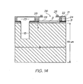
- Figures 12 and 13 show the entire thickness (150 microns) of the silicon wafer 2 after ashing the SAC1 and SAC2 photoresist layers 10 and 16.
- ink supply channels 27 are etched from the backside of the wafer to meet with the ink inlets 15 using a standard anisotropic DRIE. This backside etch is defined using a layer of photoresist (not shown) exposed by the dark tone mask shown in Figure 16 .
- the ink supply channel 27 makes a fluidic connection between the backside of the wafer and the ink inlets 15.
- Figure 1 shows three adjacent rows of nozzles in a cutaway perspective view of a completed printhead integrated circuit.
- Each row of nozzles has a respective ink supply channel 27 extending along its length and supplying ink to a plurality of ink inlets 15 in each row.
- the ink inlets supply ink to the ink conduit 23 for each row, with each nozzle chamber receiving ink from a common ink conduit for that row.
- this prior art MEMS fabrication process inevitably leaves a hydrophilic ink ejection face by virtue of the nozzle plate 56 being formed of ceramic materials, such as silicon dioxide, silicon nitride, silicon oxynitride, aluminium nitride etc.
- the nozzle plate 56 has a hydrophobic polymer deposited thereon immediately after the nozzle opening etch (i.e. at the stage represented in Figures 10 and 11 ). Since the photoresist scaffold layers must be subsequently removed, the polymeric material should be resistant to the ashing process. Preferably, the polymeric material should be resistant to removal by an O 2 or an H 2 ashing plasma.
- the Applicant has identified a family of polymeric materials which meet the above-mentioned requirements of being hydrophobic whilst at the same time being resistant to O 2 or H 2 ashing. These materials are typically polymerized siloxanes or fluorinated polyolefins.
- PDMS polydimethylsiloxane
- PFPE perfluorinated polyethylene
- Such materials form a passivating surface oxide in an O 2 plasma, and subsequently recover their hydrophobicity relatively quickly.
- a further advantage of these materials is that they have excellent adhesion to ceramics, such as silicon dioxide and silicon nitride.
- a further advantage of these materials is that they are photopatternable, which makes them particularly suitable for use in a MEMS process.
- PDMS is curable with UV light, whereby unexposed regions of PDMS can be removed relatively easily.
- FIG 10 there is shown a nozzle assembly of a partially-fabricated printhead after the rim and nozzle etches described earlier. However, instead of proceeding with SAC1 and SAC2 ashing (as shown in Figures 12 and 13 ), at this stage a thin layer ( ca 1 micron) of hydrophobic polymeric material 100 is spun onto the nozzle plate 56, as shown in Figures 19 and 20 .
- this layer of polymeric material is photopatterned so as to remove the material deposited within the nozzle openings 26.
- Photopatterning may comprise exposure of the polymeric layer 100 to UV light, except for those regions within the nozzle openings 26. Accordingly, as shown in Figures 21 and 22 , the printhead now has a hydrophobic nozzle plate, and subsequent MEMS processing steps can proceed analogously to the steps described in connection with Figures 12 to 18 . Significantly, the hydrophobic polymer 100 is not removed by the O 2 ashing steps used to remove the photoresist scaffold 10 and 16.
- the hydrophobic polymer layer 100 is deposited immediately after the stage represented by Figures 7 and 8 . Accordingly, the hydrophobic polymer is spun onto the nozzle plate after the rim 25 is defined by the rim etch, but before the nozzle opening 26 is defined by the nozzle etch.
- FIG. 23 and 24 there is shown a nozzle assembly after deposition of the hydrophobic polymer 100.
- the polymer 100 is then photopatterned so as to remove the material bounded by the rim 25 in the nozzle opening region, as shown in Figures 25 and 26 .
- the hydrophobic polymeric material 100 can now act as an etch mask for etching the nozzle opening 26.
- the nozzle opening 26 is defined by etching through the roof structure 21, which is typically performed using a gas chemistry comprising O 2 and a fluorinated hydrocarbon (e.g. CF 4 or C 4 F 8 ).
- a gas chemistry comprising O 2 and a fluorinated hydrocarbon (e.g. CF 4 or C 4 F 8 ).
- Hydrophobic polymers such as PDMS and PFPE, are normally etched under the same conditions.
- materials such as silicon nitride etch much more rapidly, the roof 21 can be etched selectively using either PDMS or PFPE as an etch mask.
- a gas ratio of 3:1 (CF 4 :O 2 ) silicon nitride etches at about 240 microns per hour, whereas PDMS etches at about 20 microns per hour.
- etch selectivity using a PDMS mask is achievable when defining the nozzle opening 26.
- the nozzle assembly 24 is as shown in Figures 21 and 22 . Accordingly, subsequent MEMS processing steps can proceed analogously to the steps described in connection with Figures 12 to 18 . Significantly, the hydrophobic polymer 100 is not removed by the O 2 ashing steps used to remove the photoresist scaffold 10 and 16.
- Figures 25 and 26 illustrate how the hydrophobic polymer 100 may be used as an etch mask for a nozzle opening etch. Typically, different etch rates between the polymer 100 and the roof 21, as discussed above, provides sufficient etch selectivity.
- a layer of photoresist may be deposited over the hydrophobic polymer 100 shown in Figure 24 , which enables conventional downstream MEMS processing. Having photopatterned this top layer of resist, the hydrophobic polymer 100 and the roof 21 may be etched in one step using the same gas chemistry, with the top layer of a photoresist being used as a standard etch mask.
- a gas chemistry of, for example, CF 4 /O 2 first etches through the hydrophobic polymer 100 and then through the roof 21.
- Subsequent O 2 ashing may be used to remove just the top layer of photoresist (to obtain the nozzle assembly shown in Figures 10 and 11 ), or prolonged O 2 ashing may be used to remove both the top layer of photoresist and the sacrificial photoresist layers 10 and 16 (to obtain the nozzle assembly shown in Figures 12 and 13 ).
- a nozzle plate of a printhead may be hydrophobized in an analogous manner.
- the present invention realizes particular advantages in connection with the Applicant's previously described printhead comprising thermal bend actuator nozzle assemblies. Accordingly, a discussion of how the present invention may be used in such printheads now follows.
- a nozzle assembly may comprise a nozzle chamber having a roof portion which moves relative to a floor portion of the chamber.
- the moveable roof portion is typically actuated to move towards the floor portion by means of a bi-layerad thermal bend actuator.
- Such an actuator may be positioned externally of the nozzle chamber or it may define the moving part of the roof structure.
- a moving roof is advantageous, because it lowers the drop ejection energy by only having one face of the moving structure doing work against the viscous ink.
- a problem with such moving roof structures is that it is necessary to seal the ink inside the nozzle chamber during actuation.
- the nozzle chamber relies on a fluidic seal, which forms a seal using the surface tension of the ink.
- seals are imperfect and it would be desirable to form a mechanical seal which avoids relying on surface tension as a means for containing the ink.
- Such a mechanical seal would need to be sufficiently flexible to accommodate the bending motion of the roof.
- the nozzle assembly 400 comprises a nozzle chamber 401 formed on a passivated CMOS layer 402 of a silicon substrate 403.
- the nozzle chamber is defined by a roof 404 and sidewalls 405 extending from the roof to the passivated CMOS layer 402.
- Ink is supplied to the nozzle chamber 401 by means of an ink inlet 406 in fluid communication with an ink supply channel 407 receiving ink from a backside of the silicon substrate.
- Ink is ejected from the nozzle chamber 401 by means of a nozzle opening 408 defined in the roof 404.
- the nozzle opening 408 is offset from the ink inlet 406.
- the roof 404 has a moving portion 409, which defines a substantial part of the total area of the roof.
- the moving portion 409 defines at least 50% of the total area of the roof 404.
- the nozzle opening 408 and nozzle rim 415 are defined in the moving portion 409, such that the nozzle opening and nozzle rim move with the moving portion.
- the nozzle assembly 400 is characterized in that the moving portion 409 is defined by a thermal bend actuator 410 having a planar upper active beam 411 and a planar lower passive beam 412.
- the actuator 410 typically defines at least 50% of the total area of the roof 404.
- the upper active beam 411 typically defines at least 50% of the total area of the roof 404.
- At least part of the upper active beam 411 is spaced apart from the lower passive beam 412 for maximizing thermal insulation of the two beams. More specifically, a layer of Ti is used as a bridging layer 413 between the upper active beam 411 comprised of TiN and the lower passive beam 412 comprised of SiO 2 .
- the bridging layer 413 allows a gap 414 to be defined in the actuator 410 between the active and passive beams. This gap 414 improves the overall efficiency of the actuator 410 by minimizing thermal transfer from the active beam 411 to the passive beam 412.
- the active beam 411 may, alternatively, be fused or bonded directly to the passive beam 412 for improved structural rigidity.
- Such design modifications would be well within the ambit of the skilled person.
- the active beam 411 is connected to a pair of contacts 416 (positive and ground) via the Ti bridging layer.
- the contacts 416 connect with drive circuitry in the CMOS layers.
- a current flows through the active beam 411 between the two contacts 416.
- the active beam 411 is rapidly heated by the current and expands relative to the passive beam 412, thereby causing the actuator 410 (which defines the moving portion 409 of the roof 404) to bend downwards towards the substrate 403. Since the gap 460 between the moving portion 409 and a static portion 461 is so small, surface tension can generally be relied up to seal this gap when the moving portion is actuated to move towards the substrate 403.
- the movement of the actuator 410 causes ejection of ink from the nozzle opening 408 by a rapid increase of pressure inside the nozzle chamber 401.
- the moving portion 409 of the roof 404 is allowed to return to its quiescent position, which sucks ink from the inlet 406 into the nozzle chamber 401, in readiness for the next ejection.
- a printhead integrated circuit comprises a silicon substrate, an array of nozzle assemblies (typically arranged in rows) formed on the substrate, and drive circuitry for the nozzle assemblies.
- a plurality of printhead integrated circuits may be abutted or linked to form a pagewidth inkjet printhead, as described in, for example, Applicant's earlier US Published Application Nos. 2006/0098044 filed on May 27, 2004 and 2005/0156985 filed on December 20, 2004 .
- An alternative nozzle assembly 500 shown in Figures 31 to 33 is similar to the nozzle assembly 400 insofar as a thermal bend actuator 510, having an upper active beam 511 and a lower passive beam 512, defines a moving portion of a roof 504 of the nozzle chamber 501.
- the nozzle opening 508 and rim 515 are not defined by the moving portion of the roof 504. Rather, the nozzle opening 508 and rim 515 are defined in a fixed or static portion 561 of the roof 504 such that the actuator 510 moves independently of the nozzle opening and rim during droplet ejection.
- An advantage of this arrangement is that it provides more facile control of drop flight direction. Again, the small dimensions of the gap 460, between the moving portion 509 and the static portion 561, is relied up to create a fluidic seal during actuation by using the surface tension of the ink.
- the nozzle assemblies 400 and 500, and corresponding printheads may be constructed using suitable MEMS processes in an analogous manner to those described above.
- the roof of the nozzle chamber (moving or otherwise) is formed by deposition of a roof material onto a suitable sacrificial photoresist scaffold.
- the nozzle assembly 400 previously shown in Figure 27 now has an additional layer of hydrophobic polymer 101 (as described in detail above) coated on the roof, including both the moving 409 and static portions 461 of the roof.
- the hydrophobic polymer 101 seals the gap 460 shown in Figure 27 . It is an advantage of polymers such as PDMS and PFPE that they have extremely low stiffness. Typically, these materials have a Young's modulus of less than 1000 MPa and typically of the order of about 500 MPa.
- Figure 35 shows the nozzle assembly 500 with a hydrophobic polymer coating 101.
- a mechanical seal 562 is formed which provides excellent mechanical sealing of ink in the nozzle chamber 501.
- backside MEMS processing the backside of the wafer is ground to provide a desired wafer thickness (typically 100 to 300 microns) and ink supply channels are etched from a backside of the wafer so as to form a fluidic connection between the backside, which receives ink, and the nozzle assemblies.
- backside MEMS processing may define dicing streets in the wafer so that the wafer can be separated into individual printhead integrated circuits.
- backside MEMS processing is performed after completion of all frontside MEMS fabrication steps, in which nozzle assemblies are constructed on the frontside of the wafer.
- FIGS 36 to 45 outline typical backside MEMS processing steps, as described in US Patent No. 6,846,692 .
- a silicon wafer 212 is provided having a frontside 216 on which is formed a plurality of MEMS nozzle assemblies 218 in a MEMS layer 214.
- the MEMS nozzle assemblies 218 are typically of the form shown in Figures 10 and 11 , in which the nozzle assembly is fully formed with the exception of sacrificial material 10 and 16 filling nozzle chambers.
- a protective layer 220 is interposed between the nozzle assemblies 218.
- This protective layer 220 is typically a relatively thick layer (e.g. 1 to 10 microns) of sacrificial material, such as photoresist, which is spun onto the frontside 216 after fabrication of the MEMS nozzle assemblies 218.
- the photoresist is UV cured and/or hardbaked to provide a rigid and durable protective coating that is suitable for attachment to a glass handle wafer.
- a first holding means in the form of an adhesive tape 222, is bonded to the MEMS layer 14 as illustrated in Figure 37 .
- the tape 222 is bonded to the layer 214 by means of a curable adhesive.
- the adhesive is curable in the sense that it loses its adhesive properties or "tackiness" when exposed to ultraviolet (UV) light or heat.
- the tape 222 described in the specific embodiment described herein is a UV-release tape, although it will be appreciated that thermal-release tapes may be equally suitable for use as the first holding means.
- a handling means in the form of a glass, quartz, alumina or other transparent handle wafer 224 is secured to the tape 222.
- a first operation is performed on the backside 228 of the silicon wafer 212 by backgrinding a surface 228.1 to thin the wafer 12, as illustrated in Figure 39 . This reduces subsequent etch times for etching dicing streets and ink supply channels in the wafer 12.
- each chip 230 has only one MEMS nozzle assembly 218 associated, although it will be appreciated that each chip 230 typically contains an array (e.g. greater than 2000) nozzle assemblies arranged in rows.
- ink supply channels may also be etched so as to provide a fluidic connection to each nozzle assembly 218.
- a second holding means in the form of a second tape 232 is applied to the backside surface 228.1 of the wafer 212.
- a second transparent handle wafer 234 is applied to the tape 232, depending on the equipment being used.
- the tape 232 is bonded to the surface 228.1 of the wafer 212 by means of an adhesive which is also curable when exposed to UV light or heat.
- the first tape 222 and the glass wafer 224 are removed, as illustrated schematically by arrow 236 in Figure 7 .
- the tape 222 is removed by exposing it to UV light which is projected on to the tape 222 through the glass layer 224 as illustrated by arrows 238.
- the glass wafer 224 is transparent to the UV light.
- the silicon wafer 212 is opaque to the UV light so that the tape 232 on the other side of the wafer 212 is not affected by the UV light when the tape 222 is exposed to the UV light.
- a new laminate 240 comprising the silicon wafer with MEMS layer 214, the tape 232 and the glass wafer 234 is turned over to expose the protective layer 220.
- the protective layer 220 is then removed by ashing in an oxygen plasma. This releases the MEMS nozzle assemblies 218, and completes the separation of the chips 242. At the same time as removing the protective layer 220, any other exposed sacrificial material, which remained from frontside MEMS fabrication, is also removed. For example, the sacrificial material 10 and 16 shown in Figures 10 and 11 may be removed at this stage.
- the laminate 240 is placed on an xy wafer stage (not shown) which is reciprocated, as illustrated by arrow 244 in Figure 45 .
- Each MEMS chip 242 when it is desired to remove it, is exposed to UV light as indicated by arrows 246 through a mask 250. This cures the adhesive of the tape 232 locally beneath one particular MEMS chip 242 at a time, to enable that MEMS chip 242 to be removed from the tape 232 by means of a transporting means which may include a vacuum pickup 248.
- the MEMS chips 242 can then be packaged and/or formed into a printhead by butting a plurality of chips together.
- This protective layer 220 must be subsequently removed by an oxidative plasma (ashing). Due to the thickness and constitution of this hardbaked protective layer, ashing times are relatively long.
- the polymer 100 described above may take the place of the sacrificial material used as the protective layer 220.
- the protective layer 220 throughout Figures 36 to 43 may be formed of the polymer 100.
- the polymer 100 instead of being removed before chip separation, as shown in Figure 44 , the polymer 100 remains on the ink ejection face of each chip.
- Frontside dicing streets 251 are defined in the polymer 100 prior to any backside processing (typically by photopatterning at the same time as defining nozzle openings through the polymer 100 - see Figure 21 or Figure 25 ).
- FIG. 46 shows an assembly in which individual MEMS chips 242, having a protective layer 220 comprised of the polymer 100, are ready for removal from the second handle wafer 234.
- Figure 47 is analogous to the stage shown at Figure 43 .
- the use of the second handle wafer 234 may be avoided altogether.
- the individual MEMS chips 242 may be removed directly from the assembly shown in Figure 47 , which is analogous to the stage shown at Figure 40 .
- the chips 230 are releasably attached to the first handle wafer 224 and all backside MEMS processing steps have been completed.
- the polymer 100 may perform the multiple functions of providing a hydrophobic ink ejection face; providing a mechanical seal for thermal bend-actuated nozzles; and providing a protective coating onto which the handle wafer 224 may be attached, using the adhesive tape 222.
- the polymer 100 may be used to facilitate backside MEMS processing steps, as described above.
- hydrophobic polymer described above advantageously streamlines backside MEMS processing by way of reducing the number of steps and shortening ashing times. Furthermore, the use of the polymer 100 enables greater flexibility as to when ashing is performed in the overall process flow. Since the polymer 100 is not sacrificial, the process flow is not dictated by removal of the layer 220 in a late-stage frontside ashing step. When using the polymer 100, backside ashing of sacrificial material 10 and 16 is equally feasible.
Claims (15)
- Ein Verfahren zum Herstellen einer Vielzahl von integrierten MEMS-Schaltkreisen (242) aus einem Wafer mit einer MEMS-Schicht (214), die auf einer Vorderseite davon ausgebildet ist, und einer Polymerbeschichtung auf der MEMS-Schicht (214), wobei die Polymerbeschichtung eine Vielzahl von darin definierten Vorderseiten-Schnittführungen (251) aufweist, wobei das Verfahren die folgenden Schritte umfasst:(a) lösbares Befestigen eines ersten Haltemittels (222) an der Polymerbeschichtung; und(b) Durchführen mindestens eines Arbeitsablaufs an einer Rückseite des Wafers, wobei der mindestens eine Arbeitsablauf das Ätzen einer Vielzahl von Rückseiten-Schnittführungen (250) durch den Wafer einschließt, wobei jede Rückseiten-Schnittführung (250) auf eine jeweilige Vorderseiten-Schnittführung (251) trifft, wodurch dafür gesorgt wird, dass die Vielzahl von integrierten MEMS-Schaltkreisen (242) an dem ersten Haltemittel (222) lösbar befestigt wird, wobei jeder integrierte MEMS-Schaltkreis (242) eine jeweilige Polymerbeschichtung umfasst.
- Das Verfahren nach Anspruch 1, wobei die Polymerbeschichtung gegenüber Ablösung durch ein oxidatives Plasma widerstandsfähig ist.
- Das Verfahren nach Anspruch 2, das den Schritt des Unterwerfens des Wafers einem oxidativen Plasma zum Ablösen von Opfermaterial in der MEMS-Schicht (214) einschließt.
- Das Verfahren nach Anspruch 1, wobei die Polymerbeschichtung ein Polymer umfasst, das aus der Gruppe ausgewählt ist, die folgendes umfasst:polymerisierte Siloxane und fluorierte Polyolefine.
- Das Verfahren nach Anspruch 4, wobei das Polymer aus der Gruppe ausgewählt ist, die folgendes umfasst: Polydimethylsiloxan (PDMS) und perfluoriertes Polyethylen (PFPE).
- Das Verfahren nach Anspruch 1, wobei die MEMS-Schicht (214) eine Vielzahl von Tintenstrahldüsen-Anordnungen (218) umfasst und das Verfahren eine Vielzahl von integrierten Druckkopf-Schaltkreisen bereitstellt.
- Das Verfahren nach Anspruch 6, wobei Schritt (b) das Durchführen mindestens eines Arbeitsablaufs umfasst, der aus der Gruppe ausgewählt ist, die folgendes umfasst:Ausdünnung der Wafer-Rückseite;Ätzen von Tintenzufuhrkanälen an der Rückseite, um eine Fluidverbindung zwischen der Rückseite und den Tintenstrahldüsen-Anordnungen (218) bereitzustellen; undUnterwerfen der Rückseite einem oxidativen Plasma.
- Das Verfahren nach Anspruch 1, wobei das erste Haltemittel mittels eines Klebebandes (222) lösbar befestigt ist.
- Das Verfahren nach Anspruch 8, wobei das Klebeband (222) ein UVlösbares Band oder ein thermisch lösbares Band ist.
- Das Verfahren nach Anspruch 1, wobei das erste Haltemittel ein Handle-Wafer (224) ist.
- Das Verfahren nach Anspruch 1, das ferner den Schritt des Entfernens der integrierten Schaltkreise von dem ersten Haltemittel (222) umfasst.
- Das Verfahren nach Anspruch 1, das die folgenden weiteren Schritte umfasst:(c) lösbares Befestigen eines zweiten Haltemittels (232) an der Rückseite des Wafers; und(d) Entfernen des ersten Haltemittels (222), um die Vielzahl von integrierten MEMS-Schaltkreisen bereitzustellen, die an dem zweiten Haltemittel (232) lösbar befestigt sind.
- Das Verfahren nach Anspruch 12, wobei die Vorderseite dem oxidativen Plasma nach Schritt (d) unterworfen wird.
- Das Verfahren nach Anspruch 13, wobei das zweite Haltemittel (232) aus der Gruppe ausgewählt ist, die folgendes umfasst: einen Handle-Wafer und einen Wafer-Film-Frame.
- Das Verfahren nach Anspruch 1, das ferner die folgenden Anfangsschritte umfasst:(i) Aufbringen einer Polymerbeschichtung auf die MEMS-Schicht (214); und(ii) Definieren einer Vielzahl von Vorderseiten-Schnittführungen (251) durch die Polymerbeschichtung;wobei die Anfangsschritte (i) und (ii) vor den Schritten (a) und (b) durchgeführt werden.
Applications Claiming Priority (2)
| Application Number | Priority Date | Filing Date | Title |
|---|---|---|---|
| US11/763,444 US7605009B2 (en) | 2007-03-12 | 2007-06-15 | Method of fabrication MEMS integrated circuits |
| PCT/AU2008/000553 WO2008151354A1 (en) | 2007-06-15 | 2008-04-22 | Method of fabrication mems integrated circuits |
Publications (3)
| Publication Number | Publication Date |
|---|---|
| EP2158603A1 EP2158603A1 (de) | 2010-03-03 |
| EP2158603A4 EP2158603A4 (de) | 2010-12-01 |
| EP2158603B1 true EP2158603B1 (de) | 2011-09-07 |
Family
ID=40130784
Family Applications (1)
| Application Number | Title | Priority Date | Filing Date |
|---|---|---|---|
| EP08733380A Not-in-force EP2158603B1 (de) | 2007-06-15 | 2008-04-22 | Verfahren zur herstellung von integrierten mems-schaltungen |
Country Status (4)
| Country | Link |
|---|---|
| US (3) | US7605009B2 (de) |
| EP (1) | EP2158603B1 (de) |
| AT (1) | ATE523895T1 (de) |
| WO (1) | WO2008151354A1 (de) |
Families Citing this family (9)
| Publication number | Priority date | Publication date | Assignee | Title |
|---|---|---|---|---|
| US8029097B2 (en) * | 2008-11-26 | 2011-10-04 | Silverbrook Research Pty Ltd | Inkjet nozzle assembly having moving roof structure and sealing bridge |
| US8342650B2 (en) * | 2009-07-24 | 2013-01-01 | Zamtec Ltd | Printhead having polysilsesquioxane coating on ink ejection face |
| US20110018937A1 (en) * | 2009-07-24 | 2011-01-27 | Silverbrook Research Pty Ltd | Printhead having ink ejection face complementing ink or other features of printhead |
| CN102470675B (zh) * | 2009-07-24 | 2014-11-12 | 扎姆泰科有限公司 | 具有在喷墨面上的聚倍半硅氧烷涂层的打印头 |
| US8425004B2 (en) * | 2009-07-24 | 2013-04-23 | Zamtec Ltd | Printhead having polymer incorporating nanoparticles coated on ink ejection face |
| US8883614B1 (en) * | 2013-05-22 | 2014-11-11 | Applied Materials, Inc. | Wafer dicing with wide kerf by laser scribing and plasma etching hybrid approach |
| US9335367B2 (en) | 2013-08-27 | 2016-05-10 | International Business Machines Corporation | Implementing low temperature wafer test |
| US10556317B2 (en) | 2016-03-03 | 2020-02-11 | P.R. Hoffman Machine Products Inc. | Polishing machine wafer holder |
| TW202114873A (zh) * | 2019-06-03 | 2021-04-16 | 愛爾蘭商滿捷特科技公司 | 處理mems晶圓的方法 |
Family Cites Families (43)
| Publication number | Priority date | Publication date | Assignee | Title |
|---|---|---|---|---|
| US2003A (en) * | 1841-03-12 | Improvement in horizontal windivhlls | ||
| US2004A (en) * | 1841-03-12 | Improvement in the manner of constructing and propelling steam-vessels | ||
| US5136310A (en) | 1990-09-28 | 1992-08-04 | Xerox Corporation | Thermal ink jet nozzle treatment |
| US6019457A (en) | 1991-01-30 | 2000-02-01 | Canon Information Systems Research Australia Pty Ltd. | Ink jet print device and print head or print apparatus using the same |
| JP3143308B2 (ja) | 1994-01-31 | 2001-03-07 | キヤノン株式会社 | インクジェット記録ヘッドの製造方法 |
| DE4407839A1 (de) | 1994-03-09 | 1995-09-14 | Eastman Kodak Co | Verfahren zur Beeinflußung des Benetzungswinkels der Düsenaustrittsfläche von Tintendruckköpfen |
| JPH09507804A (ja) | 1994-11-14 | 1997-08-12 | フィリップス エレクトロニクス ネムローゼ フェンノートシャップ | インクジェット記録装置及びインクジェット記録ヘッド |
| US5812158A (en) * | 1996-01-18 | 1998-09-22 | Lexmark International, Inc. | Coated nozzle plate for ink jet printing |
| US5706041A (en) * | 1996-03-04 | 1998-01-06 | Xerox Corporation | Thermal ink-jet printhead with a suspended heating element in each ejector |
| EP0882593A1 (de) | 1997-06-05 | 1998-12-09 | Xerox Corporation | Verfahren zur Herstellung einer hydrophoben/hydrophilen Stirnseite eines Farbstrahldruckkopfes |
| US6260953B1 (en) | 1997-07-15 | 2001-07-17 | Silverbrook Research Pty Ltd | Surface bend actuator vented ink supply ink jet printing mechanism |
| US6062679A (en) | 1997-08-28 | 2000-05-16 | Hewlett-Packard Company | Printhead for an inkjet cartridge and method for producing the same |
| FR2768817B1 (fr) * | 1997-09-19 | 1999-12-10 | Cis Bio Int | Methode homogene pour la detection et/ou la determination de l'activite phosphorylante d'un materiel biologique |
| US6260114B1 (en) * | 1997-12-30 | 2001-07-10 | Mcmz Technology Innovations, Llc | Computer cache memory windowing |
| US6151045A (en) | 1999-01-22 | 2000-11-21 | Lexmark International, Inc. | Surface modified nozzle plate |
| US6345880B1 (en) * | 1999-06-04 | 2002-02-12 | Eastman Kodak Company | Non-wetting protective layer for ink jet print heads |
| US6302523B1 (en) | 1999-07-19 | 2001-10-16 | Xerox Corporation | Ink jet printheads |
| US6425971B1 (en) * | 2000-05-10 | 2002-07-30 | Silverbrook Research Pty Ltd | Method of fabricating devices incorporating microelectromechanical systems using UV curable tapes |
| DE60035618T2 (de) * | 2000-05-24 | 2008-07-03 | Silverbrook Research Pty. Ltd., Balmain | Herstellungsverfahren für einen tintenstrahldruckkopf mit bewegender düse und externem betätiger |
| JP3616872B2 (ja) * | 2000-09-14 | 2005-02-02 | 住友電気工業株式会社 | ダイヤモンドウエハのチップ化方法 |
| US6759273B2 (en) * | 2000-12-05 | 2004-07-06 | Analog Devices, Inc. | Method and device for protecting micro electromechanical systems structures during dicing of a wafer |
| US6409312B1 (en) | 2001-03-27 | 2002-06-25 | Lexmark International, Inc. | Ink jet printer nozzle plate and process therefor |
| WO2003015890A1 (en) | 2001-08-20 | 2003-02-27 | President And Fellows Of Harvard College | Fluidic arrays and method of using |
| US6573156B1 (en) * | 2001-12-13 | 2003-06-03 | Omm, Inc. | Low defect method for die singulation and for structural support for handling thin film devices |
| JP2004004299A (ja) | 2002-05-31 | 2004-01-08 | Renesas Technology Corp | 電子装置の製造方法 |
| US7052117B2 (en) * | 2002-07-03 | 2006-05-30 | Dimatix, Inc. | Printhead having a thin pre-fired piezoelectric layer |
| KR100468859B1 (ko) | 2002-12-05 | 2005-01-29 | 삼성전자주식회사 | 일체형 잉크젯 프린트헤드 및 그 제조방법 |
| ITTO20021099A1 (it) | 2002-12-19 | 2004-06-20 | Olivetti I Jet Spa | Processo di rivestimento protettivo di microcircuiti idraulici rispetto a liquidi aggressivi. particolarmente per una testina di stampa a getto d'inchiostro. |
| KR100474851B1 (ko) | 2003-01-15 | 2005-03-09 | 삼성전자주식회사 | 잉크 토출 방법 및 이를 채용한 잉크젯 프린트헤드 |
| US7758158B2 (en) | 2003-07-22 | 2010-07-20 | Canon Kabushiki Kaisha | Ink jet head and its manufacture method |
| JP2005150235A (ja) * | 2003-11-12 | 2005-06-09 | Three M Innovative Properties Co | 半導体表面保護シート及び方法 |
| US7448734B2 (en) | 2004-01-21 | 2008-11-11 | Silverbrook Research Pty Ltd | Inkjet printer cartridge with pagewidth printhead |
| US7163640B2 (en) * | 2004-05-21 | 2007-01-16 | Hewlett-Packard Development Company, L.P. | Methods and systems for laser processing |
| JP2005342808A (ja) * | 2004-05-31 | 2005-12-15 | Oki Electric Ind Co Ltd | Memsデバイスの製造方法 |
| WO2006105581A1 (en) * | 2005-04-04 | 2006-10-12 | Silverbrook Research Pty Ltd | Printhead assembly suitable for redirecting ejected ink droplets |
| US7328976B2 (en) * | 2005-04-04 | 2008-02-12 | Silverbrook Research Pty Ltd. | Hydrophobically coated printhead |
| US7600856B2 (en) | 2006-12-12 | 2009-10-13 | Eastman Kodak Company | Liquid ejector having improved chamber walls |
| FR2912148B1 (fr) | 2007-02-07 | 2009-04-10 | Arkema France | Materiau polymere de type styrene / anhydride, greffe ayant des proprietes ameliorees |
| US7794613B2 (en) | 2007-03-12 | 2010-09-14 | Silverbrook Research Pty Ltd | Method of fabricating printhead having hydrophobic ink ejection face |
| US7938974B2 (en) * | 2007-03-12 | 2011-05-10 | Silverbrook Research Pty Ltd | Method of fabricating printhead using metal film for protecting hydrophobic ink ejection face |
| US7669967B2 (en) * | 2007-03-12 | 2010-03-02 | Silverbrook Research Pty Ltd | Printhead having hydrophobic polymer coated on ink ejection face |
| US7976132B2 (en) * | 2007-03-12 | 2011-07-12 | Silverbrook Research Pty Ltd | Printhead having moving roof structure and mechanical seal |
| KR101318443B1 (ko) | 2009-05-29 | 2013-10-16 | 엘지디스플레이 주식회사 | 입체영상 표시장치 |
-
2007
- 2007-06-15 US US11/763,444 patent/US7605009B2/en active Active
-
2008
- 2008-04-22 AT AT08733380T patent/ATE523895T1/de not_active IP Right Cessation
- 2008-04-22 EP EP08733380A patent/EP2158603B1/de not_active Not-in-force
- 2008-04-22 WO PCT/AU2008/000553 patent/WO2008151354A1/en active Application Filing
-
2009
- 2009-09-21 US US12/563,956 patent/US7986039B2/en not_active Expired - Fee Related
-
2011
- 2011-05-30 US US13/118,457 patent/US8672454B2/en active Active
Also Published As
| Publication number | Publication date |
|---|---|
| US8672454B2 (en) | 2014-03-18 |
| EP2158603A1 (de) | 2010-03-03 |
| US7986039B2 (en) | 2011-07-26 |
| US20100090296A1 (en) | 2010-04-15 |
| US7605009B2 (en) | 2009-10-20 |
| WO2008151354A1 (en) | 2008-12-18 |
| US20110228007A1 (en) | 2011-09-22 |
| EP2158603A4 (de) | 2010-12-01 |
| US20080227229A1 (en) | 2008-09-18 |
| ATE523895T1 (de) | 2011-09-15 |
Similar Documents
| Publication | Publication Date | Title |
|---|---|---|
| US7568787B2 (en) | Printhead including seal membrane | |
| US7669967B2 (en) | Printhead having hydrophobic polymer coated on ink ejection face | |
| US8672454B2 (en) | Ink printhead having ceramic nozzle plate defining movable portions | |
| US7938974B2 (en) | Method of fabricating printhead using metal film for protecting hydrophobic ink ejection face | |
| US7976132B2 (en) | Printhead having moving roof structure and mechanical seal | |
| CA2675856C (en) | Method of fabricating printhead having hydrophobic ink ejection face | |
| US8491803B2 (en) | Method of hydrophobizing and patterning frontside surface of integrated circuit | |
| US8500247B2 (en) | Nozzle assembly having polymeric coating on moving and stationary portions of roof | |
| US7862734B2 (en) | Method of fabricating nozzle assembly having moving roof structure and sealing bridge | |
| EP2349724B1 (de) | Tintenstrahldüsenanordnung mit sich bewegender dachstruktur und dichtungsbrücke | |
| US7901054B2 (en) | Printhead including moving portions and sealing bridges |
Legal Events
| Date | Code | Title | Description |
|---|---|---|---|
| PUAI | Public reference made under article 153(3) epc to a published international application that has entered the european phase |
Free format text: ORIGINAL CODE: 0009012 |
|
| 17P | Request for examination filed |
Effective date: 20091019 |
|
| AK | Designated contracting states |
Kind code of ref document: A1 Designated state(s): AT BE BG CH CY CZ DE DK EE ES FI FR GB GR HR HU IE IS IT LI LT LU LV MC MT NL NO PL PT RO SE SI SK TR |
|
| AX | Request for extension of the european patent |
Extension state: AL BA MK RS |
|
| DAX | Request for extension of the european patent (deleted) | ||
| A4 | Supplementary search report drawn up and despatched |
Effective date: 20101028 |
|
| RIC1 | Information provided on ipc code assigned before grant |
Ipc: B41J 2/16 20060101ALI20101022BHEP Ipc: H01L 21/78 20060101AFI20090105BHEP |
|
| 17Q | First examination report despatched |
Effective date: 20101111 |
|
| GRAP | Despatch of communication of intention to grant a patent |
Free format text: ORIGINAL CODE: EPIDOSNIGR1 |
|
| RIC1 | Information provided on ipc code assigned before grant |
Ipc: B41J 2/16 20060101ALI20110330BHEP Ipc: H01L 21/78 20060101AFI20110330BHEP |
|
| GRAS | Grant fee paid |
Free format text: ORIGINAL CODE: EPIDOSNIGR3 |
|
| GRAA | (expected) grant |
Free format text: ORIGINAL CODE: 0009210 |
|
| REG | Reference to a national code |
Ref country code: GB Ref legal event code: FG4D |
|
| REG | Reference to a national code |
Ref country code: CH Ref legal event code: EP |
|
| REG | Reference to a national code |
Ref country code: IE Ref legal event code: FG4D |
|
| REG | Reference to a national code |
Ref country code: DE Ref legal event code: R096 Ref document number: 602008009573 Country of ref document: DE Effective date: 20111110 |
|
| REG | Reference to a national code |
Ref country code: NL Ref legal event code: VDEP Effective date: 20110907 |
|
| PG25 | Lapsed in a contracting state [announced via postgrant information from national office to epo] |
Ref country code: SE Free format text: LAPSE BECAUSE OF FAILURE TO SUBMIT A TRANSLATION OF THE DESCRIPTION OR TO PAY THE FEE WITHIN THE PRESCRIBED TIME-LIMIT Effective date: 20110907 Ref country code: LT Free format text: LAPSE BECAUSE OF FAILURE TO SUBMIT A TRANSLATION OF THE DESCRIPTION OR TO PAY THE FEE WITHIN THE PRESCRIBED TIME-LIMIT Effective date: 20110907 Ref country code: NO Free format text: LAPSE BECAUSE OF FAILURE TO SUBMIT A TRANSLATION OF THE DESCRIPTION OR TO PAY THE FEE WITHIN THE PRESCRIBED TIME-LIMIT Effective date: 20111207 Ref country code: HR Free format text: LAPSE BECAUSE OF FAILURE TO SUBMIT A TRANSLATION OF THE DESCRIPTION OR TO PAY THE FEE WITHIN THE PRESCRIBED TIME-LIMIT Effective date: 20110907 Ref country code: FI Free format text: LAPSE BECAUSE OF FAILURE TO SUBMIT A TRANSLATION OF THE DESCRIPTION OR TO PAY THE FEE WITHIN THE PRESCRIBED TIME-LIMIT Effective date: 20110907 |
|
| LTIE | Lt: invalidation of european patent or patent extension |
Effective date: 20110907 |
|
| PG25 | Lapsed in a contracting state [announced via postgrant information from national office to epo] |
Ref country code: SI Free format text: LAPSE BECAUSE OF FAILURE TO SUBMIT A TRANSLATION OF THE DESCRIPTION OR TO PAY THE FEE WITHIN THE PRESCRIBED TIME-LIMIT Effective date: 20110907 Ref country code: LV Free format text: LAPSE BECAUSE OF FAILURE TO SUBMIT A TRANSLATION OF THE DESCRIPTION OR TO PAY THE FEE WITHIN THE PRESCRIBED TIME-LIMIT Effective date: 20110907 Ref country code: GR Free format text: LAPSE BECAUSE OF FAILURE TO SUBMIT A TRANSLATION OF THE DESCRIPTION OR TO PAY THE FEE WITHIN THE PRESCRIBED TIME-LIMIT Effective date: 20111208 Ref country code: CY Free format text: LAPSE BECAUSE OF FAILURE TO SUBMIT A TRANSLATION OF THE DESCRIPTION OR TO PAY THE FEE WITHIN THE PRESCRIBED TIME-LIMIT Effective date: 20110907 Ref country code: AT Free format text: LAPSE BECAUSE OF FAILURE TO SUBMIT A TRANSLATION OF THE DESCRIPTION OR TO PAY THE FEE WITHIN THE PRESCRIBED TIME-LIMIT Effective date: 20110907 |
|
| REG | Reference to a national code |
Ref country code: AT Ref legal event code: MK05 Ref document number: 523895 Country of ref document: AT Kind code of ref document: T Effective date: 20110907 |
|
| PG25 | Lapsed in a contracting state [announced via postgrant information from national office to epo] |
Ref country code: BE Free format text: LAPSE BECAUSE OF FAILURE TO SUBMIT A TRANSLATION OF THE DESCRIPTION OR TO PAY THE FEE WITHIN THE PRESCRIBED TIME-LIMIT Effective date: 20110907 |
|
| PG25 | Lapsed in a contracting state [announced via postgrant information from national office to epo] |
Ref country code: CZ Free format text: LAPSE BECAUSE OF FAILURE TO SUBMIT A TRANSLATION OF THE DESCRIPTION OR TO PAY THE FEE WITHIN THE PRESCRIBED TIME-LIMIT Effective date: 20110907 Ref country code: SK Free format text: LAPSE BECAUSE OF FAILURE TO SUBMIT A TRANSLATION OF THE DESCRIPTION OR TO PAY THE FEE WITHIN THE PRESCRIBED TIME-LIMIT Effective date: 20110907 Ref country code: IS Free format text: LAPSE BECAUSE OF FAILURE TO SUBMIT A TRANSLATION OF THE DESCRIPTION OR TO PAY THE FEE WITHIN THE PRESCRIBED TIME-LIMIT Effective date: 20120107 |
|
| PG25 | Lapsed in a contracting state [announced via postgrant information from national office to epo] |
Ref country code: RO Free format text: LAPSE BECAUSE OF FAILURE TO SUBMIT A TRANSLATION OF THE DESCRIPTION OR TO PAY THE FEE WITHIN THE PRESCRIBED TIME-LIMIT Effective date: 20110907 Ref country code: PL Free format text: LAPSE BECAUSE OF FAILURE TO SUBMIT A TRANSLATION OF THE DESCRIPTION OR TO PAY THE FEE WITHIN THE PRESCRIBED TIME-LIMIT Effective date: 20110907 Ref country code: EE Free format text: LAPSE BECAUSE OF FAILURE TO SUBMIT A TRANSLATION OF THE DESCRIPTION OR TO PAY THE FEE WITHIN THE PRESCRIBED TIME-LIMIT Effective date: 20110907 Ref country code: IT Free format text: LAPSE BECAUSE OF FAILURE TO SUBMIT A TRANSLATION OF THE DESCRIPTION OR TO PAY THE FEE WITHIN THE PRESCRIBED TIME-LIMIT Effective date: 20110907 Ref country code: NL Free format text: LAPSE BECAUSE OF FAILURE TO SUBMIT A TRANSLATION OF THE DESCRIPTION OR TO PAY THE FEE WITHIN THE PRESCRIBED TIME-LIMIT Effective date: 20110907 Ref country code: PT Free format text: LAPSE BECAUSE OF FAILURE TO SUBMIT A TRANSLATION OF THE DESCRIPTION OR TO PAY THE FEE WITHIN THE PRESCRIBED TIME-LIMIT Effective date: 20120109 |
|
| PLBE | No opposition filed within time limit |
Free format text: ORIGINAL CODE: 0009261 |
|
| STAA | Information on the status of an ep patent application or granted ep patent |
Free format text: STATUS: NO OPPOSITION FILED WITHIN TIME LIMIT |
|
| PG25 | Lapsed in a contracting state [announced via postgrant information from national office to epo] |
Ref country code: DK Free format text: LAPSE BECAUSE OF FAILURE TO SUBMIT A TRANSLATION OF THE DESCRIPTION OR TO PAY THE FEE WITHIN THE PRESCRIBED TIME-LIMIT Effective date: 20110907 |
|
| 26N | No opposition filed |
Effective date: 20120611 |
|
| REG | Reference to a national code |
Ref country code: DE Ref legal event code: R097 Ref document number: 602008009573 Country of ref document: DE Effective date: 20120611 |
|
| PG25 | Lapsed in a contracting state [announced via postgrant information from national office to epo] |
Ref country code: MC Free format text: LAPSE BECAUSE OF NON-PAYMENT OF DUE FEES Effective date: 20120430 |
|
| REG | Reference to a national code |
Ref country code: CH Ref legal event code: PL |
|
| PG25 | Lapsed in a contracting state [announced via postgrant information from national office to epo] |
Ref country code: LI Free format text: LAPSE BECAUSE OF NON-PAYMENT OF DUE FEES Effective date: 20120430 Ref country code: CH Free format text: LAPSE BECAUSE OF NON-PAYMENT OF DUE FEES Effective date: 20120430 |
|
| PG25 | Lapsed in a contracting state [announced via postgrant information from national office to epo] |
Ref country code: ES Free format text: LAPSE BECAUSE OF FAILURE TO SUBMIT A TRANSLATION OF THE DESCRIPTION OR TO PAY THE FEE WITHIN THE PRESCRIBED TIME-LIMIT Effective date: 20111218 |
|
| PG25 | Lapsed in a contracting state [announced via postgrant information from national office to epo] |
Ref country code: BG Free format text: LAPSE BECAUSE OF FAILURE TO SUBMIT A TRANSLATION OF THE DESCRIPTION OR TO PAY THE FEE WITHIN THE PRESCRIBED TIME-LIMIT Effective date: 20111207 |
|
| PG25 | Lapsed in a contracting state [announced via postgrant information from national office to epo] |
Ref country code: MT Free format text: LAPSE BECAUSE OF FAILURE TO SUBMIT A TRANSLATION OF THE DESCRIPTION OR TO PAY THE FEE WITHIN THE PRESCRIBED TIME-LIMIT Effective date: 20110907 |
|
| PG25 | Lapsed in a contracting state [announced via postgrant information from national office to epo] |
Ref country code: TR Free format text: LAPSE BECAUSE OF FAILURE TO SUBMIT A TRANSLATION OF THE DESCRIPTION OR TO PAY THE FEE WITHIN THE PRESCRIBED TIME-LIMIT Effective date: 20110907 |
|
| PG25 | Lapsed in a contracting state [announced via postgrant information from national office to epo] |
Ref country code: LU Free format text: LAPSE BECAUSE OF NON-PAYMENT OF DUE FEES Effective date: 20120422 |
|
| REG | Reference to a national code |
Ref country code: GB Ref legal event code: 732E Free format text: REGISTERED BETWEEN 20140619 AND 20140625 |
|
| PG25 | Lapsed in a contracting state [announced via postgrant information from national office to epo] |
Ref country code: HU Free format text: LAPSE BECAUSE OF FAILURE TO SUBMIT A TRANSLATION OF THE DESCRIPTION OR TO PAY THE FEE WITHIN THE PRESCRIBED TIME-LIMIT Effective date: 20080422 |
|
| REG | Reference to a national code |
Ref country code: DE Ref legal event code: R081 Ref document number: 602008009573 Country of ref document: DE Owner name: MEMJET TECHNOLOGY LIMITED, IE Free format text: FORMER OWNER: SILVERBROOK RESEARCH PTY. LTD., BALMAIN, NEW SOUTH WALES, AU Effective date: 20141016 |
|
| REG | Reference to a national code |
Ref country code: FR Ref legal event code: CD Owner name: MEMJET TECHNOLOGY LIMITED, IE Effective date: 20141118 Ref country code: FR Ref legal event code: CA Effective date: 20141118 Ref country code: FR Ref legal event code: TP Owner name: MEMJET TECHNOLOGY LIMITED, IE Effective date: 20141118 |
|
| REG | Reference to a national code |
Ref country code: FR Ref legal event code: PLFP Year of fee payment: 9 |
|
| REG | Reference to a national code |
Ref country code: FR Ref legal event code: PLFP Year of fee payment: 10 |
|
| PGFP | Annual fee paid to national office [announced via postgrant information from national office to epo] |
Ref country code: CZ Payment date: 20170905 Year of fee payment: 13 Ref country code: IE Payment date: 20170428 Year of fee payment: 10 |
|
| REG | Reference to a national code |
Ref country code: IE Ref legal event code: MM4A |
|
| PG25 | Lapsed in a contracting state [announced via postgrant information from national office to epo] |
Ref country code: IE Free format text: LAPSE BECAUSE OF NON-PAYMENT OF DUE FEES Effective date: 20180422 Ref country code: FR Free format text: LAPSE BECAUSE OF NON-PAYMENT OF DUE FEES Effective date: 20180430 |
|
| PGFP | Annual fee paid to national office [announced via postgrant information from national office to epo] |
Ref country code: GB Payment date: 20220427 Year of fee payment: 15 Ref country code: DE Payment date: 20220427 Year of fee payment: 15 |
|
| REG | Reference to a national code |
Ref country code: DE Ref legal event code: R119 Ref document number: 602008009573 Country of ref document: DE |
|
| GBPC | Gb: european patent ceased through non-payment of renewal fee |
Effective date: 20230422 |
|
| PG25 | Lapsed in a contracting state [announced via postgrant information from national office to epo] |
Ref country code: GB Free format text: LAPSE BECAUSE OF NON-PAYMENT OF DUE FEES Effective date: 20230422 |
|
| PG25 | Lapsed in a contracting state [announced via postgrant information from national office to epo] |
Ref country code: GB Free format text: LAPSE BECAUSE OF NON-PAYMENT OF DUE FEES Effective date: 20230422 Ref country code: DE Free format text: LAPSE BECAUSE OF NON-PAYMENT OF DUE FEES Effective date: 20231103 |