EP2158351B1 - Dispositif de repassage à vapeur avec système anti-goutte - Google Patents
Dispositif de repassage à vapeur avec système anti-goutte Download PDFInfo
- Publication number
- EP2158351B1 EP2158351B1 EP08760413A EP08760413A EP2158351B1 EP 2158351 B1 EP2158351 B1 EP 2158351B1 EP 08760413 A EP08760413 A EP 08760413A EP 08760413 A EP08760413 A EP 08760413A EP 2158351 B1 EP2158351 B1 EP 2158351B1
- Authority
- EP
- European Patent Office
- Prior art keywords
- steam
- ironing
- temperature setting
- micropump
- drip
- Prior art date
- Legal status (The legal status is an assumption and is not a legal conclusion. Google has not performed a legal analysis and makes no representation as to the accuracy of the status listed.)
- Active
Links
Images


Classifications
-
- D—TEXTILES; PAPER
- D06—TREATMENT OF TEXTILES OR THE LIKE; LAUNDERING; FLEXIBLE MATERIALS NOT OTHERWISE PROVIDED FOR
- D06F—LAUNDERING, DRYING, IRONING, PRESSING OR FOLDING TEXTILE ARTICLES
- D06F75/00—Hand irons
- D06F75/08—Hand irons internally heated by electricity
- D06F75/10—Hand irons internally heated by electricity with means for supplying steam to the article being ironed
- D06F75/14—Hand irons internally heated by electricity with means for supplying steam to the article being ironed the steam being produced from water in a reservoir carried by the iron
- D06F75/16—Hand irons internally heated by electricity with means for supplying steam to the article being ironed the steam being produced from water in a reservoir carried by the iron the reservoir being heated to produce the steam
-
- D—TEXTILES; PAPER
- D06—TREATMENT OF TEXTILES OR THE LIKE; LAUNDERING; FLEXIBLE MATERIALS NOT OTHERWISE PROVIDED FOR
- D06F—LAUNDERING, DRYING, IRONING, PRESSING OR FOLDING TEXTILE ARTICLES
- D06F75/00—Hand irons
- D06F75/08—Hand irons internally heated by electricity
- D06F75/26—Temperature control or indicating arrangements
Definitions
- a soleplate with steam outlet openings comprising the following components: a soleplate with steam outlet openings; a container for evaporation liquid, in particular water; a steam generating system having an evaporation chamber communicating with the steam outlets and into which the evaporation liquid from the container is selectively introduced; a heating device for heating the soleplate and / or the evaporation chamber; an ironing temperature adjusting element; an operating element for selectively activating and deactivating the steam generating system; and an anti-dripping system for preventing unwanted entry of the evaporating liquid into the evaporating chamber and thereby preventing accidental leakage of (non-evaporated) evaporating liquid from the steam outlets.
- Anti-dripping systems are usually used to prevent the entry of the evaporation liquid in the evaporation chamber, if this (for example, shortly after switching on in a heating phase of the soleplate or the evaporation chamber or even after switching off the steam ironing device or a ironing operation with an ironing temperature lower than a steam ironing temperature) has a temperature insufficient to vaporize evaporation liquid in the evaporation chamber.
- evaporating liquid drops unintentionally escape from the steam outlet openings of the soleplate and fall on an ironing board or to be ironed or just ironed textiles and adversely affect the textiles or the previously achieved ironing results.
- Conventional anti-drip systems are usually equipped with a bimetallic element which controls the supply or the entry of the evaporation liquid into the evaporation chamber depending on the temperature in the evaporation chamber or the temperature of the soleplate. This control is carried out by means of a temperature-induced deformation of the bimetallic element, which is used to realize a circuit function.
- the bimetallic element is coupled to a valve system which is actuated by the bimetallic element, thus opening or closing an evaporation liquid channel which opens into the vaporization chamber.
- the bimetallic element serves to To operate an electrical switch that closes or interrupts the electrical circuit of the micropump.
- steam ironing apparatus provided with a micropump are also known which do not have an anti-drip system and consequently can not prevent the evaporation of evaporating liquid from the soleplate in certain conditions.
- the invention has the object or the technical problem of providing a steam ironing device with an improved anti-drip system.
- This steam ironing apparatus in particular a steam iron or a steam ironing station, comprises: a soleplate with steam outlet openings; a container for evaporation liquid, in particular water; a steam generating system having an evaporation chamber communicating with the steam outlets and into which the evaporation liquid from the container is selectively introduced; a heating device for heating the soleplate and / or the evaporation chamber; an ironing temperature adjusting element; an operating element for selectively activating and deactivating the steam generating system (e.g., a so-called "steam switch”); and an anti-dripping system for preventing unwanted entry of the evaporating liquid into the evaporating chamber and thereby preventing accidental leakage of (non-evaporated) evaporating liquid from the steam outlets operably coupled to and activatable and deactivatable by the ironing temperature adjusting member.
- a steam generating system having an evaporation chamber communicating with the steam outlets and into which the evaporation liquid from the container is selectively introduced
- the ironing temperature adjusting element according to the invention has a first temperature setting range for low ironing temperatures, in which the anti-drip system can be activated via or through the ironing temperature setting element.
- Disabled via this means in the context of the present invention that the deactivation function can start from a different control element of the steam ironing device than the ironing temperature setting element, but the ironing temperature setting element must additionally assume a predetermined state, so that the anti-drip system is deactivated and evaporation liquid in the Evaporation chamber can get.
- an anti-drip system circuit of an electric anti-drip system for example, at least two predetermined switching conditions or states (of the operating element AND of the ironing temperature setting element) must be fulfilled so that the anti-drip system is deactivated and evaporation liquid can enter the evaporation chamber.
- “Activatable over this" in the context of the present invention further means that even if, in addition to the ironing temperature setting element other operating elements of the steam ironing device are present, the
- the activation function can already be triggered by a predetermined state or switching state of at least one of these elements (or more or all).
- a bimetal element assigned to the anti-drip system is completely dispensed with.
- the anti-drip system is functionally coupled to the ironing temperature setting element and can be activated or deactivated via or through it.
- the influence of the local temperature in the region of the mounting location of the anti-drip system and the associated technical disadvantages can be eliminated.
- the anti-drip system is controlled by or via the ironing temperature setting element, the function of the anti-drip system can be targeted, precisely and without delays to one by means of the ironing temperature setting element Adjust or adjust the preselected concrete ironing temperature.
- the entry of evaporation liquid into the evaporation chamber and the dripping out of non-evaporated evaporation liquid from the soleplate can be reliably prevented.
- it is possible to preclude erroneous operation by a user if, for example, he operates the operating element for activating the steam generating system, although due to a preselected low ironing temperature, the temperature in the evaporating chamber is insufficient to evaporate the introduced evaporating liquid.
- the anti-drip system is appropriately activated by or via the ironing temperature setting element and prevents the introduction of evaporation liquid into the evaporation chamber.
- FIG. 1 is shown in a schematic cross-sectional view of a steam ironing device according to the invention, which is designed in this example as a steam iron 2.
- the steam iron 2 has a first, lower housing part 2a, a soleplate 4 with steam outlet openings 6, a container 8 for evaporation liquid W, in particular water or water with an additive, and a steam generating system, with an evaporation chamber 10, which communicates with the steam outlet openings 6 and in which the evaporation liquid W is selectively introduced from the container 8.
- An electric micropump P1 serves for the controlled introduction of the evaporation liquid W from the container 8 into the evaporation chamber 10.
- a steam quantity (rotary) switch 12 which is functionally coupled to the micropump P1, for a steam iron operation, the desired amount of steam can be adjusted or regulated.
- the steam iron 2 is equipped with a heater 14 for heating the soleplate 4 and / or the evaporation chamber 10.
- a heater 14 for heating the soleplate 4 and / or the evaporation chamber 10.
- the steam iron 2 has an ironing temperature adjusting element, which in this case is designed as a rotary knob 16 which is coupled to a rotation axis 18 which is connected to a thermostat 20 which controls the heating device 14.
- a knob 16 any other suitable for the purpose mentioned adjustment can be used.
- the knob 16 has a plurality of temperature setting ranges, which will be discussed in more detail below.
- the steam iron 2 is equipped with a cleaning and descaling system.
- the steam iron 2 has (at least) a first electrical switch S1 (here: an electrical micro-switch), which is assigned to the knob 16 and can be actuated by this directly or indirectly.
- a first electrical switch S1 here: an electrical micro-switch
- the knob 16 and the ironing temperature setting element may also have two or more switches.
- an operating element 22 is provided for selectively activating and deactivating the steam generating system.
- This operating element 22 is designed in the present case as a so-called steam switch. In principle, however, any other suitable for the purpose mentioned control element can apply.
- the steam iron 2 has (at least) a second electrical switch S2, which is assigned to the steam switch 22 and can be actuated by it directly or indirectly.
- the switch S2 is functionally coupled to the micropump P1.
- the steam iron 2 has a steam button 24, which is coupled to a separate from the micropump P1, mechanical pump P2.
- a "key” is to be understood, in addition to a key as such, also a switch, knob, etc.
- the steam iron 2 is further equipped with an anti-dripping system for preventing unwanted entry of the evaporating liquid W into the evaporating chamber 10 and thus preventing accidental leakage of (non-evaporated) evaporating liquid W from the steam outlets 6. Furthermore, the steam iron 2 has a central anti-drip control system Z.
- the anti-drip system is at least functionally coupled to the rotary knob 16 (ironing temperature setting element) and can be activated or deactivated via or through it.
- the knob 16 is coupled to the anti-drip control system Z.
- the anti-drip system may thus be activated and deactivated via or through the first electrical switch S1 associated with the rotary knob 16, as will be described in more detail below.
- the steam switch 22 and the steam quantity rotary switch 12 are coupled to the anti-drip control system Z.
- the knob 16 and the steam switch 22 are on the anti-drip control system Z and the circuit of their switches S1 and S2 (see Fig. 3 ) functionally coupled with each other.
- the micropump P1 forms the anti-drip system or a substantial part thereof.
- the knob 16 and the steam switch 22 in this case constitute essential components of an anti-drip system circuit or a micropump circuit system.
- the separate mechanical pump P2 may have its own anti-drip system.
- FIG. 2 is a schematic perspective view of the first, lower housing part 2a of the steam iron 2 according to the invention shown.
- this housing part 2a has a region 26 for mounting the rotary knob 16 (see Fig. 1 ), with an opening 28 for the axis of rotation 18 (see Fig. 1 ), a stop 30 for the knob 16 and a receptacle 32 for the switch S1.
- Fig. 3 is a bottom perspective view of the knob 16 is shown.
- the knob has a member 34 for establishing a rotationally fixed connection to the axis of rotation 18 of the thermostat 20 (see Fig. 1 ), a stop 30 (see Fig. 2 ) associated stop member 36, a circular segment-shaped large switching element SE1 and a circular segment-shaped small switching element SE2.
- Fig. 4 shows a partially sectioned perspective view of a substantial portion of the steam iron 2 according to the invention, with the arrangement of the knob 16 and located in the receptacle 32 switch S1 on the first, lower housing part 2a. Furthermore, this figure shows the arrangement of the first, lower housing part 2a in relation to a second or further lower housing part 2b.
- the switch S1 has a contact element 38 for opening and closing a circuit to which the switch S1 is connected.
- the contact element 38 in an unactuated normal position, ie the circuit is open.
- the contact element 38 (and Thus, the switch S1) can be actuated by the switching elements SE1 and SE2 when the knob 16 is rotated and the switching element SE1 and SE2 depresses the contact element 38, as will be explained in more detail below.
- Fig. 5 shows a schematic block diagram of an essential part of the anti-drip system and its anti-drip system or the corresponding micropump circuit system of the steam iron 2 according to the invention.
- the reference symbol U denotes the voltage applied to this circuit electrical voltage.
- the second electrical switch S2 is functionally coupled to the first electrical switch S1. More specifically, in the present embodiment, the first switch S1 and the second switch S2 are connected in series.
- the electric micropump P1 which constitutes the anti-drip system or a substantial part thereof, can be activated and deactivated via or via the first switch S1 and the second switch S2, as will be described in more detail below. Since the switch S1 the rotary knob 16 and the switch S2 is assigned to the steam switch 22, and the switches S1, S2 are actuated by these elements, the knob 16 and the steam switch 22 are thus functionally coupled together.
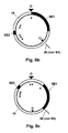
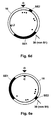
- Fig. 6a to 6e each show a schematic plan view of the knob 16 (iron temperature adjustment) of the steam iron 2 according to the invention in different rotational positions and circuit states.
- the rotation of the knob 16 is in the Fig. 6a indicated by a double arrow.
- the position of the contact element 38 of the switch S1 in relation to the rotary knob 16 and its large switching element SE1 and its small switching element SE2 in dependence on the rotational position of the knob 16 is apparent.
- This position of the contact element 38 of the located below the knob 16 switch S1 is in the illustration according to Fig. 6a indicated by a drawn in the vicinity of the outer periphery of the knob 16 line.
- the knob 16 has several temperature setting ranges. In the drawing, these areas and corresponding adjustment marks with respect to a reference position (eg, a zero position) of the rotary knob 16 are shown.
- the reference position is in the Fig. 6a to 6e indicated by a large arrowhead and the reference numeral 0.
- the rotary knob 16 has a first temperature setting range TB1 for low ironing temperatures, in which the anti-drip system can be activated via or by the rotary knob 16. If the anti-drip system is activated, no evaporation liquid W can be introduced into the evaporation chamber 10.
- Low ironing temperature here means that the temperature is not sufficient for steam generation.
- a setting position for the area TB1 is indicated on the rotary knob 16 by a setting mark in the form of a single dot.
- Second temperature setting range TB2 Second temperature setting range TB2:
- the knob 16 has a second temperature setting range TB2 for higher and higher ironing temperatures, ie Dampfbügeltemperaturen sufficient for steam generation.
- this setting range TB2 the anti-drip system can be deactivated via or by means of the rotary knob 16. If the anti-drip system is deactivated, evaporation liquid W can be introduced into the evaporation chamber 10.
- Setting positions for the area TB2 are indicated on the knob 16 by two setting marks.
- the setting mark for the higher ironing temperature is a mark in the form of two dots.
- the setting mark for the high ironing temperature is a mark in the form of three dots.
- the rotary knob 16 has a function of the cleaning and descaling system of the iron associated cleaning and descaling or a corresponding adjustment range R, in which / which the anti-drip system is deactivated via or by the knob 16.
- evaporation liquid W can be introduced into the evaporation chamber 10.
- a setting mark for the adjustment range R is indicated in this embodiment by a mark C in the form of a small arrowhead.
- the anti-drip system circuit or the micropump circuit system of the steam iron 2 according to the invention have several different circuit states:
- the micropump P1 is turned on and thus the anti-drip system is deactivated when both the steam switch 22 is actuated and the knob 16 is in the second temperature setting range TB2.
- the micropump P1 is turned on, thus deactivating the anti-drip system when the knob 16 is in the cleaning and descaling setting position C (or region R).
- the anti-drip control system Z controls at least the first and second circuit state, in the present case, however, all said circuit states. See also the corresponding connections of the rotary knob 16 with its switch S1 and the steam switch 22 with its switch S2 to the anti-drip control system Z ( Fig. 1 ).
- the knob 16 is rotated to a position that sets a low ironing temperature that is insufficient for steam generation.
- the knob 16 is located relative to the reference position 0, ie in the first temperature setting range TB1.
- the switching elements SE1 and SE2 are in the position shown in this drawing relative to the switch S1 or its contact element 38 and do not actuate it.
- the switch S1 is thus open.
- the switch S2 is also open.
- the micropump P1 can not be activated even if the steam switch 22 is pressed and the switch S2 is thereby closed, since the switch S1 is still open remains.
- the anti-drip system formed by the micropump P1 is thus activated because the micropump P1 is deactivated or its shut-off valve V is closed and no evaporation liquid W can enter the evaporation chamber 10. This corresponds to the second circuit state explained above.
- the knob 16 is rotated to a position that sets a higher ironing temperature sufficient for steam generation.
- the knob 16 is located relative to the reference position 0, ie in the second temperature setting range TB2.
- the switching elements SE1 and SE2 are in the position shown in this drawing relative to the switch S1 and its contact element 38.
- the large switching element SE1 presses on the contact element 38 (see also Fig. 4 ), whereby the switch S1 is closed. If now the steam switch 22 is actuated, then the switch S2 is closed.
- both switches S1 and S2 are closed, and the micropump P1 is activated.
- the anti-drip system formed by the micropump is consequently deactivated because the pump P1 is activated or its shut-off valve V is opened. And evaporation liquid W can be injected into the evaporation chamber 10 by means of the micropump P1.
- a steam ironing operation can be performed at said higher ironing temperature. This corresponds to the first circuit state explained above.
- the knob 16 is rotated to a position that sets a high ironing temperature sufficient for steam generation.
- the knob 16 is located relative to the reference position 0, ie in the second temperature setting range TB2.
- the switching elements SE1 and SE2 are in the position shown in this drawing relative to the switch S1 and its contact element 38.
- the large switching element SE1 continues to press on the contact element 38 (see also FIG. 4 ), whereby the switch S1 is closed. If now the steam switch 22 is actuated, the switch S2 is in turn closed.
- both switches S1 and S2 are closed, and the micropump P1 is activated.
- the anti-drip system formed by the micropump is consequently deactivated because the pump P1 is activated or its shut-off valve V is opened. And evaporation liquid W can be injected into the evaporation chamber 10 by means of the micropump P1.
- a steam ironing operation can be performed at said high ironing temperature. This also corresponds to the first circuit state explained above.
- the anti-dripping system formed by the micropump P1 is consequently deactivated, and although the evaporation chamber 10 is cold, evaporation liquid W can be introduced into the evaporation chamber 10 by means of the micropump P1. This corresponds to the previously discussed third circuit state.
- the knob 16 is set to a high temperature.
- the previously introduced cold evaporation liquid W in the evaporation chamber 10 is heated quickly until it boils. Due to the rapid change in temperature, the boiling evaporation liquid W and the resulting steam any limescale deposits are broken in the evaporation chamber 10 and transported through the steam outlet openings 6 from the evaporation chamber 10 and the sole plate 4 or washed out.
- the invention is not limited to the above embodiment, which is merely illustrative of the gist of the invention.
- the steam ironing device according to the invention may rather also assume a different form of construction specifically described above.
- the ironing temperature setting element may have further temperature setting ranges. Also, an embodiment which omits the descaling setting position is possible.
- the invention has been previously described in the context of a steam ironing apparatus using an electric micropump as an anti-drip system or an essential component thereof, it will be understood that the invention also includes embodiments in which the anti-drip system is mechanically formed, e.g. by means of a mechanical shut-off valve blocks or enables the supply of the evaporation liquid in the evaporation chamber.
- a mechanical anti-drip system may also be coupled (e.g., purely mechanically) to the ironing temperature setting element and may be activatable and deactivatable through or through it.
- the iron temperature setting element 16 may also be assigned two or more switches.
- the third circuit state described above can preferably also be independent of a temperature setting range of the knob 16.
Claims (16)
- Dispositif de repassage à vapeur (2), en particulier un fer de repassage à vapeur ou une centrale de repassage à vapeur, comprenant :- une semelle de repassage (4) avec des ouvertures de sortie de vapeur (8) ;- un récipient (8) pour du liquide d'évaporation (W), en particulier de l'eau ;- un système de production de vapeur, doté d'une chambre d'évaporation (10), qui est en liaison avec les ouvertures de sortie de vapeur (8), et dans laquelle (10) le liquide d'évaporation (W) peut être introduit à volonté à partir du récipient (8) ;- un dispositif de réchauffement (14) pour le réchauffement de la semelle de repassage (4) et/ou de la chambre d'évaporation (10) ;- un élément de réglage de température de repassage (16) ;- un élément de commande (22) pour l'activation et la désactivation à volonté du système de production de vapeur ; et- un système anti-goutte (P1) pour empêcher une entrée involontaire du liquide d'évaporation (W) dans la chambre d'évaporation (10) et donc l'empêchement d'une sortie involontaire de liquide d'évaporation (W) des ouvertures de sortie de vapeur (6), qui est couplé au niveau fonctionnel avec l'élément de réglage de température de repassage (16) ou peut être activé et désactivé par l'intermédiaire de cet élément ou par cet élément,caractérisé en ce quel'élément de réglage de température de repassage (16) présente une première plage de réglage de température (TB1) pour de basses températures de repassage, dans laquelle le système anti-goutte peut être activé par l'intermédiaire de l'élément de réglage de température de repassage (16) ou par cet élément.
- Dispositif de repassage à vapeur (2) selon la revendication 1,
caractérisé en ce que
l'élément de réglage de température de repassage (16) présente une seconde plage de température de réglage (TB2) pour des températures de repassage supérieures et élevées (températures de repassage à vapeur), dans laquelle le système anti-goutte peut être désactivé par l'intermédiaire de l'élément de réglage de température de repassage (16) ou par cet élément. - Dispositif de repassage à vapeur (2) selon la revendication 1 ou 2, caractérisé en ce que- celui-ci présente un système de nettoyage et de détartrage, et- l'élément de réglage de température de repassage (16) présente une position de réglage de nettoyage et de détartrage (C ; R), dans laquelle le système anti-goutte peut être désactivé par l'intermédiaire de l'élément de réglage de température de repassage (16) ou par celui-ci.
- Dispositif de repassage à vapeur (2) selon une ou plusieurs des revendications susmentionnées,
caractérisé en ce que- celui-ci présente au moins un premier interrupteur (S1) électrique qui est attribué à l'élément de réglage de température de repassage (16) et peut être actionné directement ou indirectement par celui-ci, et- le système anti-goutte peut être activé ou désactivé par l'intermédiaire du premier interrupteur (S1) électrique ou par celui-ci. - Dispositif de repassage à vapeur (2) selon une ou plusieurs des revendications susmentionnées,
caractérisé en ce que- l'élément de commande (22) pour l'activation et la désactivation du système de production de vapeur et l'élément de réglage de température de repassage (16) sont couplés l'un avec l'autre au plan fonctionnel et forment des éléments importants d'un circuit de système anti-goutte et- ce circuit de système anti-goutte
présente au moins un premier état de commutation dans lequel ce circuit désactive le système anti-goutte, lorsque l'élément de commande (22) est actionné et que l'élément de réglage de température de repassage (16) se trouve dans la seconde plage de réglage de température (TB2), et
au moins un second état de commutation dans lequel ce circuit active le système anti-goutte, lorsque
K1) l'élément de commande (22) n'est pas actionné, ou
K2) que l'élément de réglage de température de repassage (16) se trouve dans la première plage de réglage de température (TB1), ou
K3) que l'élément de commande (22) n'est pas actionné et que l'élément de réglage de température de repassage (16) se trouve dans la première plage de réglage de température (TB1). - Dispositif de repassage à vapeur (2) selon la revendication 5,
caractérisé en ce que
le circuit du système anti-goutte présente au moins un troisième état de commutation dans lequel celui-ci désactive le système anti-goutte lorsque l'élément de réglage de température de repassage se trouve dans la position de réglage de nettoyage et de détartrage (C ; R). - Dispositif de repassage à vapeur (2) selon l'une des revendications 4 à 6,
caractérisé en ce que
celui-ci présente au moins un second interrupteur (S2) électrique qui est attribué à l'élément de commande (22) pour l'activation et la désactivation du système de production de vapeur et peut être actionné directement ou indirectement par celui-ci ;
le second interrupteur (S2) électrique est couplé au plan fonctionnel avec le premier interrupteur (S1) électrique ; et
le système anti-goutte (P1) peut être activé et désactivé par l'intermédiaire du premier et/ou du second interrupteur électrique (S1, S2) ou par ceux-ci. - Dispositif de repassage à vapeur (2) selon la revendication 7,
caractérisé en ce que
le premier et le second interrupteur électrique (S1 ; S2) sont montés en série. - Dispositif de repassage à vapeur (2) selon l'une des revendications 5 à 8,
caractérisé en ce que
celui-ci présente un système anti-goutte central (Z), avec lequel l'élément de commande (22) pour l'activation et la désactivation du système de production de vapeur et l'élément de réglage de température de repassage (16) sont couplés, et qui contrôle au moins le premier et le second état de commutation du circuit de système anti-goutte. - Dispositif de repassage à vapeur (2) selon une ou plusieurs des revendications susmentionnées,
caractérisé en ce que
ce dispositif présente une micropompe (P1) électrique pour l'introduction/l'injection du liquide d'évaporation (W) depuis le récipient (8) dans la chambre d'évaporation (10). - Dispositif de repassage à vapeur (2) selon la revendication 10,
caractérisé en ce que
la micropompe (P1) forme le système anti-goutte ou une partie importante de celui-ci ou de son circuit de système anti-goutte et est couplée au plan fonctionnel au moins avec l'élément de réglage de température de repassage (16) ou peut être activée ou désactivée par l'intermédiaire de cet élément ou par celui-ci. - Dispositif de repassage à vapeur (2) selon la revendication 11, caractérisé en ce que- l'élément de commande (22) pour l'activation et la désactivation du système de production de vapeur et l'élément de réglage de température de repassage (16) sont couplés l'un avec l'autre au plan fonctionnel et forment des composants importants d'un système de commutation de micropompe fonctionnant comme un circuit de système anti-goutte, et- ce système de commutation de micropompe présente
au moins un premier état de commutation dans lequel il enclenche la micropompe (P1) et désactive ainsi le système anti-goutte, lorsque l'élément de commande (22) est actionné et que l'élément de réglage de température de repassage (16) se trouve dans la seconde plage de réglage de température (TB2), et
au moins un second état de commutation dans lequel il déconnecte la micropompe (P1) et active ainsi le système anti-goutte, lorsque
K1) l'élément de commande (22) n'est pas actionné, ou
K2) que l'élément de réglage de température de repassage (16) se trouve dans la première plage de réglage de température (TB1), ou
K3) que l'élément de commande (22) n'est pas actionné et l'élément de réglage de température de repassage (16) se trouve dans la première plage de réglage de température (TB1). - Dispositif de repassage à vapeur (2) selon la revendication 12,
caractérisé en ce que
la micropompe (P1) est couplée également au plan fonctionnel avec l'élément de commande (22) pour l'activation et la désactivation du système de production de vapeur et peut être activée et désactivée par l'intermédiaire de ce système ou par celui-ci en fonctiona) de la plage de réglage de température (TB1, TB2) et/oub) de la position de réglage de nettoyage et de détartrage (C ; R) de l'élément de réglage de température de repassage (16). - Dispositif de repassage à vapeur (2) selon l'une des revendications 11 à 13,
caractérisé en ce que
la micropompe (P1) formant le système anti-goutte ou la partie principale de celui-ci présente une soupape d'arrêt (V), en particulier une soupape d'arrêt intégrée quia) ferme une sortie et/ou une entrée de liquide d'évaporation de la micropompe (P1) lorsque la micropompe (P1) se trouve dans un état désactivé, etb) qui ouvre la sortie et/ou l'entrée du liquide d'évaporation lorsque la micropompe (P1) se trouve dans un état activé. - Dispositif de repassage à vapeur (2) selon l'une des revendications 10 à 14,
caractérisé en ce que
celui-ci présente une touche de jet de vapeur (24), qui est couplée avec une pompe (P2) séparée de la micropompe (P1), avec laquelle (P2) du liquide d'évaporation (W) peut être introduit, en cas d'actionnement de la touche de jet de vapeur (24), indépendamment de la micropompe (P1) dans la chambre d'évaporation (10). - Dispositif de repassage à vapeur (2) selon la revendication 15,
caractérisé en ce que
la pompe (P2) séparée présente un système anti-goutte propre.
Applications Claiming Priority (2)
| Application Number | Priority Date | Filing Date | Title |
|---|---|---|---|
| DE102007028013 | 2007-06-14 | ||
| PCT/EP2008/056829 WO2008151966A1 (fr) | 2007-06-14 | 2008-06-03 | Dispositif de repassage à vapeur avec système anti-goutte |
Publications (2)
| Publication Number | Publication Date |
|---|---|
| EP2158351A1 EP2158351A1 (fr) | 2010-03-03 |
| EP2158351B1 true EP2158351B1 (fr) | 2012-01-11 |
Family
ID=39743106
Family Applications (1)
| Application Number | Title | Priority Date | Filing Date |
|---|---|---|---|
| EP08760413A Active EP2158351B1 (fr) | 2007-06-14 | 2008-06-03 | Dispositif de repassage à vapeur avec système anti-goutte |
Country Status (4)
| Country | Link |
|---|---|
| EP (1) | EP2158351B1 (fr) |
| AT (1) | ATE541080T1 (fr) |
| ES (1) | ES2377958T3 (fr) |
| WO (1) | WO2008151966A1 (fr) |
Families Citing this family (4)
| Publication number | Priority date | Publication date | Assignee | Title |
|---|---|---|---|---|
| ES2396373B1 (es) * | 2010-06-15 | 2014-01-02 | BSH Electrodomésticos España S.A. | Plancha de vapor con sistema de limpieza y descalcificación automático. |
| ES2403784B1 (es) * | 2010-10-13 | 2014-04-07 | BSH Electrodomésticos España S.A. | Dispositivo de planchado a vapor |
| ES2387204B1 (es) * | 2010-11-19 | 2013-09-16 | BSH Electrodomésticos España S.A. | Plancha y conjunto de plancha |
| CN105525500A (zh) * | 2016-01-26 | 2016-04-27 | 卓力电器集团有限公司 | 一种手持式压力蒸汽熨斗 |
Family Cites Families (5)
| Publication number | Priority date | Publication date | Assignee | Title |
|---|---|---|---|---|
| JP2753013B2 (ja) * | 1989-01-24 | 1998-05-18 | 株式会社東芝 | アイロン |
| KR970701812A (ko) * | 1995-01-23 | 1997-04-12 | 제이.지.에이. 롤페스 | 급냉 증기 다리미(Fast cooling steam iron) |
| US5572810A (en) | 1995-08-09 | 1996-11-12 | Black & Decker Inc. | Steam iron with rotatable temperature control |
| US6393740B1 (en) | 1999-09-01 | 2002-05-28 | Hamilton Beach/Proctor-Silex, Inc. | Temperature control and drip valve assembly for a steam iron |
| SG83185A1 (en) * | 2000-01-25 | 2001-09-18 | Koninkl Philips Electronics Nv | Steam iron |
-
2008
- 2008-06-03 ES ES08760413T patent/ES2377958T3/es active Active
- 2008-06-03 AT AT08760413T patent/ATE541080T1/de active
- 2008-06-03 EP EP08760413A patent/EP2158351B1/fr active Active
- 2008-06-03 WO PCT/EP2008/056829 patent/WO2008151966A1/fr active Application Filing
Also Published As
| Publication number | Publication date |
|---|---|
| ATE541080T1 (de) | 2012-01-15 |
| ES2377958T3 (es) | 2012-04-03 |
| EP2158351A1 (fr) | 2010-03-03 |
| WO2008151966A1 (fr) | 2008-12-18 |
Similar Documents
| Publication | Publication Date | Title |
|---|---|---|
| EP1314811B1 (fr) | Fer à repasser à vapeur à usage domestique | |
| EP1834027B1 (fr) | Serrure de porte pour la porte d'un appareil menager | |
| EP1801281B1 (fr) | Fer à repasser à vapeur | |
| EP2158351B1 (fr) | Dispositif de repassage à vapeur avec système anti-goutte | |
| DE2715031A1 (de) | Steuervorrichtung fuer gasbrenner | |
| DE4107236A1 (de) | Dampfbuegeleisen | |
| DE202010001355U1 (de) | Dampfbügeleisen | |
| WO2009083417A1 (fr) | Fer à repasser à vapeur | |
| EP2087163B1 (fr) | Fer à repasser à vapeur | |
| DE60313645T2 (de) | Mehrzweckb geleisen mit eintropfverdampfer | |
| EP2397063A1 (fr) | Fer à repasser doté d'un système de détartrage et de nettoyage automatique | |
| DE1962486B2 (de) | Druckabhängige elektrische Schalteranordnung | |
| EP1187984A1 (fr) | Valve de commande et soupape d'injection de carburant dotee de cette valve de commande | |
| DE10357545B4 (de) | Elektrisches Dampfbügeleisen mit Entkalkungsfunktion | |
| EP2382348B1 (fr) | Dispositif de repassage à vapeur | |
| DE102010063085B4 (de) | Dampfbügelvorrichtung | |
| DE102009055167B4 (de) | Dampferzeuger mit Betätigungselement | |
| DE102009035367A1 (de) | Dampfbügelsohle und Dampfbügelvorrichtung | |
| DE10312305B4 (de) | Türverriegelung für elektrische Geräte, insbesondere für Waschmaschinen | |
| WO2009027257A1 (fr) | Dispositif de repassage à vapeur avec micropompe à soupape de sortie multivoies commandable | |
| EP1752323B1 (fr) | Chauffage pour véhicule de moteur | |
| DE4410408A1 (de) | Dampfbügeleisen mit Tropfventil | |
| DE102017210053A1 (de) | Wasserdosierungsvorrichtung für ein Dampfbügeleisen | |
| DE20321040U1 (de) | Dampferzeugerbügeleisen | |
| DE69918783T2 (de) | Schaltervorrichtung |
Legal Events
| Date | Code | Title | Description |
|---|---|---|---|
| PUAI | Public reference made under article 153(3) epc to a published international application that has entered the european phase |
Free format text: ORIGINAL CODE: 0009012 |
|
| 17P | Request for examination filed |
Effective date: 20100114 |
|
| AK | Designated contracting states |
Kind code of ref document: A1 Designated state(s): AT BE BG CH CY CZ DE DK EE ES FI FR GB GR HR HU IE IS IT LI LT LU LV MC MT NL NO PL PT RO SE SI SK TR |
|
| AX | Request for extension of the european patent |
Extension state: AL BA MK RS |
|
| 17Q | First examination report despatched |
Effective date: 20100415 |
|
| DAX | Request for extension of the european patent (deleted) | ||
| GRAP | Despatch of communication of intention to grant a patent |
Free format text: ORIGINAL CODE: EPIDOSNIGR1 |
|
| GRAS | Grant fee paid |
Free format text: ORIGINAL CODE: EPIDOSNIGR3 |
|
| GRAA | (expected) grant |
Free format text: ORIGINAL CODE: 0009210 |
|
| AK | Designated contracting states |
Kind code of ref document: B1 Designated state(s): AT BE BG CH CY CZ DE DK EE ES FI FR GB GR HR HU IE IS IT LI LT LU LV MC MT NL NO PL PT RO SE SI SK TR |
|
| REG | Reference to a national code |
Ref country code: GB Ref legal event code: FG4D Free format text: NOT ENGLISH |
|
| REG | Reference to a national code |
Ref country code: CH Ref legal event code: EP |
|
| REG | Reference to a national code |
Ref country code: AT Ref legal event code: REF Ref document number: 541080 Country of ref document: AT Kind code of ref document: T Effective date: 20120115 |
|
| REG | Reference to a national code |
Ref country code: IE Ref legal event code: FG4D |
|
| REG | Reference to a national code |
Ref country code: DE Ref legal event code: R096 Ref document number: 502008006120 Country of ref document: DE Effective date: 20120308 |
|
| REG | Reference to a national code |
Ref country code: ES Ref legal event code: FG2A Ref document number: 2377958 Country of ref document: ES Kind code of ref document: T3 Effective date: 20120403 |
|
| REG | Reference to a national code |
Ref country code: NL Ref legal event code: VDEP Effective date: 20120111 |
|
| REG | Reference to a national code |
Ref country code: GR Ref legal event code: EP Ref document number: 20120400573 Country of ref document: GR Effective date: 20120417 |
|
| PG25 | Lapsed in a contracting state [announced via postgrant information from national office to epo] |
Ref country code: SI Free format text: LAPSE BECAUSE OF FAILURE TO SUBMIT A TRANSLATION OF THE DESCRIPTION OR TO PAY THE FEE WITHIN THE PRESCRIBED TIME-LIMIT Effective date: 20120111 |
|
| LTIE | Lt: invalidation of european patent or patent extension |
Effective date: 20120111 |
|
| PG25 | Lapsed in a contracting state [announced via postgrant information from national office to epo] |
Ref country code: NL Free format text: LAPSE BECAUSE OF FAILURE TO SUBMIT A TRANSLATION OF THE DESCRIPTION OR TO PAY THE FEE WITHIN THE PRESCRIBED TIME-LIMIT Effective date: 20120111 Ref country code: HR Free format text: LAPSE BECAUSE OF FAILURE TO SUBMIT A TRANSLATION OF THE DESCRIPTION OR TO PAY THE FEE WITHIN THE PRESCRIBED TIME-LIMIT Effective date: 20120111 Ref country code: BG Free format text: LAPSE BECAUSE OF FAILURE TO SUBMIT A TRANSLATION OF THE DESCRIPTION OR TO PAY THE FEE WITHIN THE PRESCRIBED TIME-LIMIT Effective date: 20120411 Ref country code: IS Free format text: LAPSE BECAUSE OF FAILURE TO SUBMIT A TRANSLATION OF THE DESCRIPTION OR TO PAY THE FEE WITHIN THE PRESCRIBED TIME-LIMIT Effective date: 20120511 Ref country code: NO Free format text: LAPSE BECAUSE OF FAILURE TO SUBMIT A TRANSLATION OF THE DESCRIPTION OR TO PAY THE FEE WITHIN THE PRESCRIBED TIME-LIMIT Effective date: 20120411 Ref country code: LT Free format text: LAPSE BECAUSE OF FAILURE TO SUBMIT A TRANSLATION OF THE DESCRIPTION OR TO PAY THE FEE WITHIN THE PRESCRIBED TIME-LIMIT Effective date: 20120111 |
|
| REG | Reference to a national code |
Ref country code: IE Ref legal event code: FD4D |
|
| PG25 | Lapsed in a contracting state [announced via postgrant information from national office to epo] |
Ref country code: FI Free format text: LAPSE BECAUSE OF FAILURE TO SUBMIT A TRANSLATION OF THE DESCRIPTION OR TO PAY THE FEE WITHIN THE PRESCRIBED TIME-LIMIT Effective date: 20120111 Ref country code: PL Free format text: LAPSE BECAUSE OF FAILURE TO SUBMIT A TRANSLATION OF THE DESCRIPTION OR TO PAY THE FEE WITHIN THE PRESCRIBED TIME-LIMIT Effective date: 20120111 Ref country code: LV Free format text: LAPSE BECAUSE OF FAILURE TO SUBMIT A TRANSLATION OF THE DESCRIPTION OR TO PAY THE FEE WITHIN THE PRESCRIBED TIME-LIMIT Effective date: 20120111 Ref country code: PT Free format text: LAPSE BECAUSE OF FAILURE TO SUBMIT A TRANSLATION OF THE DESCRIPTION OR TO PAY THE FEE WITHIN THE PRESCRIBED TIME-LIMIT Effective date: 20120511 |
|
| PG25 | Lapsed in a contracting state [announced via postgrant information from national office to epo] |
Ref country code: CY Free format text: LAPSE BECAUSE OF FAILURE TO SUBMIT A TRANSLATION OF THE DESCRIPTION OR TO PAY THE FEE WITHIN THE PRESCRIBED TIME-LIMIT Effective date: 20120111 |
|
| PG25 | Lapsed in a contracting state [announced via postgrant information from national office to epo] |
Ref country code: SE Free format text: LAPSE BECAUSE OF FAILURE TO SUBMIT A TRANSLATION OF THE DESCRIPTION OR TO PAY THE FEE WITHIN THE PRESCRIBED TIME-LIMIT Effective date: 20120111 Ref country code: EE Free format text: LAPSE BECAUSE OF FAILURE TO SUBMIT A TRANSLATION OF THE DESCRIPTION OR TO PAY THE FEE WITHIN THE PRESCRIBED TIME-LIMIT Effective date: 20120111 Ref country code: RO Free format text: LAPSE BECAUSE OF FAILURE TO SUBMIT A TRANSLATION OF THE DESCRIPTION OR TO PAY THE FEE WITHIN THE PRESCRIBED TIME-LIMIT Effective date: 20120111 Ref country code: IE Free format text: LAPSE BECAUSE OF FAILURE TO SUBMIT A TRANSLATION OF THE DESCRIPTION OR TO PAY THE FEE WITHIN THE PRESCRIBED TIME-LIMIT Effective date: 20120111 Ref country code: CZ Free format text: LAPSE BECAUSE OF FAILURE TO SUBMIT A TRANSLATION OF THE DESCRIPTION OR TO PAY THE FEE WITHIN THE PRESCRIBED TIME-LIMIT Effective date: 20120111 Ref country code: DK Free format text: LAPSE BECAUSE OF FAILURE TO SUBMIT A TRANSLATION OF THE DESCRIPTION OR TO PAY THE FEE WITHIN THE PRESCRIBED TIME-LIMIT Effective date: 20120111 |
|
| PLBE | No opposition filed within time limit |
Free format text: ORIGINAL CODE: 0009261 |
|
| STAA | Information on the status of an ep patent application or granted ep patent |
Free format text: STATUS: NO OPPOSITION FILED WITHIN TIME LIMIT |
|
| PG25 | Lapsed in a contracting state [announced via postgrant information from national office to epo] |
Ref country code: IT Free format text: LAPSE BECAUSE OF FAILURE TO SUBMIT A TRANSLATION OF THE DESCRIPTION OR TO PAY THE FEE WITHIN THE PRESCRIBED TIME-LIMIT Effective date: 20120111 Ref country code: SK Free format text: LAPSE BECAUSE OF FAILURE TO SUBMIT A TRANSLATION OF THE DESCRIPTION OR TO PAY THE FEE WITHIN THE PRESCRIBED TIME-LIMIT Effective date: 20120111 |
|
| 26N | No opposition filed |
Effective date: 20121012 |
|
| BERE | Be: lapsed |
Owner name: BSH BOSCH UND SIEMENS HAUSGERATE G.M.B.H. Effective date: 20120630 |
|
| PG25 | Lapsed in a contracting state [announced via postgrant information from national office to epo] |
Ref country code: MC Free format text: LAPSE BECAUSE OF NON-PAYMENT OF DUE FEES Effective date: 20120630 |
|
| REG | Reference to a national code |
Ref country code: CH Ref legal event code: PL |
|
| REG | Reference to a national code |
Ref country code: DE Ref legal event code: R097 Ref document number: 502008006120 Country of ref document: DE Effective date: 20121012 |
|
| REG | Reference to a national code |
Ref country code: CH Ref legal event code: PL |
|
| GBPC | Gb: european patent ceased through non-payment of renewal fee |
Effective date: 20120603 |
|
| REG | Reference to a national code |
Ref country code: FR Ref legal event code: ST Effective date: 20130228 |
|
| PG25 | Lapsed in a contracting state [announced via postgrant information from national office to epo] |
Ref country code: LI Free format text: LAPSE BECAUSE OF NON-PAYMENT OF DUE FEES Effective date: 20120630 Ref country code: FR Free format text: LAPSE BECAUSE OF NON-PAYMENT OF DUE FEES Effective date: 20120702 Ref country code: BE Free format text: LAPSE BECAUSE OF NON-PAYMENT OF DUE FEES Effective date: 20120630 Ref country code: CH Free format text: LAPSE BECAUSE OF NON-PAYMENT OF DUE FEES Effective date: 20120630 Ref country code: GB Free format text: LAPSE BECAUSE OF NON-PAYMENT OF DUE FEES Effective date: 20120603 |
|
| PG25 | Lapsed in a contracting state [announced via postgrant information from national office to epo] |
Ref country code: MT Free format text: LAPSE BECAUSE OF FAILURE TO SUBMIT A TRANSLATION OF THE DESCRIPTION OR TO PAY THE FEE WITHIN THE PRESCRIBED TIME-LIMIT Effective date: 20120111 |
|
| PG25 | Lapsed in a contracting state [announced via postgrant information from national office to epo] |
Ref country code: LU Free format text: LAPSE BECAUSE OF NON-PAYMENT OF DUE FEES Effective date: 20120603 |
|
| PG25 | Lapsed in a contracting state [announced via postgrant information from national office to epo] |
Ref country code: HU Free format text: LAPSE BECAUSE OF FAILURE TO SUBMIT A TRANSLATION OF THE DESCRIPTION OR TO PAY THE FEE WITHIN THE PRESCRIBED TIME-LIMIT Effective date: 20080603 |
|
| REG | Reference to a national code |
Ref country code: AT Ref legal event code: MM01 Ref document number: 541080 Country of ref document: AT Kind code of ref document: T Effective date: 20130603 |
|
| PG25 | Lapsed in a contracting state [announced via postgrant information from national office to epo] |
Ref country code: AT Free format text: LAPSE BECAUSE OF NON-PAYMENT OF DUE FEES Effective date: 20130603 |
|
| REG | Reference to a national code |
Ref country code: DE Ref legal event code: R081 Ref document number: 502008006120 Country of ref document: DE Owner name: BSH HAUSGERAETE GMBH, DE Free format text: FORMER OWNER: BSH BOSCH UND SIEMENS HAUSGERAETE GMBH, 81739 MUENCHEN, DE Effective date: 20150408 |
|
| REG | Reference to a national code |
Ref country code: ES Ref legal event code: PC2A Owner name: BSH HAUSGERATE GMBH Effective date: 20150529 |
|
| PGFP | Annual fee paid to national office [announced via postgrant information from national office to epo] |
Ref country code: GR Payment date: 20200619 Year of fee payment: 13 Ref country code: TR Payment date: 20200602 Year of fee payment: 13 |
|
| PGFP | Annual fee paid to national office [announced via postgrant information from national office to epo] |
Ref country code: ES Payment date: 20200717 Year of fee payment: 13 Ref country code: DE Payment date: 20200630 Year of fee payment: 13 |
|
| REG | Reference to a national code |
Ref country code: DE Ref legal event code: R119 Ref document number: 502008006120 Country of ref document: DE |
|
| PG25 | Lapsed in a contracting state [announced via postgrant information from national office to epo] |
Ref country code: DE Free format text: LAPSE BECAUSE OF NON-PAYMENT OF DUE FEES Effective date: 20220101 |
|
| PG25 | Lapsed in a contracting state [announced via postgrant information from national office to epo] |
Ref country code: GR Free format text: LAPSE BECAUSE OF NON-PAYMENT OF DUE FEES Effective date: 20220105 |
|
| REG | Reference to a national code |
Ref country code: ES Ref legal event code: FD2A Effective date: 20220805 |
|
| PG25 | Lapsed in a contracting state [announced via postgrant information from national office to epo] |
Ref country code: ES Free format text: LAPSE BECAUSE OF NON-PAYMENT OF DUE FEES Effective date: 20210604 |