EP2157802A1 - Signalverarbeitungsverfahren und signalverarbeitungsgerät - Google Patents
Signalverarbeitungsverfahren und signalverarbeitungsgerät Download PDFInfo
- Publication number
- EP2157802A1 EP2157802A1 EP08765489A EP08765489A EP2157802A1 EP 2157802 A1 EP2157802 A1 EP 2157802A1 EP 08765489 A EP08765489 A EP 08765489A EP 08765489 A EP08765489 A EP 08765489A EP 2157802 A1 EP2157802 A1 EP 2157802A1
- Authority
- EP
- European Patent Office
- Prior art keywords
- resolution conversion
- image
- signal
- processing
- signals
- Prior art date
- Legal status (The legal status is an assumption and is not a legal conclusion. Google has not performed a legal analysis and makes no representation as to the accuracy of the status listed.)
- Withdrawn
Links
Images





Classifications
-
- G—PHYSICS
- G06—COMPUTING OR CALCULATING; COUNTING
- G06T—IMAGE DATA PROCESSING OR GENERATION, IN GENERAL
- G06T3/00—Geometric image transformations in the plane of the image
- G06T3/40—Scaling of whole images or parts thereof, e.g. expanding or contracting
- G06T3/4015—Image demosaicing, e.g. colour filter arrays [CFA] or Bayer patterns
-
- H—ELECTRICITY
- H04—ELECTRIC COMMUNICATION TECHNIQUE
- H04N—PICTORIAL COMMUNICATION, e.g. TELEVISION
- H04N5/00—Details of television systems
- H04N5/222—Studio circuitry; Studio devices; Studio equipment
- H04N5/262—Studio circuits, e.g. for mixing, switching-over, change of character of image, other special effects ; Cameras specially adapted for the electronic generation of special effects
-
- G—PHYSICS
- G06—COMPUTING OR CALCULATING; COUNTING
- G06T—IMAGE DATA PROCESSING OR GENERATION, IN GENERAL
- G06T3/00—Geometric image transformations in the plane of the image
-
- H—ELECTRICITY
- H04—ELECTRIC COMMUNICATION TECHNIQUE
- H04N—PICTORIAL COMMUNICATION, e.g. TELEVISION
- H04N23/00—Cameras or camera modules comprising electronic image sensors; Control thereof
- H04N23/10—Cameras or camera modules comprising electronic image sensors; Control thereof for generating image signals from different wavelengths
- H04N23/12—Cameras or camera modules comprising electronic image sensors; Control thereof for generating image signals from different wavelengths with one sensor only
-
- H—ELECTRICITY
- H04—ELECTRIC COMMUNICATION TECHNIQUE
- H04N—PICTORIAL COMMUNICATION, e.g. TELEVISION
- H04N23/00—Cameras or camera modules comprising electronic image sensors; Control thereof
- H04N23/80—Camera processing pipelines; Components thereof
- H04N23/84—Camera processing pipelines; Components thereof for processing colour signals
-
- H—ELECTRICITY
- H04—ELECTRIC COMMUNICATION TECHNIQUE
- H04N—PICTORIAL COMMUNICATION, e.g. TELEVISION
- H04N25/00—Circuitry of solid-state image sensors [SSIS]; Control thereof
- H04N25/10—Circuitry of solid-state image sensors [SSIS]; Control thereof for transforming different wavelengths into image signals
- H04N25/11—Arrangement of colour filter arrays [CFA]; Filter mosaics
- H04N25/13—Arrangement of colour filter arrays [CFA]; Filter mosaics characterised by the spectral characteristics of the filter elements
- H04N25/134—Arrangement of colour filter arrays [CFA]; Filter mosaics characterised by the spectral characteristics of the filter elements based on three different wavelength filter elements
-
- H—ELECTRICITY
- H04—ELECTRIC COMMUNICATION TECHNIQUE
- H04N—PICTORIAL COMMUNICATION, e.g. TELEVISION
- H04N25/00—Circuitry of solid-state image sensors [SSIS]; Control thereof
- H04N25/40—Extracting pixel data from image sensors by controlling scanning circuits, e.g. by modifying the number of pixels sampled or to be sampled
- H04N25/46—Extracting pixel data from image sensors by controlling scanning circuits, e.g. by modifying the number of pixels sampled or to be sampled by combining or binning pixels
Definitions
- the present invention relates to a signal processing method and a signal processing system capable of being adapted to an imaging apparatus, for example, a digital still camera.
- Image quality correction processing (may be called development processing) such as gamma processing, automatic white balance processing, hue correction processing dependent on an imaging mode, frequency characteristic correction processing, or noise reduction processing is performed on a pickup signal obtained from an image sensor such as a charge-coupled device (CCD), that is, image data obtained as a result of imaging (hereinafter, referred to as raw data) in order to convert the raw data into visible image signals. Further, the image signals are compressed according to an irreversible compression method and stored in a recording medium.
- development processing such as gamma processing, automatic white balance processing, hue correction processing dependent on an imaging mode, frequency characteristic correction processing, or noise reduction processing is performed on a pickup signal obtained from an image sensor such as a charge-coupled device (CCD), that is, image data obtained as a result of imaging (hereinafter, referred to as raw data) in order to convert the raw data into visible image signals.
- CCD charge-coupled device
- the amount of raw data is much larger than the amount of image data resulting from image quality correction. This poses a problem in that it takes much time to produce image information from the raw data.
- a proposal has been made of a method in which when image quality correction processing is performed in the information processing system, the raw data is subjected to reduction processing in order to produce a reduced image (hereinafter, referred to as a thumbnail image), and the thumbnail image is appended to the raw data and displayed earlier than the raw data is.
- the method suffers from a drawback that since image quality adjustment performed in the information processing system is not reflected on a display image, if thumbnail images are used to display a list, the thumbnail images differ from original images that are objects of adjustment.
- the processing of converting a pickup signal, which depends on a color array of color filters in an image sensor, into three primary-color signals RGB is color separation processing.
- the de-mosaicing processing means color separation processing to be performed in a case where the color array is mosaic.
- the invention can be applied to a case where color filters arranged like stripes are included.
- the invention can be applied to a case where complementary color filters are included.
- an object of the present invention is to provide a signal processing method and a signal processing system that can improve user-friendliness by raising the processing speed to be attained during imaging, and reducing a necessary volume of a recording medium through high-speed color separation processing and resolution conversion processing.
- the present invention is a signal processing method including the steps of: performing first resolution conversion for phase retention on a signal that is fed from an image sensor and that represents the order of a color array in the image sensor; performing color separation processing on a first signal resulting from the first resolution conversion; and performing second resolution conversion for thin-line retention on second signals resulting from color separation processing.
- the present invention is a signal processing system including:
- a signal having a resolution little degraded can be provided. Further, since thinning processing is speeded up, an imaging apparatus can perform a high-speed continuous shooting action. Owing to a reduction in an amount of information, the number of images which the imaging apparatus can record in a recoding medium can be increased.
- FIG. 1 An imaging optical system (not shown) acts according to imaging conditions instructed by a control unit 2 formed with a microcomputer. Subject light having passed through the imaging optical system is routed to an image sensor 3.
- the imaging optical system includes a zoom lens for use in enlarging or reducing a subject, a focus lens for use in adjusting a focal length, an iris (diaphragm) for use in adjusting an amount of light, a neutral density (ND) filter, and a drive circuit that drives the lenses and iris.
- the image sensor 3 is a charge-coupled device (CCD), a complementary metal oxide semiconductor (CMOS), or the like.
- a pickup signal dependent on subject light is captured by the image sensor 3.
- the image sensor 3 may be of a primary-color type or a complementary-color type, and outputs an RGB primary-color signal or a pickup signal of complementary colors which is obtained by performing photoelectric conversion on an incident subject image.
- the output signal of the image sensor 3 is fed to a pre-processing circuit 4.
- the pre-processing circuit 4 sequentially performs correlation double sampling processing, automatic gain control processing, and analog-to-digital conversion processing on the output signal of the image sensor 3.
- the output signal of the pre-processing circuit 4 is fed to a defect correction circuit 5.
- the defect correction circuit 5 performs defect correction processing on the output signal of the pre-processing circuit 4.
- Raw data DR is outputted as an output of the defect correction circuit 5.
- the raw data is fed to an image processing circuit 6.
- the image processing circuit 6 sequentially executes pieces of image-quality correction processing such as resolution conversion processing, gamma correction processing, and white balance processing for the raw data, and outputs image data having undergone image-quality correction.
- image data having undergone image-quality correction and being fed from the image processing circuit 6 is displayed on a display device, though the display device is not shown. Thus, a pickup image is displayed on a monitor.
- the image data fed from the image processing circuit 6 is compressed by an encoder 7 according to, for example, the Joint Photographic Experts Group (JPEG) standards.
- the encoder 7 produces a thumbnail image from the image data, and outputs a result of exchangeable image file format for digital still camera (Exif) formatting processing.
- compressed image data of the thumbnail image is outputted to a raw data file production circuit 10.
- An encoded output of the encoder 7 is fed to a recording medium 9 via an interface 8, and recorded in the recording medium 9.
- the interface 8 records data items, which are contained in a raw data file and outputted from the raw data file production circuit 10, in the recording medium 9 under the control of the control unit 2.
- the interface 8 reproduces data recorded in the recording medium 9 and outputs the data to the units.
- the recording medium 9 is, for example, a memory card, and data outputted via the interface 8 is recorded in the recording medium 9.
- various kinds of recording media including, in addition to the memory card, an optical disk and a magnetic disk can be adopted.
- the data recorded in the recording medium 9 is reproduced by a computer serving as an information processing system.
- the present invention is not limited to the use of the recording medium. Data may be transferred through communication with the information processing system.
- the raw data file production circuit 10 produces a raw data file using raw data items DR, which have been subjected to thinning processing (phase-retention resolution conversion) by the image processing circuit 6, thumbnail image data items DT outputted from the control unit 2, and pieces of imaging information DS on pickup, and outputs the produced raw data file to the interface 8.
- thinning processing phase-retention resolution conversion
- pickup signals that have not undergone phase-retention resolution conversion are raw data items
- signals obtained by thinning the pickup signals through phase-retention resolution conversion are modified raw data items.
- the modified raw data shall be called simply raw data DR.
- the thumbnail image data DT is produced by thinning the raw data DR.
- the imaging information DS is information on imaging conditions set in the digital still camera during imaging for acquiring raw data.
- the imaging information DS includes image-quality correction information, which specifies image-quality correction processing to be performed by the image processing circuit 6, and information on an optical system which specifies the settings of the lenses and image sensor 3. More particularly, the image-quality correction information is information that specifies correction of a hue, a gray scale, a frequency characteristic, or the like to be performed by the image processing circuit 6, and is realized with information on an image-quality correction mode (color mode).
- the information on the optical system includes pieces of information on a shutter speed, a focal length, an f-number, and others.
- the raw data file is, as shown in Fig. 2 , a file in which raw data items are recorded in a format conformable to the Exif, has a header as it is defined by the Exif, and has various kinds of data items allocated according to image file directories (IFDs).
- IFDs image file directories
- raw data file pieces of information (main image data items IFDO) required for reproduction of main image data items, and pieces of information (pieces of imaging information IFD1) on pickup of the main image data items are allocated to a field F1 that is a leading field of the file.
- raw data DR is assigned to the main image data.
- Information that specifies the digital still camera 1 used to pick up raw data or information on the imaging conditions is assigned to the information on pickup of main image data. More particularly, corresponding information defined in the Exif is assigned to the information on pickup of main image data.
- Pieces of information on an f-number, a focal length, and a shutter speed, information on an image-quality correction mode in the image processing circuit 6, and pieces of information such as a file name and a user name defined in the Exif are assigned to the information on pickup of main image data.
- thumbnail image data items produced by the encoder 7 as results of data compressions under the JPEG are allocated to a subsequent field F2.
- a thumbnail image includes, for example, (640 (horizontal direction) ⁇ 480 (vertical direction)) pixels and is represented by component signals including a Y (luminance data) signal and a C (color data) signal.
- raw data file has the three leading fields F1 to F3 created in the Exif format, raw data items assigned to main image data items can be reproduced by any of various kinds of applications capable of processing an Exif file.
- the raw data file has pieces of imaging information on pickup of main image data items allocated to a subsequent field. More particularly, a maker note IFDO (camera control mode and other pieces of necessary information which are not defined in the Exif) is recorded in a field F4. A parameter table necessary for image processing during which imaging is duplicated is recorded in a field F5. For example, the setting of the diaphragm in the digital still camera 1, a shutter speed, an imaging mode, and others which are adopted for pickup of each raw data DR are recorded.
- IFDO camera control mode and other pieces of necessary information which are not defined in the Exif
- in fields F6 to F10 various kinds of pieces of cutting reference information are placed. More particularly, pieces of in-focus position information for imaging detected through focusing are recorded in the field F6.
- the in-focus position information for imaging is positional information on an area in an image of each raw data DR that is in focus.
- a field F7 pieces of in-focus position information on a background detected through focus search processing performed during imaging are recorded.
- the digital still camera 1 executes the focus search processing while sequentially approaching an in-focus position from an infinitely far position to a close position.
- the positional information on an area that comes into focus on the farthest side is determined as the in-focus position information on the background.
- a field F8 pieces of positional information on a face detected during imaging are recorded.
- the control unit 2 uses a template for faces to detect an area in which a face is imaged.
- the area in which the face is detected is determined as the information on the position of the face.
- the digital still camera 1 performs focusing so that the area in which the face is detected will come into focus, and acquires raw data DR. If the face is not detected, the fact is recorded as positional information on a face.
- pieces of information on a backlight position are recorded.
- the information on a backlight position is positional information indicating a portion of backlight in a result of imaging.
- In-focus positions of portions of a result of imaging are detected during focus search.
- An area in which one entity is recognized as having been imaged and in which when the in-focus position lies on a closer side, the luminance level is lower is detected in the result of the detection of the in-focus positions.
- Positional information on the detected area is determined as the information on a backlight position.
- the information on a saturated position represents the position of an area in which the luminance level is saturated in terms of the dynamic range offered by the digital still camera 1.
- the digital still camera 1 varies the f-number during imaging, recognizes variations in the luminance levels of portions derived from the variation in the f-number, and detects an area in which the luminance level is saturated. Positional information on the detected area is determined as the information on a saturated position.
- pieces of information on an optical-axis center attained during imaging are recorded.
- the information on an optical-axis center is determined based on information which specifies the type of lens. If positional information corresponding to the backlight-position information, saturated-position information, or optical-axis center position information is not detected, the fact is recorded.
- thumbnail image IFDs are recorded.
- the data items in the fields F1 to F12 constitute pieces of imaging information DS.
- the pieces of imaging information DS are fed from the control unit 2 to the raw data file production circuit 10.
- thumbnail image data items DT produced from the raw data items by the control unit 2 are disposed.
- the thumbnail image data DT is data representing, for example, (640x480) pixels in a color array corresponding to the color array in the image sensor 3.
- Raw data items DR are disposed next to the thumbnail image data items DT.
- the raw data items DR occupy about 95 % of an amount of all data items. Since the raw data items are allocated to the trailing field in the file, once about 5 % of the file from the leading field thereof is reproduced, the thumbnail image data items and pieces of imaging information DS can be acquired.
- Fig. 3 shows the configuration of a computer serving as an information processing system that processes the results of imaging recorded in the recording medium 9.
- an interface (IF) 22 reproduces data, which is recorded in the recording medium 9, under the control of a central processing unit 23, and outputs the data onto a bus BUS.
- the interface 22 records data, which is outputted onto the bus BUS, in the recording medium 9.
- a display unit 24 displays various kinds of images under the control of the central processing unit 23.
- the interface (IF) 25 outputs various kinds of data items, which are required for printing, to a printer 26 under the control of the central processing unit 23.
- An input unit 27 is formed with a keyboard and a mouse, and notifies the central processing unit 23 of a user's manipulation.
- a hard disk drive (HDD) 28 records and preserves programs, which describe various kinds of pieces of processing and are executed by the central processing unit 23, and data items.
- the program recorded in the hard disk drive 28 may be provided by being recorded in a recording medium such as an optical disk, a magnetic disk, or a memory card. Instead of being provided in the form of the recording medium, the program may be provided by being installed in advance or downloaded over a network such as the Internet.
- the central processing unit (CPU) 23 is an arithmetic processing unit of the computer 21, preserves a work area in a random-access memory (RAM) 30 according to a record in a read-only memory (ROM) 29, and invokes an operation system recorded in the hard disk drive 28. In response to a user's manipulation performed on the operation system, the central processing unit downloads the results of imaging, which are recorded in the recording medium 9, into a user-designated folder.
- RAM random-access memory
- ROM read-only memory
- an editing program that edits the results of imaging recorded in the hard disk drive 28 is invoked.
- an editing program that edits the results of imaging recorded in the hard disk drive 28.
- the central processing unit 23 displays a main screen M1 of the editing program shown in Fig. 4 on the display unit 24.
- a menu displayed in the main screen M1 submenus are displayed in the form of a pull-down menu. A user's choice of a submenu is accepted.
- the central processing unit 23 acquires information on the file, which is recorded in the folder or recording medium 9 designated by the user, from a file management system for the folders or the recording medium 9, and selects a file capable of being processed by the editing program.
- thumbnail images contained in the selected file are displayed in the form of a list within a sub-window M2.
- the central processing unit 23 acquires the data items of the file concerned by accessing the recording medium 9 or folder. During the processing, the central processing unit 23 monitors the sequentially acquired file data items. When having acquired thumbnail image data items DT produced by thinning raw data items and pieces of information concerning image processing of raw data items, the central processing unit 23 suspends acquisition of the remaining data items from the file. More particularly, when having acquired data items from the fields ranging from the leading field F1 in the raw data file to the field containing the thumbnail image data items DT, the central processing unit 23 suspends acquisition of data items from the remaining fields.
- the central processing unit 23 analyzes IFDs of the acquired data items, and develops the acquired data items. Through the processing of developing data items, the central processing unit 23 acquires the thumbnail image data items DT from among the acquired data items, and acquires pieces of information necessary for reproducing the thumbnail image data items DT. In addition, pieces of imaging information on pickup and pieces of imaging information on editing processing are acquired based on the settings designated in advance by the user.
- the central processing unit 23 performs image-quality correction on the acquired thumbnail image data items DT using pieces of image-quality correction information determined as the pieces of imaging information on pickup, and produces thumbnail image data items representing the same image qualities as the image qualities displayed during imaging. More particularly, based on the pieces of image-quality correction information determined as the pieces of imaging information, the central processing unit 23 regenerates the settings designated for the image processing circuit 6 at the time of picking up main image data items, performs gamma correction and white balance adjustment on the thumbnail image data items DT according to the regenerated settings, and adjusts a gray scale, a hue, and a frequency characteristic represented by each of the thumbnail image data items. The central processing unit 23 records images of the thumbnail image data items having undergone image-quality correction, in a display image memory.
- the central processing unit 23 displays the sub-window M2 with the image data recorded in the image memory.
- the central processing unit 23 displays the list of thumbnail images so as to display the results of imaging recorded in the recording medium 9 or the results of imaging downloaded into the computer 21.
- the central processing unit 23 displays a sub-window M3 in the main screen M1, and displays the associated result of imaging in enlargement within the sub-window M3. If the user varies the size of the sub-window M3 within the sub-window M3, the size of the sub-window M3 is varied responsively to the user's manipulation, and the associated result of imaging is displayed. If full-screen display is designated within the sub-window M3, the associated result of imaging is displayed in the main screen M1 in a full-screen display manner. The central processing unit 23 executes the full-screen display of the result of imaging by displaying the thumbnail image in enlargement, whereby user-friendliness improves.
- the imaging information used to perform image-quality correction on the selected thumbnail image is displayed.
- a gamma characteristic is displayed in the form of a characteristic curve, and items contained in the imaging information are displayed.
- an adjustment mode for white balance adjustment, a magnitude of fine adjustment for white balance adjustment, a magnitude of adjustment of a color rendering property, a magnitude of adjustment of saturation, and a magnitude of adjustment of a contrast are adopted.
- the central processing unit 23 displays a sub-window M4 for editing manipulations.
- the sub-window M4 for editing manipulations is a window within which an image-quality correction item is selected and a magnitude of image-quality correction is designated.
- the sub-window M4 for editing manipulations is created so that the image-quality correction items can be selected by switching displays using tabs.
- the sub-window M4 is created so that a magnitude of adjustment can be designated for each adjustment item by performing the number of manipulations identical to the number of manipulations performed via a user interface in order to designate the settings of the digital still camera 1. More particularly, within the sub-window M4, adjustment buttons for, for example, a color temperature, a color rendering property, exposure correction, sharpness, and noise reduction are displayed together with magnitudes of adjustments with the settings for imaging as references.
- the central processing unit 23 displays as a preview a full screen containing the result of imaging, which the user has selected, within a sub-window M5. In response to the user's designation, the central processing unit 23 displays within a sub-window M6 the result of any of various kinds of analyses performed on the result of imaging displayed in the preview screen.
- the display of the result of analysis in the example of Fig. 4 is the display of a histogram expressing a distribution of gray levels represented by color signals.
- the central processing unit 23 executes display of the preview screen and display of the result of analysis using thumbnail image data.
- the central processing unit 23 switches the display of the sub-window M4 from one to another responsively to selection of any of the tabs within the sub-window M4, and accepts the settings of the adjustment items.
- the central processing unit 23 varies the image quality of the preview screen so that the variation in the image quality will correspond to variations in the magnitudes of adjustments made by the user.
- the central processing unit 23 corrects imaging information, based on which the thumbnail image being displayed in the preview screen is subjected to image-quality correction, according to the variations in the magnitudes of adjustments.
- the corrected imaging information is used to perform image-quality correction on the thumbnail image data, and displays an image, which results from the processing, as a preview.
- Information necessary to display a result of analysis is acquired through processing of the image data having undergone image-quality correction. The acquired information is used to switch the display within the sub-window M6 from one to another.
- the central processing unit 23 executes preview processing responsively to a user's manipulation. If the user checks a check box for image-quality adjustment displayed within the sub-window M4, the central processing unit 23 changes the image quality of the preview screen within the sub-window M5 so that the change will follow the change in the image quality of the preview screen made within the sub-window M4. Concurrently, the central processing unit 23 changes the image quality of the display of the result of imaging within the sub-window M3, or changes the image quality of the full-screen display of the result of imaging in the main screen M1. At this time, if the user designates enlarged display of a specific area in the preview screen, a frame W is displayed in the preview screen in order to indicate the specific area. The specific area is displayed in enlargement in the display of the result of imaging within the sub-window M3 or in the full-screen display of the result of imaging within the main screen M1.
- the central processing unit 23 first displays the result of imaging, which results from editing processing performed on a thumbnail image, within the sub-window M3 or main screen M1.
- the result of imaging subjected to the editing processing is displayed shortly responsively to a manipulation performed by a user.
- User-friendliness improves.
- raw data is subjected to editing processing and display is replaced with another.
- the image quality of the displayed result of imaging is improved without the necessity of intervening in various kinds of pieces of processing designated by the user.
- an optical image is formed on the imaging surface of the image sensor 3 by an optical system, which is not shown, according to a shutter speed and an f-number that are designated by a user.
- a result of imaging performed to pick up the optical image is outputted from the image sensor 3 responsively to a manipulation which the user has performed with an operating piece, and processed by the pre-processing circuit 4 and defect correction circuit 5.
- Raw data DR that is image data which represents the result of imaging but has not undergone image-quality correction is produced.
- the raw data DR is subjected to image-quality correction by the image processing circuit 6, and displayed on the display unit.
- results of imaging which a user recognizes as unnecessary ones are not preserved but discarded.
- results of imaging which the user recognizes as necessary ones are recorded in the recording medium 9 in a user-designated preservation form. Specifically, if the user designates recording in an Exif file, image data items having undergone image-quality correction are compressed by the encoder 7, and placed in the Exif file together with thumbnail image data items, which have undergone image-quality correction, and pieces of imaging information. The Exif file is recorded in the recording medium 9.
- a raw data file is created with the raw data items DR, thumbnail image data items DT each of which is produced by thinning the raw data DR, and pieces of imaging information DS on pickup each of which includes image-quality correction information specifying image-quality correction processing to be performed by the image processing circuit 6.
- the raw data file is recorded in the recording medium 9.
- the results of imaging are recorded. If the raw data items DR are presented to the user in the form of thumbnail images, the thumbnail image data items DT are subjected to image-quality correction according to pieces of image-quality correction information. The results of imaging exhibiting the image quality which the user has checked during imaging can be displayed using the thumbnail images.
- the processing of displaying the thumbnail image data items after performing image-quality correction on the thumbnail image data items according to the pieces of image-quality correction information does not involve production of thumbnail image data items from the raw data items DR. Therefore, the results of imaging can be displayed shortly and checked. User-friendliness is therefore more greatly improved than it conventionally is.
- the leading side of the raw data file ( Fig. 2 ) is, similarly to the Exif file, occupied with pieces of information on main image data items and thumbnail image data items that are compressed under the JPEG and subjected to image-quality correction.
- the raw data items DR are allocated to the tailing side of the raw data file. Therefore, in the digital still camera 1, various application programs that have difficulty in processing data items recorded in intermediate fields in the raw data file can process the raw data items DR, and can display thumbnail image data items that are compressed under the JPEG and subjected to image-quality correction.
- the general versatility of the raw data file can be upgraded.
- thumbnail image data items that have not been compressed can be substituted for thumbnail image data items that have been compressed and subjected to image-quality correction
- the thumbnail image data items that have not been compressed may be substituted for the thumbnail image data items that have been compressed and subjected to image-quality correction.
- a method of compressing and recording image data items having undergone image processing may be employed as it is for the Exif file.
- thumbnail image data items having undergone image processing are recorded in association with image data items having been compressed and having undergone image processing. Therefore, it is hard to display thumbnail images so that a change in image quality derived from editing processing will be reflected on each of the images.
- the change in image quality derived from editing processing can be reflected on display of each of thumbnail images by utilizing imaging information on editing processing. User-friendliness can therefore be improved.
- Imaging information on pickup includes, in addition to image-quality correction information specifying image-quality correction processing to be performed by the image processing circuit 6, information on the settings of the optical system including a shutter speed and an f-number. Therefore, editing processing can be performed in various manners by changing various kinds of settings which are associated with manipulations performed on the digital still camera 1 during imaging.
- a magnitude of adjustment for noise reduction may be varied or sharpness may be adjusted.
- a focus may be checked.
- the results of processing cannot be checked with thumbnail images.
- the details of the results of imaging have to be discussed minutely. Therefore, in the raw data file, in-focus position information, background position information, and face position information are included as reference information for use in designating an area in which the details are checked.
- the pieces of information are recorded as information on imaging ( Fig. 2 ).
- the region to be enlarged and displayed can be readily and accurately designated based on the reference information for area designation during editing.
- the time required for checking the details of a result of imaging can be shortened compared with the time required conventionally.
- thumbnail image data items and pieces of imaging information on pickup are sequentially reproduced responsively to a user's manipulation.
- the thumbnail image data items are subjected to image-quality correction processing according to the pieces of imaging information on pickup, and displayed in the form of a list ( Fig. 4 ). Therefore, the results of imaging represented by the raw data file are displayed in the form of the list of thumbnail images.
- the thumbnail images are provided shortly, and use-friendliness can be improved.
- thumbnail image data items are, if necessary, subjected to image-quality correction according to pieces of imaging information on editing processing in place of pieces of imaging information on pickup, and then displayed.
- a change in image quality derived from the editing processing can be reflected on each of the results of imaging represented by raw data items, and the results of imaging are then displayed in the form of a list using thumbnail images.
- an information processing system can provide at a high speed thumbnail images, on each of which an effect of adjustment equivalent to the effect exerted on an image during adjustment is reflected, in response to a user's request.
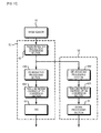
- Fig. 5A shows only a configuration relating to resolution conversion and included in the image processing circuit 6 in the embodiment of the present invention.
- a signal SG41 that has not undergone resolution conversion is fed from the defect correction circuit 5 to the phase retention resolution conversion section 42 through an input terminal 41.
- the signal SG41 is a signal in which color signals exist in a color array corresponding to the color array in the image sensor 3.
- a control signal specifying a conversion rate for resolution conversion is fed through a terminal 43.
- the specified conversion rate is associated with a resolution needed in the information processing system.
- the phase retention resolution conversion section 42 does not perform thinning. In a circumstance in which the number of pixels in the image sensor 3 rapidly increases, the maximum resolution is not always requested. A user can therefore designate a desired resolution.
- Raw data DR is fed to the control unit 2, and also fed to the de-mosaicing processing section 44.
- the de-mosaicing processing section 44 converts a signal SG42, which represents the order of the color array in the image sensor 3, into RGB signals.
- the raw data SG41 that has not undergone resolution conversion is a signal representing, for example, (3888x2608) pixels in the color array identical to the color array in the image sensor 3.
- the output signal SG42 of the phase retention resolution conversion section 42 is a signal representing, for example, (1280x960) pixels in the color array identical to the color array in the image sensor 3.
- the output signals SG44 of the de-mosaicing processing section 44 are RGB signals representing, for example, (1280x960) pixels. Namely, each of the color signals for primary colors represents (1280 ⁇ 960) pixels.
- Image-quality correction processing including gamma correction and white balance correction is performed in the de-mosaicing processing section 44, though they are not shown in Fig. 5A .
- the output signals SG44 of the de-mosaicing processing section 44 are fed to the thin-line retention resolution conversion section 45.
- a control signal specifying a conversion rate for resolution conversion is fed to the thin-line retention resolution conversion section 45 through a terminal 46. With both the specification of the conversion rate for the phase retention resolution conversion section 42 and the specification of the conversion rate for the thin-line retention resolution conversion section 45, a desired resolution is obtained finally.
- Output signals SG45 of the thin-line retention resolution conversion section 45 are applied to an output terminal 47.
- the encoder 7 (see Fig. 1 ) is connected to the output terminal 47.
- the output signals SG45 of the thin-line retention resolution conversion section 45 are RGB signals representing, for example, (640x480) pixels.
- a linear matrix arithmetic unit is included to handle an output of the thin-line retention resolution conversion section 45.
- YC signals (for example, (4:2:2) component signals) SG48 representing, for example, (640x480) pixels are outputted from the encoder 7.
- the YC signals are recorded as a normal pickup image in the recording medium 9.
- the resolution conversion sections are separately disposed in stages preceding and succeeding the de-mosaicing processing section 44.
- the signal SG42 representing a color array
- a signal SG51 representing (640x480) pixels in a color array and acting as thumbnail image data DT
- imaging information (not shown) are recorded in the recording medium 9.
- RGB signals SG53 representing, for example, (320x240) pixels are produced from the signal SG51.
- the RGB signals SG53 are image signals representing an adjusted partly enlarged image (displayed within the sub-windows M2, M3, and M5).
- RGB signals representing (640x480) pixels and being produced from the signal SG42 are employed.
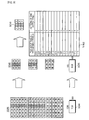
- Fig. 6 is a diagram for use in explaining processing to be performed by the phase retention resolution conversion section 42.
- the signal SG41 that has not undergone resolution conversion is a signal representing a color array corresponding to the color array in the image sensor 3 which is the Bayer array having, for example, green pixels arranged checkerwise (in the form of a five-square lattice pattern).
- an image having (18x18) pixels and having each pixel represented by binary data (pixels expressed with hatched squares are driven to a high level, and pixels expressed with squares that are not hatched are driven to a low level) will be taken as an example.
- a binary image is taken for instance in order to express the concept. Every digital signal processing is a superposition of binary operations, and apparently lies in an extension of the concept.
- the phase retention resolution conversion section 42 multiplies five pixel values, which exist in a horizontal direction and a vertical direction, by coefficients (1,0,2,0,1), calculates a 1/4 of the result of the multiplication, rounds the quarter, and performs 1/3 thinning processing.
- the signal SG42 representing (1280x960) pixels in a color array is obtained from the signal SG41 representing (3888x2608) pixels.
- resolution conversion is performed with the color array retained.
- the de-mosaicing processing section 44 performs, as shown in Fig. 7 , de-mosaicing processing on the output signal SG42 of the phase retention resolution conversion section 42.
- the de-mosaicing processing determines output pixels by majority vote using an own pixel and eight ambient pixels.
- Signals SG44 having undergone de-mosaicing processing are RGB signals.
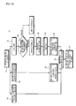
- Fig. 8 shows an example of majority-decision processing to be performed in a case where pixel values are binary (a high level and a low level).
- step S5 the ambient pixels are designated.
- step S10 If a decision is made at step S5 that eight ambient pixels have already been designated in an area (3x3) with the pixel concerned as a center, whether the variable is larger than 1 (h>1) is decided at step S10. If not, it means that the number of low-level pixels is larger than the number of high-level pixels among the pixel concerned and the pixels out of the eight ambient pixels having the same color as the output color.
- step S11 an output is set to the variable 1 (low level). If the variable h is larger than 1 (h>1), it means that the number of high-level pixels is larger than the number of low-level pixels among a total of nine pixels including the pixel concerned and eight ambient pixels. At step S12, an output is set to the variable h (low level).
- the signal representing the color array in the image sensor 3 is converted into RGB signals.
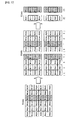
- the RGB signals SG44 sent from the de-mosaicing processing section 44 are fed to the thin-line retention resolution conversion section 45, and subjected to thin-line retention resolution conversion processing like the one shown in Fig. 9 .
- Fig. 9 shows an example in which 1/2 resolution conversion is performed and the resolution conversion is achieved through pattern recognition.
- a table which is shown in Fig. 9 and in which values are specified in advance by performing pattern recognition for fear thin lines may disappear signifies that a value of one output pixel is determined based on a pattern of two input pixels and two ambient pixels.
- the second and third bits of four-bit data correspond to the input pixels.
- RGB signals SG45 exhibiting a halved resolution are obtained. Owing to the resolution conversion through pattern recognition, thin lines in an image having undergone the conversion will not disappear. Further, the RGB signals SG45 are converted into YC signals (for brevity's sake, a Y signal alone is shown) SG48.
- signals SG44b into which the R signal SG44a having undergone de-mosaicing processing is decomposed in units of pixels concerned (2x2) are produced.
- Ambient pixels are located on the perimeter of the area of the pixels concerned.
- four pixels R10, R11, R12, and R13
- the pixels R10 and R13 are ambient pixels
- the pixels R11 and R12 are the pixels concerned.
- the four pixels have values (0001).
- the values of four pixels on one row including the pixels concerned R13 and R14 are (0100).
- two pixels are designated while do not overlap.
- the values of four pixels lined in the horizontal direction are converted into one output pixel according to the table shown in Fig. 9 in order to produce a signal SG44c having 1/2 resolution conversion performed in the horizontal direction. For example, since (0001) is converted into (0), the pixels R11 and R12 are converted into a pixel R11 having the value (0). Since (0100) is converted into (1), the pixels R13 and R14 are converted into a pixel R13 having the value (1).
- the resolution is, as shown in Fig. 11 , converted in the vertical direction into a 1/2 resolution.
- the signal SG44c having the resolution converted in the horizontal direction into the 1/2 resolution through the foregoing processing is produced from the signal SG44a.
- the values of four pixels (two pixels concerned and two ambient pixels) lined in the vertical direction are converted into one output pixel according to the table shown in Fig. 9 , whereby a signal SG44d having 1/2 resolution conversion performed in the vertical direction is produced.
- the signal SG44d has the resolution converted into a 1/4 of the resolution of the input signal SG44a. In the signal SG44d having undergone resolution conversion, a thin line represented by the input signal SG44a is not lost but is preserved.
- pixels are lined in the vertical direction, the pixels R01 and R31 are ambient pixels, and the pixels R11 and R21 are pixels concerned.
- the values of the four pixels are (0000).
- the values of four pixels on one row including the pixels concerned R13 and R23 are (1111).
- the four pixels are converted into one output pixel according to the table shown in Fig. 9 .
- the pixels R11 and R21 are converted into a pixel R11 having the value (0).
- (1111) are converted into (1)
- the pixels R13 and R23 are converted into a pixel R13 having the value (1).
- thin-line retention resolution conversion is performed on the other color signals (G signal and B signal) in the same manner as it is on the foregoing R signal.
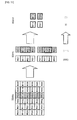
- Fig. 12 comprehensively shows the foregoing pieces of resolution conversion processing in the embodiment of the present invention.
- an output signal SG41 of the image sensor 3, and signals SG41' that are color components into which the signal SG41 is decomposed are shown.
- Phase retention resolution conversion processing is performed in units of a color component, and a signal SG42 having undergone 1/3 thinning is obtained.
- a region (6x6) in the signal SG41 is reduced to a region (2x2).
- De-mosaicing processing is performed on the signal SG42, whereby RGB signals SG44 are obtained. Further, signals SG45 having undergone 1/2 thinning are obtained by performing thin-line retention resolution conversion processing through pattern recognition. The signals SG45 have a resolution decreased to a 1/6 of the resolution of the signal SG41 that has not undergone the processing. In the signals SG45, a pattern of originally existent thin lines is not lost but is preserved even after the resolution conversion. Namely, degradation in image quality derived from the resolution conversion can be suppressed.
- the phase retention resolution conversion section 42 is disposed in a stage preceding the de-mosaicing processing section 44, and performs 1/3 thinning in the horizontal and vertical directions. Therefore, a de-mosaicing processing time can be reduced to a 1/9. In this case, an effect of a reduction in an amount of information is expected to be nearly nine times larger.
- simple filtering processing is taken as an example of phase retention resolution conversion.
- a bilinear method, a bi-cubic method, a Lanczos method, or any other existing phase retention resolution conversion technique may be adopted.
- simple majority decision processing is taken as an example of de-mosaicing, a total variation method or any other existing de-mosaicing technique may be adopted.
- each pixel is described to be one bit long for brevity's sake. Even when each pixel is 16 bits long, the aforesaid thin-line retention resolution conversion can be applied in the same manner.
- Another example of thin-line retention resolution conversion to be applied to the pixel of 16 bits long will be described below with reference to Fig. 13 and Fig. 14 .
- an original image 71 is fed to a bi-cubic resolution conversion section 72, a pattern recognition section 73, and a weighting-coefficient arithmetic section 74.
- Both a bi-cubic-resolution conversion completed image (16 bits) 75 sent from the bi-cubic resolution conversion section 72 and a weighting coefficient sent from the weighting-coefficient arithmetic section 74 are fed to a weighting arithmetic section 76.
- the certainty of pattern recognition is assessed based on the signal level of a pixel concerned, and weighting is carried out.
- the resultant image is synthesized with the bi-cubic-resolution conversion completed image.
- a relatively wide range of ambient pixels are compared with the pixel concerned by a ⁇ filter 77 (step 78). If the pixel concerned is relatively higher, "1" signifying binary thin-line retention resolution conversion is adopted. If the pixel concerned is lower, "0" is adopted. An original image (1 bit) 79 ensues.
- a pattern recognition section 80 After binary coding is completed, a pattern recognition section 80 performs pattern recognition according to a process similar to the one described with reference to Fig. 10 and Fig. 11 .
- the pattern recognition provides a pattern-recognition conversion completed image (1 bit) 81.
- the certainty of the pattern recognition is assessed by the weighting coefficient arithmetic section 74.
- the processing of the weighting coefficient arithmetic section 74 is shown in Fig. 14A and Fig. 14B .
- the certainty of each of all pixels in a binary-coded image, which is regarded as a binary-coded pattern, (the axis of abscissas) is assessed based on the signal level (the axis of ordinates) of an associated pixel in the original image.
- the certainties of all pixels employed in pattern recognition are assessed, and the total product is regarded as the certainty of all patterns.
- the certainty is used as a coefficient, and a binary image 81 having undergone the pattern recognition is multiplied by the coefficient.
- the result of the multiplication and the result of processing performed by the bi-cubic resolution conversion section 72 are added up and normalized, whereby an image (16 bits) having undergone thin-line retention resolution conversion is obtained.
- Resolution conversion processing in the embodiment of the present invention can prevent degradation in image quality compared with that performed in the configuration shown in Fig. 15A as the reference example.
- the configuration shown in Fig. 15A feeds a signal S61, which is fed from an image sensor to an input terminal 61, to a raw data generation circuit, also feeds the signal to a de-mosaicing processing section 62, and produces RGB signals SG62.
- the RGB signals SG62 are fed to a phase retention resolution conversion section 63, and thinned to approximately 1/6 signals.
- Output signals SG63 are produced.
- a control signal specifying a resolution is fed to the phase retention resolution conversion section 63 through a terminal 64.
- the signal SG61 that has not undergone resolution conversion is a signal representing, for example, (3888x2608) pixels in a color array corresponding to the color array in the image sensor 3.
- the output signals SG62 of the de-mosaicing processing section 62 are RGB signals representing, for example, (3888x2608) pixels.
- the output signals SG63 of the phase retention resolution conversion section 63 are RGB signals representing, for example, (640x480) pixels.
- YC signals (component signals) SG66 representing, for example, (640x480) pixels are outputted from an encoder.
- the YC signals are pickup image signals.
- YC signals component signals
- SG66 representing (640x480) pixels
- the signal (raw data) SG61 representing the color array
- a signal SG67 representing (777x512) pixels in the color array and serving as thumbnail image data
- imaging information (not shown) are recorded in a recording medium.
- RGB signals SG68 representing, for example, (388x260) pixels are produced from the signal SG67.
- the RGB signals SG68 are image signals representing an adjusted and partially enlarged image.
- the RGB signals SG62 representing (3888x2608) pixels and being produced from the signal SG61 are employed.
- Fig. 16 comprehensively shows the processing of resolution conversion performed by the configuration shown in Fig. 15A .
- Fig. 16 shows signals SG61' that are color components into which the output signal SG61 of the image sensor 3 is decomposed. De-mosaicing processing is performed on the signal SG61 in units of a color, whereby the RGB signals SG62 are obtained. Further, the signals SG63 produced by thinning the RGB signals into 1/6 signals are provided by the phase retention resolution conversion section 63. The signals SG63 have a resolution obtained by decreasing the resolution of the signal SG61, which has not undergone the processing, into a 1/6.
- the phase retention resolution conversion section 63 multiplies the values of pixels of a predetermined color, which exist in the horizontal direction (vertical direction), by coefficients (1,1,2,2,1,1), calculates a 1/8 of each of the results of the multiplication, rounds the results of the calculations, and thus performs 1/6 thinning processing.
- the signals SG63 represent an image in which thin lines existent in an image represented by the signals SG62 disappear and which has a resolution greatly degraded.
- the output signals SG45 obtained in the embodiment of the present invention are shown for comparison in Fig. 16 . In the signals SG45, the pattern of thin lines is not lost but is preserved despite the resolution conversion.
- de-mosaicing processing and phase retention resolution conversion processing are performed on a signal representing the same number of pixels as the number of pixels in the image sensor.
- a long processing time is required and continuous-shooting speed performance is degraded.
- an amount of information carried by a signal and recorded in a recording medium is so large that it takes much time to achieve processing of recording or reproducing or processing to be performed by an information processing system.
- the present invention is advantageous in that it is not confronted with these problems.
- a thin-line retention resolution conversion section may be substituted for the phase retention resolution conversion section 63.
- an amount of processing such as pattern recognition becomes enormous. A long processing time is required.
- the advantage provided by the inclusion of the thin-line retention resolution conversion section is limited.
- the aforesaid signal processing in accordance with the present invention is performed in both or one of a signal processing unit 52 included in an imaging apparatus, to which a pickup signal of an image sensor 51 is fed, and an information processing system (computer) 53 as shown in Fig. 17 .
- the pickup signal is inputted to the phase retention resolution conversion section 42 included in the signal processing unit 52.
- the output signal of the phase retention resolution conversion unit 42 is inputted to de-mosaicing processing sections 44A and 44B.
- data having undergone thinning and having been processed by the de-mosaicing processing section 44A and a thin-line retention resolution conversion section 45A is fed to an encoder 54, subjected to compression and encoding, for example, JPEG-conformable processing, and then outputted.
- data thinned by the phase retention resolution conversion section 42 is processed by the de-mosaicing processing section 44B and a thin-line retention resolution conversion section 45B.
- the embodiment of the present invention has been concretely described so far.
- the present invention is not limited to the aforesaid embodiment, but can be modified in various manners on the basis of the technological idea of the invention.
- a description has been made of a case where the results of imaging acquired by a digital still camera are outputted to a recording medium and processed by a computer.
- the present invention is not limited to this case, but can be applied to a case where data is outputted to the computer by utilizing data communication such as radiocommunication, and then processed.
- the color array in an image sensor has been described to have green pixels arranged checkerwise. An image sensor adopting any other color array may be employed.
- the present invention is not limited to this case, but may be applied to a case where a video camera or a portable cellular phone with a camera is used to acquire the results of imaging that are still images.
- the present invention is not limited to this case, but may be applied to a case where a dedicated processing system is used to process the results of imaging.
Landscapes
- Engineering & Computer Science (AREA)
- Multimedia (AREA)
- Signal Processing (AREA)
- Physics & Mathematics (AREA)
- General Physics & Mathematics (AREA)
- Theoretical Computer Science (AREA)
- Spectroscopy & Molecular Physics (AREA)
- Studio Devices (AREA)
- Television Signal Processing For Recording (AREA)
- Color Television Image Signal Generators (AREA)
Applications Claiming Priority (2)
| Application Number | Priority Date | Filing Date | Title |
|---|---|---|---|
| JP2007151090 | 2007-06-07 | ||
| PCT/JP2008/060718 WO2008150017A1 (ja) | 2007-06-07 | 2008-06-05 | 信号処理方法および信号処理装置 |
Publications (2)
| Publication Number | Publication Date |
|---|---|
| EP2157802A1 true EP2157802A1 (de) | 2010-02-24 |
| EP2157802A4 EP2157802A4 (de) | 2015-04-01 |
Family
ID=40093818
Family Applications (1)
| Application Number | Title | Priority Date | Filing Date |
|---|---|---|---|
| EP08765489.3A Withdrawn EP2157802A4 (de) | 2007-06-07 | 2008-06-05 | Signalverarbeitungsverfahren und signalverarbeitungsgerät |
Country Status (6)
| Country | Link |
|---|---|
| US (1) | US8269850B2 (de) |
| EP (1) | EP2157802A4 (de) |
| JP (1) | JP5240194B2 (de) |
| KR (1) | KR20100017626A (de) |
| CN (1) | CN101682788B (de) |
| WO (1) | WO2008150017A1 (de) |
Families Citing this family (11)
| Publication number | Priority date | Publication date | Assignee | Title |
|---|---|---|---|---|
| WO2010080646A2 (en) * | 2009-01-12 | 2010-07-15 | Maxim Integrated Products, Inc. | Video acquisition and processing systems |
| US8988458B2 (en) * | 2010-04-13 | 2015-03-24 | At&T Intellectual Property I, L.P. | System and method for generating media thumbscapes |
| CN101957999A (zh) * | 2010-09-01 | 2011-01-26 | 汉王科技股份有限公司 | 图像处理方法、装置和系统 |
| US8610797B2 (en) * | 2010-12-20 | 2013-12-17 | Panasonic Corporation | Image processing device, imaging device, and image processing method |
| JP5845464B2 (ja) * | 2011-05-31 | 2016-01-20 | パナソニックIpマネジメント株式会社 | 画像処理装置及び画像処理方法並びにデジタルカメラ |
| CN102799385B (zh) * | 2012-07-19 | 2016-12-21 | 腾讯科技(深圳)有限公司 | 桌面控制方法和装置 |
| CN104823216B (zh) * | 2012-11-13 | 2018-06-29 | 日本电气株式会社 | 图像处理装置、图像处理方法和程序 |
| JP6108831B2 (ja) * | 2012-12-28 | 2017-04-05 | オリンパス株式会社 | 携帯機器、サーバ、画像生成方法およびプログラム |
| US9652867B2 (en) * | 2013-10-18 | 2017-05-16 | Apple Inc. | Grain generation and blending |
| JP6381219B2 (ja) * | 2014-02-06 | 2018-08-29 | キヤノン株式会社 | 画像処理装置、画像処理方法、及びプログラム |
| KR102709671B1 (ko) * | 2019-08-08 | 2024-09-26 | 에스케이하이닉스 주식회사 | 이미지 센서, 이미지 신호 프로세서 및 이들을 포함하는 이미지 처리 시스템 |
Family Cites Families (19)
| Publication number | Priority date | Publication date | Assignee | Title |
|---|---|---|---|---|
| JPH02177766A (ja) * | 1988-12-28 | 1990-07-10 | Canon Inc | 2値画像の階層的符号化方式 |
| JP3230291B2 (ja) | 1992-09-07 | 2001-11-19 | キヤノン株式会社 | 画像再生装置及びその方法 |
| US5619596A (en) * | 1993-10-06 | 1997-04-08 | Seiko Instruments Inc. | Method and apparatus for optical pattern recognition |
| JP3623990B2 (ja) * | 1993-10-28 | 2005-02-23 | キヤノン株式会社 | 画像処理方法及び装置 |
| US6118457A (en) * | 1993-10-28 | 2000-09-12 | Canon Kabushiki Kaisha | Resolution conversion with preservation of fine lines and of hue |
| JPH08101911A (ja) * | 1994-09-30 | 1996-04-16 | Canon Inc | 画像記録装置 |
| JP3483426B2 (ja) | 1997-04-28 | 2004-01-06 | 大日本スクリーン製造株式会社 | 画像縮小方法及びプログラムを記録した記憶媒体 |
| JP3557099B2 (ja) | 1998-07-15 | 2004-08-25 | 日本電信電話株式会社 | 2色画像縮小変換方法および装置およびこの方法を記録した記録媒体 |
| JP3654420B2 (ja) | 2000-02-25 | 2005-06-02 | インターナショナル・ビジネス・マシーンズ・コーポレーション | 画像変換方法、画像処理装置、および画像表示装置 |
| JP2002027315A (ja) | 2000-07-07 | 2002-01-25 | Sony Corp | 動き検出装置及び動き検出方法 |
| JP5108172B2 (ja) | 2000-09-06 | 2012-12-26 | 株式会社ニコン | 画像データサイズ変換処理装置、電子スチルカメラ、および画像データサイズ変換処理用記録媒体 |
| US20030222998A1 (en) * | 2000-12-20 | 2003-12-04 | Satoru Yamauchi | Digital still camera system and method |
| JP4096626B2 (ja) | 2002-05-29 | 2008-06-04 | 富士フイルム株式会社 | 画像処理方法及び画像処理プログラム |
| JP4497945B2 (ja) * | 2003-02-04 | 2010-07-07 | キヤノン株式会社 | 撮像装置 |
| JP4420440B2 (ja) * | 2004-02-19 | 2010-02-24 | 株式会社リコー | 画像処理装置、画像処理方法、文字認識装置、プログラムおよび記録媒体 |
| JP3915795B2 (ja) * | 2004-03-29 | 2007-05-16 | コニカミノルタビジネステクノロジーズ株式会社 | 画像処理装置および画像処理プログラム |
| JP2006060585A (ja) * | 2004-08-20 | 2006-03-02 | Fuji Photo Film Co Ltd | デジタルカメラ |
| JP2006303693A (ja) * | 2005-04-18 | 2006-11-02 | Nikon Corp | 縮小画像の生成機能を備える電子カメラ |
| JP2006340120A (ja) * | 2005-06-03 | 2006-12-14 | Sony Corp | 撮像装置、撮像結果の処理方法、画像処理装置、撮像結果の処理方法のプログラム、撮像結果の処理方法のプログラムを記録した記録媒体及び撮像結果の処理システム |
-
2008
- 2008-06-05 US US12/451,924 patent/US8269850B2/en not_active Expired - Fee Related
- 2008-06-05 CN CN2008800192184A patent/CN101682788B/zh not_active Expired - Fee Related
- 2008-06-05 JP JP2009517927A patent/JP5240194B2/ja not_active Expired - Fee Related
- 2008-06-05 WO PCT/JP2008/060718 patent/WO2008150017A1/ja not_active Ceased
- 2008-06-05 EP EP08765489.3A patent/EP2157802A4/de not_active Withdrawn
- 2008-06-05 KR KR1020097025362A patent/KR20100017626A/ko not_active Withdrawn
Also Published As
| Publication number | Publication date |
|---|---|
| WO2008150017A1 (ja) | 2008-12-11 |
| CN101682788A (zh) | 2010-03-24 |
| KR20100017626A (ko) | 2010-02-16 |
| JP5240194B2 (ja) | 2013-07-17 |
| EP2157802A4 (de) | 2015-04-01 |
| US8269850B2 (en) | 2012-09-18 |
| US20100118186A1 (en) | 2010-05-13 |
| CN101682788B (zh) | 2012-02-15 |
| JPWO2008150017A1 (ja) | 2010-08-26 |
Similar Documents
| Publication | Publication Date | Title |
|---|---|---|
| US8269850B2 (en) | Signal processing method and signal processing system | |
| US7916208B2 (en) | Image processor, digital camera, and method for processing image data | |
| EP2193656B1 (de) | Mehrfachbelichtungsmuster zur erweiterung des dynamikumfangs von bildern | |
| US8896722B2 (en) | Image data processing apparatus and electronic camera | |
| JP4375448B2 (ja) | 画像処理装置、撮像装置、画像処理方法およびプログラム | |
| US8350926B2 (en) | Imaging apparatus, method of processing imaging result, image processing apparatus, program of imaging result processing method, recording medium storing program of imaging result processing method, and imaging result processing system | |
| US20080013787A1 (en) | Imaging apparatus, image processor, image filing method, image processing method and image processing program | |
| US20090160992A1 (en) | Image pickup apparatus, color noise reduction method, and color noise reduction program | |
| US20100194911A1 (en) | Image data generating apparatus, method and program | |
| EP2573758B1 (de) | Verfahren und Vorrichtung zur Anzeige eines zusammenfassenden Videos | |
| WO2009060970A1 (ja) | 信号処理装置及び信号処理プログラム | |
| US20060029287A1 (en) | Noise reduction apparatus and method | |
| US10397587B2 (en) | Image processing apparatus and control method thereof | |
| JP3649468B2 (ja) | 撮影機能付き電子アルバムシステム | |
| JP2002305684A (ja) | 撮像システム及びプログラム | |
| JP5092536B2 (ja) | 画像処理装置及びそのプログラム | |
| JP2008294524A (ja) | 画像処理装置および画像処理方法 | |
| CN106412391B (zh) | 图像处理设备、图像处理方法和摄像设备 | |
| US6677994B1 (en) | Image processing apparatus method of the same and camera apparatus | |
| WO2022158318A1 (ja) | 撮像装置、撮像装置の制御方法および制御プログラム | |
| US20130321658A1 (en) | Image capture apparatus and method of controlling the same | |
| JP2021078051A (ja) | 画像処理装置および画像制御方法、プログラム、並びに記憶媒体 | |
| KR101378328B1 (ko) | 디지털 영상 처리 방법 | |
| CN114514743A (zh) | 服务器装置及程序 | |
| JP2003264735A (ja) | 画像処理システム、画像処理方法、コンピュータプログラム及びコンピュータ読み取り可能な記録媒体 |
Legal Events
| Date | Code | Title | Description |
|---|---|---|---|
| PUAI | Public reference made under article 153(3) epc to a published international application that has entered the european phase |
Free format text: ORIGINAL CODE: 0009012 |
|
| 17P | Request for examination filed |
Effective date: 20091207 |
|
| AK | Designated contracting states |
Kind code of ref document: A1 Designated state(s): AT BE BG CH CY CZ DE DK EE ES FI FR GB GR HR HU IE IS IT LI LT LU LV MC MT NL NO PL PT RO SE SI SK TR |
|
| AX | Request for extension of the european patent |
Extension state: AL BA MK RS |
|
| DAX | Request for extension of the european patent (deleted) | ||
| STAA | Information on the status of an ep patent application or granted ep patent |
Free format text: STATUS: THE APPLICATION HAS BEEN WITHDRAWN |
|
| RA4 | Supplementary search report drawn up and despatched (corrected) |
Effective date: 20150304 |
|
| RIC1 | Information provided on ipc code assigned before grant |
Ipc: H04N 9/07 20060101AFI20150226BHEP Ipc: H04N 9/04 20060101ALI20150226BHEP Ipc: H04N 5/347 20110101ALI20150226BHEP Ipc: H04N 5/232 20060101ALI20150226BHEP Ipc: G06T 3/40 20060101ALI20150226BHEP Ipc: H04N 1/387 20060101ALI20150226BHEP Ipc: H04N 101/00 20060101ALI20150226BHEP |
|
| 18W | Application withdrawn |
Effective date: 20150306 |