EP2154684A1 - Aufzeichnungsbandkassette - Google Patents
Aufzeichnungsbandkassette Download PDFInfo
- Publication number
- EP2154684A1 EP2154684A1 EP09010039A EP09010039A EP2154684A1 EP 2154684 A1 EP2154684 A1 EP 2154684A1 EP 09010039 A EP09010039 A EP 09010039A EP 09010039 A EP09010039 A EP 09010039A EP 2154684 A1 EP2154684 A1 EP 2154684A1
- Authority
- EP
- European Patent Office
- Prior art keywords
- reel
- case
- recording tape
- lock
- face
- Prior art date
- Legal status (The legal status is an assumption and is not a legal conclusion. Google has not performed a legal analysis and makes no representation as to the accuracy of the status listed.)
- Granted
Links
- 230000033001 locomotion Effects 0.000 claims abstract description 43
- 238000006073 displacement reaction Methods 0.000 claims description 24
- 230000014759 maintenance of location Effects 0.000 claims description 23
- 230000002093 peripheral effect Effects 0.000 claims description 18
- 230000000717 retained effect Effects 0.000 claims description 15
- 238000003825 pressing Methods 0.000 claims description 10
- 230000007246 mechanism Effects 0.000 claims description 8
- 238000003780 insertion Methods 0.000 claims description 6
- 230000037431 insertion Effects 0.000 claims description 6
- 230000006835 compression Effects 0.000 abstract description 33
- 238000007906 compression Methods 0.000 abstract description 33
- 238000000926 separation method Methods 0.000 description 11
- 238000003466 welding Methods 0.000 description 7
- 238000004804 winding Methods 0.000 description 5
- 230000009471 action Effects 0.000 description 4
- 230000000052 comparative effect Effects 0.000 description 4
- 238000010586 diagram Methods 0.000 description 4
- 238000000465 moulding Methods 0.000 description 4
- 229920005989 resin Polymers 0.000 description 4
- 239000011347 resin Substances 0.000 description 4
- 239000002184 metal Substances 0.000 description 3
- 238000013459 approach Methods 0.000 description 2
- 230000008859 change Effects 0.000 description 2
- 210000000078 claw Anatomy 0.000 description 2
- 230000007547 defect Effects 0.000 description 2
- 239000004417 polycarbonate Substances 0.000 description 2
- 229920006324 polyoxymethylene Polymers 0.000 description 2
- 229910001220 stainless steel Inorganic materials 0.000 description 2
- 239000010935 stainless steel Substances 0.000 description 2
- 229930182556 Polyacetal Natural products 0.000 description 1
- 238000002788 crimping Methods 0.000 description 1
- 230000000694 effects Effects 0.000 description 1
- 230000008030 elimination Effects 0.000 description 1
- 238000003379 elimination reaction Methods 0.000 description 1
- 238000005516 engineering process Methods 0.000 description 1
- 239000000835 fiber Substances 0.000 description 1
- 230000006872 improvement Effects 0.000 description 1
- 230000002452 interceptive effect Effects 0.000 description 1
- 238000005304 joining Methods 0.000 description 1
- 239000000696 magnetic material Substances 0.000 description 1
- 229920000515 polycarbonate Polymers 0.000 description 1
- 229920005672 polyolefin resin Polymers 0.000 description 1
- 230000009467 reduction Effects 0.000 description 1
- 230000002787 reinforcement Effects 0.000 description 1
- 230000000630 rising effect Effects 0.000 description 1
- 238000003860 storage Methods 0.000 description 1
Images


Classifications
-
- G—PHYSICS
- G11—INFORMATION STORAGE
- G11B—INFORMATION STORAGE BASED ON RELATIVE MOVEMENT BETWEEN RECORD CARRIER AND TRANSDUCER
- G11B23/00—Record carriers not specific to the method of recording or reproducing; Accessories, e.g. containers, specially adapted for co-operation with the recording or reproducing apparatus ; Intermediate mediums; Apparatus or processes specially adapted for their manufacture
- G11B23/02—Containers; Storing means both adapted to cooperate with the recording or reproducing means
- G11B23/04—Magazines; Cassettes for webs or filaments
- G11B23/041—Details
- G11B23/043—Brakes for tapes or tape reels
-
- G—PHYSICS
- G11—INFORMATION STORAGE
- G11B—INFORMATION STORAGE BASED ON RELATIVE MOVEMENT BETWEEN RECORD CARRIER AND TRANSDUCER
- G11B23/00—Record carriers not specific to the method of recording or reproducing; Accessories, e.g. containers, specially adapted for co-operation with the recording or reproducing apparatus ; Intermediate mediums; Apparatus or processes specially adapted for their manufacture
- G11B23/02—Containers; Storing means both adapted to cooperate with the recording or reproducing means
- G11B23/04—Magazines; Cassettes for webs or filaments
- G11B23/08—Magazines; Cassettes for webs or filaments for housing webs or filaments having two distinct ends
- G11B23/107—Magazines; Cassettes for webs or filaments for housing webs or filaments having two distinct ends using one reel or core, one end of the record carrier coming out of the magazine or cassette
Definitions
- Recording tape cartridges are known that lock rotation of a reel relative to a case by meshing a brake gear, formed at the outer periphery of a brake member that is not rotatable with respect to the case, with an engaged gear formed at the inner periphery of the reel hub. Recording tape cartridges are also known that, by introducing a lock member between a reel and a case top panel, restrict displacement of the reel in with respect to the case in the reel axial direction.
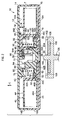
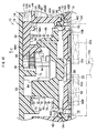
- a gap G (see FIG. 7 ) is formed between the top panel 14A and the top end face of the circular cylindrical portion 42A configuring the top end of the reel 40 (the top face of the top flange 44), with the gap G having a separation distance W along the reel 40 axial direction.
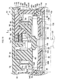
- the reel 40 is rotationally driven by the rotation shaft 100, the reel 40 is raised within the case 12, as shown in FIG. 3 , so as to rotate without contact with any portion of the case 12.
- the position of the reel 40 in this state will be referred to as the raised position.
- the lock member 90 is configured to adopt, while moving sliding against the top panel 14A in the radial direction, a restricting position (see FIG. 2 ) in which the lock portion 93 is inserted into the gap G and the reel 40 is restricted from rising from the lowest position, and a restriction released position (see FIG. 3 ) where the lock portion 93 is withdrawn from the gap G and movement of the reel 40 is permitted from the lowest position toward the raised position.
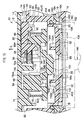
- the thickness D of the lock portion 93 is set slightly smaller than the separation distance W of the gap G (D ⁇ W), and, as shown in FIG.
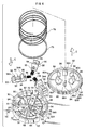
- respective retention projections 70 project between each of the ring shaped walls 62, 64 and between the edges of the cut away portions 62A, 64A.
- Each of the retention projections 70 is positioned on a line extending from each of the corresponding guide walls 65, and an engagement protrusion 70A is provided at the bottom end of the respective retention projection 70, extending out below the accommodating portions 63.
- the bottom end at the side that faces the engagement protrusion 70A on the other side of each of the engagement protrusions 70A is a tapered face, so as to engage the lock member 90 at the corner portion of the body portion 92 when assembled from below.
- stopper ribs 74 project from the top panel 14A at the outside of the ring shaped wall 62, the stopper ribs 74 being along a circular circumference coaxial to the ring shaped wall 62.
- Each of the stopper ribs 74 is disposed to the radial direction outside of the respective accommodating portion 63, and is used for stopping the lock member 90 in the interim.
- Each of the stopper ribs 74 is disposed just further to the radial direction outside than the radial direction outside end of the lock portion 93 of the lock member 90 positioned in the restricting position.
- the separation distance between the radial direction outside end of the lock portions 93 in this state and the stopper ribs 74 is slightly smaller than a projected length of the tapered face 96A onto a horizontal plane (a plane orthogonal to the reel axial direction).
- the stopper ribs 74 are made to project from the top panel 14A with a height suppressed low enough so that they do not interfere with the reel 40 positioned in the raised position.
- the reel 40 In the assembled state, namely in the shipping state that is a not-in-use state, as shown in FIG. 2 and FIG. 9 , the reel 40 is positioned in the lowest position due to biasing force of the compression coil spring 78, the brake member 80 is positioned in the rotation locking position due to biasing force of the compression coil spring 78, and each of the lock members 90 is positioned in the restricting position due to biasing force of the compression springs 56. Consequently, the reel 40 positioned in the lowest position is prevented from rotating with respect to the case 12 by the brake member 80, and also movement in the axial direction with respect to the case 12, namely movement toward the raised position, is restricted by each of the lock members 90.
- the state of the recording tape cartridge 10 is referred to as being the not-in-use state.
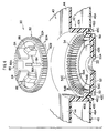
- each of the lock members 90 In the in-use state the respective cam portion 94 of each of the lock members 90 is inserted to the inside of the corresponding engagement projection 86 of the brake member 80, such that radial direction outward facing face of each of the cam portion 94 abuts the radial direction inward facing face of the corresponding engagement projection 86.
- the radial direction outward facing face of each of the cam portions 94 of each of the lock members 90 and the radial direction inward facing face of each of the engagement projections 86 of the brake member 80 have respective draft angles of substantially 0°, a configuration such that no component of force acting in the reel 40 axial direction arises due to biasing force from the compression coil spring 78 and the compression spring 56 when in the in-use state.
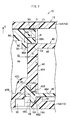
- configuration is made such that from all of the faces of the reel 40 facing up or down, only the top end face of the circular cylindrical portion 42A positioned in the range of the thickness Tr of the circular cylindrical portion 42A (between the inside and outside peripheral faces thereof), and the bottom end face of the ring shaped rib 46C contact, or become very close to contact, with the lock portion 93 of the respective lock members 90 or the contact surface 16C of the case 12.
- configuration is made such that movement restricting force in the up-down direction, to restrict up or down movement when the reel 40 attempts to move up or down, only acts on the portions of the reel 40 in the range of the thickness Tr of the circular cylindrical portion 42A.
- the recording tape cartridge 10 is loaded front wall 12A side first into a bucket (not illustrated in the drawings) of the drive device.
- an opening and closing member of the drive device presses a portion on the door 30 further to the right than the support shafts 26.
- the door 30 is thereby rotated about the support shafts 26 as the center of rotation against biasing force of the torsion spring 28, and the opening 20 is opened.
- the drive device rotationally drives the take-up reel and the rotation shaft 100, namely the reel 40, in synchronization with each other.
- the magnetic tape T is thereby progressively fed out to the drive device side. Data is then recorded on the magnetic tape T, or data recorded on the magnetic tape T is reproduced, by a recording and reproducing head (not illustrated in the drawings) disposed along a specific tape path of the drive device.
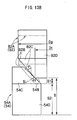
- tapered portions 54B, 82B are respectively formed to the engaged gear 54 and the brake gear 82, when the brake member 80 is being assembled within the reel hub 42, the tapered portions 54B, 82B guide each other together, and the brake gear 82 can be readily centered with respect to the engaged gear 54. Since tapered portions 54C, 82C are also respectively formed to the engaged gear 54 and the brake gear 82, the brake gear 82 can be readily meshed with the engaged gear 54 while being centered with respect to the engaged gear 54.
- FIG. 13C a comparative example shown in FIG. 13C .
- a brake gear 200 having a gear diameter Dg, with an taper portion start diameter D t that is equivalent to that of the brake gear 82, and external teeth 200A formed with ⁇ 1 > ⁇ 2.
- configuration was made with the top flange 44 integrally provided to the reel hub 42, however the present invention is not limited thereto.
- configuration may be made with the bottom flange 46A integrally formed to the reel hub 42, and with the top flange 44 attached to the top end face of the circular cylindrical portion 42A by ultrasonic welding or the like.
- the lock portions 93 of lock members 90 positioned in the restricting position are disposed so as to make contact with a portion of the top flange further to the radial direction inside than the outer peripheral face of the circular cylindrical portion 42A. Consequently, a cylindrical shaped portion may be formed to the top flange that is a separate body to the reel hub 42, for fitting into the circular cylindrical portion 42A.
Landscapes
- Unwinding Webs (AREA)
Applications Claiming Priority (1)
| Application Number | Priority Date | Filing Date | Title |
|---|---|---|---|
| JP2008208405A JP4927044B2 (ja) | 2008-08-13 | 2008-08-13 | 記録テープカートリッジ |
Publications (2)
| Publication Number | Publication Date |
|---|---|
| EP2154684A1 true EP2154684A1 (de) | 2010-02-17 |
| EP2154684B1 EP2154684B1 (de) | 2012-05-02 |
Family
ID=41259751
Family Applications (1)
| Application Number | Title | Priority Date | Filing Date |
|---|---|---|---|
| EP09010039A Not-in-force EP2154684B1 (de) | 2008-08-13 | 2009-08-04 | Aufzeichnungsbandkassette |
Country Status (4)
| Country | Link |
|---|---|
| US (1) | US7841554B2 (de) |
| EP (1) | EP2154684B1 (de) |
| JP (1) | JP4927044B2 (de) |
| AT (1) | ATE556409T1 (de) |
Families Citing this family (2)
| Publication number | Priority date | Publication date | Assignee | Title |
|---|---|---|---|---|
| JP5496646B2 (ja) * | 2009-12-25 | 2014-05-21 | 富士フイルム株式会社 | リール及び記録テープカートリッジ |
| JP6598751B2 (ja) | 2016-09-29 | 2019-10-30 | 富士フイルム株式会社 | 記録テープカートリッジ |
Citations (1)
| Publication number | Priority date | Publication date | Assignee | Title |
|---|---|---|---|---|
| EP1895534A1 (de) * | 2004-02-24 | 2008-03-05 | FUJIFILM Corporation | Aufzeichnungsbandkassette |
Family Cites Families (12)
| Publication number | Priority date | Publication date | Assignee | Title |
|---|---|---|---|---|
| JPH01154577U (de) * | 1988-04-11 | 1989-10-24 | ||
| US5436782A (en) * | 1992-07-13 | 1995-07-25 | U.S. Philips Corporation | Magnetic-tape cassette and reel-locking device suitable for use in the magnetic-tape cassette |
| US6113020A (en) * | 1997-07-02 | 2000-09-05 | Seagate Technology, Inc. | Reel lock and coupling engagement mechanisms for a cartridge |
| JP3614634B2 (ja) * | 1997-12-25 | 2005-01-26 | 富士写真フイルム株式会社 | 磁気テープカートリッジ |
| JP2004199808A (ja) * | 2002-12-19 | 2004-07-15 | Fuji Photo Film Co Ltd | 記録テープカートリッジ |
| JP4359470B2 (ja) * | 2003-09-09 | 2009-11-04 | 富士フイルム株式会社 | 記録テープカートリッジ |
| US7040564B1 (en) * | 2003-12-26 | 2006-05-09 | Storage Technology Corporation | Cartridge reel with internal reel assembly lock |
| US7104486B2 (en) * | 2003-12-29 | 2006-09-12 | Fuji Photo Film Co., Ltd. | Recording tape cartridge |
| JP4266210B2 (ja) * | 2004-05-24 | 2009-05-20 | 富士フイルム株式会社 | 記録テープカートリッジ |
| JP4512530B2 (ja) * | 2004-07-26 | 2010-07-28 | 富士フイルム株式会社 | 記録テープカートリッジ |
| JP4295738B2 (ja) * | 2005-03-25 | 2009-07-15 | 富士フイルム株式会社 | 記録テープカートリッジ |
| JP4597916B2 (ja) * | 2006-06-13 | 2010-12-15 | 富士フイルム株式会社 | 記録テープカートリッジ |
-
2008
- 2008-08-13 JP JP2008208405A patent/JP4927044B2/ja active Active
-
2009
- 2009-07-28 US US12/510,264 patent/US7841554B2/en active Active
- 2009-08-04 AT AT09010039T patent/ATE556409T1/de active
- 2009-08-04 EP EP09010039A patent/EP2154684B1/de not_active Not-in-force
Patent Citations (1)
| Publication number | Priority date | Publication date | Assignee | Title |
|---|---|---|---|---|
| EP1895534A1 (de) * | 2004-02-24 | 2008-03-05 | FUJIFILM Corporation | Aufzeichnungsbandkassette |
Also Published As
| Publication number | Publication date |
|---|---|
| US7841554B2 (en) | 2010-11-30 |
| US20100038466A1 (en) | 2010-02-18 |
| JP4927044B2 (ja) | 2012-05-09 |
| EP2154684B1 (de) | 2012-05-02 |
| ATE556409T1 (de) | 2012-05-15 |
| JP2010044826A (ja) | 2010-02-25 |
Similar Documents
| Publication | Publication Date | Title |
|---|---|---|
| JP4424897B2 (ja) | 記録テープカートリッジ | |
| JP3710414B2 (ja) | 記録テープカートリッジ | |
| EP2154684B1 (de) | Aufzeichnungsbandkassette | |
| JP4359470B2 (ja) | 記録テープカートリッジ | |
| JP4317149B2 (ja) | 記録テープカートリッジ | |
| JP2010061762A (ja) | 記録テープカートリッジ及び回転ロック構造 | |
| US8006930B2 (en) | Reel | |
| US7562839B2 (en) | Recording tape cartridge | |
| US20100038465A1 (en) | Recording tape cartridge | |
| JP2004199808A (ja) | 記録テープカートリッジ | |
| JP3710413B2 (ja) | 記録テープカートリッジ | |
| JP3511822B2 (ja) | テープカートリッジ | |
| JP4153275B2 (ja) | 記録テープカートリッジ | |
| JP4133666B2 (ja) | 記録テープカートリッジ | |
| JP4102849B1 (ja) | 記録テープカートリッジ | |
| JP4102846B1 (ja) | 記録テープカートリッジ | |
| JP4790506B2 (ja) | 記録テープカートリッジ | |
| JP4597916B2 (ja) | 記録テープカートリッジ | |
| JP2010061710A (ja) | 記録テープカートリッジ | |
| JP3808777B2 (ja) | 記録テープカートリッジ | |
| JP4009166B2 (ja) | 記録テープカートリッジ及びドライブ装置 | |
| EP1011104B1 (de) | Bandkassette | |
| JP4865071B2 (ja) | リール | |
| JP4201084B2 (ja) | 記録再生装置の蓋開閉装置 | |
| JP2004118884A (ja) | 記録テープカートリッジ |
Legal Events
| Date | Code | Title | Description |
|---|---|---|---|
| PUAI | Public reference made under article 153(3) epc to a published international application that has entered the european phase |
Free format text: ORIGINAL CODE: 0009012 |
|
| AK | Designated contracting states |
Kind code of ref document: A1 Designated state(s): AT BE BG CH CY CZ DE DK EE ES FI FR GB GR HR HU IE IS IT LI LT LU LV MC MK MT NL NO PL PT RO SE SI SK SM TR |
|
| AX | Request for extension of the european patent |
Extension state: AL BA RS |
|
| 17P | Request for examination filed |
Effective date: 20100810 |
|
| GRAP | Despatch of communication of intention to grant a patent |
Free format text: ORIGINAL CODE: EPIDOSNIGR1 |
|
| GRAS | Grant fee paid |
Free format text: ORIGINAL CODE: EPIDOSNIGR3 |
|
| GRAA | (expected) grant |
Free format text: ORIGINAL CODE: 0009210 |
|
| AK | Designated contracting states |
Kind code of ref document: B1 Designated state(s): AT BE BG CH CY CZ DE DK EE ES FI FR GB GR HR HU IE IS IT LI LT LU LV MC MK MT NL NO PL PT RO SE SI SK SM TR |
|
| REG | Reference to a national code |
Ref country code: GB Ref legal event code: FG4D |
|
| REG | Reference to a national code |
Ref country code: AT Ref legal event code: REF Ref document number: 556409 Country of ref document: AT Kind code of ref document: T Effective date: 20120515 Ref country code: CH Ref legal event code: EP |
|
| REG | Reference to a national code |
Ref country code: IE Ref legal event code: FG4D |
|
| REG | Reference to a national code |
Ref country code: DE Ref legal event code: R096 Ref document number: 602009006680 Country of ref document: DE Effective date: 20120621 |
|
| REG | Reference to a national code |
Ref country code: NL Ref legal event code: VDEP Effective date: 20120502 |
|
| REG | Reference to a national code |
Ref country code: LT Ref legal event code: MG4D Effective date: 20120502 |
|
| PG25 | Lapsed in a contracting state [announced via postgrant information from national office to epo] |
Ref country code: LT Free format text: LAPSE BECAUSE OF FAILURE TO SUBMIT A TRANSLATION OF THE DESCRIPTION OR TO PAY THE FEE WITHIN THE PRESCRIBED TIME-LIMIT Effective date: 20120502 Ref country code: FI Free format text: LAPSE BECAUSE OF FAILURE TO SUBMIT A TRANSLATION OF THE DESCRIPTION OR TO PAY THE FEE WITHIN THE PRESCRIBED TIME-LIMIT Effective date: 20120502 Ref country code: PL Free format text: LAPSE BECAUSE OF FAILURE TO SUBMIT A TRANSLATION OF THE DESCRIPTION OR TO PAY THE FEE WITHIN THE PRESCRIBED TIME-LIMIT Effective date: 20120502 Ref country code: IS Free format text: LAPSE BECAUSE OF FAILURE TO SUBMIT A TRANSLATION OF THE DESCRIPTION OR TO PAY THE FEE WITHIN THE PRESCRIBED TIME-LIMIT Effective date: 20120902 Ref country code: SE Free format text: LAPSE BECAUSE OF FAILURE TO SUBMIT A TRANSLATION OF THE DESCRIPTION OR TO PAY THE FEE WITHIN THE PRESCRIBED TIME-LIMIT Effective date: 20120502 Ref country code: CY Free format text: LAPSE BECAUSE OF FAILURE TO SUBMIT A TRANSLATION OF THE DESCRIPTION OR TO PAY THE FEE WITHIN THE PRESCRIBED TIME-LIMIT Effective date: 20120502 Ref country code: NO Free format text: LAPSE BECAUSE OF FAILURE TO SUBMIT A TRANSLATION OF THE DESCRIPTION OR TO PAY THE FEE WITHIN THE PRESCRIBED TIME-LIMIT Effective date: 20120802 |
|
| REG | Reference to a national code |
Ref country code: AT Ref legal event code: MK05 Ref document number: 556409 Country of ref document: AT Kind code of ref document: T Effective date: 20120502 |
|
| PG25 | Lapsed in a contracting state [announced via postgrant information from national office to epo] |
Ref country code: HR Free format text: LAPSE BECAUSE OF FAILURE TO SUBMIT A TRANSLATION OF THE DESCRIPTION OR TO PAY THE FEE WITHIN THE PRESCRIBED TIME-LIMIT Effective date: 20120502 Ref country code: LV Free format text: LAPSE BECAUSE OF FAILURE TO SUBMIT A TRANSLATION OF THE DESCRIPTION OR TO PAY THE FEE WITHIN THE PRESCRIBED TIME-LIMIT Effective date: 20120502 Ref country code: SI Free format text: LAPSE BECAUSE OF FAILURE TO SUBMIT A TRANSLATION OF THE DESCRIPTION OR TO PAY THE FEE WITHIN THE PRESCRIBED TIME-LIMIT Effective date: 20120502 Ref country code: GR Free format text: LAPSE BECAUSE OF FAILURE TO SUBMIT A TRANSLATION OF THE DESCRIPTION OR TO PAY THE FEE WITHIN THE PRESCRIBED TIME-LIMIT Effective date: 20120803 Ref country code: PT Free format text: LAPSE BECAUSE OF FAILURE TO SUBMIT A TRANSLATION OF THE DESCRIPTION OR TO PAY THE FEE WITHIN THE PRESCRIBED TIME-LIMIT Effective date: 20120903 |
|
| PG25 | Lapsed in a contracting state [announced via postgrant information from national office to epo] |
Ref country code: BE Free format text: LAPSE BECAUSE OF FAILURE TO SUBMIT A TRANSLATION OF THE DESCRIPTION OR TO PAY THE FEE WITHIN THE PRESCRIBED TIME-LIMIT Effective date: 20120502 |
|
| PGFP | Annual fee paid to national office [announced via postgrant information from national office to epo] |
Ref country code: DE Payment date: 20120820 Year of fee payment: 4 |
|
| PG25 | Lapsed in a contracting state [announced via postgrant information from national office to epo] |
Ref country code: NL Free format text: LAPSE BECAUSE OF FAILURE TO SUBMIT A TRANSLATION OF THE DESCRIPTION OR TO PAY THE FEE WITHIN THE PRESCRIBED TIME-LIMIT Effective date: 20120502 Ref country code: CZ Free format text: LAPSE BECAUSE OF FAILURE TO SUBMIT A TRANSLATION OF THE DESCRIPTION OR TO PAY THE FEE WITHIN THE PRESCRIBED TIME-LIMIT Effective date: 20120502 Ref country code: RO Free format text: LAPSE BECAUSE OF FAILURE TO SUBMIT A TRANSLATION OF THE DESCRIPTION OR TO PAY THE FEE WITHIN THE PRESCRIBED TIME-LIMIT Effective date: 20120502 Ref country code: EE Free format text: LAPSE BECAUSE OF FAILURE TO SUBMIT A TRANSLATION OF THE DESCRIPTION OR TO PAY THE FEE WITHIN THE PRESCRIBED TIME-LIMIT Effective date: 20120502 Ref country code: AT Free format text: LAPSE BECAUSE OF FAILURE TO SUBMIT A TRANSLATION OF THE DESCRIPTION OR TO PAY THE FEE WITHIN THE PRESCRIBED TIME-LIMIT Effective date: 20120502 Ref country code: DK Free format text: LAPSE BECAUSE OF FAILURE TO SUBMIT A TRANSLATION OF THE DESCRIPTION OR TO PAY THE FEE WITHIN THE PRESCRIBED TIME-LIMIT Effective date: 20120502 Ref country code: SK Free format text: LAPSE BECAUSE OF FAILURE TO SUBMIT A TRANSLATION OF THE DESCRIPTION OR TO PAY THE FEE WITHIN THE PRESCRIBED TIME-LIMIT Effective date: 20120502 |
|
| PG25 | Lapsed in a contracting state [announced via postgrant information from national office to epo] |
Ref country code: IT Free format text: LAPSE BECAUSE OF FAILURE TO SUBMIT A TRANSLATION OF THE DESCRIPTION OR TO PAY THE FEE WITHIN THE PRESCRIBED TIME-LIMIT Effective date: 20120502 |
|
| PLBE | No opposition filed within time limit |
Free format text: ORIGINAL CODE: 0009261 |
|
| STAA | Information on the status of an ep patent application or granted ep patent |
Free format text: STATUS: NO OPPOSITION FILED WITHIN TIME LIMIT |
|
| PG25 | Lapsed in a contracting state [announced via postgrant information from national office to epo] |
Ref country code: MC Free format text: LAPSE BECAUSE OF NON-PAYMENT OF DUE FEES Effective date: 20120831 |
|
| 26N | No opposition filed |
Effective date: 20130205 |
|
| PG25 | Lapsed in a contracting state [announced via postgrant information from national office to epo] |
Ref country code: ES Free format text: LAPSE BECAUSE OF FAILURE TO SUBMIT A TRANSLATION OF THE DESCRIPTION OR TO PAY THE FEE WITHIN THE PRESCRIBED TIME-LIMIT Effective date: 20120813 |
|
| REG | Reference to a national code |
Ref country code: FR Ref legal event code: ST Effective date: 20130430 |
|
| REG | Reference to a national code |
Ref country code: IE Ref legal event code: MM4A |
|
| REG | Reference to a national code |
Ref country code: DE Ref legal event code: R097 Ref document number: 602009006680 Country of ref document: DE Effective date: 20130205 |
|
| PG25 | Lapsed in a contracting state [announced via postgrant information from national office to epo] |
Ref country code: BG Free format text: LAPSE BECAUSE OF FAILURE TO SUBMIT A TRANSLATION OF THE DESCRIPTION OR TO PAY THE FEE WITHIN THE PRESCRIBED TIME-LIMIT Effective date: 20120802 Ref country code: IE Free format text: LAPSE BECAUSE OF NON-PAYMENT OF DUE FEES Effective date: 20120804 |
|
| PG25 | Lapsed in a contracting state [announced via postgrant information from national office to epo] |
Ref country code: FR Free format text: LAPSE BECAUSE OF NON-PAYMENT OF DUE FEES Effective date: 20120831 |
|
| PG25 | Lapsed in a contracting state [announced via postgrant information from national office to epo] |
Ref country code: MT Free format text: LAPSE BECAUSE OF FAILURE TO SUBMIT A TRANSLATION OF THE DESCRIPTION OR TO PAY THE FEE WITHIN THE PRESCRIBED TIME-LIMIT Effective date: 20120502 |
|
| REG | Reference to a national code |
Ref country code: CH Ref legal event code: PL |
|
| GBPC | Gb: european patent ceased through non-payment of renewal fee |
Effective date: 20130804 |
|
| PG25 | Lapsed in a contracting state [announced via postgrant information from national office to epo] |
Ref country code: LI Free format text: LAPSE BECAUSE OF NON-PAYMENT OF DUE FEES Effective date: 20130831 Ref country code: CH Free format text: LAPSE BECAUSE OF NON-PAYMENT OF DUE FEES Effective date: 20130831 Ref country code: DE Free format text: LAPSE BECAUSE OF NON-PAYMENT OF DUE FEES Effective date: 20140301 Ref country code: TR Free format text: LAPSE BECAUSE OF FAILURE TO SUBMIT A TRANSLATION OF THE DESCRIPTION OR TO PAY THE FEE WITHIN THE PRESCRIBED TIME-LIMIT Effective date: 20120502 |
|
| REG | Reference to a national code |
Ref country code: DE Ref legal event code: R119 Ref document number: 602009006680 Country of ref document: DE Effective date: 20140301 |
|
| PG25 | Lapsed in a contracting state [announced via postgrant information from national office to epo] |
Ref country code: SM Free format text: LAPSE BECAUSE OF FAILURE TO SUBMIT A TRANSLATION OF THE DESCRIPTION OR TO PAY THE FEE WITHIN THE PRESCRIBED TIME-LIMIT Effective date: 20120502 Ref country code: LU Free format text: LAPSE BECAUSE OF NON-PAYMENT OF DUE FEES Effective date: 20120804 |
|
| PG25 | Lapsed in a contracting state [announced via postgrant information from national office to epo] |
Ref country code: GB Free format text: LAPSE BECAUSE OF NON-PAYMENT OF DUE FEES Effective date: 20130804 Ref country code: HU Free format text: LAPSE BECAUSE OF FAILURE TO SUBMIT A TRANSLATION OF THE DESCRIPTION OR TO PAY THE FEE WITHIN THE PRESCRIBED TIME-LIMIT Effective date: 20090804 |
|
| PG25 | Lapsed in a contracting state [announced via postgrant information from national office to epo] |
Ref country code: MK Free format text: LAPSE BECAUSE OF FAILURE TO SUBMIT A TRANSLATION OF THE DESCRIPTION OR TO PAY THE FEE WITHIN THE PRESCRIBED TIME-LIMIT Effective date: 20120502 |