EP2153955A1 - Method and apparatus for the production of panels made of wood or the like. - Google Patents
Method and apparatus for the production of panels made of wood or the like. Download PDFInfo
- Publication number
- EP2153955A1 EP2153955A1 EP09167512A EP09167512A EP2153955A1 EP 2153955 A1 EP2153955 A1 EP 2153955A1 EP 09167512 A EP09167512 A EP 09167512A EP 09167512 A EP09167512 A EP 09167512A EP 2153955 A1 EP2153955 A1 EP 2153955A1
- Authority
- EP
- European Patent Office
- Prior art keywords
- panel
- supporting
- plane
- component
- transferring
- Prior art date
- Legal status (The legal status is an assumption and is not a legal conclusion. Google has not performed a legal analysis and makes no representation as to the accuracy of the status listed.)
- Granted
Links
- 238000000034 method Methods 0.000 title claims abstract description 16
- 239000002023 wood Substances 0.000 title claims abstract description 12
- 238000004519 manufacturing process Methods 0.000 title claims abstract description 6
- 238000009966 trimming Methods 0.000 claims description 7
- 238000005553 drilling Methods 0.000 claims description 4
- 238000002372 labelling Methods 0.000 claims description 4
- 238000003801 milling Methods 0.000 claims description 4
- 230000000284 resting effect Effects 0.000 claims description 3
- 230000002093 peripheral effect Effects 0.000 claims description 2
- 230000001419 dependent effect Effects 0.000 claims 1
- 238000005096 rolling process Methods 0.000 claims 1
- 238000007730 finishing process Methods 0.000 description 2
- 238000003780 insertion Methods 0.000 description 1
- 230000037431 insertion Effects 0.000 description 1
Images

Classifications
-
- B—PERFORMING OPERATIONS; TRANSPORTING
- B27—WORKING OR PRESERVING WOOD OR SIMILAR MATERIAL; NAILING OR STAPLING MACHINES IN GENERAL
- B27M—WORKING OF WOOD NOT PROVIDED FOR IN SUBCLASSES B27B - B27L; MANUFACTURE OF SPECIFIC WOODEN ARTICLES
- B27M1/00—Working of wood not provided for in subclasses B27B - B27L, e.g. by stretching
- B27M1/08—Working of wood not provided for in subclasses B27B - B27L, e.g. by stretching by multi-step processes
Definitions
- the present invention relates to a method for the production of panels made of wood or the like.
- a prior art machine comprises an elongated base extending in a first given direction; a plurality of cross members mounted on the base parallel to a second direction crosswise to the first direction and mobile along the base in said first direction; a plurality of supporting blocks mounted on the cross members to define a supporting plane for at least one panel; and at least one working head for detaching a plurality of components from said panel.
- Each supporting block comprises a sliding member that is mobile along the relative cross member in the second direction, and a supporting plate mounted on the output shaft of an actuating cylinder housed inside the sliding member and suitable to move the supporting plate between a lowered position, in which the supporting plate is coplanar to the supporting plane, and a raised position, in which the supporting plate projects above said supporting plane.
- each component is detached from the panel, and is then raised above the supporting plane by means of the relative supporting plates so as to undergo further finishing processes, such as drilling and/or milling and/or edge-trimming.
- the present invention also relates to a processing machine for panels made of wood or the like.
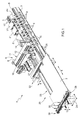
- a processing machine for panels 2 made of wood or the like comprising an elongated base 3 extending in a horizontal direction 4, which is substantially U-shaped, and has two longitudinal guiding members 5 parallel to said direction 4.
- the machine 1 also comprises a bridge crane 6, in turn comprising a vertical upright member 7, which is coupled to the base 3 in a conventional manner so as to perform, along said base 3 and driven by a conventional drive device that is not illustrated, rectilinear movements in the direction 4, and which supports a cross member 8 attached to a free end thereof and extending above the base 3 in a direction 9 horizontal and crosswise to the direction 4, and is limited laterally in said direction 4 by two faces 10, 11 arranged opposite one another.
- a bridge crane 6 in turn comprising a vertical upright member 7, which is coupled to the base 3 in a conventional manner so as to perform, along said base 3 and driven by a conventional drive device that is not illustrated, rectilinear movements in the direction 4, and which supports a cross member 8 attached to a free end thereof and extending above the base 3 in a direction 9 horizontal and crosswise to the direction 4, and is limited laterally in said direction 4 by two faces 10, 11 arranged opposite one another.
- the face 10 supports a conventional edge-trimming unit 12 connected in a conventional manner to the cross member 8 so as to move in the direction 9 and in a direction 13 that is vertical and orthogonal to the directions 4 and 9; and the face 11 supports a conventional working head 14, which is connected in a conventional manner to the cross member 8 so as to perform rectilinear movements along said cross member 8 in the direction 9, and comprises at least one tool-carrying spindle mounted in a conventional manner on the head 14 so as to move in the direction 13.
- the machine 1 is also provided with a plurality of cross elements 15, which are referred to in the following description as "working planes", extending between the longitudinal members 5 and in the direction 9, and slidingly coupled to said longitudinal members 5 so as to perform, with respect to the base 3, rectilinear movements in the direction 4.
- the working planes 15 support a plurality of supporting blocks 16, each of which is coupled in a conventional manner to the relative working plane 15 so as to perform rectilinear movements along the relative working plane 15 in the direction 9, and is upperly limited by a substantially flat and horizontal face 17 that defines, with the upper faces 17 of the other blocks 16, a substantially horizontal supporting plane P1 and is selectively connectable to a conventional pneumatic suction device that is not illustrated.
- Each block 16 supports a lifting device 18 comprising an actuating cylinder 19 fixed to the block 16 parallel to the direction 13, and a pair of supporting rollers 20 idly mounted on the free end of an output shaft 21 of the cylinder 19 so as to rotate about an axis 22 of rotation parallel to the direction 9.
- the rollers 20 are moved by the cylinder 19 between a lowered resting position ( figure 2 ) in which the rollers 20 are coplanar to or lower than the plane P1, and a raised working position ( figure 3 ), in which the rollers 20 define a supporting plane P2 parallel to and above said plane P1.
- the machine 1 also comprises a feed unit 23 suitable to feed the panels 2 above the blocks 16 and comprising, in turn, a base 24, which is aligned with the base 3 in the direction 4, and supports a roller supporting device 25 and a grip and transfer unit 26.
- the device 25 comprises a plurality of supporting bars 27 parallel to one another, which extend in the direction 4, and support relative pluralities of idle supporting rollers 28; and the unit 26 comprises a supporting bar 29, which extends in the direction 9, is mobile, with respect to the base 24, in the direction 4, and supports a plurality of gripping members 30, which are distributed along the bar 29 in the direction 9, are shaped so as to grip the panels 2 in correspondence with a rear edge thereof parallel to the direction 9, and are mobile in said direction 9 synchronously with one another during the processing of the panel 2 and independently of one another during a tooling step of the machine 1.
- both the bars 27 of the device 25, and the bar 29 of the unit 26 are mobile, with respect to the base 24, in the direction 13 between a raised position, in which the rollers 28 and the plane P2 are substantially coplanar, and a lowered position, in which the rollers 28 and the plane P1 are substantially coplanar.
- rollers 20 and 28 are eliminated and replaced, for instance, with ball bearings.
- the rollers 20, the rollers 28, and the members 30 are moved to their lowered positions to release the panel 2 onto the blocks 16, and the blocks 16 are connected to said pneumatic suction device (not illustrated) to lock the panel 2 on the plane P1.
- the working head 14 then detaches a first component 31 from the panel 2 combining the movements of the bridge crane 6 in the direction 4 with the movements of the working head 14 in the direction 9; the component 31 is locked on the plane P1; the rollers 20 not engaged by the component 31, the rollers 28, and the members 30 are then moved back into their raised positions to lift the panel 2 to the plane P2; and the work cycle described above is repeated to detach a first set of components 31 from the panel 2, said set of components 31 being aligned with one another in the direction 4, arranged at a fixed distance from one another, and then undergoing further finishing processes, e.g. edge-trimming performed by the edge-trimming unit 12 and/or milling and/or drilling performed by the working head 14.
- edge-trimming performed by the edge-trimming unit 12 and/or milling and/or drilling performed by the working head 14.
- the panel 2 is moved in the directions 4 and/or 9 so that the work cycle described above can be repeated and a second set of components 31 can be detached and finished.
- the bridge crane 6 is fixed in the direction 4, the edge-trimming unit 12 and the working head 14 are fixed in the direction 9, and the components 31 are detached from the panel 2 and undergo further processing by combining the movements of the working planes 15 and of the gripping members 30 in the direction 4 with the movements of the supporting blocks 16 and of the gripping members 30 in the direction 9.
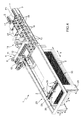
- the alternative embodiment illustrated in figure 4 only differs from that illustrated in the previous figures in that the roller supporting device 25 has been eliminated, the panels 2 are picked up from a stack 33 of panels 2, and as each panel 2 comes to the top of the stack 33 it is first moved on the stack 33 and along the plane P2 to disengage said stack 33 and then lowered from the plane P2 to the plane P1 in order to cut the components 31.
- the panels 2 are fed above the blocks 16 in the direction 9.
- the pattern of cutting the components 31 from the panel 2 can clearly differ from that described and illustrated in figures 1 and 4 .
Abstract
Description
- The present invention relates to a method for the production of panels made of wood or the like.
- In the sector of processing panels made of wood or the like, a prior art machine comprises an elongated base extending in a first given direction; a plurality of cross members mounted on the base parallel to a second direction crosswise to the first direction and mobile along the base in said first direction; a plurality of supporting blocks mounted on the cross members to define a supporting plane for at least one panel; and at least one working head for detaching a plurality of components from said panel.
- Each supporting block comprises a sliding member that is mobile along the relative cross member in the second direction, and a supporting plate mounted on the output shaft of an actuating cylinder housed inside the sliding member and suitable to move the supporting plate between a lowered position, in which the supporting plate is coplanar to the supporting plane, and a raised position, in which the supporting plate projects above said supporting plane.
- In use, each component is detached from the panel, and is then raised above the supporting plane by means of the relative supporting plates so as to undergo further finishing processes, such as drilling and/or milling and/or edge-trimming.
- The prior art machines of the type described above have some drawbacks mainly deriving from the fact that the presence of an actuating cylinder for lifting each supporting plate and the insertion thereof inside the relative sliding member makes such machines relatively complex and expensive.
- It is an object of the present invention to provide a method for the production of panels made of wood or the like that overcomes the drawbacks described above and that is simple and economical to produce.
- According to the present invention there is provided a method for the production of panels made of wood or the like as claimed in claims 1 to 10.
- The present invention also relates to a processing machine for panels made of wood or the like.
- According to the present invention there is provided a processing machine for panels made of wood or the like as claimed in
claims 11 to 23. - The present invention will now be described with reference to the accompanying drawings, illustrating a non-limiting embodiment thereof, in which:
-
figure 1 is a schematic perspective view of a preferred embodiment of the machine according to the present invention; -
figure 2 is a schematic perspective view of a detail of the machine offigure 1 illustrated in a first operating position; -
figure 3 is a schematic side view of the detail offigure 2 illustrated in a second operating position; and -
figure 4 is a schematic perspective view of an alternative embodiment of the machine offigure 1 . - With reference to
figure 1 , designated as a whole by number 1 is a processing machine forpanels 2 made of wood or the like comprising anelongated base 3 extending in ahorizontal direction 4, which is substantially U-shaped, and has two longitudinal guidingmembers 5 parallel to saiddirection 4. - The machine 1 also comprises a bridge crane 6, in turn comprising a vertical upright member 7, which is coupled to the
base 3 in a conventional manner so as to perform, along saidbase 3 and driven by a conventional drive device that is not illustrated, rectilinear movements in thedirection 4, and which supports a cross member 8 attached to a free end thereof and extending above thebase 3 in adirection 9 horizontal and crosswise to thedirection 4, and is limited laterally insaid direction 4 by twofaces - The
face 10 supports a conventional edge-trimming unit 12 connected in a conventional manner to the cross member 8 so as to move in thedirection 9 and in adirection 13 that is vertical and orthogonal to thedirections face 11 supports a conventional workinghead 14, which is connected in a conventional manner to the cross member 8 so as to perform rectilinear movements along said cross member 8 in thedirection 9, and comprises at least one tool-carrying spindle mounted in a conventional manner on thehead 14 so as to move in thedirection 13. - The machine 1 is also provided with a plurality of
cross elements 15, which are referred to in the following description as "working planes", extending between thelongitudinal members 5 and in thedirection 9, and slidingly coupled to saidlongitudinal members 5 so as to perform, with respect to thebase 3, rectilinear movements in thedirection 4. - The
working planes 15 support a plurality of supportingblocks 16, each of which is coupled in a conventional manner to therelative working plane 15 so as to perform rectilinear movements along therelative working plane 15 in thedirection 9, and is upperly limited by a substantially flat andhorizontal face 17 that defines, with theupper faces 17 of theother blocks 16, a substantially horizontal supporting plane P1 and is selectively connectable to a conventional pneumatic suction device that is not illustrated. - Each
block 16 supports alifting device 18 comprising an actuatingcylinder 19 fixed to theblock 16 parallel to thedirection 13, and a pair of supportingrollers 20 idly mounted on the free end of anoutput shaft 21 of thecylinder 19 so as to rotate about anaxis 22 of rotation parallel to thedirection 9. Therollers 20 are moved by thecylinder 19 between a lowered resting position (figure 2 ) in which therollers 20 are coplanar to or lower than the plane P1, and a raised working position (figure 3 ), in which therollers 20 define a supporting plane P2 parallel to and above said plane P1. - The machine 1 also comprises a
feed unit 23 suitable to feed thepanels 2 above theblocks 16 and comprising, in turn, abase 24, which is aligned with thebase 3 in thedirection 4, and supports aroller supporting device 25 and a grip andtransfer unit 26. - The
device 25 comprises a plurality of supportingbars 27 parallel to one another, which extend in thedirection 4, and support relative pluralities ofidle supporting rollers 28; and theunit 26 comprises a supportingbar 29, which extends in thedirection 9, is mobile, with respect to thebase 24, in thedirection 4, and supports a plurality of grippingmembers 30, which are distributed along thebar 29 in thedirection 9, are shaped so as to grip thepanels 2 in correspondence with a rear edge thereof parallel to thedirection 9, and are mobile in saiddirection 9 synchronously with one another during the processing of thepanel 2 and independently of one another during a tooling step of the machine 1. - In the specific case, both the
bars 27 of thedevice 25, and thebar 29 of theunit 26 are mobile, with respect to thebase 24, in thedirection 13 between a raised position, in which therollers 28 and the plane P2 are substantially coplanar, and a lowered position, in which therollers 28 and the plane P1 are substantially coplanar. - According to an embodiment that is not illustrated, the
rollers - The operation of the machine 1 will now be described with reference to
figures 1 ,2 and 3 and starting from a moment in which therollers 20, therollers 28 and themembers 30 are in their raised positions and in which thepanel 2 is arranged on therollers 28 and has been gripped by saidmembers 30. - After the
panel 2 has been moved by means of thebar 29 in thedirection 4 to a given position above theblocks 16, therollers 20, therollers 28, and themembers 30 are moved to their lowered positions to release thepanel 2 onto theblocks 16, and theblocks 16 are connected to said pneumatic suction device (not illustrated) to lock thepanel 2 on the plane P1. - The working
head 14 then detaches afirst component 31 from thepanel 2 combining the movements of the bridge crane 6 in thedirection 4 with the movements of the workinghead 14 in thedirection 9; thecomponent 31 is locked on the plane P1; therollers 20 not engaged by thecomponent 31, therollers 28, and themembers 30 are then moved back into their raised positions to lift thepanel 2 to the plane P2; and the work cycle described above is repeated to detach a first set ofcomponents 31 from thepanel 2, said set ofcomponents 31 being aligned with one another in thedirection 4, arranged at a fixed distance from one another, and then undergoing further finishing processes, e.g. edge-trimming performed by the edge-trimming unit 12 and/or milling and/or drilling performed by the workinghead 14. - Lastly, when the
components 31 of said first set ofcomponents 31 have been processed and unloaded from the machine 1, thepanel 2 is moved in thedirections 4 and/or 9 so that the work cycle described above can be repeated and a second set ofcomponents 31 can be detached and finished. - According to an alternative embodiment that is not illustrated, the bridge crane 6 is fixed in the
direction 4, the edge-trimming unit 12 and the workinghead 14 are fixed in thedirection 9, and thecomponents 31 are detached from thepanel 2 and undergo further processing by combining the movements of theworking planes 15 and of the grippingmembers 30 in thedirection 4 with the movements of the supportingblocks 16 and of thegripping members 30 in thedirection 9. - With regard to the above description, it should be noted that:
- the way in which the supporting
blocks 16 are arranged on the relative workingplanes 15 substantially depends on the shape and/or dimensions of thepanels 2 and of thecomponents 31; - the
panel 2 is moved to the plane P2 so that the peripheral edge of eachcomponent 31 as it is detached from saidpanel 2 is disengaged from theadjacent components 31; - by lifting the
panels 2 from the plane P1 to the plane P2,components 31 of any shape can be cut; - the
panel 2 can only be locked on the plane P1 in correspondence with eachcomponent 31 as it is detached from saidpanel 2; - in the case of
components 31 with undercuts, the plane P2 must be arranged at a distance from the plane P1 calculated as the rounded-up approximation of the thickness of thepanel 2; - the supporting
blocks 16 are selectively connected to said pneumatic suction device (not illustrated) and therollers 20 are selectively moved between the relative raised positions and the relative lowered positions according to the shape and/or dimensions of thepanels 2 and of thecomponents 31; and - the machine 1 is provided with a conventional labelling device so as to label the
panel 2 in correspondence with eachcomponent 31. - The alternative embodiment illustrated in
figure 4 only differs from that illustrated in the previous figures in that theroller supporting device 25 has been eliminated, thepanels 2 are picked up from astack 33 ofpanels 2, and as eachpanel 2 comes to the top of thestack 33 it is first moved on thestack 33 and along the plane P2 to disengage saidstack 33 and then lowered from the plane P2 to the plane P1 in order to cut thecomponents 31. - According to an alternative embodiment that is not illustrated, the
panels 2 are fed above theblocks 16 in thedirection 9. - The pattern of cutting the
components 31 from thepanel 2 can clearly differ from that described and illustrated infigures 1 and4 .
Claims (23)
- Method for the production of panels (2) made of wood or the like, comprising the following steps:arranging the panel (2) on a supporting plane (P1);locking the panel (2) on the supporting plane (P1) at least in correspondence to a component (31) to be detached from said panel (2); anddetaching the component (31) from the panel (2);and characterized in that it further comprises the following steps:keeping the component (31) locked on the supporting plane (P1);lifting the panel (2) to a transferring plane (P2) located above the supporting plane (P1); andmoving the panel (2) along the transferring plane (P2).
- Method according to claim 1, further comprising the following step:lowering the panel (2) from the transferring plane (P2) to the supporting plane (P1) before detaching the component (31) from said panel (2).
- Method according to claim 1 or 2, wherein the supporting and transferring planes (P1, P2) are substantially parallel to each other.
- Method according to one of the preceding claims, further comprising the following step:moving the panel (2) parallel to the supporting and transferring planes (P1, P2) in a first and/or second direction (4, 9), substantially orthogonal to each other
- Method according to claim 4, further comprising the following steps:successively detaching a plurality of components (31) from the panel (2);moving the panel (2) in said first and/or second direction (4, 9) to disengage a peripheral edge of each component (31) from the adjacent components (31).
- Method according to one of the preceding claims, wherein the supporting plane (P1) is defined by a plurality of supporting blocks (16), each of them being upperly limited by a respective flat face (17) connectable to a pneumatic suction device; said method further comprising the following step:selectively connecting the upper faces (17) of the supporting blocks (16) to the pneumatic suction device according to the shape and/or dimensions of the panel (2) and/or the component (31).
- Method according to one of the preceding claims, further comprising the following steps:selectively moving a plurality of lifting devices (18) of the panel (2) between relative raised working positions, wherein the lifting devices (18) are substantially coplanar to the transferring plane (P2), and relative lowered resting positions, wherein the lifting devices (18) are coplanar to, or lower than, the supporting plane (P1), according to the shape and/or the dimensions of the panel (2) and/or of the component (31).
- Method according to any one of the preceding claims, further comprising the following step:removing the panel (2) from a stack (33) of panels (2).
- Method according to one of the preceding claims, further comprising the following step:drilling and/or milling and/or edge-trimming each component (31).
- Method according to one of the preceding claims, further comprising the following step:labelling the panel (2) in correspondence to each component (31).
- Processing machine for panels (2) made of wood or the like, comprising supporting means (16) defining a substantially horizontal supporting plane (P1) for at least a panel (2); at least a working head (14) for detaching at least a component (31) from the panel (2); and locking means (16) for locking the panel (2) on the supporting plane (P1), at least in correspondence to the component (31); and characterized in that it further comprises lifting means (18, 25, 26) for moving the panel (2) from the supporting plane (P1) to a transferring plane (P2) located above the supporting plane (P1).
- Machine according to claim 11, wherein the supporting and transferring planes (P1, P2) are substantially parallel to each other.
- Machine according to claim 11 or 12, wherein the lifting means (18, 25, 26) comprise a grip and transfer unit (26) of the panel (2) mobile parallel to the supporting and transferring planes (P1, P2) in a first and/or a second direction (4, 9), substantially orthogonal to each other.
- Machine according to claim 13, wherein the grip and transfer unit (26) is mobile in a third direction (13) orthogonal to the supporting and transferring planes (P1, P2).
- Machine according to one of claims 11-14, wherein the lifting means (18, 25, 26) further comprise a plurality of lifting means (18) of the panel (2) selectively mobile between relative raised working positions, wherein the lifting devices (18) are substantially coplanar to the transferring plane (P2), and relative lowered resting positions, wherein the lifting devices (18) are coplanar to, or below the supporting plane (P1) according to the shape and/or the dimensions of the panel (2) and/or of the component (31).
- Machine according to claim 15, wherein each lifting device is provided with relative rolling means (20) of the panel (2) on the transferring plane (P2).
- Machine according to one of the claims 11-16, wherein the supporting means (16) comprise a plurality of supporting blocks (16) upperly limited by respective flat faces (17), which define the supporting plane (P1), and which are selectively connectable to a pneumatic suction device according to the shape and/or the dimensions of the panel (2) and/or the component (31).
- Machine according to claim 17 when it is dependent on claim 15, wherein each said lifting device (18) is supported by a relative said supporting block (16).
- Machine according to claim 17 or 18, wherein the supporting blocks (16) are mobile parallel to the supporting and transferring planes (P1, P2) in a first and/or a second direction (4, 9) substantially orthogonal to each other.
- Machine according to claim 19, further comprising a base (3) extending in the first direction (4); and a plurality of cross elements (15), which are mounted on the base (3), parallel to the second direction (9), are mobile along the base (3) in the first direction (4) and each of which supports at least a relative said supporting block (16) mobile along the cross element (15) in said second direction (9).
- Machine according to one of claims 11-20, wherein the working head (14) is mobile, parallel to the supporting and transferring planes (P1, P2) in a first and/or a second direction (4, 9), substantially orthogonal to each other.
- Machine according to one of claims 11-21, further comprising drilling and/or milling and/or edge-trimming means for the components (31).
- Machine according to one of claims 11-22, further comprising a labelling device (32) for labelling the panel (2) in correspondence to each component (31).
Applications Claiming Priority (1)
| Application Number | Priority Date | Filing Date | Title |
|---|---|---|---|
| ITBO2008A000515A IT1394176B1 (en) | 2008-08-07 | 2008-08-07 | METHOD AND MACHINE FOR PROCESSING WOODEN OR SIMILAR PANELS |
Publications (2)
| Publication Number | Publication Date |
|---|---|
| EP2153955A1 true EP2153955A1 (en) | 2010-02-17 |
| EP2153955B1 EP2153955B1 (en) | 2012-12-12 |
Family
ID=40578778
Family Applications (1)
| Application Number | Title | Priority Date | Filing Date |
|---|---|---|---|
| EP20090167512 Active EP2153955B1 (en) | 2008-08-07 | 2009-08-07 | Method and apparatus for the production of panels made of wood or the like. |
Country Status (2)
| Country | Link |
|---|---|
| EP (1) | EP2153955B1 (en) |
| IT (1) | IT1394176B1 (en) |
Cited By (2)
| Publication number | Priority date | Publication date | Assignee | Title |
|---|---|---|---|---|
| WO2021089074A1 (en) * | 2019-11-10 | 2021-05-14 | Martin Zimmer | Production cell with at least two machining robots |
| DE102017012078B4 (en) | 2016-12-31 | 2024-02-22 | Günther Zimmer | Movable support device with at least two support frames |
Families Citing this family (1)
| Publication number | Priority date | Publication date | Assignee | Title |
|---|---|---|---|---|
| CN103786223B (en) * | 2014-02-19 | 2015-09-30 | 海安县华达铝型材有限公司 | Use and move left and right leading screw and the method for processing sheet material of energy spraying coating material |
Citations (3)
| Publication number | Priority date | Publication date | Assignee | Title |
|---|---|---|---|---|
| DE4101904A1 (en) * | 1990-01-25 | 1991-08-08 | Heian Corp | METHOD AND DEVICE FOR PROCESSING WOOD |
| DE29616208U1 (en) * | 1996-09-18 | 1996-10-31 | Ima Maschinenfabriken Klessmann Gmbh | Machine tool with sawing device |
| EP1837143A1 (en) * | 2006-03-22 | 2007-09-26 | Bernd Butzer | Machine tool for machining boards |
-
2008
- 2008-08-07 IT ITBO2008A000515A patent/IT1394176B1/en active
-
2009
- 2009-08-07 EP EP20090167512 patent/EP2153955B1/en active Active
Patent Citations (3)
| Publication number | Priority date | Publication date | Assignee | Title |
|---|---|---|---|---|
| DE4101904A1 (en) * | 1990-01-25 | 1991-08-08 | Heian Corp | METHOD AND DEVICE FOR PROCESSING WOOD |
| DE29616208U1 (en) * | 1996-09-18 | 1996-10-31 | Ima Maschinenfabriken Klessmann Gmbh | Machine tool with sawing device |
| EP1837143A1 (en) * | 2006-03-22 | 2007-09-26 | Bernd Butzer | Machine tool for machining boards |
Cited By (2)
| Publication number | Priority date | Publication date | Assignee | Title |
|---|---|---|---|---|
| DE102017012078B4 (en) | 2016-12-31 | 2024-02-22 | Günther Zimmer | Movable support device with at least two support frames |
| WO2021089074A1 (en) * | 2019-11-10 | 2021-05-14 | Martin Zimmer | Production cell with at least two machining robots |
Also Published As
| Publication number | Publication date |
|---|---|
| ITBO20080515A1 (en) | 2010-02-08 |
| EP2153955B1 (en) | 2012-12-12 |
| IT1394176B1 (en) | 2012-06-01 |
Similar Documents
| Publication | Publication Date | Title |
|---|---|---|
| CN110814774A (en) | Full-automatic angle steel machining device and machining method | |
| CN211414313U (en) | Full-automatic angle steel processingequipment | |
| JP2020037176A (en) | Post-processing device of raised floor | |
| KR101537757B1 (en) | Piercing system | |
| CN103056532A (en) | Laser cutter standalone automatic feeding and discharging device and laser cutter standalone automatic feeding and discharging method | |
| CN210549494U (en) | Plate shearing and punching integrated production line | |
| WO2017049564A1 (en) | Cyclic double-deck conveying device | |
| CN108925047B (en) | Full-automatic pin punching and encapsulation production line for PCB (printed circuit board) | |
| JP2012513900A (en) | Tube chamfering equipment | |
| CN108454075A (en) | Double courages press suction molding machine parallel | |
| ITTV20090189A1 (en) | MACHINE FOR PROCESSING MATERIAL IN SHEETS, IN PARTICULAR OF NATURAL AND AGGLOMERATE STONE MATERIAL, CERAMIC MATERIAL, GLASS MATERIAL. | |
| CN106271650B (en) | One kind is used for vehicle dormer window guide rail automatic press former | |
| JP2009208080A (en) | Workpiece conveying device | |
| EP2153955B1 (en) | Method and apparatus for the production of panels made of wood or the like. | |
| KR101929576B1 (en) | Groove machining equipment | |
| CN201276325Y (en) | Conveyer | |
| CN210126926U (en) | Stacker crane for laser cutting equipment | |
| CN107310911A (en) | A kind of control method for overturning and carrying workpiece | |
| CN206088345U (en) | Machine -building grabbing device | |
| CN116690664A (en) | Full-automatic cutting equipment and method for intelligent positioning of graphene electric heating plates | |
| CN212765431U (en) | Plate engraving machine | |
| KR20130101181A (en) | Pressed material supply method and apparatus | |
| CN214109509U (en) | Production equipment for steel bar truss floor bearing plate | |
| CN211640532U (en) | Intelligent stone cutting machine with double working platforms and walking beams | |
| JP4476648B2 (en) | Multi-step single press method and press apparatus |
Legal Events
| Date | Code | Title | Description |
|---|---|---|---|
| PUAI | Public reference made under article 153(3) epc to a published international application that has entered the european phase |
Free format text: ORIGINAL CODE: 0009012 |
|
| AK | Designated contracting states |
Kind code of ref document: A1 Designated state(s): AT BE BG CH CY CZ DE DK EE ES FI FR GB GR HR HU IE IS IT LI LT LU LV MC MK MT NL NO PL PT RO SE SI SK SM TR |
|
| 17P | Request for examination filed |
Effective date: 20100816 |
|
| 17Q | First examination report despatched |
Effective date: 20100920 |
|
| GRAP | Despatch of communication of intention to grant a patent |
Free format text: ORIGINAL CODE: EPIDOSNIGR1 |
|
| GRAS | Grant fee paid |
Free format text: ORIGINAL CODE: EPIDOSNIGR3 |
|
| GRAA | (expected) grant |
Free format text: ORIGINAL CODE: 0009210 |
|
| AK | Designated contracting states |
Kind code of ref document: B1 Designated state(s): AT BE BG CH CY CZ DE DK EE ES FI FR GB GR HR HU IE IS IT LI LT LU LV MC MK MT NL NO PL PT RO SE SI SK SM TR |
|
| REG | Reference to a national code |
Ref country code: GB Ref legal event code: FG4D |
|
| REG | Reference to a national code |
Ref country code: CH Ref legal event code: EP |
|
| REG | Reference to a national code |
Ref country code: AT Ref legal event code: REF Ref document number: 588107 Country of ref document: AT Kind code of ref document: T Effective date: 20121215 |
|
| REG | Reference to a national code |
Ref country code: IE Ref legal event code: FG4D |
|
| REG | Reference to a national code |
Ref country code: DE Ref legal event code: R096 Ref document number: 602009011862 Country of ref document: DE Effective date: 20130207 |
|
| PG25 | Lapsed in a contracting state [announced via postgrant information from national office to epo] |
Ref country code: FI Free format text: LAPSE BECAUSE OF FAILURE TO SUBMIT A TRANSLATION OF THE DESCRIPTION OR TO PAY THE FEE WITHIN THE PRESCRIBED TIME-LIMIT Effective date: 20121212 Ref country code: ES Free format text: LAPSE BECAUSE OF FAILURE TO SUBMIT A TRANSLATION OF THE DESCRIPTION OR TO PAY THE FEE WITHIN THE PRESCRIBED TIME-LIMIT Effective date: 20130323 Ref country code: LT Free format text: LAPSE BECAUSE OF FAILURE TO SUBMIT A TRANSLATION OF THE DESCRIPTION OR TO PAY THE FEE WITHIN THE PRESCRIBED TIME-LIMIT Effective date: 20121212 Ref country code: SE Free format text: LAPSE BECAUSE OF FAILURE TO SUBMIT A TRANSLATION OF THE DESCRIPTION OR TO PAY THE FEE WITHIN THE PRESCRIBED TIME-LIMIT Effective date: 20121212 Ref country code: NO Free format text: LAPSE BECAUSE OF FAILURE TO SUBMIT A TRANSLATION OF THE DESCRIPTION OR TO PAY THE FEE WITHIN THE PRESCRIBED TIME-LIMIT Effective date: 20130312 |
|
| REG | Reference to a national code |
Ref country code: NL Ref legal event code: VDEP Effective date: 20121212 |
|
| REG | Reference to a national code |
Ref country code: AT Ref legal event code: MK05 Ref document number: 588107 Country of ref document: AT Kind code of ref document: T Effective date: 20121212 |
|
| REG | Reference to a national code |
Ref country code: LT Ref legal event code: MG4D |
|
| PG25 | Lapsed in a contracting state [announced via postgrant information from national office to epo] |
Ref country code: GR Free format text: LAPSE BECAUSE OF FAILURE TO SUBMIT A TRANSLATION OF THE DESCRIPTION OR TO PAY THE FEE WITHIN THE PRESCRIBED TIME-LIMIT Effective date: 20130313 Ref country code: LV Free format text: LAPSE BECAUSE OF FAILURE TO SUBMIT A TRANSLATION OF THE DESCRIPTION OR TO PAY THE FEE WITHIN THE PRESCRIBED TIME-LIMIT Effective date: 20121212 Ref country code: SI Free format text: LAPSE BECAUSE OF FAILURE TO SUBMIT A TRANSLATION OF THE DESCRIPTION OR TO PAY THE FEE WITHIN THE PRESCRIBED TIME-LIMIT Effective date: 20121212 |
|
| PG25 | Lapsed in a contracting state [announced via postgrant information from national office to epo] |
Ref country code: CZ Free format text: LAPSE BECAUSE OF FAILURE TO SUBMIT A TRANSLATION OF THE DESCRIPTION OR TO PAY THE FEE WITHIN THE PRESCRIBED TIME-LIMIT Effective date: 20121212 Ref country code: BG Free format text: LAPSE BECAUSE OF FAILURE TO SUBMIT A TRANSLATION OF THE DESCRIPTION OR TO PAY THE FEE WITHIN THE PRESCRIBED TIME-LIMIT Effective date: 20130312 Ref country code: EE Free format text: LAPSE BECAUSE OF FAILURE TO SUBMIT A TRANSLATION OF THE DESCRIPTION OR TO PAY THE FEE WITHIN THE PRESCRIBED TIME-LIMIT Effective date: 20121212 Ref country code: IS Free format text: LAPSE BECAUSE OF FAILURE TO SUBMIT A TRANSLATION OF THE DESCRIPTION OR TO PAY THE FEE WITHIN THE PRESCRIBED TIME-LIMIT Effective date: 20130412 Ref country code: AT Free format text: LAPSE BECAUSE OF FAILURE TO SUBMIT A TRANSLATION OF THE DESCRIPTION OR TO PAY THE FEE WITHIN THE PRESCRIBED TIME-LIMIT Effective date: 20121212 Ref country code: SK Free format text: LAPSE BECAUSE OF FAILURE TO SUBMIT A TRANSLATION OF THE DESCRIPTION OR TO PAY THE FEE WITHIN THE PRESCRIBED TIME-LIMIT Effective date: 20121212 Ref country code: BE Free format text: LAPSE BECAUSE OF FAILURE TO SUBMIT A TRANSLATION OF THE DESCRIPTION OR TO PAY THE FEE WITHIN THE PRESCRIBED TIME-LIMIT Effective date: 20121212 |
|
| PG25 | Lapsed in a contracting state [announced via postgrant information from national office to epo] |
Ref country code: RO Free format text: LAPSE BECAUSE OF FAILURE TO SUBMIT A TRANSLATION OF THE DESCRIPTION OR TO PAY THE FEE WITHIN THE PRESCRIBED TIME-LIMIT Effective date: 20121212 Ref country code: PT Free format text: LAPSE BECAUSE OF FAILURE TO SUBMIT A TRANSLATION OF THE DESCRIPTION OR TO PAY THE FEE WITHIN THE PRESCRIBED TIME-LIMIT Effective date: 20130412 Ref country code: NL Free format text: LAPSE BECAUSE OF FAILURE TO SUBMIT A TRANSLATION OF THE DESCRIPTION OR TO PAY THE FEE WITHIN THE PRESCRIBED TIME-LIMIT Effective date: 20121212 Ref country code: PL Free format text: LAPSE BECAUSE OF FAILURE TO SUBMIT A TRANSLATION OF THE DESCRIPTION OR TO PAY THE FEE WITHIN THE PRESCRIBED TIME-LIMIT Effective date: 20121212 |
|
| PLBE | No opposition filed within time limit |
Free format text: ORIGINAL CODE: 0009261 |
|
| STAA | Information on the status of an ep patent application or granted ep patent |
Free format text: STATUS: NO OPPOSITION FILED WITHIN TIME LIMIT |
|
| PG25 | Lapsed in a contracting state [announced via postgrant information from national office to epo] |
Ref country code: DK Free format text: LAPSE BECAUSE OF FAILURE TO SUBMIT A TRANSLATION OF THE DESCRIPTION OR TO PAY THE FEE WITHIN THE PRESCRIBED TIME-LIMIT Effective date: 20121212 |
|
| 26N | No opposition filed |
Effective date: 20130913 |
|
| PG25 | Lapsed in a contracting state [announced via postgrant information from national office to epo] |
Ref country code: CY Free format text: LAPSE BECAUSE OF FAILURE TO SUBMIT A TRANSLATION OF THE DESCRIPTION OR TO PAY THE FEE WITHIN THE PRESCRIBED TIME-LIMIT Effective date: 20121212 Ref country code: HR Free format text: LAPSE BECAUSE OF FAILURE TO SUBMIT A TRANSLATION OF THE DESCRIPTION OR TO PAY THE FEE WITHIN THE PRESCRIBED TIME-LIMIT Effective date: 20121212 |
|
| REG | Reference to a national code |
Ref country code: DE Ref legal event code: R097 Ref document number: 602009011862 Country of ref document: DE Effective date: 20130913 |
|
| REG | Reference to a national code |
Ref country code: CH Ref legal event code: PL |
|
| GBPC | Gb: european patent ceased through non-payment of renewal fee |
Effective date: 20130807 |
|
| PG25 | Lapsed in a contracting state [announced via postgrant information from national office to epo] |
Ref country code: CH Free format text: LAPSE BECAUSE OF NON-PAYMENT OF DUE FEES Effective date: 20130831 Ref country code: MC Free format text: LAPSE BECAUSE OF FAILURE TO SUBMIT A TRANSLATION OF THE DESCRIPTION OR TO PAY THE FEE WITHIN THE PRESCRIBED TIME-LIMIT Effective date: 20121212 Ref country code: LI Free format text: LAPSE BECAUSE OF NON-PAYMENT OF DUE FEES Effective date: 20130831 |
|
| REG | Reference to a national code |
Ref country code: IE Ref legal event code: MM4A |
|
| REG | Reference to a national code |
Ref country code: FR Ref legal event code: ST Effective date: 20140430 |
|
| PG25 | Lapsed in a contracting state [announced via postgrant information from national office to epo] |
Ref country code: GB Free format text: LAPSE BECAUSE OF NON-PAYMENT OF DUE FEES Effective date: 20130807 Ref country code: IE Free format text: LAPSE BECAUSE OF NON-PAYMENT OF DUE FEES Effective date: 20130807 |
|
| PG25 | Lapsed in a contracting state [announced via postgrant information from national office to epo] |
Ref country code: FR Free format text: LAPSE BECAUSE OF NON-PAYMENT OF DUE FEES Effective date: 20130902 |
|
| PG25 | Lapsed in a contracting state [announced via postgrant information from national office to epo] |
Ref country code: SM Free format text: LAPSE BECAUSE OF FAILURE TO SUBMIT A TRANSLATION OF THE DESCRIPTION OR TO PAY THE FEE WITHIN THE PRESCRIBED TIME-LIMIT Effective date: 20121212 |
|
| PG25 | Lapsed in a contracting state [announced via postgrant information from national office to epo] |
Ref country code: TR Free format text: LAPSE BECAUSE OF FAILURE TO SUBMIT A TRANSLATION OF THE DESCRIPTION OR TO PAY THE FEE WITHIN THE PRESCRIBED TIME-LIMIT Effective date: 20121212 Ref country code: MT Free format text: LAPSE BECAUSE OF FAILURE TO SUBMIT A TRANSLATION OF THE DESCRIPTION OR TO PAY THE FEE WITHIN THE PRESCRIBED TIME-LIMIT Effective date: 20121212 |
|
| PG25 | Lapsed in a contracting state [announced via postgrant information from national office to epo] |
Ref country code: HU Free format text: LAPSE BECAUSE OF FAILURE TO SUBMIT A TRANSLATION OF THE DESCRIPTION OR TO PAY THE FEE WITHIN THE PRESCRIBED TIME-LIMIT; INVALID AB INITIO Effective date: 20090807 Ref country code: LU Free format text: LAPSE BECAUSE OF NON-PAYMENT OF DUE FEES Effective date: 20130807 Ref country code: MK Free format text: LAPSE BECAUSE OF FAILURE TO SUBMIT A TRANSLATION OF THE DESCRIPTION OR TO PAY THE FEE WITHIN THE PRESCRIBED TIME-LIMIT Effective date: 20121212 |
|
| PGFP | Annual fee paid to national office [announced via postgrant information from national office to epo] |
Ref country code: IT Payment date: 20230718 Year of fee payment: 15 |
|
| PGFP | Annual fee paid to national office [announced via postgrant information from national office to epo] |
Ref country code: DE Payment date: 20230828 Year of fee payment: 15 |