EP2153917A2 - Spreader tool for pipes and pipe press coupling - Google Patents
Spreader tool for pipes and pipe press coupling Download PDFInfo
- Publication number
- EP2153917A2 EP2153917A2 EP09010375A EP09010375A EP2153917A2 EP 2153917 A2 EP2153917 A2 EP 2153917A2 EP 09010375 A EP09010375 A EP 09010375A EP 09010375 A EP09010375 A EP 09010375A EP 2153917 A2 EP2153917 A2 EP 2153917A2
- Authority
- EP
- European Patent Office
- Prior art keywords
- expansion
- pipe
- tool
- tube
- tool according
- Prior art date
- Legal status (The legal status is an assumption and is not a legal conclusion. Google has not performed a legal analysis and makes no representation as to the accuracy of the status listed.)
- Withdrawn
Links
Images


Classifications
-
- B—PERFORMING OPERATIONS; TRANSPORTING
- B21—MECHANICAL METAL-WORKING WITHOUT ESSENTIALLY REMOVING MATERIAL; PUNCHING METAL
- B21D—WORKING OR PROCESSING OF SHEET METAL OR METAL TUBES, RODS OR PROFILES WITHOUT ESSENTIALLY REMOVING MATERIAL; PUNCHING METAL
- B21D41/00—Application of procedures in order to alter the diameter of tube ends
- B21D41/02—Enlarging
- B21D41/026—Enlarging by means of mandrels
-
- B—PERFORMING OPERATIONS; TRANSPORTING
- B21—MECHANICAL METAL-WORKING WITHOUT ESSENTIALLY REMOVING MATERIAL; PUNCHING METAL
- B21D—WORKING OR PROCESSING OF SHEET METAL OR METAL TUBES, RODS OR PROFILES WITHOUT ESSENTIALLY REMOVING MATERIAL; PUNCHING METAL
- B21D39/00—Application of procedures in order to connect objects or parts, e.g. coating with sheet metal otherwise than by plating; Tube expanders
- B21D39/08—Tube expanders
- B21D39/20—Tube expanders with mandrels, e.g. expandable
-
- F—MECHANICAL ENGINEERING; LIGHTING; HEATING; WEAPONS; BLASTING
- F16—ENGINEERING ELEMENTS AND UNITS; GENERAL MEASURES FOR PRODUCING AND MAINTAINING EFFECTIVE FUNCTIONING OF MACHINES OR INSTALLATIONS; THERMAL INSULATION IN GENERAL
- F16L—PIPES; JOINTS OR FITTINGS FOR PIPES; SUPPORTS FOR PIPES, CABLES OR PROTECTIVE TUBING; MEANS FOR THERMAL INSULATION IN GENERAL
- F16L13/00—Non-disconnectible pipe-joints, e.g. soldered, adhesive or caulked joints
- F16L13/14—Non-disconnectible pipe-joints, e.g. soldered, adhesive or caulked joints made by plastically deforming the material of the pipe, e.g. by flanging, rolling
- F16L13/147—Non-disconnectible pipe-joints, e.g. soldered, adhesive or caulked joints made by plastically deforming the material of the pipe, e.g. by flanging, rolling by radially expanding the inner part
Definitions
- the invention relates to a widening tool for expanding the end of a tube, which tool has a housing and an actuatable by an actuating device Aufweit emotions.
- the invention further relates to a use of the tool and a method for expanding the end of a multilayer composite pipe or thin-walled metal pipe.
- the invention relates to a pipe compression coupling and a method for forming a pipe press connection.
- multilayer composite pipes consist of metallic and non-metallic layers that are bonded together by adhesive and adhesion promoter.
- the advantage of multi-layer composite pipes is the reduction of the required cost-intensive metal quantities and good processing properties (eg easy bendability) without losing the advantages of metallic pipes.
- an intermediate layer made of aluminum is coated on the outside and on the inside with a plastic layer.
- multi-layer composite pipes with a thin copper layer inside as well as an external plastic sheath developed. Especially with the latter tube types, however, the use of press-fit couplings encounters certain problems.
- pipe-type couplings of the outer-sealing type which do not require a plug-in sleeve inserted into the pipe end, as well as internally-sealed pipe-type couplings in which a support sleeve is required.
- pipe-type couplings of the outer-sealing type which do not require a plug-in sleeve inserted into the pipe end
- internally-sealed pipe-type couplings in which a support sleeve is required.
- For compression of multi-layer composite pipes - at least for small pipe cross sections, as are common in the installation technology - experience has shown that due to the less favorable compression properties only inner sealing pipe couplings using a support sleeve used. Since the support sleeves come into contact with the medium conducted in the pipelines, they are to be manufactured from a material which is electrochemically comparable to copper, generally brass.
- EP-A-1 674 241 is proposed to remedy this disadvantage, a smoothing sleeve, which is arranged between the Aufweit emotions the expansion tool and the inside of the tube. This can be a non-uniform deformation can be reduced by the individual expansion segments, a tearing of the metal layer is still possible.
- the invention is based on the object to provide an improved expansion tool, which is particularly suitable for multilayer composite pipes and thin-walled metal pipes.
- the object is achieved in a widening tool of the type mentioned above in that the tool has a tool housing on the housing, the Aufweitigen having a predetermined distance surrounding limiting sleeve, which is a substantially hollow cylindrical Provides expansion limit for the pipe to be expanded.
- the hollow cylindrical limiting sleeve of the tool provides a limit to the expansion by the tool whose inner diameter corresponds to the desired by the expansion outer diameter of the pipe end, damage to the pipe can be prevented during expansion.
- this constraining sleeve tends to prevent excessive deformations caused by discrete segments of the expander tool, possibly due to inhomogeneities of the metal layer (e.g., at its weld), as the sleeve serves as a limit to the expansion process.
- any ovality and dimensional inaccuracies of the tube such as may occur e.g. produced during cutting or due to manufacturing tolerances, eliminated, so that an otherwise required processing of the pipe end can be omitted.
- the inner diameter of the limiting sleeve of the tool is selected so that damage to the expansion through the boundary is avoided as safely as possible for a given type of pipe.
- the expansion is selected as large as possible within this limit so that the wall thickness of the support sleeve of the pipe press connection is largely or completely compensated.
- the limiting sleeve is replaceably attached to the tool, in particular by means of a screw thread. This allows easy replacement, and it is particularly preferred if the limiting sleeve also serves to hold the Aufweit emotionss, so that with removal of the limiting sleeve and the Aufweitigen is accessible for replacement.
- the expansion body is a radially elastically extensible body, which is expanded by fluid pressure. This gives a particularly even expansion and thereby further reduces the risk of damage to a composite pipe on. Also impressions or marks in the tube are reliably prevented by the expansion tool.
- the elastic expansion body which is formed in particular from an elastomer, is eg expanded pneumatically or hydraulically, wherein the actuating arrangement can build up the fluid pressure or the pneumatic or hydraulic pressure manually or by motor or can have a prefilled, replaceable compressed air reservoir.
- the elastic expansion body is designed such that its expansion takes place substantially radially. This can be supported by the expansion body is provided on the inside tube side with a fastening means to which a holder is fastened, which prevents the expansion in the longitudinal direction.
- this holder is formed by the pressure introduction line in the Aufweit emotions.
- an expansion body consisting of a plurality of expansion body parts, the expansion body parts of which can be moved apart radially by the actuating arrangement.
- an expansion body is used which has only three or four Aufweit emotionsmaschine. This results in a larger adjacent surface of Aufweit stressess on the tube inside during expansion.
- the invention is further based on the object to provide an improved pipe press connection.
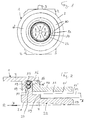
- FIG. 1 shows a frontal view of the tool from the front or a view in the direction of arrow A of Figure 2.
- Figure 2 shows a vertical sectional view through a part of the tool, wherein only the parts above the longitudinal center axis R are shown, since the tool is constructed with respect to the relevant to the invention elements of the tool substantially rotationally symmetrical about this axis R.
- the Aufweitmaschine 22 can be seen, which is constructed in a known per se of several Aufweitmaschineska 4-9. This Aufweit stresses 22 is arranged in a tool housing 2, which is only indicated in the figures and is formed in the skilled person for these tools known manner, unless otherwise described below.
- the tool may be a hand-operated tool or possibly a pneumatically or electrically actuated widening tool.
- an actuating means is indicated only with the lever portion 3 and in the FIGS. 6 and 8 with the mandrel 30, the main actuating means for spreading the Aufweit emotionss indicated, which will be explained.
- the parts 4-9 of the expander substantially to each other and form an expander 22 with a defined circumference.
- the Aufweitpian is usually of cylindrical shape. In this insertion position, the dilated end of the tube 12 can be pushed onto the Aufweitmaschine 22, wherein the Aufschiebeine may be limited by a stop 19 of Aufweit emotionss.
- the individual parts 4-9 of Aufweit emotionss be held together, for example by an elastic member 14, which may be an O-ring made of rubber, for example.
- the expansion body 22 thus formed is held and guided in the housing 2 of the expansion tool 1, wherein in the example shown this takes place by an annular groove 13 which is formed by a web 17 and a stop 18. In this groove, a web 28 of Aufweit emotionss 22 is received, which is formed on the individual parts 4 to 9.
- the expansion body further has an inner opening 20, the wall 21 of which extends conically towards the end face 23 of the expansion body 22. This allows the expansion movement by the insertion of a conical mandrel into the cavity 20, which presses the individual parts of the Aufweit emotionss radially outward, which is known. This expansion is in the FIGS.
- the expanding tool described so far substantially corresponds to the prior art and has the disadvantage that sensitive pipes and in particular multi-layer composite pipes are damaged during the expansion can be. That in the FIGS. 1 and 3 shown multilayer composite pipe 12 has a metal layer and an inner and outer plastic layer.
- the expansion tool 1 according to the invention now additionally has a limiting sleeve 10 which, with its inner side 10 ', forms a bearing for the widened pipe end and limits the widening to the permissible extent.
- an annular cavity 11 is provided between the inner wall 10 'of the limiting sleeve 10 and the tube outer side 12'.
- the radial extent between the outer side 12 'of the tube and the inner side 10' of the limiting sleeve corresponds to half of the maximum possible expansion.
- FIGS. 3 and 4 Accordingly, it is shown that the expansion of the tube end of the tube 12 has taken place until the tube 12 bears against the inner side 10 'of the limiting sleeve.
- the expansion is limited and terminated and damage to the pipe end can be safely avoided.
- the limiting sleeve is releasably attached to the tool 1, for which purpose, for example, an external thread 16 may be provided on a shoulder 10 "of the sleeve 10, which cooperates with a corresponding internal thread on the housing 2 in order to screw the sleeve to the housing can. Further, it is preferred if the sleeve 10 at the same time forms a boundary of the receiving groove 13 for the expander 22.
- the expander can be easily removed from the tool by removing the detachable sleeve 10 and optionally replaced by a differently dimensioned expander
- a simple adaptation to the pipe diameter and the type of pipe, in particular its multilayer structure can thus be achieved.
- the Figures 5-8 show a further embodiment of Aufweit emotionss 22, which instead of in the Figures 1-4 shown
- Aufweit emotionss can be used in the expansion tool 1.
- the same reference numerals designate again the same elements.
- the expansion body 22 in this example consists of only four parts 24 to 27 instead of six parts. This is preferred in order to achieve the largest possible surface of the expander body resting against the pipe or to keep the number of intermediate spaces between the expander body parts 24-27 as small as possible. This promotes the uniform expansion of the tube. Also, a variant not shown with three Aufweit emotions sculpture is advantageous. In the FIGS.
- a mandrel 30 is indicated, which in a known manner by advancing in the direction B ( Figures 2 and 4 ) expands the Aufweitmaschinemaschine 24-27, starting from the insertion position to the maximum Aufweitposition.
- the maximum widening position is in turn defined by the limiting sleeve 10.
- FIG. 9 shows a further embodiment similar to that of Figures 5-8 , wherein here on the shoulder 29, a further elastically deformable retaining means 31 is arranged, which holds the expansion body 22 in addition to the element 14.
- the element 31 may be a spring or may in turn be a rubber-elastic element. Its position on the shoulder 29 can be fixed by a circumferential nose 32.
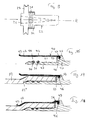
- FIGS. 10 to 12 show a first example and the FIGS. 13 to 15 a further example of a preferred embodiment in which the Aufweit stresses 22 'from a dimensionally stable but elastically deformable plastic material or rubber material (an elastomer) is formed, which deforms elastically under force and when the force is lost in the original undeformed figure returns.
- the expansion body is formed in the form of a body having at rest substantially the shape of a cylinder with an internal cavity, which allows a radial expansion of the cylinder by introducing a fluid under pressure.
- the expander can expand the pipe end of the tube 12 and press against the limiting sleeve 10, as has been explained in principle for the previous embodiments.
- FIGS. 10 and 11 show a part of such expansion tool 1, once in the insertion position, in which the end of the tube is pushed over the expansion body 22 '( FIG. 10 ) and once in the Aufweit ein in which the pipe end has been widened ( FIG. 11 ).
- the expander 22 'of this embodiment is in FIG. 12 shown alone.
- like reference numerals as used in the previous figures denote identical or functionally identical parts; also for these embodiments, the essential parts are rotationally symmetrical to the longitudinal central axis and therefore the sectional drawings are executed in part only above this longitudinal central axis.
- the expansion tool in turn has only a partially shown housing 2 and the limiting sleeve 10.
- This may be integral with the housing or be releasably secured thereto, as indicated by the thread 16 in the housing and on the sleeve 10.
- the expander 22 is fastened in the tool housing by means of a flange 68 provided on the latter at the end thereof on the actuation side, by releasably fixing this flange (which may be annular in a continuous or intermittent manner) in the housing.
- a screw 17 ' is provided in the example.
- the expansion body has in this example apart from the flange 68 and the front, tube-side end 62 along the intermediate section 61 substantially the same wall thickness, which results in the undeformed state of rest uniformly cylindrical cavity 60.
- At the front end 62 of the Aufweitpian is provided with a greater wall thickness, since there should be no expansion.
- the fluid for widening the expansion body 22 ' is introduced into the cavity 60 via a fluid line 70 having fluid passages 71.
- the line is preferably closed.
- the line 70 is fixed in the housing, for example screwed to this, which is indicated by the thread 76.
- This attachment is carried out fluid-tight, so that the introduced under pressure by means of the line fluid remains in the cavity 60 and the expander 22 'radially expands.
- FIG. 11 shown, in which the fluid has caused the expansion of the Aufweit stresses 22 'and thus the tube 12.
- the elastomeric expander 22 'returns from the expanded position of FIG FIG. 11 back to the position of FIG. 10 back, so that the expanded tube can be removed from the cavity 11.
- the expansion has been limited by the limiting sleeve 10 in the manner already described above, whereby the advantages mentioned there have been achieved.
- air or oil is used as the fluid, which is pressurized by a hand pump of the expansion tool or a motorized pump and fed to the line 70.
- the tool can also have a compressed air connection, from which air can be obtained under the required pressure.
- you can also use air or another gas under pressure filled stock capsules are used, which can be used or applied in or on the expansion tool and then connected to the line 70.
- a hand-operated valve is preferably provided, through which the supply of fluid under pressure into the conduit 70 takes place and the discharge of the fluid from the line into the environment in the case of air or in the oil tank after the widening.
- Such valves and their connection to a fluid source and to the line 70 are known in the art and need not be explained in detail here.
- the widening actuator assembly 75 is therefore in FIG FIG. 10 only indicated as a block, which includes such a valve and possibly also the fluid source and is in communication with the line 70 of the actuator assembly.
- the housing has an annular and conical surface 69, which limits the expansion in the rear, operating side area before the actual expansion area for the tube, in which Tarberg Geb then the tube and the Aufweit emotions are arranged together.
- the surface 69 is provided between the attachment of the Aufweit emotionss on the tool and an arranged in the housing stop 67 for the pipe end.
- the Aufweitpian is preferably made in one piece from a commercially available elastomer. It may also have reinforcements of another material which do not hinder radial expansion, but prevent or reduce longitudinal stretching.
- FIGS. 13 to 15 show a further embodiment of the elastomeric Aufweit emotionss 22 'and the conduit 70, for which the above statements on the expander, where applicable, also apply.
- the remaining parts of this embodiment can be designed the same as the Aufweitwerkmaschine the Figures 10 and 11 and are therefore not shown.
- the expander 22 'of FIGS. 13 and 14 is shown at rest. It can be seen that, on the one hand, the wall thickness of the expansion body in the expansion area is not uniform, but has a region 61 'in which the wall thickness is reduced in order to facilitate the widening. In combination with it or with an expansion body according to FIG.
- a fastening means 63 is further provided inside the tube-side end of the Aufweit emotionss through which this end is fixed in the longitudinal direction, when the fastener 63 is fixed in the longitudinal direction a rigid holder.
- This is formed in particular by the line 70 itself, which is usually made of metal and therefore is to be regarded as rigid in the forces acting here.
- the conduit 70 has at its closed tube-side end a threaded portion 74 which engages in a corresponding threaded portion of the fastener 63.
- This is here a sleeve 63, for example made of metal or plastic, which is fastened in Aufweit emotions 22 '. At most, this can also form a fastener itself, which can be brought into engagement with the holder or line 70.
- the design with elastomeric Textweit emotions supports the composite tube during expansion evenly and completely and thus reduces the risk of cracking of the metallic layer even further, which is already largely avoided by the limiting sleeve.
- the elastomeric Textweit réelle analyses further prevents the formation of imprints or marks in the pipe during expansion.
- the elastomeric TextweitIER can also be produced inexpensively for different pipe sizes.
- FIGS. 16 to 18 show an embodiment of the inventive tube press coupling or Pipe press connection, whereby a coupling or a pipe press connection for any fittings is called. It may be, for example, couplings, reducers, branch pieces such as tees and crossings or connectors to fixtures, which are provided with this pipe press fitting. These have in common that they each have a support sleeve 41 which is provided for insertion into the expanded tube 12. This support sleeve, which in turn is rotationally symmetrical about its central longitudinal axis, what it in the FIGS. 16 to 18 allows to represent only the part located above the central longitudinal axis, has a sleeve part 43, which is designed for introduction into the flared pipe end of the tube 12.
- the support sleeve part 43 on its side facing the widened pipe inside surface at least one sealant, in particular in the form of O-rings 50, 51, and preferably gears 53 for engagement in the pipe surface in the finished pressed pipe press connection.
- the pipe press connection is now further provided with a ferrule 40, which is also rotationally symmetrical and substantially hollow cylindrical. This crimping sleeve 40 is preassembled attached to the support sleeve 41, so that support sleeve and ferrule form a no longer separable unit except by destruction of these parts or their attachment to each other.
- the attachment takes place in that the support sleeve 40 has an angled circumferential nose or a flange 47, which engages in a circumferential groove 46 of the support sleeve 41.
- the ferrule 40 which consists for example of sheet metal, is thereby correspondingly deformed in the production of the pipe press fitting, that it engages in the groove 46 and is no longer removably fixed to the support sleeve.
- the ferrule 40 forms with the support sleeve part 43 overlapping the crimping sleeve part 42 a cavity 44 which is dimensioned to receive the flared end of the tube 12.
- the expansion by the expansion tool which is preferably the expansion tool described above, must therefore be adapted to the pipe press connection and vice versa.
- the ferrule 40 extends beyond the support sleeve part 43 with its end facing away from the stop and holding part 45 of the support sleeve end 48, 49. Thus, it extends over the region 12 '' of the tube, in which this extends from its expanded diameter back to the normal diameter.
- FIG. 17 shows how the expanded tube is pushed onto the support sleeve 41 and in particular the support sleeve part 43. The tube comes so to lie between the support sleeve and ferrule.
Abstract
Description
Die Erfindung betrifft ein Aufweitwerkzeug zum Aufweiten des Endes eines Rohres, welches Werkzeug ein Gehäuse und einen durch eine Betätigungsanordnung betätigbaren Aufweitkörper aufweist. Die Erfindung betrifft ferner eine Verwendung des Werkzeugs sowie ein Verfahren zum Aufweiten des Endes eines Mehrschichtverbundrohres oder dünnwandigen Metallrohres.The invention relates to a widening tool for expanding the end of a tube, which tool has a housing and an actuatable by an actuating device Aufweitkörper. The invention further relates to a use of the tool and a method for expanding the end of a multilayer composite pipe or thin-walled metal pipe.
Weiter betrifft die Erfindung eine Rohrpresskupplung sowie ein Verfahren zur Bildung einer Rohrpressverbindung.Furthermore, the invention relates to a pipe compression coupling and a method for forming a pipe press connection.
Besonders im Bereich haustechnischer Installationen haben sich in den vergangenen Jahren Verpressungen zum Standardverbindungsverfahren für Rohrleitungen entwickelt. Ferner ist ein zunehmender Einsatz von Mehrschichtverbundrohren zu beobachten. Diese Rohre bestehen aus metallischen und nichtmetallischen Schichten, die durch Kleber sowie Haftvermittler miteinander verbunden sind. Der Vorteil von Mehrschichtverbundrohren besteht in der Reduktion der benötigten kostenintensiven Metallmengen und guter Verarbeitungseigenschaften (z.B. leichter Biegbarkeit), ohne dass bei ihnen die Vorteile metallischer Rohre verlorengehen. Bei einem verbreiteten Typ von Mehrschichtverbundrohren ist eine aus Aluminium bestehende Zwischenschicht aussen und innen mit einer Kunststoffschicht überzogen. Als Ersatz für massive Kupferrohre, die für Trinkwasserleitungen hinsichtlich der lebensmittelchemischen Eigenschaften in der Fachwelt nach wie vor als optimal angesehen werden, wurden Mehrschichtverbundrohre mit einer dünnen Kupferschicht im Inneren sowie einer aussen liegenden Kunststoffummantelung entwickelt. Gerade bei letzteren Rohrtypen stösst jedoch der Einsatz von Presskupplungen auf gewisse Probleme.Particularly in the field of building services installations, pressings have become the standard connection method for pipelines in recent years. Furthermore, an increasing use of multilayer composite pipes can be observed. These tubes consist of metallic and non-metallic layers that are bonded together by adhesive and adhesion promoter. The advantage of multi-layer composite pipes is the reduction of the required cost-intensive metal quantities and good processing properties (eg easy bendability) without losing the advantages of metallic pipes. In a common type of multi-layer composite pipes, an intermediate layer made of aluminum is coated on the outside and on the inside with a plastic layer. As a substitute for massive copper pipes, which are still regarded as optimal for drinking water pipes in terms of food chemical properties in the professional world, multi-layer composite pipes with a thin copper layer inside as well as an external plastic sheath developed. Especially with the latter tube types, however, the use of press-fit couplings encounters certain problems.
Grundsätzlich unterscheidet man zwischen Rohrpresskupplungen vom aussendichtenden Typ, die ohne eine in das Rohrende eingesteckte Steckhülse auskommen, sowie innendichtenden Rohrpresskupplungen, bei denen eine Stützhülse erforderlich ist. Für Verpressungen von Mehrschichtverbundrohren - zumindest bei kleinen Rohrquerschnitten, wie sie in der Installationstechnik gebräuchlich sind - sind erfahrungsgemäss aufgrund der ungünstigeren Kompressionseigenschaften lediglich innendichtende Rohrpresskupplungen unter Verwendung einer Stützhülse verwendbar. Die Stützhülsen sollen, da diese mit dem in den Rohrleitungen geführten Medium in Kontakt kommen, aus einem mit Kupfer elektrochemisch vergleichbaren Material - in der Regel Messing - gefertigt werden. Aufgrund der bei einer Verpressung wirkenden relativ hohen Radialkräfte muss die Wandstärke dieser innenliegenden Stützhülsen relativ hoch dimensioniert werden, was einerseits zu hohen Materialkosten und andererseits - was in der praktischen Anwendung sehr nachteilig ist - zu einer Reduktion des lichten Rohrdurchmesser bei konventionellen Stützhülsen im Bereich kleiner Rohrdurchmesser (z.B. 3/4 Zoll) um ca. 30% führt, was bei mehreren, in Reihe geschalteten Verpressungen zu erheblichen und nicht mehr akzeptablen Druck- und Strömungsverlusten führt.Basically, a distinction is made between pipe-type couplings of the outer-sealing type, which do not require a plug-in sleeve inserted into the pipe end, as well as internally-sealed pipe-type couplings in which a support sleeve is required. For compression of multi-layer composite pipes - at least for small pipe cross sections, as are common in the installation technology - experience has shown that due to the less favorable compression properties only inner sealing pipe couplings using a support sleeve used. Since the support sleeves come into contact with the medium conducted in the pipelines, they are to be manufactured from a material which is electrochemically comparable to copper, generally brass. Due to the relatively high radial forces acting in a compression, the wall thickness of these inner support sleeves must be relatively high, which on the one hand to high material costs and on the other hand - which is very disadvantageous in practical application - to a reduction of the clear pipe diameter in conventional support sleeves in the small pipe diameter (For example, 3/4 inch) leads by about 30%, which leads to significant and unacceptable pressure and flow losses at several, connected in series pressing.
Aus dem Bereich der Rohrverpressungen für Kunststoffrohre ist es bekannt, diese vor dem Verpressen mittels eines Aufweitwerkzeuges aufzuweiten und im aufgeweiteten Zustand, den die Kunststoffrohre aufgrund des Memory-Effektes eine gewisse Zeit beibehalten, auf eine Stützhülse zu schieben, wodurch die Querschnittverengung durch die Wanddicke der Stützhülsen mehr oder weniger kompensiert werden kann. Hierfür verwendete Aufweitwerkzeuge weisen einen hohlzylindrischen Aufweitkörper aus einer Mehrzahl von aneinander anliegend angeordneten Aufweitkörperteilen auf, in deren Innenhohlraum, der konisch ausgebildet ist, für die Aufweitung ein Dorn vorgeschoben wird, wodurch die Aufweitkörperteile expandieren und damit das Rohrende, in welches der Aufweitkörper eingeführt worden ist, aufweiten.From the field of Rohrverpressungen for plastic pipes, it is known to expand before pressing by means of a Aufweitwerkzeuges and push in the expanded state, the plastic pipes due to the memory effect for a certain time on a support sleeve, whereby the cross-sectional constriction through the wall thickness of Support sleeves can be compensated more or less. Expander tools used for this purpose have a hollow-cylindrical expansion body made up of a plurality of expansion body parts arranged adjacent to one another on, in the inner cavity, which is conically shaped, a mandrel is advanced for the expansion, whereby the Aufweitkörperteile expand and thus the pipe end, in which the Aufweitkörper has been introduced widen.
Der Einsatz entsprechender Aufweitwerkzeuge für Mehrschichtverbundrohre hat sich jedoch als problematisch erwiesen, da die einzelnen Teile des Aufweitkörpers des Aufweitwerkzeuges die Aufweitkräfte nicht gleichmässig über den Umfang verteilen. Bei Kunststoffrohren stellt dies auf Grund von deren Elastizität kein Problem dar. Bei Mehrschichtverbundrohren hat sich jedoch gezeigt, dass die ungleichmässige Kräfteverteilung schon bei geringen Aufweitmassen zu Rissen in der Metallschicht des Verbundrohres und damit zur Unbrauchbarkeit des Rohrendes führt. Dieses Problem kann auch bei dünnwandigen Metallrohren auftreten.However, the use of corresponding expander tools for multilayer composite pipes has proven to be problematic because the individual parts of the expander of the expander do not evenly distribute the expander forces over the circumference. In the case of plastic pipes, this is not a problem due to their elasticity. In the case of multilayer composite pipes, however, it has been shown that the uneven distribution of forces already results in cracks in the metal layer of the composite pipe and thus in the uselessness of the pipe end, even at low expansion masses. This problem can also occur with thin-walled metal pipes.
In
Der Erfindung liegt die Aufgabe zu Grunde, ein verbessertes Aufweitwerkzeug zu schaffen, welches insbesondere für Mehrschichtverbundrohre und für dünnwandige Metallrohre geeignet ist.The invention is based on the object to provide an improved expansion tool, which is particularly suitable for multilayer composite pipes and thin-walled metal pipes.
Die Aufgabe wird bei einem Aufweitwerkzeug der eingangs genannten Art dadurch gelöst, dass das Werkzeug eine am Werkzeuggehäuse angeordnete, den Aufweitkörper mit einem vorbestimmten Abstand umgebende Begrenzungshülse aufweist, welche eine im Wesentlichen hohlzylindrische Aufweitbegrenzung für das aufzuweitende Rohr bereitstellt.The object is achieved in a widening tool of the type mentioned above in that the tool has a tool housing on the housing, the Aufweitkörper having a predetermined distance surrounding limiting sleeve, which is a substantially hollow cylindrical Provides expansion limit for the pipe to be expanded.
Dadurch, dass die hohlzylindrische Begrenzungshülse des Werkzeuges eine Begrenzung für die Aufweitung durch das Werkzeug bereitstellt, deren Innendurchmesser dem durch die Aufweitung angestrebten Aussendurchmesser des Rohrendes entspricht, kann eine Beschädigung des Rohres beim Aufweiten verhindert werden.Characterized in that the hollow cylindrical limiting sleeve of the tool provides a limit to the expansion by the tool whose inner diameter corresponds to the desired by the expansion outer diameter of the pipe end, damage to the pipe can be prevented during expansion.
Während des Aufweitvorganges führt diese Begrenzungshülse dazu, dass übermässige Verformungen, die durch einzelne Segmente des Aufweitwerkzeuges verursacht werden und möglicherweise durch Inhomogenitäten der Metallschicht (z.B. bei deren Schweissnaht) begünstigt werden, verhindert werden, da die Hülse als Begrenzung für den Aufweitvorgang dient. Ferner werden evtl. Unrundheiten und Massungenauigkeiten des Rohres, wie sie z.B. beim Ablängen entstehen oder auf Grund von Fertigungstoleranzen vorliegen, beseitigt, so dass eine sonst erforderliche Bearbeitung des Rohrendes entfallen kann.During the expansion process, this constraining sleeve tends to prevent excessive deformations caused by discrete segments of the expander tool, possibly due to inhomogeneities of the metal layer (e.g., at its weld), as the sleeve serves as a limit to the expansion process. In addition, any ovality and dimensional inaccuracies of the tube, such as may occur e.g. produced during cutting or due to manufacturing tolerances, eliminated, so that an otherwise required processing of the pipe end can be omitted.
Der Innendurchmesser der Begrenzungshülse des Werkzeuges wird so gewählt, dass bei einem vorgegebenen Rohrtyp eine Beschädigung bei der Aufweitung durch die Begrenzung möglichst sicher vermieden wird. Die Aufweitung wird aber innerhalb dieser Grenze möglichst so gross gewählt, dass die Wanddicke der Stützhülse der Rohrpressverbindung weitgehend oder vollständig kompensiert wird.The inner diameter of the limiting sleeve of the tool is selected so that damage to the expansion through the boundary is avoided as safely as possible for a given type of pipe. However, the expansion is selected as large as possible within this limit so that the wall thickness of the support sleeve of the pipe press connection is largely or completely compensated.
Bei einer bevorzugten Ausführungsform des Aufweitwerkzeugs ist die Begrenzungshülse auswechselbar am Werkzeug befestigt, insbesondere mittels eines Schraubgewindes. Dies erlaubt die einfache Auswechslung, wobei es besonders bevorzugt ist, wenn die Begrenzungshülse auch zum Halten des Aufweitkörpers dient, so dass mit Entfernung der Begrenzungshülse auch der Aufweitkörper zur Auswechslung zugänglich ist.In a preferred embodiment of the expansion tool, the limiting sleeve is replaceably attached to the tool, in particular by means of a screw thread. This allows easy replacement, and it is particularly preferred if the limiting sleeve also serves to hold the Aufweitkörpers, so that with removal of the limiting sleeve and the Aufweitkörper is accessible for replacement.
In einer bevorzugten Ausführungsform ist der Aufweitkörper ein radial elastisch dehnbarer Körper, welcher mittels Fluiddruck aufgeweitet wird. Dies ergibt eine besonders gleichmässige Aufweitung und vermindert dadurch die Beschädigungsgefahr für ein Verbundrohr noch weiter. Auch werden Abdrücke oder Markierungen im Rohr durch das Aufweitwerkzeug sicher verhindert. Der elastische Aufweitkörper, der insbesondere aus einem Elastomer gebildet ist, wird z.B. pneumatisch oder hydraulisch aufgeweitet, wobei die Betätigungsanordnung den Fluiddruck bzw. den pneumatischen oder hydraulischen Druck händisch oder motorisch aufbauen kann oder über ein vorgefülltes, auswechselbares Druckluftreservoir verfügen kann. Der elastische Aufweitkörper ist derart ausgebildet, dass seine Ausdehnung im Wesentlichen radial erfolgt. Dies kann unterstützt werden, indem der Aufweitkörper am rohrseitigen Ende innen mit einem Befestigungsmittel versehen ist, an welchem eine Halterung befestigbar ist, die die Aufweitung in Längsrichtung verhindert. Vorzugsweise wird diese Halterung durch die Druckeinbringleitung in den Aufweitkörper gebildet.In a preferred embodiment, the expansion body is a radially elastically extensible body, which is expanded by fluid pressure. This gives a particularly even expansion and thereby further reduces the risk of damage to a composite pipe on. Also impressions or marks in the tube are reliably prevented by the expansion tool. The elastic expansion body, which is formed in particular from an elastomer, is eg expanded pneumatically or hydraulically, wherein the actuating arrangement can build up the fluid pressure or the pneumatic or hydraulic pressure manually or by motor or can have a prefilled, replaceable compressed air reservoir. The elastic expansion body is designed such that its expansion takes place substantially radially. This can be supported by the expansion body is provided on the inside tube side with a fastening means to which a holder is fastened, which prevents the expansion in the longitudinal direction. Preferably, this holder is formed by the pressure introduction line in the Aufweitkörper.
Bei einer anderen Ausführungsform wird ein aus mehreren Aufweitkörperteilen bestehender Aufweitkörper vorgesehen, dessen Aufweitkörperteile durch die Betätigungsanordnung radial auseinander bewegbar sind. Bevorzugt wird ein Aufweitkörper verwendet, der nur drei oder vier Aufweitkörperteile aufweist. Dies ergibt eine grössere anliegende Fläche des Aufweitkörpers an der Rohrinnenseite bei der Aufweitung.In another embodiment, an expansion body consisting of a plurality of expansion body parts is provided, the expansion body parts of which can be moved apart radially by the actuating arrangement. Preferably, an expansion body is used which has only three or four Aufweitkörperteile. This results in a larger adjacent surface of Aufweitkörpers on the tube inside during expansion.
Der Erfindung liegt weiter die Aufgabe zu Grunde, eine verbesserte Rohrpressverbindung zu schaffen.The invention is further based on the object to provide an improved pipe press connection.
Diese Aufgabe wird mit einer Rohrpresskupplung gemäss den Ansprüchen 16 bis 18 gelöst.This object is achieved with a pipe press fitting according to
Im Folgenden werden Ausführungsbeispiele der Erfindung anhand der Figuren näher erläutert. Dabei zeigt
-
Figur 1 -
Figur 2 -
Figur 3Figur 1 -
Figur 4Figur 2 -
Figur 5 eine Seitenansicht eines Aufweitkörpers; -
Figur 6Figur 5 ; -
Figur 7 eine Seitenansicht des Aufweitkörpers vonFigur 5 mit auseinander bewegten Teilen; -
Figur 8Figur 7 ; -
Figur 9 -
Figur 10 -
Figur 11Figur 10 -
Figur 12Figuren 10 und 11 -
Figur 13 -
Figur 14Figur 13 -
Figur 15Figur 14 -
Figur 16 -
Figur 17Figur 16 -
Figur 18
-
FIG. 1 a front view of a Aufweitwerkzeug according to the invention with the Aufweitkörper in its insertion position; -
FIG. 2 a vertical sectional view through the expansion tool in the insertion position; -
FIG. 3 the frontal view ofFIG. 1 with diverging body parts moved apart; -
FIG. 4 a vertical sectional view according toFIG. 2 in the expanded position; -
FIG. 5 a side view of Aufweitkörpers; -
FIG. 6 a sectional view of the Aufweitkörpers along the section line AB ofFIG. 5 ; -
FIG. 7 a side view of Aufweitkörpers ofFIG. 5 with diverging parts; -
FIG. 8 a sectional view taken along the line CD ofFIG. 7 ; -
FIG. 9 a further embodiment of Ausweitkörpers in side view; -
FIG. 10 a preferred embodiment with an elastically expandable expansion body in longitudinal sectional view and with the expander in the rest position; -
FIG. 11 the view ofFIG. 10 with expanded expander; -
FIG. 12 the expander of theFIGS. 10 and 11 in sectional view; -
FIG. 13 another embodiment of an elastically expandable Aufweitkörpers; -
FIG. 14 the expander ofFIG. 13 with therein arranged pressure introduction line with attachment thereof at the tube-side end of the Aufweitkörpers; -
FIG. 15 the pressure introduction line ofFIG. 14 ; -
FIG. 16 a partial view of a pipe coupling in a sectional view; -
FIG. 17 the pipe coupling ofFIG. 16 with inserted pipe before pressing; and -
FIG. 18 a finished pressed pipe press connection.
Anhand der
Das bisher beschriebene Aufweitwerkzeug entspricht im Wesentlichen dem Stand der Technik und weist den Nachteil auf, dass empfindliche Rohre und insbesondere Mehrschichtverbundrohre bei der Aufweitung beschädigt werden können. Das in den
In der dargestellten bevorzugten Ausführungsform ist die Begrenzungshülse lösbar am Werkzeug 1 befestigt, wozu z.B. ein Aussengewinde 16 an einem Absatz 10" der Hülse 10 vorgesehen sein kann, welches mit einem entsprechenden Innengewinde am Gehäuse 2 zusammenwirkt, um die Hülse am Gehäuse festschrauben zu können. Weiter ist es bevorzugt, wenn die Hülse 10 zugleich eine Begrenzung der Aufnahmenut 13 für den Aufweitkörper 22 bildet. Auf diese Weise kann sehr einfach durch Entfernen der lösbaren Hülse 10 auch der Aufweitkörper aus dem Werkzeug entnommen werden und gegebenenfalls durch einen anders dimensionierten Aufweitkörper ersetzt werden. Durch entsprechende Aufweitkörper und Hülsen verschiedener Dimensionen kann somit eine einfache Anpassung an den Rohrdurchmesser und die Art des Rohres, insbesondere dessen Mehrschichtaufbau erfolgen.In the illustrated preferred embodiment, the limiting sleeve is releasably attached to the
Die
Die
Das Aufweitwerkzeug weist wiederum ein nur teilweise dargestelltes Gehäuse 2 auf sowie die Begrenzungshülse 10. Diese kann einstückig mit dem Gehäuse ausgeführt sein oder daran lösbar befestigt sein, wie dies mit dem Gewinde 16 im Gehäuse und an der Hülse 10 angedeutet ist. Im Gehäuse ist der Aufweitkörper 22' auf beliebige Weise befestigt, so dass er mit seinem aufweitbaren Abschnitt zusammen mit der Begrenzungshülse den ringförmigen Raum 11 bildet, in dem die Aufweitung erfolgt. In dem gezeigten Beispiel ist der Aufweitkörper 22' mit Hilfe eines an diesem betätigungsseitig an dessen Ende vorgesehenen Flansches 68 im Werkzeugehäuse befestigt, indem dieser Flansch (der ringförmig ununterbrochen oder mit Unterbrechungen verlaufen kann) im Gehäuse lösbar festgelegt wird. Dazu ist in dem Beispiel ein Einschraubteil 17' vorgesehen. Der Aufweitkörper weist in diesem Beispiel abgesehen vom Flansch 68 und dem vorderen, rohrseitigen Ende 62 entlang des dazwischen liegenden Abschnittes 61 im Wesentlichen dieselbe Wandstärke auf, was im unverformten Ruhezustand den gleichmässig zylindrischen Hohlraum 60 ergibt. Am vorderen Ende 62 ist der Aufweitkörper mit einer grösseren Wandstärke versehen, da dort keine Aufweitung erfolgen soll. Das Fluid zur Aufweitung des Aufweitkörpers 22' wird über eine Fluidleitung 70 mit Fluiddurchlässen 71 in den Hohlraum 60 eingebracht. An ihrem vorderen Ende 72 ist die Leitung vorzugsweise geschlossen. Die Leitung 70 ist im Gehäuse befestigt, z.B. an diesem angeschraubt, was mit dem Gewinde 76 angedeutet ist. Diese Befestigung ist fluiddicht ausgeführt, so dass das unter Druck mittels der Leitung eingebrachte Fluid im Hohlraum 60 verbleibt und den Aufweitkörper 22' radial aufweitet. Dies ist in
Als Fluid kommt insbesondere Luft oder Oel zum Einsatz, die durch eine Handpumpe des Aufweitwerkzeugs oder eine motorische Pumpe unter Druck gesetzt und der Leitung 70 zugeführt wird. Stattdessen kann das Werkzeug auch einen Pressluftanschluss besitzen, aus dem Luft unter dem benötigten Druck bezogen werden kann. Ferner können auch mit Luft oder einem anderen Gas unter Druck befüllte Vorratskapseln verwendet werden, die in das oder an das Aufweitwerkzeug einsetzbar bzw. ansetzbar sind und dann mit der Leitung 70 verbindbar sind. Zur Bedienung ist vorzugsweise ein handbedienbares Ventil vorgesehen, durch welches das Zuführen des Fluids unter Druck in die Leitung 70 erfolgt und das Ablassen des Fluids aus der Leitung in die Umgebung im Falle von Luft bzw. in den Oeltank nach der erfolgen Aufweitung. Solche Ventile und deren Anschluss an eine Fluidquelle und an die Leitung 70 sind dem Fachmann bekannt und müssen hier nicht näher erläutert werden. Die Betätigungsanordnung 75 für die Aufweitung ist daher in
Vorzugsweise weist das Gehäuse eine ringförmige und konisch verlaufende Fläche 69 auf, welche die Aufweitung im hinteren, betätigungsseitigen Bereich vor dem eigentlichen Aufweitbereich für das Rohr begrenzt, in welchem Aufweitbereich dann das Rohr und der Aufweitkörper zusammen angeordnet sind. Insbesondere ist die Fläche 69 zwischen der Befestigung des Aufweitkörpers am Werkzeug und einem im Gehäuse angeordneten Anschlag 67 für das Rohrende vorgesehen. Am vorderen, rohrseitigen Ende wird die Aufweitung durch das Endstück 62 des Aufweitkörpers mit der grösseren Wandstärke begrenzt. Der Aufweitkörper ist dabei bevorzugt einstückig aus einem handelsüblichen Elastomer gefertigt. Er kann auch Verstärkungen aus einem anderen Material aufweisen, welche die Aufweitung in radiale Richtung nicht hindern, aber eine Streckung in Längsrichtung verhindern oder vermindern.Preferably, the housing has an annular and
Die
Die Ausführung mit elastomerem Aufweitkörper stützt das Verbundrohr bei der Aufweitung gleichmässig und lückenlos ab und vermindert damit die Gefahr eines Reissens der metallischen Schicht noch weiter, welche bereits durch die Begrenzungshülse weitgehend vermieden wird. Der elastomere Aufweitkörper verhindert ferner, dass im Rohr bei der Aufweitung Abdrücke oder Markierungen entstehen. Der elastomere Aufweitkörper kann auch für verschiedene Rohrgrössen kostengünstig hergestellt werden.The design with elastomeric Aufweitkörper supports the composite tube during expansion evenly and completely and thus reduces the risk of cracking of the metallic layer even further, which is already largely avoided by the limiting sleeve. The elastomeric Aufweitkörper further prevents the formation of imprints or marks in the pipe during expansion. The elastomeric Aufweitkörper can also be produced inexpensively for different pipe sizes.
Die
Anstelle einer radialen Verpressung ist auch eine axiale Verpressung möglich, bei welcher eine zusätzliche Presshülse oder ein Presswerkzeugteil axial über die Quetschhülse und die Stützhülse gepresst wird, wobei die Presshülse Innenflächen aufweist, die wieder zu einer radialen Kraft bzw. Verpressung von Quetschhülse und Rohr an der Stützhülse führen.Instead of a radial compression and an axial compression is possible in which an additional compression sleeve or a pressing tool part is pressed axially over the ferrule and the support sleeve, wherein the compression sleeve has inner surfaces, which again to a radial force or compression of ferrule and tube on the Guide the support sleeve.
Claims (19)
Applications Claiming Priority (1)
| Application Number | Priority Date | Filing Date | Title |
|---|---|---|---|
| CH01269/08A CH699306A1 (en) | 2008-08-13 | 2008-08-13 | Flaring tool for pipes and pipe pressing clutch. |
Publications (2)
| Publication Number | Publication Date |
|---|---|
| EP2153917A2 true EP2153917A2 (en) | 2010-02-17 |
| EP2153917A3 EP2153917A3 (en) | 2011-07-27 |
Family
ID=41382402
Family Applications (1)
| Application Number | Title | Priority Date | Filing Date |
|---|---|---|---|
| EP09010375A Withdrawn EP2153917A3 (en) | 2008-08-13 | 2009-08-12 | Spreader tool for pipes and pipe press coupling |
Country Status (2)
| Country | Link |
|---|---|
| EP (1) | EP2153917A3 (en) |
| CH (1) | CH699306A1 (en) |
Cited By (7)
| Publication number | Priority date | Publication date | Assignee | Title |
|---|---|---|---|---|
| DE102013105481A1 (en) | 2013-05-28 | 2014-12-04 | Daniel Knipping | Expansion of pipes |
| EP3097993A1 (en) * | 2015-05-26 | 2016-11-30 | Maryvonne Management & Consulting AG | Expansion tool for installation pipes |
| CN110892185A (en) * | 2017-06-16 | 2020-03-17 | 房卍爀 | Composite pipe comprising stainless steel pipe, steel pipe and corrosion-resistant layer, and method for producing same |
| WO2021056038A1 (en) * | 2019-09-24 | 2021-04-01 | Henn Gmbh & Co Kg. | Connector assembly and method for producing a connector assembly |
| US11054076B2 (en) | 2016-11-04 | 2021-07-06 | Zurn Industries, Llc | Reinforcing ring with sleeve |
| US11543065B2 (en) | 2016-09-02 | 2023-01-03 | Zurn Industries, Llc | Extruded cold-expansion compression collar |
| US11541581B2 (en) | 2016-09-02 | 2023-01-03 | Zurn Industries, Llc | Injection molded cold-expansion compression collar |
Families Citing this family (2)
| Publication number | Priority date | Publication date | Assignee | Title |
|---|---|---|---|---|
| CN110116168A (en) * | 2019-05-24 | 2019-08-13 | 深圳市沃尔热缩有限公司 | A kind of segment expansion mold |
| CN113102643B (en) * | 2021-03-26 | 2024-03-26 | 保隆(安徽)汽车配件有限公司 | Pipe fitting rounding and sizing processing die |
Citations (3)
| Publication number | Priority date | Publication date | Assignee | Title |
|---|---|---|---|---|
| GB2066122A (en) * | 1979-12-20 | 1981-07-08 | Vickers Ltd | Sizing a tube end |
| JPS60257935A (en) * | 1984-06-04 | 1985-12-19 | O N Kogyo Kk | Device for expanding thin-walled stainless steel pipe |
| EP1674241A1 (en) | 2004-12-21 | 2006-06-28 | Uponor Innovation Ab | Pipes enlarging |
Family Cites Families (18)
| Publication number | Priority date | Publication date | Assignee | Title |
|---|---|---|---|---|
| DE1115696B (en) * | 1956-06-15 | 1961-10-26 | Keelavite Co Ltd | Device for forming pipes |
| FR1330224A (en) * | 1962-05-08 | 1963-06-21 | Fives Lille Cail | Hydraulic expansion of tubes in a tube plate |
| DE2505915A1 (en) * | 1975-02-13 | 1976-08-26 | Rothenberger Schweisstech | DEVICE FOR EXPANSION OF PIPE ENDS |
| DE2616324A1 (en) * | 1976-04-14 | 1977-10-27 | Kabel Metallwerke Ghh | Accurate enlargement of pipe bores to set dias. - uses split plug separated by conical arbor and levers as on pliers |
| DE2944435A1 (en) * | 1979-11-03 | 1981-05-14 | Carl-Ludwig 5650 Solingen Pohler | Finish sizing of thick walled steel tubes - by internal expansion of plastic sleeve with high pressure oil |
| FR2486834A1 (en) * | 1980-07-18 | 1982-01-22 | Unicum Sa | EXPANSION HEAD FOR AN APPARATUS FOR EXHAUSTING OR EXTENDING TUBES OR THE LIKE |
| JPS58173035A (en) * | 1982-04-02 | 1983-10-11 | Hitachi Ltd | Flaring method of tube end |
| DE3720485A1 (en) * | 1987-06-20 | 1989-01-05 | Emitec Emissionstechnologie | Tube-expanding apparatus |
| US5364134A (en) * | 1991-04-26 | 1994-11-15 | Anderson Barrows Metal Corporation | End fitting for flexible conduit |
| SE9300365L (en) * | 1993-02-05 | 1994-08-01 | Wirsbo Bruks Ab | Method for establishing a pipe connection and for use in the process suitable pipe connection piece |
| DE19504968A1 (en) * | 1995-02-15 | 1996-08-22 | Wirsbo Rohrprod Und Vertr Gmbh | Spreading tool for cold forming |
| DE19724036A1 (en) * | 1997-06-06 | 1998-12-10 | Audi Ag | Forming process for hollow tubular component |
| DE19730054C1 (en) * | 1997-07-14 | 1999-03-18 | Eckhard Wolter | Expansion head with housing for screwing onto expander tongs |
| EP1022504B1 (en) * | 1999-01-25 | 2005-08-17 | JRG Gunzenhauser AG | Threaded coupling for pipes |
| DE10010573C1 (en) * | 2000-03-03 | 2001-03-01 | Unicor Rohrsysteme Gmbh | Pipe end closure device has pipe fitting body provided with support sleeve fitting into pipe enclosed by compression sleeve fitted around pipe end |
| US6439023B1 (en) * | 2000-03-22 | 2002-08-27 | General Electric Company | Methods and apparatus for retrofitting compressible flanges |
| US6523862B1 (en) * | 2001-03-14 | 2003-02-25 | James MacDuff | Tubing connector with integrated crimp ring and reaming tool for use therewith |
| ATE419489T1 (en) * | 2003-05-20 | 2009-01-15 | Uponor Innovation Ab | PRESS FITTING |
-
2008
- 2008-08-13 CH CH01269/08A patent/CH699306A1/en not_active Application Discontinuation
-
2009
- 2009-08-12 EP EP09010375A patent/EP2153917A3/en not_active Withdrawn
Patent Citations (3)
| Publication number | Priority date | Publication date | Assignee | Title |
|---|---|---|---|---|
| GB2066122A (en) * | 1979-12-20 | 1981-07-08 | Vickers Ltd | Sizing a tube end |
| JPS60257935A (en) * | 1984-06-04 | 1985-12-19 | O N Kogyo Kk | Device for expanding thin-walled stainless steel pipe |
| EP1674241A1 (en) | 2004-12-21 | 2006-06-28 | Uponor Innovation Ab | Pipes enlarging |
Cited By (8)
| Publication number | Priority date | Publication date | Assignee | Title |
|---|---|---|---|---|
| DE102013105481A1 (en) | 2013-05-28 | 2014-12-04 | Daniel Knipping | Expansion of pipes |
| EP3097993A1 (en) * | 2015-05-26 | 2016-11-30 | Maryvonne Management & Consulting AG | Expansion tool for installation pipes |
| US11543065B2 (en) | 2016-09-02 | 2023-01-03 | Zurn Industries, Llc | Extruded cold-expansion compression collar |
| US11541581B2 (en) | 2016-09-02 | 2023-01-03 | Zurn Industries, Llc | Injection molded cold-expansion compression collar |
| US11054076B2 (en) | 2016-11-04 | 2021-07-06 | Zurn Industries, Llc | Reinforcing ring with sleeve |
| CN110892185A (en) * | 2017-06-16 | 2020-03-17 | 房卍爀 | Composite pipe comprising stainless steel pipe, steel pipe and corrosion-resistant layer, and method for producing same |
| WO2021056038A1 (en) * | 2019-09-24 | 2021-04-01 | Henn Gmbh & Co Kg. | Connector assembly and method for producing a connector assembly |
| CN114365357A (en) * | 2019-09-24 | 2022-04-15 | 亨恩有限及两合股份公司 | Plug assembly and method for producing a plug assembly |
Also Published As
| Publication number | Publication date |
|---|---|
| CH699306A1 (en) | 2010-02-15 |
| EP2153917A3 (en) | 2011-07-27 |
Similar Documents
| Publication | Publication Date | Title |
|---|---|---|
| EP2153917A2 (en) | Spreader tool for pipes and pipe press coupling | |
| DE102008024360B4 (en) | Pipe compression coupling, in particular for multilayer composite pipes, and compression molding | |
| DE102008061441B4 (en) | Rohraufweitvorrichtung | |
| EP1653142B1 (en) | Press-fitting | |
| DE7817369U1 (en) | QUICK COUPLING FOR FLEXIBLE PIPES | |
| DE102007024357B3 (en) | Method and device for producing pipe connections | |
| DE102013105481A1 (en) | Expansion of pipes | |
| CH622599A5 (en) | Process and device for fastening a sleeve in a fluid pipeline | |
| EP1596117A1 (en) | Connection between the end of a corrugated pipe and a connecting piece | |
| EP0673697A1 (en) | Method and apparatus for making compound pipes | |
| EP2682253B1 (en) | Expansion tool and tool for installation pipes | |
| CH648643A5 (en) | Pipe connection, a method for its production and a compression device for carrying it out | |
| DE593470C (en) | Hose or cable coupling in which a coupling piece surrounds the free end of the hose or cable with a sleeve | |
| EP3034190B1 (en) | Method for providing a fin-tube body of a heat exchanger and fin-tube coil | |
| EP0710793A1 (en) | Pipe coupling with relieving grooves | |
| DE19941577C2 (en) | Pipe connection and process for its manufacture | |
| DE202015102782U1 (en) | Pipe press connection | |
| CH701495A1 (en) | A method of connecting a connector with a heat-insulated pipe. | |
| CH696409A5 (en) | Fitting. | |
| DE19733029A1 (en) | Refurbishment of pipeline with non-circular cross=section | |
| EP3148724B1 (en) | Sliding-compression ring/tool part for connecting pipes | |
| DE102012003146A1 (en) | Method for manufacturing tube connector, involves arranging press case over hose nipple and metal braided fabric in region of hose nipple, and pressing press case with hose nipple and braided fabric lying between hose nipple and press case | |
| DE3904838A1 (en) | Pipe connection, in particular for plastic pipes and hoses or the like, and process and apparatus for the production thereof | |
| DE102019124845B4 (en) | Pressing force translator, pressing tool, system and method for producing a tight connection of a press connector with a workpiece | |
| DE903768C (en) | Coupling part for flexible hoses and process for its manufacture |
Legal Events
| Date | Code | Title | Description |
|---|---|---|---|
| PUAI | Public reference made under article 153(3) epc to a published international application that has entered the european phase |
Free format text: ORIGINAL CODE: 0009012 |
|
| AK | Designated contracting states |
Kind code of ref document: A2 Designated state(s): AT BE BG CH CY CZ DE DK EE ES FI FR GB GR HR HU IE IS IT LI LT LU LV MC MK MT NL NO PL PT RO SE SI SK SM TR |
|
| AX | Request for extension of the european patent |
Extension state: AL BA RS |
|
| RIC1 | Information provided on ipc code assigned before grant |
Ipc: F16L 13/14 20060101ALI20110301BHEP Ipc: B29C 57/04 20060101ALI20110301BHEP Ipc: B21D 41/02 20060101ALI20110301BHEP Ipc: B21D 39/20 20060101AFI20091208BHEP |
|
| PUAL | Search report despatched |
Free format text: ORIGINAL CODE: 0009013 |
|
| AK | Designated contracting states |
Kind code of ref document: A3 Designated state(s): AT BE BG CH CY CZ DE DK EE ES FI FR GB GR HR HU IE IS IT LI LT LU LV MC MK MT NL NO PL PT RO SE SI SK SM TR |
|
| AX | Request for extension of the european patent |
Extension state: AL BA RS |
|
| 17P | Request for examination filed |
Effective date: 20120117 |
|
| 17Q | First examination report despatched |
Effective date: 20140602 |
|
| STAA | Information on the status of an ep patent application or granted ep patent |
Free format text: STATUS: THE APPLICATION HAS BEEN WITHDRAWN |
|
| 18W | Application withdrawn |
Effective date: 20140704 |