EP1653142B1 - Press-fitting - Google Patents
Press-fitting Download PDFInfo
- Publication number
- EP1653142B1 EP1653142B1 EP05023515.9A EP05023515A EP1653142B1 EP 1653142 B1 EP1653142 B1 EP 1653142B1 EP 05023515 A EP05023515 A EP 05023515A EP 1653142 B1 EP1653142 B1 EP 1653142B1
- Authority
- EP
- European Patent Office
- Prior art keywords
- press
- support sleeve
- sleeve
- fit
- circumferential
- Prior art date
- Legal status (The legal status is an assumption and is not a legal conclusion. Google has not performed a legal analysis and makes no representation as to the accuracy of the status listed.)
- Not-in-force
Links
Images

Classifications
-
- F—MECHANICAL ENGINEERING; LIGHTING; HEATING; WEAPONS; BLASTING
- F16—ENGINEERING ELEMENTS AND UNITS; GENERAL MEASURES FOR PRODUCING AND MAINTAINING EFFECTIVE FUNCTIONING OF MACHINES OR INSTALLATIONS; THERMAL INSULATION IN GENERAL
- F16L—PIPES; JOINTS OR FITTINGS FOR PIPES; SUPPORTS FOR PIPES, CABLES OR PROTECTIVE TUBING; MEANS FOR THERMAL INSULATION IN GENERAL
- F16L13/00—Non-disconnectible pipe-joints, e.g. soldered, adhesive or caulked joints
- F16L13/14—Non-disconnectible pipe-joints, e.g. soldered, adhesive or caulked joints made by plastically deforming the material of the pipe, e.g. by flanging, rolling
- F16L13/141—Non-disconnectible pipe-joints, e.g. soldered, adhesive or caulked joints made by plastically deforming the material of the pipe, e.g. by flanging, rolling by crimping or rolling from the outside
- F16L13/143—Non-disconnectible pipe-joints, e.g. soldered, adhesive or caulked joints made by plastically deforming the material of the pipe, e.g. by flanging, rolling by crimping or rolling from the outside with a sealing element placed around the male part before crimping or rolling
-
- F—MECHANICAL ENGINEERING; LIGHTING; HEATING; WEAPONS; BLASTING
- F16—ENGINEERING ELEMENTS AND UNITS; GENERAL MEASURES FOR PRODUCING AND MAINTAINING EFFECTIVE FUNCTIONING OF MACHINES OR INSTALLATIONS; THERMAL INSULATION IN GENERAL
- F16L—PIPES; JOINTS OR FITTINGS FOR PIPES; SUPPORTS FOR PIPES, CABLES OR PROTECTIVE TUBING; MEANS FOR THERMAL INSULATION IN GENERAL
- F16L33/00—Arrangements for connecting hoses to rigid members; Rigid hose connectors, i.e. single members engaging both hoses
- F16L33/20—Undivided rings, sleeves or like members contracted on the hose or expanded in the hose by means of tools; Arrangements using such members
- F16L33/207—Undivided rings, sleeves or like members contracted on the hose or expanded in the hose by means of tools; Arrangements using such members only a sleeve being contracted on the hose
- F16L33/2071—Undivided rings, sleeves or like members contracted on the hose or expanded in the hose by means of tools; Arrangements using such members only a sleeve being contracted on the hose the sleeve being a separate connecting member
- F16L33/2078—Undivided rings, sleeves or like members contracted on the hose or expanded in the hose by means of tools; Arrangements using such members only a sleeve being contracted on the hose the sleeve being a separate connecting member connected to the rigid member via an intermediate element
Definitions
- the invention relates to a press connection for connecting plastic pipes with a support sleeve on which a pipe to be connected is pushed, with a compression sleeve, by the deformation of the plastic tube is fixed to the support sleeve and with a plastic tube in a cylindrical gap between the support sleeve and the Press sleeve is introduced, according to claim 1.
- a known in the art compression connection which is aligned with the pressing by means of certain trained pressing jaws of a pressing tongs, has a seal construction, in which the seals are completely flat received in receiving grooves. These seals do not protrude beyond the support sleeve, so that a particularly violent deformation of the compression sleeve must be performed to the material of a plastic pipe to be pressed or plastic-plastic-plastic composite tube, short called composite tube, in a sufficient contact with the O-ring To spend seals. As a result, the O-ring seals can be easily damaged and the crimping pliers must apply a particularly high pressing pressure, which stresses the crimping pliers very much.
- a press connection is proposed, which should allow a leakage function. That is, if a pushed onto a press connection pipe is not yet sealed by the compression of the press connection, a leak is installed, which allows the installer by the leakage of water to recognize that no compression was made. A pressing can then be made by the fitter on the basis of this hint function in the form of the leakage function.
- the leakage function is accomplished here by a deformation of the tube, which, however, can lead to a weak point even after compression, since the tube has a weak point in the built-in leakage function even after compression, which sooner or later to a leak in spite of compression can lead.
- the EP 1 316 753 A2 , of the EP 1 096 194 B1 and the EP 1 326 045 A2 are more compounds and in particular press connections can be seen, all of which require different geometries for the pressing jaws of the pressing tool and do not allow the use of these pressing tools for a secure and tight compression.
- the DE 19 856 999 A1 and the DE 10 010 573 C1 each discloses a press connection for pipes with the following features: a support sleeve, onto which a tube to be pushed onto is pushed, a compression sleeve, by the deformation of which the tube is fixed on the support sleeve; with a tube inserted into a cylindrical gap between the support sleeve and the compression sleeve; a collar with a stop at the end of the support sleeve, against which the tube comes to rest after being pushed with or without distance; the tube has an equal or minimally larger inner diameter compared to the outer diameter of the support sleeve in a circumferential region of the support sleeve, which is axially limited to the press connection or the support sleeve, so that it is limited to the environment of an O-ring seal, wherein the O Ring seal has a slightly larger outer diameter than the support sleeve outside the range.
- the radially outwardly extending extensions are dimensioned to fit pressing tools of any desired pressing contour, in that the extensions come into contact with the pressing contour before or during the pressing operation in order to be at least partially acted upon by a pressing pressure.
- the plastic pipe to be fixed with the press connection will have an equal or minimally larger inner diameter compared to the outer diameter with the support sleeve in a circumferential region of the support sleeve which is axially limited to the press connection or support sleeve, so that this is limited to the environment of an O-ring seal, wherein the O-ring seal has a minimally larger outer diameter than the support sleeve outside the range.
- the compression sleeve has a circumferential, radially outward extension, which is positioned over the region of the support sleeve.
- This feature has two advantages, namely on the one hand that pressing jaws can be used for the pressing of the press connection, which have no pressing surface in the area of the O-rings of the press connection, but next to it.
- a force can also be exerted on the compression sleeve by means of this circumferential extension region of the compression sleeve, even with a region of a pressing jaw of a pressing tool positioned radially inward, regardless of the fact that the pressing surfaces of the pressing jaws of the pressing tool are arranged at a different location in an axial direction.
- the radial distance between the pressing tool or its pressing jaws and the surface to be pressed of the compression sleeve is not affected by the pressing surfaces of the Pressing jaws overcome, but by the radially outward extension of the compression sleeve. Furthermore, it is possible to use this extension also for adjusting the pressing jaws of the pressing tool or the pressing tool in the axial direction with respect to the pressing sleeve or the press connection. If, for example, the radial extension has two annularly extending elevations, a positioning aid approach on the inner circumference of the pressing jaws can fit precisely in the Axial space between the circumferentially extending extensions fit so as to be able to place the press jaws and the pressing tool reversibly from press connection to press connection.
- the support sleeve of another embodiment has at its end facing away from the collar an outer periphery which is larger relative to the inner circumference of the plastic tube in order to contribute to its calibration and / or deburring.
- the correspondingly opposite end of the support sleeve can become wider conically in the push-on direction, but can also continue to be of a certain predeterminable radius in order to calibrate the tube to be pushed on, which has certain manufacturing tolerances, with respect to the support sleeve.
- the compression sleeve can have an outer contour which can be brought to a number of pressing jaws of pressing tongs in an adjusting correspondence.
- the compression sleeve via a holding element for example made of metal or plastic, are held on the collar of the press connection, wherein the holding element has an outer contour which corresponds to at least one pressing jaw geometry to make a respect to the pressing position controlled compression of the compression sleeve relative to the support sleeve can.
- this holding element is made of transparent plastic, has at least one opening, or the like., So that the position of a tube in the space between the cylindrical support sleeve and the cylindrical compression sleeve near the collar or verifiable at the federal level. Also, the compression sleeve itself may be provided with an opening, so that the position of a plastic tube before compression or even during compression in the press connection can be seen.
- the circumferential region of the support sleeve on two axially spaced rich seals or O-ring seals is also advantageous if the compression sleeve has respective associated radial extensions, which can be assigned to the ring seals or O-ring seals.
- both O-ring seals can be pressed with a single circumferential, radially outward extension, but such a single extension of a known press jaw structure, the U-shape would not correspond, so that a compression with such a pressing jaw would not be possible.
- two O-ring seals are received in respective circumferential grooves in the support sleeve, the two grooves being separated by a circumferential ridge having a circumferential groove.
- This structure of the ridge between the O-ring seals serves to provide a special support body geometry for the support sleeve to interlock with a variety of pressing jaws, such as the F-contour, the TH contour, the U-contour and the B-contour be able to provide defined pressing result, the O-rings may not be crushed or damaged.
- the support sleeve according to the invention has circumferential prongs, which in the vicinity of the or to the O-ring seals have a smaller radial extent than remote from the O-ring seals. In this way it is easier during the pressing process to allow material transport during compression, so that plastic material of the plastic tube or the composite tube can come into sealing contact with the O-ring seals.
- a circumferential teeth of the support sleeve in the direction of the plastic tube in front of the O-ring seal (s) in the axial direction of the support sleeve is at least partially formed with a smaller radial extent than other circumferential teeth of the support sleeve.
- a circumferential point the support sleeve in the direction of retraction of the plastic tube behind the / O-ring seal (s) in the axial direction of the support sleeve at least partially have a smaller radial extent than other circumferential teeth of the support sleeve.
- the concrete dimensions of the support sleeve, the plastic tube and the compression sleeve also play a role, for example with regard to the leakage function of the press connection, it must be pointed out that the concrete dimensions can also have an inventive quality, as is also apparent from the following description of the figures and the following figures emerge.
- a tube with a diameter of 26 mm may e.g. are produced within a manufacturing tolerance of 25.8 to 26.2 mm, so that here according to an O-ring with an outer diameter of 25.8 or 25.9 mm must be provided in order to provide an annular gap in the sense can be that the desired leakage function is advantageously achieved.
- a leakage function outside the stated dimensions is also possible, the function is achieved particularly advantageously in the stated range. Accordingly, we achieve the leakage function for tubes with 16, 20 or for example 40 mm diameter in another form, since on the one hand these tubes have different manufacturing tolerances and on the other hand, accordingly, the press connection requires a dimensional and functional adjustment.
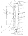
- a press connection 10 is partially shown with a press jaw 12 shown schematically.
- the pressing jaw 12 has pressing contours 12b and a positioning auxiliary contour 12a.
- Reverted areas 12c which are set back relative to the pressing surfaces 12b relative to the surface of the compression sleeve 14, are usually inactive during a pressing operation, while the pressing contours plastically deform the compression sleeve. This is different with the invention.
- a generally cylindrical compression sleeve 14 is positioned over a corresponding, usually also cylindrical support sleeve 16.
- the compression sleeve 14 is held by a plastic element 20 which is engaged in a groove 26 on a collar 18 of the press connection 10 with a latching shoulder 22.
- the plastic element 20 may also have a stop shoulder 24 to which a plastic pipe or a composite pipe strikes, the is inserted into the intermediate space between the compression sleeve 14 and the support sleeve 16 for subsequent compression.
- the compression sleeve 14 has an engagement element 28 with which the compression sleeve 14 engages in a corresponding recess 31 of the plastic element 20.
- the plastic element 20 is referred to as such, but it may also be formed in the form of a metal ring with corresponding contours.
- the plastic element 20 may be made of transparent material or openings may be provided for visual inspection to control the position of the tube. Such a position control can also be provided in the compression sleeve 14 itself, for example in the form of a hole.
- the compression sleeve 14 also has on the insertion side or postponement side for the plastic pipe or composite pipe on an extension region 32, so that the insertion of a plastic pipe can be facilitated.
- the compression sleeve 14 has radial, fully formed extensions 30, which can serve on the one hand to facilitate the positioning by means of the extension 12a on the mold jaw 12 for the pressing tool on the press connection according to the invention and on the other hand, that by the arrangement of the extensions 30 via Seal elements 34a, 34b of the support sleeve 16 in the region of the sealing elements 34a, 34b, O-ring seals according to the invention, a particularly defined compression can accomplish.
- a compression in this area is also possible because of this configuration with any pressing jaws, because the extensions 30 may have such a radial extent that regardless of the existence of pressing contours 12b compression can be generated by a pressing jaws.
- the support sleeve 16 has at its deferred end a special contour, which is used to calibrate a pipe with a certain diameter and a certain diameter tolerance. This becomes even more precise with respect to the Fig. 3 be explained.
- the contour 48 has an outer diameter which increases in the direction of displacement in order to carry out a calibration. Constrictions, notches 44 or the like, may serve to provide a sharp edge on the inner circumference of a tube to be pushed partially ablate and thereby defuse, so that the injury of the O-rings is unlikely.
- prongs 42 are arranged, whose outer diameter is lower than the largest outer diameter of the calibrating end 46 of the support sleeve 16.
- a prong In the immediate vicinity of the first O-ring seal 34b is a prong with a slightly larger outer diameter, but still has a slightly smaller outer diameter as the O-ring seal 34b, so that the O-ring seal 34b is not fully received in a groove 40b, which connects to the front teeth of the support sleeve.
- a ridge 38 is arranged, which preferably also has an at least slightly smaller radial extent, as the O-ring seals themselves. The same applies to the groove 40a with respect to the O-ring seal 34a.
- the groove 40a To the O-ring seal 34a and thus the groove 40a include further prongs 36, which may be the same but also formed differently.
- a plastic tube which is inserted between the compression sleeve 14 and the support sleeve 16, abut the stop 24 of the plastic part 20 and will not receive direct contact with the collar 18, which is particularly valuable if it is the plastic pipe is a composite pipe, the metal layer of the metal material of the support sleeve 16 and the collar 18 is to be kept away to avoid corrosive phenomena.
- the support sleeve or the collar can also be provided with a radial extent, which forms a stop, wherein the stop is to be regarded as belonging to the collar 18.
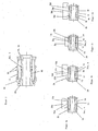
- Fig. 2 is in principle the press connection according to Fig. 1 shown, but here the cylindrically symmetrical design of the elements is better apparent, with reference to Fig. 1 have been explained in detail.
- the Fig. 2a to 2d show different geometries of known pressing jaws and it can be seen that with these different geometries a compression of the press connection according to the invention is possible, if possible with equally good results. This is particularly advantageous since the user of the press connection according to the invention, of course, with his existing at him Press jaw geometry, no matter what known type this, in this way the press connection according to the invention without loss of holding power, strain relief, tightness and the like. More can perform a press connection. It is essential that the radially outward extensions 30 dimensioned to fit to press tools with any pressing contour by the extensions reach 30 before or during the pressing process in contact with the press contour to be at least partially acted upon by a pressing pressure.
- an F-contour 50a is shown schematically, which has respective pressing structures 52a at its outer regions, while between the pressing structures 52a a region which is in principle inactive and which is not used for a compression.
- the radial extensions 30 of the compression sleeve are important, since a defined higher pressing force can be exerted on the compression sleeve in order to deform it in the area of the O-ring seals.
- a contour 50b is shown, which is formed symmetrically as well as the contour 50a in the axial direction of the press connection.
- pressing structures 52b are provided which, in principle, would not act on the O-ring seals 30a, 30b, so that a compression in the area of the seals would not occur.
- the radial extensions 30 on the compression sleeve have a particular significance, namely, in turn, a compression function can be achieved by the otherwise in principle inactive pressing surface 54b of the pressing jaw 50b.
- the pressing jaw 50b also has an adjustment contour 56b, which however is not used.
- a pressing jaw 50c is set with a contour. Since this contour is in principle the in Fig. 1 shown here, this will not be discussed further here. It should merely be noted that here as well, in principle, the pressing inactive surface 12c of the pressing jaw, in principle, exerts a compressive and thus deforming action on the pressing sleeve and in consequence on the plastic tube, over the extension 30 of the pressing sleeve 14.
- a B-contour 50d is shown, which in turn is formed symmetrically and which in turn has a structure 56d as a positioning aid corresponding to the plastic element 20.
- Press structures 52d are provided and act on the compression sleeve 14 for compression.
- An inactive for the pressing surface 54d is activated for the pressing process by the extensions 30 of the compression sleeve.
- the compression sleeve 14 has two circumferential radially outward extensions 30, which are each positioned over a portion of the support sleeve 16 which carries a ring seal, wherein for pressing by a pressing contour of a pressing tool certain peripheral surfaces of the compression sleeve 14 in the axial direction are arranged, which are plastically deformed radially inwardly by a pressing operation.
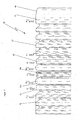
- the Fig. 3 shows an exemplary surface contour of a support sleeve 16, as may be formed according to the invention. Accordingly, at the deferred end 46 of the support sleeve, a calibrating contour 48 can be seen, the outer circumference increases to 25.9 mm, for a réelleschiebendes tube with a diameter of 26 mm, within the tolerances tube diameter with 25.8 to 26.2 mm are possible. Calibration occurs here via the bevel 48 and the larger diameter following the slope in the push-on side of the plastic tube. As shown, the subsequent prongs 42 are dimensioned smaller in their diameter or in their radial extent, with 25.7 mm.
- a prong 43 immediately adjacent to the front O-ring seal is formed with a smaller outer diameter or radial extent, here by way of example 25.5 mm.
- the O-ring seal subsequently has a larger outside diameter, in this case by way of example 25.9 mm.
- the O-ring seal protrudes beyond both the adjacent serrations 43 discussed above and the serrations 42 formed therebefore.
- a ridge 38b which is formed with a groove, which may have a depth of about 3 to 6 mm.
- This groove or depression serves to be able to absorb material displaced by the pressing, in such a way that by pressing with one of the mold jaws according to the Fig. 2a to 2d displaced material not excessive acts heavily on the O-ring seals to prevent their excessive deformation or even damage. Accordingly, the small radial extension of the prong 43 is motivated.
- the peripheral ridge 38b is followed by another O-ring seal 34a, which is received in a groove. The sizing of these components corresponds to the sizing of the corresponding components discussed above.
- the O-ring seal 34a is adjoined by a ridge having rounded, rectangular contours and an outer diameter corresponding to that of the serration 43 and the maximum radial extent of the ridge 38b, respectively.
- the subsequent prongs 36 in turn have approximately the dimensions of the prongs 42.
- the dimensions of the support sleeve 16 are to be modified accordingly, again corresponding manufacturing tolerances of the plastic pipes or composite pipes to be considered in order to achieve the desired leakage function.
- an annular gap of approximately 1 mm should be provided on average, but this is relatively difficult in view of the manufacturing tolerances for production pipes or composite pipes.
- a completed piping system is subjected to the construction of a piping system with press connections with a pressure of up to 10 bar (1 MPa), so that in such a case, of course, a non-compressed connection due to the leakage function is leaking anyway and reveals itself to the craftsman.
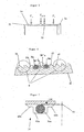
- the Fig. 4 shows a formation of a press connection, which substantially corresponds to the structures discussed above. It can be seen that here a coupling has two support sleeves 16a, 16b, which, however, when viewed in each case are approximately the same, so that their discussion can be dispensed with. It should only be noted that a in pushing plastic tube at its end, already deferred end has a deburring structure 2, which serves to avoid injury to the above O-rings.
- Fig. 4a is the section X according to Fig. 4 illustrated, this section can be seen that the structure of the support sleeve 16 substantially similar to those of the preceding structures.
- a deviation is only recognizable in view of the fact that already several of the serrations 42 ', 43' in the direction of advancement in front of the first O-ring seal 34b have a smaller diameter or a smaller radial extent, over which the O-ring 34b protrudes.
- the ridge 38a ' has another contour which projects in longitudinal section, the purpose of the larger groove 38b' being that, as the tube is deformed by the pressing operation, more material is to be received to prevent excessive compression of the O-ring seals 34a ', 34b to avoid.
- one of the O-ring seal 34a 'following prongs 37a is slightly modified by its leading edge in the advancing direction has a smaller diameter or a smaller radial extent, while the trailing edge is serrated with a larger outer diameter, on the one hand in the compression be able to accommodate sufficient material of the plastic pipe, and on the other hand to be able to develop a holding power.
- a subsequent region of the prongs 36 is formed with a smaller outer diameter, as in this area no sealing function or Buchentlastungs- or -haltefunktion must be applied.
- Fig. 5 It is shown how pressing forces act on a compression sleeve 14 of a press connection according to the invention.
- the pressing jaws 50a according to FIG Fig. 2a used.
- the contour 54a of the pressing jaw 50a would be passive. However, due to the formation of the radial extensions 30, the contour 54a of the pressing jaw 50a also brings forces, which are shown in the illustration with F 2/3 .
- the Fig. 6 shows an embodiment of a support sleeve with again slightly different structures formed.
- the structures separately with The reference numeral 8 are used to record material of the compressed tube for the different trained and used press jaw contours, on the one hand to allow a fixation of the tube and on the other hand a permanent sealing of the tube without damaging the O-ring seals become. Accordingly, the ridge 38a "slightly modified here and also the contours the serrations 37b and 43 are slightly modified.
- a leakage gap 41 is shown, which makes up about 1 mm. But it can also be in the range of 0 to 2 mm, but also more or less, in which case in the corresponding case, a higher pressure must be applied in order to perform the leakage function can.
Description
Die Erfindung betrifft eine Pressverbindung zum Anschließen von Kunststoffrohren mit einer Stützhülse, auf die ein anzuschließendes Rohr aufgeschoben wird, mit einer Presshülse, durch deren Verformung das Kunststoffrohr auf der Stützhülse festgelegt wird sowie mit einem Kunststoffrohr, das in einen zylindrischen Spalt zwischen der Stützhülse und der Presshülse eingeführt wird, gemäß dem Anspruch 1.The invention relates to a press connection for connecting plastic pipes with a support sleeve on which a pipe to be connected is pushed, with a compression sleeve, by the deformation of the plastic tube is fixed to the support sleeve and with a plastic tube in a cylindrical gap between the support sleeve and the Press sleeve is introduced, according to claim 1.
Eine im Stand der Technik bekannte Pressverbindung, die auf die Verpressung mittels bestimmt ausgebildeter Pressbacken einer Presszange ausgerichtet ist, weist eine Dichtungskonstruktion auf, bei der die Dichtungen vollkommen eben in Aufnahmenuten aufgenommen sind. Diese Dichtungen ragen nicht über die Stützhülse hinaus, so dass eine besonders heftige Verformung der Presshülse durchgeführt werden muss, um das Material eines zu verpressenden Kunststoffrohres oder Kunststoff-Metall-Kunststoff-Verbundrohres, kurz Verbundrohr genannt, in eine ausreichende Anlage zu den O-Ring-Dichtungen zu verbringen. Hierdurch können die O-Ringdichtungen leicht beschädigt werden und die Presszange muss einen besonders hohen Pressdruck aufbringen, der die Presszange sehr beansprucht. Durch diese gemäß der
Gemäß der
Aus diversen anderen Druckschriften aus dem Stand der Technik, der
Die
Ferner ist es eine bevorzugte Aufgabe gemäß der Erfindung ein Pressfitting zur Verfügung zu stellen, der mit diversen verschiedenen Presswerkzeugen bzw. Pressbacken von Presswerkzeugen verpresst werden kann, wobei sowohl die Leckagefunktion als auch eine sichere Abdichtung durch die Verpressung ermöglicht werden kann.Furthermore, it is a preferred object according to the invention to provide a press fitting which is provided with various different pressing tools Pressing or pressing of pressing tools can be pressed, both the leakage function and a secure seal can be made possible by the compression.
Es ist die Aufgabe gemäß der vorliegenden Erfindung, eine Verbindung zum Anschließen von Kunststoffrohren und insbesondere für Verbundrohre zur Verfügung zu stellen, die eine Leckagefunktion ermöglicht, wobei gleichzeitig eine sichere Abdichtung der Verbindung nach dem Verpressen und damit Festlegen des Kunststoffrohres bzw. Verbundrohres ermöglicht wird.It is the object according to the present invention to provide a connection for the connection of plastic pipes and in particular for composite pipes, which allows a leakage function, at the same time a secure sealing of the connection after pressing and thus fixing the plastic pipe or composite pipe is made possible.
Gemäß der Erfindung wird wenigstens eine der genannten Aufgaben durch eine Pressverbindung gemäß dem Anspruch 1 gelöst. Zweckmäßige Ausführungsformen gehen aus den Unteransprüchen hervor.According to the invention, at least one of said objects is achieved by a press connection according to claim 1. Advantageous embodiments will become apparent from the dependent claims.
Es kann an eine Pressverbindung für Kunststoffrohre gedacht werden, die mit den folgenden Merkmalen ausgebildet ist:
- einer Stützhülse, auf die ein aufzuschiebendes Rohr aufgeschoben wird,
- einer Presshülse, durch deren Verformung das Kunststoffrohr auf der Stützhülse festgelegt wird; mit einem Kunststoffrohr oder Kunststoff-Metall-Kunststoff-Verbundrohr, das in einen zylindrischen Spalt zwischen der Stützhülse und der Presshülse einführbar ist; einem Bund mit einem Anschlag am Ende der Stützhülse, gegen den das Kunststoffrohr nach dem Aufschieben mit oder ohne Abstand zu liegen kommt, dadurch gekennzeichnet, dass
- die Presshülse zwei umfängliche radial auswärts gerichtete Erstreckungen aufweist, die jeweils über einem Bereich der Stützhülse positioniert sind, der eine O-Ringdichtung trägt, wobei
- für eine Verpressung durch eine Presskontur eines Presswerkzeuges bestimmte Umfangsflächen der Presshülse in deren Axialrichtung angeordnet sind, die durch einen Pressvorgang plastisch radial einwärts deformierbar sind.
- a support sleeve onto which a tube to be pushed is pushed
- a compression sleeve, the deformation of which sets the plastic tube on the support sleeve; with a plastic tube or plastic-metal-plastic composite tube, which is insertable into a cylindrical gap between the support sleeve and the compression sleeve; a collar with a stop at the end of the support sleeve, against which the plastic pipe comes to rest after pushing with or without a distance, characterized in that
- the compression sleeve has two circumferential radially outward extensions, each positioned over a portion of the support sleeve carrying an O-ring seal, wherein
- for pressing by a pressing contour of a pressing tool certain peripheral surfaces of the compression sleeve are arranged in the axial direction, which are plastically deformed radially inwardly by a pressing operation.
Gemäß einer bevorzugten Ausführungsform dieser Pressverbindung sind die radial auswärts gerichteten Erstreckungen dimensioniert, um zu Presswerkzeugen mit beliebiger Presskontur zu passen, indem die Erstreckungen vor oder beim Verpressvorgang in Anlage zur Presskontur gelangen, um wenigstens teilweise mit einem Pressdruck beaufschlagbar zu sein.According to a preferred embodiment of this press connection, the radially outwardly extending extensions are dimensioned to fit pressing tools of any desired pressing contour, in that the extensions come into contact with the pressing contour before or during the pressing operation in order to be at least partially acted upon by a pressing pressure.
Gemäß der Erfindung wird das Kunststoffrohr, das mit der Pressverbindung festzulegen ist, einen gleichen oder minimal größeren Innendurchmesser aufweisen, verglichen mit dem Außendurchmesser mit der Stützhülse in einem umfänglichen Bereich der Stützhülse, der axial zur Pressverbindung bzw. der Stützhülse begrenzt ist, so dass dieser auf die Umgebung einer O-Ringdichtung begrenzt ist, wobei die O-Ringdichtung einen minimal größeren Außendurchmesser als die Stützhülse außerhalb des Bereiches hat.According to the invention, the plastic pipe to be fixed with the press connection will have an equal or minimally larger inner diameter compared to the outer diameter with the support sleeve in a circumferential region of the support sleeve which is axially limited to the press connection or support sleeve, so that this is limited to the environment of an O-ring seal, wherein the O-ring seal has a minimally larger outer diameter than the support sleeve outside the range.
Durch diese Ausgestaltung ist es möglich, mit oder ohne einen Überdruck innerhalb eines Kunststoffrohres das Austreten von Flüssigkeit zu erkennen, so dass ein Handwerker anhand dieses Signals erkennen kann, dass die betreffende Pressverbindung noch nicht verpresst worden ist. Bei dieser Ausgestaltung ist es zwar nötig, das aufzuschiebende und festzulegende Kunststoffrohr zu entgraten, jedoch ist es bei dieser erfindungsgemäßen Ausgestaltung möglich, beim Verpressen der Pressverbindung das Material der Presshülse und damit des Kunststoffrohres nicht so weit radial nach innen auslenken zu müssen, um einen dichtenden Kontakt zwischen den O-Ringdichtungen und dem Innendurchmesser des Kunststoffrohres herzustellen, dass unter Umständen die O-Ringe verletzt werden könnten oder dass die Presszange eine besonders große Presskraft aufzubringen hat. Jedenfalls ist es für eine dichte Verbindung nicht erforderlich, eine größere Menge des Materials des Kunststoffrohres in die Nuten der O-Ringdichtungen hinein zu verpressen.With this configuration, it is possible to detect the escape of liquid with or without an overpressure within a plastic tube, so that a craftsman can recognize on the basis of this signal that the relevant press connection has not yet been pressed. In this embodiment, it is indeed necessary to deburr the aufzuschiebende and fixed plastic pipe, but it is possible in this embodiment of the invention, when compressing the press connection, the material of the compression sleeve and thus of the plastic pipe so far does not have to deflect radially inward to a sealing Make contact between the O-ring seals and the inner diameter of the plastic tube, that under certain circumstances, the O-rings could be injured or that the pressing tongs have to apply a particularly large pressing force. In any case, it is not necessary for a tight connection, to press a larger amount of the material of the plastic tube in the grooves of the O-ring seals into it.
Vorteilhafterweise hat die Presshülse eine umfängliche, radial auswärts gerichtete Erstreckung, die über dem Bereich der Stützhülse positioniert ist. Dieses Merkmal hat zwei Vorzüge, nämlich einerseits, dass auch Pressbacken für die Verpressung der Pressverbindung verwendet werden können, die keine Pressfläche im Bereich der O-Ringe der Pressverbindung aufweisen, sondern daneben. Durch diesen umfänglichen Erstreckungsbereich der Presshülse kann auch mit einem radial einwärts positionierten Bereich einer Pressbacke eines Presswerkzeuges eine Kraft auf die Presshülse ausgeübt werden, unabhängig davon, dass die Pressflächen der Pressbacken des Presswerkzeuges axial gesehen an einer anderen Stelle angeordnet sind. Der radiale Abstand zwischen dem Presswerkzeug bzw. dessen Pressbacken und der zu verpressenden Oberfläche der Presshülse wird hier nicht durch die Pressflächen der Pressbacken überwunden, sondern durch die radial auswärts gerichtete Erstreckung der Presshülse. Ferner ist es möglich, diese Erstreckung auch zur Justierung der Pressbacken des Presswerkzeuges bzw. der Presszange in axialer Richtung in Bezug auf die Presshülse bzw. die Pressverbindung eingesetzt werden. Weist die radiale Erstreckung beispielsweise zwei ringartig umlaufende Erhöhungen auf, kann ein Positionierungshilfeansatz an dem Innenumfang der Pressbacken genau in den axialen Zwischenraum zwischen den umfänglich verlaufenden Erstreckungen passen, um so von Pressverbindung zu Pressverbindung reversibel die Pressbacken bzw. das Presswerkzeug platzieren zu können.Advantageously, the compression sleeve has a circumferential, radially outward extension, which is positioned over the region of the support sleeve. This feature has two advantages, namely on the one hand that pressing jaws can be used for the pressing of the press connection, which have no pressing surface in the area of the O-rings of the press connection, but next to it. A force can also be exerted on the compression sleeve by means of this circumferential extension region of the compression sleeve, even with a region of a pressing jaw of a pressing tool positioned radially inward, regardless of the fact that the pressing surfaces of the pressing jaws of the pressing tool are arranged at a different location in an axial direction. The radial distance between the pressing tool or its pressing jaws and the surface to be pressed of the compression sleeve is not affected by the pressing surfaces of the Pressing jaws overcome, but by the radially outward extension of the compression sleeve. Furthermore, it is possible to use this extension also for adjusting the pressing jaws of the pressing tool or the pressing tool in the axial direction with respect to the pressing sleeve or the press connection. If, for example, the radial extension has two annularly extending elevations, a positioning aid approach on the inner circumference of the pressing jaws can fit precisely in the Axial space between the circumferentially extending extensions fit so as to be able to place the press jaws and the pressing tool reversibly from press connection to press connection.
Vorteilhafterweise hat die Stützhülse einer anderen Ausführungsform an ihrem dem Bund abgewandten Ende einen Außenumfang, der relativ zum Innenumfang des Kunststoffrohres größer ist, um zu dessen Kalibrierung und/oder Entgratung beizutragen. D.h., das entsprechend abgewandte Ende der Stützhülse kann konisch in Aufschubrichtung breiter werden, kann aber auch mit einem gewissen vorgebbaren Radius weiter werden, um das aufzuschiebende Rohr, das gewisse Fertigungstoleranzen aufweist, in Bezug auf die Stützhülse zu kalibrieren. Ferner ist es möglich, in dem Bereich der Kalibrierung Rillen, Riefen oder dgl. vorzusehen, so dass eine besonders scharfe Kante des aufzuschiebenden Rohres bearbeitet werden kann. Hier kann beispielsweise durch einen abspanenden Vorgang oder durch einen abreibenden Vorgang die besonders scharfe Kante eines aufzuschiebenden Kunststoffrohres entschärft werden, wobei sich die Rillen oder dgl. auch mit dem Material des Rohres bzw. dessen Stirnfläche zusetzen können. Die Gefahr einer Verletzung der O-Ringdichtungen kann auf diese Weise auch gemildert werden.Advantageously, the support sleeve of another embodiment has at its end facing away from the collar an outer periphery which is larger relative to the inner circumference of the plastic tube in order to contribute to its calibration and / or deburring. In other words, the correspondingly opposite end of the support sleeve can become wider conically in the push-on direction, but can also continue to be of a certain predeterminable radius in order to calibrate the tube to be pushed on, which has certain manufacturing tolerances, with respect to the support sleeve. Furthermore, it is possible to provide grooves, grooves or the like in the area of the calibration, so that a particularly sharp edge of the pipe to be pushed onto can be machined. Here, for example, by a chipping process or by an abrading process, the particularly sharp edge of a plastic pipe aufzuschiebenden be defused, with the grooves or the like. Can also enforce with the material of the pipe or its end face. The risk of injury to the O-ring seals can also be mitigated in this way.
Wie bereits angedeutet, kann die Presshülse eine äußere Kontur aufweisen, die zu einer Anzahl von Pressbacken von Presszangen in eine justierende Korrespondenz bringbar ist. Dabei kann vorteilhafterweise die Presshülse über ein Halteelement, beispielsweise aus Metall oder Kunststoff, am Bund der Pressverbindung gehalten werden, wobei das Halteelement eine Außenkontur aufweist, die zu wenigstens einer Pressbackengeometrie korrespondiert, um eine bezüglich der Verpressungsposition kontrollierte Verpressung der Presshülse gegenüber der Stützhülse vornehmen zu können. Dabei bietet es sich an, dass dieses Halteelement aus durchsichtigem Kunststoff ist, wenigstens eine Öffnung hat, oder dgl., so dass die Lage eines Rohres in dem Zwischenraum zwischen der zylindrischen Stützhülse und der zylindrischen Presshülse nahe dem Bund bzw. am Bund überprüfbar ist. Auch die Presshülse selbst kann mit einer Öffnung versehen sein, so dass die Lage eines Kunststoffrohres vor der Verpressung oder sogar bei der Verpressung in der Pressverbindung erkennbar ist.As already indicated, the compression sleeve can have an outer contour which can be brought to a number of pressing jaws of pressing tongs in an adjusting correspondence. In this case, advantageously, the compression sleeve via a holding element, for example made of metal or plastic, are held on the collar of the press connection, wherein the holding element has an outer contour which corresponds to at least one pressing jaw geometry to make a respect to the pressing position controlled compression of the compression sleeve relative to the support sleeve can. It is advisable that this holding element is made of transparent plastic, has at least one opening, or the like., So that the position of a tube in the space between the cylindrical support sleeve and the cylindrical compression sleeve near the collar or verifiable at the federal level. Also, the compression sleeve itself may be provided with an opening, so that the position of a plastic tube before compression or even during compression in the press connection can be seen.
Bevorzugt weist der umfängliche Bereich der Stützhülse zwei axial beabstandete Richdichtungen oder O-Ringdichtungen auf. Dementsprechend ist es auch günstig, wenn die Presshülse jeweilige zugeordnete radiale Erstreckungen aufweist, die den Ringdichtungen oder O-Ringdichtungen zuordenbar sind. Natürlich können beide O-Ringdichtungen auch mit einer einzigen umfänglichen, radial auswärts gerichteten Erstreckung verpresst werden, wobei aber eine solche einzelne Erstreckung einer bekannten Pressbackenstruktur, der U-Kontur nicht entspräche, so dass eine Verpressung mit einer solchen Pressbacke nicht möglich wäre.Preferably, the circumferential region of the support sleeve on two axially spaced rich seals or O-ring seals. Accordingly, it is also advantageous if the compression sleeve has respective associated radial extensions, which can be assigned to the ring seals or O-ring seals. Of course, both O-ring seals can be pressed with a single circumferential, radially outward extension, but such a single extension of a known press jaw structure, the U-shape would not correspond, so that a compression with such a pressing jaw would not be possible.
Zu bevorzugen ist es, wenn zwei O-Ringdichtungen in jeweilige umfängliche Nuten in der Stützhülse aufgenommen sind, wobei die beiden Nuten durch einen umfänglichen Grat getrennt sind, der eine umfängliche Nut aufweist. Diese Struktur des Grats zwischen den O-Ringdichtungen dient zur Bereitstellung einer speziellen Stützkörpergeometrie für die Stützhülse, um bei einer Verpressung mit diversen unterschiedlichen Pressbacken, wie der F-Kontur, der TH-Kontur, der U-Kontur und der B-Kontur, ein definiertes Verpressungsergebnis bereitstellen zu können, wobei die O-Dichtringe nicht zerquetscht oder beschädigt werden dürfen.It is preferable that two O-ring seals are received in respective circumferential grooves in the support sleeve, the two grooves being separated by a circumferential ridge having a circumferential groove. This structure of the ridge between the O-ring seals serves to provide a special support body geometry for the support sleeve to interlock with a variety of pressing jaws, such as the F-contour, the TH contour, the U-contour and the B-contour be able to provide defined pressing result, the O-rings may not be crushed or damaged.
Natürlich können beliebig ausgebildete d.h. O-Ringdichtungen im Rahmen der Erfindung eingesetzt werden.Of course, arbitrarily formed, i. O-ring seals are used in the invention.
Die erfindungsgemäße Stützhülse weist umfängliche Zacken auf, die in der Nachbarschaft zu dem bzw. zu den O-Ringdichtungen eine geringere radiale Erstreckung aufweisen als entfernt von den O-Ringdichtungen. Auf diese Weise ist es während des Verpressvorganges einfacher, einen Materialtransport beim Verpressen zu ermöglichen, so dass Kunststoffmaterial des Kunststoffrohres bzw. des Verbundrohres in einen dichtenden Kontakt zu den O-Ringdichtungen gelangen kann.The support sleeve according to the invention has circumferential prongs, which in the vicinity of the or to the O-ring seals have a smaller radial extent than remote from the O-ring seals. In this way it is easier during the pressing process to allow material transport during compression, so that plastic material of the plastic tube or the composite tube can come into sealing contact with the O-ring seals.
Bevorzugt ist ein umfänglicher Zacken der Stützhülse in Aufschubrichtung des Kunststoffrohres vor der/vor den O-Ringdichtung(en) in Axialrichtung der Stützhülse wenigstens teilweise mit einer geringeren radialen Erstreckung ausgebildet als andere umfängliche Zacken der Stützhülse. Ferner ist es möglich, vorteilhafterweise einen umfänglichen Zacken der Stützhülse in Aufschubrichtung des Kunststoffrohres hinter der/den O-Ringdichtung(en) in Axialrichtung der Stützhülse wenigstens teilweise eine geringere radiale Erstreckung aufweisen zu lassen als andere umfängliche Zacken der Stützhülse. Auch durch eine derartige Ausbildung ist es möglich, durch eine nicht zu intensive Verpressung der Stützhülse einen festen, dauerhaften oder dichten Kontakt zwischen der Innenwand des Kunststoffrohres und den O-Ringdichtungen zu bewerkstelligen.Preferably, a circumferential teeth of the support sleeve in the direction of the plastic tube in front of the O-ring seal (s) in the axial direction of the support sleeve is at least partially formed with a smaller radial extent than other circumferential teeth of the support sleeve. Further, it is possible, advantageously, a circumferential point the support sleeve in the direction of retraction of the plastic tube behind the / O-ring seal (s) in the axial direction of the support sleeve at least partially have a smaller radial extent than other circumferential teeth of the support sleeve. Also, by such a design, it is possible to accomplish by not too intense compression of the support sleeve a solid, permanent or tight contact between the inner wall of the plastic tube and the O-ring seals.
Da beispielsweise im Hinblick auf die Leckagefunktion der Pressverbindung durchaus auch die Maße der Stützhülse, des Kunststoffrohres und der Presshülse eine Rolle spielen, ist darauf hinzuweisen, dass auch die konkreten Maße durchaus eine erfinderische Qualität aufweisen können, wie sie auch aus der nachfolgenden Figurenbeschreibung bzw. den nachfolgend aufgeführten Figuren hervorgehen.Since, for example, the dimensions of the support sleeve, the plastic tube and the compression sleeve also play a role, for example with regard to the leakage function of the press connection, it must be pointed out that the concrete dimensions can also have an inventive quality, as is also apparent from the following description of the figures and the following figures emerge.
So sind Kunststoffrohre mit unterschiedlichen Innen- bzw. Außendurchmesser mit unterschiedlichen Fertigungstoleranzen herstellbar. Ein Rohr mit einem Durchmesser von 26 mm kann z.B. innerhalb einer Fertigungstoleranz von 25,8 bis 26,2 mm produziert werden, so dass entsprechend hier ein O-Ring mit einem Außendurchmesser von 25,8 bzw. 25,9 mm zur Verfügung gestellt werden muss, um einen Ringspalt in dem Sinne bereitstellen zu können, dass die gewünschte Leckagefunktion vorteilhaft erreicht wird. Eine Leckagefunktion außerhalb der genannten Maße ist zwar auch möglich, jedoch wird die Funktion in dem genannten Bereich besonders vorteilhaft erreicht. Dementsprechend wir die Leckagefunktion für Rohre mit 16, 20 oder beispielsweise 40 mm Durchmesser in anderer Form erreicht, da einerseits diese Rohre andere Fertigungstoleranzen aufweisen und andererseits dementsprechend die Pressverbindung eine dimensionsmäßige und funktionsmäßige Anpassung erfordert.So plastic pipes with different inner or outer diameter can be produced with different manufacturing tolerances. A tube with a diameter of 26 mm may e.g. are produced within a manufacturing tolerance of 25.8 to 26.2 mm, so that here according to an O-ring with an outer diameter of 25.8 or 25.9 mm must be provided in order to provide an annular gap in the sense can be that the desired leakage function is advantageously achieved. Although a leakage function outside the stated dimensions is also possible, the function is achieved particularly advantageously in the stated range. Accordingly, we achieve the leakage function for tubes with 16, 20 or for example 40 mm diameter in another form, since on the one hand these tubes have different manufacturing tolerances and on the other hand, accordingly, the press connection requires a dimensional and functional adjustment.
Nachfolgend wird die vorliegende Erfindung anhand bevorzugter Ausführungsformen näher erläutert, wobei weitere Merkmale, Vorzüge und Zielsetzungen der Erfindung offenbart werden. In den Darstellungen zeigen:
- Fig. 1
- eine erfindungsgemäße Pressverbindung in einem teilweisen axialen Querschnitt mit angedeuteter Pressbacke;
- Fig. 2
- die Pressverbindung gemäß
Fig. 1 in einem axialen Längsschnitt; - Fig. 2a bis 2d
- die Pressverbindung gemäß
Fig. 2 mit unterschiedlichen Pressbackenkonturen von Presswerkzeugen jeweils im axialen Längsschnitt; - Fig. 3
- eine Stützhülse in einer teilweisen Seitenansicht mit Maßangaben in Millimetern;
- Fig. 4
- ein Kupplungsstück einer Pressverbindung mit Merkmalen gemäß der Erfindung in einer Seitenansicht;
- Fig. 4a
- ein Ausschnitt X gemäß
Fig. 4 in einem axialen Längsschnitt; - Fig. 5
- eine Presshülse einer Pressverbindung gemäß der Erfindung in einem teilweisen axialen Längsschnitt mit einer Andeutung der Krafteinwirkung eines Presswerkzeuges;
- Fig. 6
- ein teilweiser axialer Längsschnitt durch eine Stützhülse einer Pressverbindung gemäß der Erfindung; und
- Fig. 7
- einen axialen Längsschnitt durch eine Stützhülse mit aufgeschobenem Rohr in einer ausgeschnittenen Ansicht.
- Fig. 1
- a press connection according to the invention in a partial axial cross section with indicated pressing jaw;
- Fig. 2
- the press connection according to
Fig. 1 in an axial longitudinal section; - Fig. 2a to 2d
- the press connection according to
Fig. 2 with different press jaw contours of pressing tools each in axial longitudinal section; - Fig. 3
- a support sleeve in a partial side view with dimensions in millimeters;
- Fig. 4
- a coupling piece of a press connection with features according to the invention in a side view;
- Fig. 4a
- a section X according to
Fig. 4 in an axial longitudinal section; - Fig. 5
- a compression sleeve of a press connection according to the invention in a partial axial longitudinal section with an indication of the force of a pressing tool;
- Fig. 6
- a partial axial longitudinal section through a support sleeve of a press connection according to the invention; and
- Fig. 7
- an axial longitudinal section through a support sleeve with deferred tube in a cutaway view.
In den Darstellungen sind gleiche oder wenigstens funktionsgleiche Bestandteile mit gleichen, bzw. einander entsprechenden Bezugszeichen gekennzeichnet.In the representations, identical or at least functionally identical components are identified by the same or corresponding reference symbols.
In
Eine in der Regel zylindrische Presshülse 14 ist über einer korrespondierenden, in der Regel ebenfalls zylindrischen Stützhülse 16 positioniert. Die Presshülse 14 wird durch ein Kunststoffelement 20 gehalten, das in eine Rille 26 an einem Bund 18 der Pressverbindung 10 mit einer Rastschulter 22 eingerastet ist. Das Kunststoffelement 20 kann auch eine Anschlagschulter 24 aufweisen, an die ein Kunststoffrohr bzw. ein Verbundrohr anschlägt, das in den Zwischenraum zwischen die Presshülse 14 und die Stützhülse 16 zur nachfolgenden Verpressung eingeschoben wird.A generally
Die Presshülse 14 hat ein Eingriffselement 28, mit dem die Presshülse 14 in eine korrespondierende Ausnehmung 31 des Kunststoffelementes 20 hineingreift. Zwar ist hier das Kunststoffelement 20 als solches bezeichnet, es kann aber auch in der Form eines Metallringes mit entsprechenden Konturen ausgebildet sein. Das Kunststoffelement 20 kann aus durchsichtigem Material bestehen oder es können Öffnungen für eine Sichtkontrolle zur Lagekontrolle für das Rohr vorgesehen sein. Eine solche Lagekontrolle kann auch in der Presshülse 14 selbst vorgesehen sein, beispielsweise in der Form eines Loches.The
Die Presshülse 14 weist ferner auf der Einführseite bzw. Aufschubseite für das Kunststoffrohr oder Verbundrohr einen Erweiterungsbereich 32 auf, so dass das Einführen eines Kunststoffrohres erleichtert werden kann.The
Ferner weist die Presshülse 14 radiale, vollumfänglich ausgebildete Erstreckungen 30 auf, die einerseits dazu dienen können, die Positionierung mittels der Erstreckung 12a an dem Formbacken 12 für das Presswerkzeug an der erfindungsgemäßen Pressverbindung zu erleichtern und andererseits dazu, dass durch die Anordnung der Erstreckungen 30 über Dichtungselementen 34a, 34b der Stützhülse 16 im Bereich der Dichtungselemente 34a, 34b, erfindungsgemäß O-Ringdichtungen, eine besonders definierte Verpressung bewerkstelligen lässt. Eine Verpressung gerade in diesem Bereich ist auch deshalb aufgrund dieser Ausgestaltung mit beliebigen Pressbacken möglich, weil die Erstreckungen 30 eine solche radiale Erstreckung aufweisen können, dass unabhängig von der Existenz von Presskonturen 12b eine Verpressung durch eine Pressbacken erzeugt werden kann.Further, the
Die Stützhülse 16 weist an ihrem aufschubseitigen Ende eine spezielle Kontur auf, die zur Kalibrierung eines Rohres mit einem bestimmten Durchmesser und einer bestimmten Durchmessertoleranz dient. Dies wird noch genauer unter Bezug auf die
Zwischen den O-Ringdichtungen 34a, 34b und dem aufschubseitigen Ende 46 der Stützhülse 16 sind Zacken 42 angeordnet, deren Außendurchmesser niedriger ist, als der größte Außendurchmesser des kalibrierenden Endes 46 der Stützhülse 16. In unmittelbarer Nähe der ersten O-Ringdichtung 34b ist ein Zacken mit geringfügig größerem Außendurchmesser angeordnet, der aber immer noch einen geringfügig kleineren Außendurchmesser wie die O-Ringdichtung 34b aufweist, so dass die O-Ringdichtung 34b nicht vollständig in eine Nut 40b aufgenommen ist, die an die vorderen Zacken der Stützhülse anschließt. Zwischen den O-Ringdichtungen 34a und 34b ist ein Grat 38 angeordnet, der bevorzugt ebenfalls eine wenigstens etwas geringere radiale Erstreckung aufweist, wie die O-Ringdichtungen selbst. Entsprechendes gilt auch für die Nut 40a in Bezug auf die O-Ringdichtung 34a. An die O-Ringdichtung 34a und damit die Nut 40a schließen weitere Zacken 36 an, die gleich aber auch unterschiedlich ausgebildet sein können.Between the O-
Bei der dargestellten Ausführungsform wird ein Kunststoffrohr, das zwischen die Presshülse 14 und die Stützhülse 16 eingeschoben wird, an den Anschlag 24 des Kunststoffteils 20 anstoßen und wird einen unmittelbaren Kontakt zu dem Bund 18 nicht erhalten, was insbesondere dann wertvoll ist, wenn es sich bei dem Kunststoffrohr um ein Verbundrohr handelt, dessen Metallschicht von dem Metallmaterial der Stützhülse 16 und des Bundes 18 ferngehalten werden soll, um korrosive Erscheinungen zu vermeiden. Natürlich kann die Stützhülse bzw. der Bund ebenfalls mit einer radialen Erstreckung versehen sein, die einen Anschlag bildet, wobei der Anschlag als zu dem Bund 18 zugehörig anzusehen ist.In the illustrated embodiment, a plastic tube which is inserted between the
In
In
In
Gemäß
Letztlich wird in
Die
Im Anschluss an die vordere O-Ringdichtung, die in einer Nut teilweise aufgenommen ist, schließt ein Grat 38b an, der mit einer Nut ausgebildet ist, die eine Tiefe von ca. 3 bis 6 mm haben kann. Diese Rille oder Vertiefung dient dazu, durch die Verpressung verdrängtes Material aufnehmen zu können, dergestalt, dass durch eine Verpressung mit einem der Formbacken gemäß der
Es ist leicht erkennbar, dass abhängig vom anzuschließenden Rohrdurchmesser die Dimensionen der Stützhülse 16 entsprechend abzuändern sind, wobei wieder entsprechende Fertigungstoleranzen der anzuschließenden Kunststoffrohre bzw. Verbundrohre in Betracht zu ziehen sind um die gewünschte Leckagefunktion zu erzielen. Bevorzugt sollte im Mittel in etwa ein Ringspalt von ca. 1 mm vorgesehen sein, was aber im Hinblick auf die Fertigungstoleranzen für Fertigungsrohre bzw. Verbundrohre relativ schwierig ist. Jedoch ist es möglich, derlei Toleranzen durch eine Druckerhöhung des Mediums innerhalb der Leitung zu überwinden, was in der Praxis vor Inbetriebnahme regelmäßig durchgeführt werden muss. Ein fertiggestelltes Leitungssystem wird nach dem Bau eines Leitungssystems mit Pressverbindungen mit einem Druck von bis zu 10 bar (1 MPa) beaufschlagt, so dass in einem solchen Falle natürlich eine nicht verpresste Verbindung aufgrund der Leckagefunktion jedenfalls undicht wird und sich dem Handwerker zu erkennen gibt.It is easily recognizable that, depending on the pipe diameter to be connected, the dimensions of the
Die
In
Die
In der
Claims (12)
- Press-fit connection for plastics pipes having the following features:- a support sleeve (16) onto which a pipe (100) to be pushed on is pushed,- a press-fit sleeve (14) which fastens the plastics pipe to the support sleeve when said sleeve is deformed;- comprising a plastics pipe (100) or plastics-metal-plastics composite pipe which is introduced into a cylindrical gap between the support sleeve (16) and the press-fit sleeve (14);- a collar comprising a stop at the end of the support sleeve, against which collar the plastics pipe lies with or without a clearance after it has been pushed on;- the plastics pipe has an internal diameter which is the same as, or minimally larger by comparison with, the external diameter of the support sleeve (16) in a circumferential region of the support sleeve, which region is axially delimited with respect to the press-fit connection and the support sleeve, such that said region is restricted to the area surrounding an O-ring seal (34a, 34b), the O-ring seal having an external diameter which is minimally larger than the support sleeve outside the region,
characterised in that the support sleeve (16) comprises circumferential teeth (42, 36) which have a smaller radial extension in the vicinity of the O-ring seal(s) (34a, 34b) than at a distance from the O-ring seals. - Press-fit connection according to claim 1, characterised in that the press-fit sleeve (14) has a circumferential extension (30) which is oriented radially outwardly and is positioned over the region of the support sleeve (16).
- Press-fit connection according to claim 2, characterised in that the support sleeve (16) has an external circumference (46, 48, 44) at the end thereof facing away from the collar (18) that is larger than the internal circumference of the plastics pipe or composite pipe in order to contribute to the calibration and/or deburring thereof.
- Press-fit connection according to any of the preceding claims, characterised in that the press-fit sleeve (14) has an external contour (30) which can be brought into correspondence with a number of press-fit jaws of press-fit teeth.
- Press-fit connection according to any of the preceding claims, characterised in that the press-fit sleeve (14) is retained on the collar by a retaining element (20).
- Press-fit connection according to either claim 4 or claim 5, characterised in that the press-fit sleeve (14) has an alignment contour (30) over at least part of the circumference thereof, preferably over the entire circumference thereof, which is used for the controlled positioning of a pressing tool.
- Press-fit connection according to claim 6, characterised in that the alignment contour (30) has a radial extension such that the surface of press-fit jaws of a pressing tool comes into contact with the alignment contour in order to produce contact for pressing the press-fit sleeve (14) in the region of the alignment contour.
- Press-fit connection according to any of the preceding claims, characterised in that the circumferential region of the support sleeve (16) receives two O-ring seals (34a, 34b) which are at an axial distance from one another.
- Press-fit connection according to claim 8, characterised in that one common circumferential extension or respective circumferential extensions (30), which is/are oriented radially outwardly on the press-fit sleeve (14), is/are assigned to the two O-ring seals (34a, 34b).
- Press-fit connection according to either claim 8 or claim 9, characterised in that the two O-ring seals (34a, 34b) are received in respective circumferential grooves (40a, 40b) in the support sleeve, the two grooves being separated by a circumferential burr (38; 38a, 38b) which has a circumferential groove.
- Press-fit connection according to any of the preceding claims, characterised in that a circumferential tooth of the support sleeve (16) has, at least in part, a smaller radial extension in the push-on direction of the plastics pipe or composite pipe in front of the O-ring seal(s) (34a, 34b) in the axial direction of the support sleeve than other circumferential teeth of the support sleeve.
- Press-fit connection according to any of the preceding claims, characterised in that a circumferential tooth of the support sleeve (16) has, at least in part, a smaller axial extension in the push-on direction of the plastics pipe or composite pipe behind the O-ring seal(s) (34a, 34b) than other circumferential teeth of the support sleeve.
Priority Applications (1)
| Application Number | Priority Date | Filing Date | Title |
|---|---|---|---|
| PL05023515T PL1653142T3 (en) | 2004-10-28 | 2005-10-27 | Press-fitting |
Applications Claiming Priority (1)
| Application Number | Priority Date | Filing Date | Title |
|---|---|---|---|
| DE102004052390.8A DE102004052390B4 (en) | 2004-10-28 | 2004-10-28 | Press connection with multiple functions |
Publications (2)
| Publication Number | Publication Date |
|---|---|
| EP1653142A1 EP1653142A1 (en) | 2006-05-03 |
| EP1653142B1 true EP1653142B1 (en) | 2015-01-21 |
Family
ID=35708657
Family Applications (1)
| Application Number | Title | Priority Date | Filing Date |
|---|---|---|---|
| EP05023515.9A Not-in-force EP1653142B1 (en) | 2004-10-28 | 2005-10-27 | Press-fitting |
Country Status (5)
| Country | Link |
|---|---|
| EP (1) | EP1653142B1 (en) |
| DE (1) | DE102004052390B4 (en) |
| DK (1) | DK1653142T3 (en) |
| ES (1) | ES2258946T1 (en) |
| PL (1) | PL1653142T3 (en) |
Families Citing this family (12)
| Publication number | Priority date | Publication date | Assignee | Title |
|---|---|---|---|---|
| DE102006030777A1 (en) * | 2006-06-30 | 2008-01-03 | Rehau Ag + Co. | pipe connection |
| DE202006010346U1 (en) * | 2006-06-30 | 2007-11-29 | Rehau Ag + Co. | Branch fitting |
| DE202007018209U1 (en) | 2007-12-28 | 2009-05-07 | Werner, Gabriele | Connection element for a line system |
| DE102008020833A1 (en) | 2008-04-25 | 2009-11-05 | Henco Industries Nv | press connection |
| EP2136121A1 (en) * | 2008-06-09 | 2009-12-23 | Uponor Innovation Ab | Pressed fitting for a pipe, in particular plastic pipe or plastic-metal composite pipe |
| AT508386B1 (en) | 2010-02-10 | 2011-01-15 | Ke Kelit Kunststoffwerk Gmbh | DEVICE FOR CONNECTING WATER PIPES |
| DE202011004544U1 (en) | 2011-03-29 | 2011-05-26 | Ipa Produktions- Und Vertriebsges.M.B.H. | Press connection for plastic pipes |
| DE102011106369A1 (en) * | 2011-07-04 | 2013-01-10 | Voss Automotive Gmbh | Sealing arrangement for sealing a multi-layer media line |
| ITMI20121068A1 (en) * | 2012-06-19 | 2013-12-20 | Ivar Spa | FITTING FOR THE CONNECTION OF PIPES, IN PARTICULAR OF FLEXIBLE PIPES |
| DE202012102984U1 (en) * | 2012-07-19 | 2012-09-26 | Uponor Innovation Ab | Press fitting and assembly comprising a press fitting |
| DE102014216184A1 (en) * | 2014-08-14 | 2016-02-18 | Fränkische Rohrwerke Gebr. Kirchner Gmbh & Co. Kg | compression sleeve |
| CN108278427B (en) * | 2018-03-27 | 2020-04-24 | 日丰企业(佛山)有限公司 | Pipe fitting connecting device |
Family Cites Families (12)
| Publication number | Priority date | Publication date | Assignee | Title |
|---|---|---|---|---|
| DE10137078B8 (en) * | 2001-07-28 | 2005-04-14 | Uponor Innovation Ab | Press fitting for pipes |
| DE19845720C2 (en) * | 1998-10-05 | 2001-03-29 | Herz Armaturen Gmbh | Connector |
| DE19856999C2 (en) * | 1998-12-10 | 2001-06-28 | Unicor Rohrsysteme Gmbh | Connection device for a pipe |
| DE19929010C1 (en) * | 1999-06-24 | 2000-11-23 | Kirchner Fraenk Rohr | Pipe connection has a molded plastics body to hold the pipe connector with a press sleeve and a support sleeve with a free zone to allow a slight bend or tilt in the assembly |
| ES2213533T3 (en) * | 1999-10-28 | 2004-09-01 | Uponor Innovation Ab | PRESSURE ASSEMBLY HOSE SYSTEM FOR A TUBE. |
| DE10010573C1 (en) * | 2000-03-03 | 2001-03-01 | Unicor Rohrsysteme Gmbh | Pipe end closure device has pipe fitting body provided with support sleeve fitting into pipe enclosed by compression sleeve fitted around pipe end |
| DE20109548U1 (en) * | 2001-06-07 | 2002-10-17 | Franz Viegener Ii Gmbh & Co Kg | Support tube and connection arrangement |
| ATE292769T1 (en) * | 2001-07-19 | 2005-04-15 | Geberit Technik Ag | PRESS CONNECTION BETWEEN A FITTING AND A PIPE END |
| EP1316753A3 (en) * | 2001-12-03 | 2004-01-14 | Geberit Technik Ag | Connection device for at least one tubular part as well as method for creating a connection with such a connection device |
| DE50202166D1 (en) * | 2002-01-03 | 2005-03-10 | Geberit Technik Ag | Connecting device for at least one pipe part and method for producing a connection with such a connection device |
| DE20207313U1 (en) * | 2002-05-10 | 2003-09-18 | Franz Viegener Ii Gmbh & Co Kg | Connector and connector assembly |
| ITMI20030010A1 (en) * | 2003-01-08 | 2004-07-09 | Antonio Romanelli | COMPRESSION FITTING FOR PIPES. |
-
2004
- 2004-10-28 DE DE102004052390.8A patent/DE102004052390B4/en not_active Expired - Fee Related
-
2005
- 2005-10-27 DK DK05023515.9T patent/DK1653142T3/en active
- 2005-10-27 ES ES05023515T patent/ES2258946T1/en active Pending
- 2005-10-27 PL PL05023515T patent/PL1653142T3/en unknown
- 2005-10-27 EP EP05023515.9A patent/EP1653142B1/en not_active Not-in-force
Also Published As
| Publication number | Publication date |
|---|---|
| DE102004052390A1 (en) | 2006-05-04 |
| DE102004052390B4 (en) | 2016-06-02 |
| PL1653142T3 (en) | 2015-06-30 |
| EP1653142A1 (en) | 2006-05-03 |
| DK1653142T3 (en) | 2015-04-27 |
| ES2258946T1 (en) | 2006-09-16 |
Similar Documents
| Publication | Publication Date | Title |
|---|---|---|
| EP1653142B1 (en) | Press-fitting | |
| EP2057397B1 (en) | Method for the pressing of a press fitting, and pressing tool for this purpose | |
| EP1959181B1 (en) | Fitting and connection assembly with a fitting | |
| EP2236889B1 (en) | Fitting for connecting a tube | |
| EP2044359B1 (en) | Sleeve, and combination of a sleeve and a pressing tool | |
| EP1924799B1 (en) | Connector piece for an end of a round in particular tubular object | |
| EP2360405A1 (en) | Tube connection device | |
| WO2011029687A1 (en) | Screwed pipe joint and method for the production thereof | |
| WO2018167158A1 (en) | Fitting for connecting to at least one pipe and method for producing a connection | |
| EP2153917A2 (en) | Spreader tool for pipes and pipe press coupling | |
| EP0713042B1 (en) | Pipe joint, especially for pipes with at least one plastic layer | |
| EP2503206B1 (en) | Hose coupling | |
| DE3610427C2 (en) | ||
| WO2005103549A1 (en) | Pipe joint having a defined sealing effect | |
| EP1064488A1 (en) | Pipe connection | |
| EP1731817B1 (en) | Pipe connection with deformed pipe | |
| DE102006027151B4 (en) | pipe connection | |
| WO2006084766A1 (en) | Connecting assembly | |
| DE602004002170T2 (en) | Sealed coupling device for a tube with a threaded extension | |
| EP1291569A1 (en) | Method, arrangement and gripping element for fastening a pipe to a structure | |
| DE102008021312B4 (en) | Device for releasable connection with one end of a tubular conduit, in particular with a rigid tube | |
| EP1277892B1 (en) | Sleeve connection for concrete reinforcement rods | |
| DE10026083C1 (en) | Pipe compression joint has cylindrical metal compression fitting element clamped to inserted pipe end via pressure ring engaged by compression tool | |
| DE19851700C1 (en) | Method of production of fixed connection between metal pipes involves pressing pipe into nipple with stepped internal surface to reduce pipe diameter | |
| WO1998055791A1 (en) | Pipe union screw connection |
Legal Events
| Date | Code | Title | Description |
|---|---|---|---|
| PUAI | Public reference made under article 153(3) epc to a published international application that has entered the european phase |
Free format text: ORIGINAL CODE: 0009012 |
|
| AK | Designated contracting states |
Kind code of ref document: A1 Designated state(s): AT BE BG CH CY CZ DE DK EE ES FI FR GB GR HU IE IS IT LI LT LU LV MC NL PL PT RO SE SI SK TR |
|
| AX | Request for extension of the european patent |
Extension state: AL BA HR MK YU |
|
| REG | Reference to a national code |
Ref country code: SE Ref legal event code: TRCL |
|
| GBC | Gb: translation of claims filed (gb section 78(7)/1977) | ||
| TCNL | Nl: translation of patent claims filed | ||
| EL | Fr: translation of claims filed | ||
| 17P | Request for examination filed |
Effective date: 20060907 |
|
| AKX | Designation fees paid |
Designated state(s): AT BE BG CH CY CZ DE DK EE ES FI FR GB GR HU IE IS IT LI LT LU LV MC NL PL PT RO SE SI SK TR |
|
| 17Q | First examination report despatched |
Effective date: 20101111 |
|
| REG | Reference to a national code |
Ref country code: DE Ref legal event code: R079 Ref document number: 502005014664 Country of ref document: DE Free format text: PREVIOUS MAIN CLASS: F16L0033207000 Ipc: F16L0013140000 |
|
| GRAP | Despatch of communication of intention to grant a patent |
Free format text: ORIGINAL CODE: EPIDOSNIGR1 |
|
| RIC1 | Information provided on ipc code assigned before grant |
Ipc: F16L 33/207 20060101ALI20140730BHEP Ipc: F16L 13/14 20060101AFI20140730BHEP |
|
| INTG | Intention to grant announced |
Effective date: 20140813 |
|
| GRAS | Grant fee paid |
Free format text: ORIGINAL CODE: EPIDOSNIGR3 |
|
| GRAA | (expected) grant |
Free format text: ORIGINAL CODE: 0009210 |
|
| AK | Designated contracting states |
Kind code of ref document: B1 Designated state(s): AT BE BG CH CY CZ DE DK EE ES FI FR GB GR HU IE IS IT LI LT LU LV MC NL PL PT RO SE SI SK TR |
|
| REG | Reference to a national code |
Ref country code: GB Ref legal event code: FG4D Free format text: NOT ENGLISH |
|
| RIN1 | Information on inventor provided before grant (corrected) |
Inventor name: BESCHORNER, MICHAEL Inventor name: WELSCH, THOMAS Inventor name: HEIDUK, INES |
|
| REG | Reference to a national code |
Ref country code: CH Ref legal event code: NV Representative=s name: E. BLUM AND CO. AG PATENT- UND MARKENANWAELTE , CH Ref country code: CH Ref legal event code: EP |
|
| REG | Reference to a national code |
Ref country code: IE Ref legal event code: FG4D Free format text: LANGUAGE OF EP DOCUMENT: GERMAN |
|
| REG | Reference to a national code |
Ref country code: AT Ref legal event code: REF Ref document number: 707735 Country of ref document: AT Kind code of ref document: T Effective date: 20150215 |
|
| REG | Reference to a national code |
Ref country code: DE Ref legal event code: R096 Ref document number: 502005014664 Country of ref document: DE Effective date: 20150305 |
|
| REG | Reference to a national code |
Ref country code: DK Ref legal event code: T3 Effective date: 20150423 |
|
| REG | Reference to a national code |
Ref country code: NL Ref legal event code: VDEP Effective date: 20150121 |
|
| REG | Reference to a national code |
Ref country code: LT Ref legal event code: MG4D |
|
| REG | Reference to a national code |
Ref country code: PL Ref legal event code: T3 |
|
| PG25 | Lapsed in a contracting state [announced via postgrant information from national office to epo] |
Ref country code: FI Free format text: LAPSE BECAUSE OF FAILURE TO SUBMIT A TRANSLATION OF THE DESCRIPTION OR TO PAY THE FEE WITHIN THE PRESCRIBED TIME-LIMIT Effective date: 20150121 Ref country code: LT Free format text: LAPSE BECAUSE OF FAILURE TO SUBMIT A TRANSLATION OF THE DESCRIPTION OR TO PAY THE FEE WITHIN THE PRESCRIBED TIME-LIMIT Effective date: 20150121 Ref country code: BG Free format text: LAPSE BECAUSE OF FAILURE TO SUBMIT A TRANSLATION OF THE DESCRIPTION OR TO PAY THE FEE WITHIN THE PRESCRIBED TIME-LIMIT Effective date: 20150421 Ref country code: ES Free format text: LAPSE BECAUSE OF FAILURE TO SUBMIT A TRANSLATION OF THE DESCRIPTION OR TO PAY THE FEE WITHIN THE PRESCRIBED TIME-LIMIT Effective date: 20150121 Ref country code: SE Free format text: LAPSE BECAUSE OF FAILURE TO SUBMIT A TRANSLATION OF THE DESCRIPTION OR TO PAY THE FEE WITHIN THE PRESCRIBED TIME-LIMIT Effective date: 20150121 |
|
| PG25 | Lapsed in a contracting state [announced via postgrant information from national office to epo] |
Ref country code: NL Free format text: LAPSE BECAUSE OF FAILURE TO SUBMIT A TRANSLATION OF THE DESCRIPTION OR TO PAY THE FEE WITHIN THE PRESCRIBED TIME-LIMIT Effective date: 20150121 Ref country code: LV Free format text: LAPSE BECAUSE OF FAILURE TO SUBMIT A TRANSLATION OF THE DESCRIPTION OR TO PAY THE FEE WITHIN THE PRESCRIBED TIME-LIMIT Effective date: 20150121 Ref country code: GR Free format text: LAPSE BECAUSE OF FAILURE TO SUBMIT A TRANSLATION OF THE DESCRIPTION OR TO PAY THE FEE WITHIN THE PRESCRIBED TIME-LIMIT Effective date: 20150422 Ref country code: IS Free format text: LAPSE BECAUSE OF FAILURE TO SUBMIT A TRANSLATION OF THE DESCRIPTION OR TO PAY THE FEE WITHIN THE PRESCRIBED TIME-LIMIT Effective date: 20150521 |
|
| REG | Reference to a national code |
Ref country code: DE Ref legal event code: R097 Ref document number: 502005014664 Country of ref document: DE |
|
| REG | Reference to a national code |
Ref country code: FR Ref legal event code: PLFP Year of fee payment: 11 |
|
| PG25 | Lapsed in a contracting state [announced via postgrant information from national office to epo] |
Ref country code: EE Free format text: LAPSE BECAUSE OF FAILURE TO SUBMIT A TRANSLATION OF THE DESCRIPTION OR TO PAY THE FEE WITHIN THE PRESCRIBED TIME-LIMIT Effective date: 20150121 Ref country code: RO Free format text: LAPSE BECAUSE OF FAILURE TO SUBMIT A TRANSLATION OF THE DESCRIPTION OR TO PAY THE FEE WITHIN THE PRESCRIBED TIME-LIMIT Effective date: 20150121 Ref country code: SK Free format text: LAPSE BECAUSE OF FAILURE TO SUBMIT A TRANSLATION OF THE DESCRIPTION OR TO PAY THE FEE WITHIN THE PRESCRIBED TIME-LIMIT Effective date: 20150121 Ref country code: CZ Free format text: LAPSE BECAUSE OF FAILURE TO SUBMIT A TRANSLATION OF THE DESCRIPTION OR TO PAY THE FEE WITHIN THE PRESCRIBED TIME-LIMIT Effective date: 20150121 |
|
| PLBE | No opposition filed within time limit |
Free format text: ORIGINAL CODE: 0009261 |
|
| STAA | Information on the status of an ep patent application or granted ep patent |
Free format text: STATUS: NO OPPOSITION FILED WITHIN TIME LIMIT |
|
| PGFP | Annual fee paid to national office [announced via postgrant information from national office to epo] |
Ref country code: PL Payment date: 20150921 Year of fee payment: 11 |
|
| 26N | No opposition filed |
Effective date: 20151022 |
|
| PGFP | Annual fee paid to national office [announced via postgrant information from national office to epo] |
Ref country code: DK Payment date: 20151021 Year of fee payment: 11 |
|
| PGFP | Annual fee paid to national office [announced via postgrant information from national office to epo] |
Ref country code: IT Payment date: 20151028 Year of fee payment: 11 Ref country code: CH Payment date: 20151021 Year of fee payment: 11 Ref country code: GB Payment date: 20151021 Year of fee payment: 11 |
|
| PG25 | Lapsed in a contracting state [announced via postgrant information from national office to epo] |
Ref country code: SI Free format text: LAPSE BECAUSE OF FAILURE TO SUBMIT A TRANSLATION OF THE DESCRIPTION OR TO PAY THE FEE WITHIN THE PRESCRIBED TIME-LIMIT Effective date: 20150121 |
|
| PGFP | Annual fee paid to national office [announced via postgrant information from national office to epo] |
Ref country code: AT Payment date: 20151022 Year of fee payment: 11 Ref country code: FR Payment date: 20151023 Year of fee payment: 11 |
|
| PG25 | Lapsed in a contracting state [announced via postgrant information from national office to epo] |
Ref country code: LU Free format text: LAPSE BECAUSE OF FAILURE TO SUBMIT A TRANSLATION OF THE DESCRIPTION OR TO PAY THE FEE WITHIN THE PRESCRIBED TIME-LIMIT Effective date: 20151027 |
|
| PG25 | Lapsed in a contracting state [announced via postgrant information from national office to epo] |
Ref country code: MC Free format text: LAPSE BECAUSE OF FAILURE TO SUBMIT A TRANSLATION OF THE DESCRIPTION OR TO PAY THE FEE WITHIN THE PRESCRIBED TIME-LIMIT Effective date: 20150121 |
|
| REG | Reference to a national code |
Ref country code: IE Ref legal event code: MM4A |
|
| PG25 | Lapsed in a contracting state [announced via postgrant information from national office to epo] |
Ref country code: IE Free format text: LAPSE BECAUSE OF NON-PAYMENT OF DUE FEES Effective date: 20151027 |
|
| PGFP | Annual fee paid to national office [announced via postgrant information from national office to epo] |
Ref country code: DE Payment date: 20160930 Year of fee payment: 12 |
|
| REG | Reference to a national code |
Ref country code: DK Ref legal event code: EBP Effective date: 20161031 |
|
| PG25 | Lapsed in a contracting state [announced via postgrant information from national office to epo] |
Ref country code: HU Free format text: LAPSE BECAUSE OF FAILURE TO SUBMIT A TRANSLATION OF THE DESCRIPTION OR TO PAY THE FEE WITHIN THE PRESCRIBED TIME-LIMIT; INVALID AB INITIO Effective date: 20051027 |
|
| REG | Reference to a national code |
Ref country code: CH Ref legal event code: PL |
|
| REG | Reference to a national code |
Ref country code: AT Ref legal event code: MM01 Ref document number: 707735 Country of ref document: AT Kind code of ref document: T Effective date: 20161027 |
|
| GBPC | Gb: european patent ceased through non-payment of renewal fee |
Effective date: 20161027 |
|
| PG25 | Lapsed in a contracting state [announced via postgrant information from national office to epo] |
Ref country code: CY Free format text: LAPSE BECAUSE OF FAILURE TO SUBMIT A TRANSLATION OF THE DESCRIPTION OR TO PAY THE FEE WITHIN THE PRESCRIBED TIME-LIMIT Effective date: 20150121 |
|
| REG | Reference to a national code |
Ref country code: FR Ref legal event code: ST Effective date: 20170630 |
|
| PG25 | Lapsed in a contracting state [announced via postgrant information from national office to epo] |
Ref country code: CH Free format text: LAPSE BECAUSE OF NON-PAYMENT OF DUE FEES Effective date: 20161031 Ref country code: LI Free format text: LAPSE BECAUSE OF NON-PAYMENT OF DUE FEES Effective date: 20161031 Ref country code: BE Free format text: LAPSE BECAUSE OF NON-PAYMENT OF DUE FEES Effective date: 20151031 Ref country code: FR Free format text: LAPSE BECAUSE OF NON-PAYMENT OF DUE FEES Effective date: 20161102 Ref country code: GB Free format text: LAPSE BECAUSE OF NON-PAYMENT OF DUE FEES Effective date: 20161027 |
|
| PG25 | Lapsed in a contracting state [announced via postgrant information from national office to epo] |
Ref country code: AT Free format text: LAPSE BECAUSE OF NON-PAYMENT OF DUE FEES Effective date: 20161027 Ref country code: TR Free format text: LAPSE BECAUSE OF FAILURE TO SUBMIT A TRANSLATION OF THE DESCRIPTION OR TO PAY THE FEE WITHIN THE PRESCRIBED TIME-LIMIT Effective date: 20150121 |
|
| PG25 | Lapsed in a contracting state [announced via postgrant information from national office to epo] |
Ref country code: IT Free format text: LAPSE BECAUSE OF NON-PAYMENT OF DUE FEES Effective date: 20161027 |
|
| PG25 | Lapsed in a contracting state [announced via postgrant information from national office to epo] |
Ref country code: DK Free format text: LAPSE BECAUSE OF NON-PAYMENT OF DUE FEES Effective date: 20161031 |
|
| PG25 | Lapsed in a contracting state [announced via postgrant information from national office to epo] |
Ref country code: PL Free format text: LAPSE BECAUSE OF NON-PAYMENT OF DUE FEES Effective date: 20161027 |
|
| REG | Reference to a national code |
Ref country code: DE Ref legal event code: R119 Ref document number: 502005014664 Country of ref document: DE |
|
| PG25 | Lapsed in a contracting state [announced via postgrant information from national office to epo] |
Ref country code: PT Free format text: LAPSE BECAUSE OF FAILURE TO SUBMIT A TRANSLATION OF THE DESCRIPTION OR TO PAY THE FEE WITHIN THE PRESCRIBED TIME-LIMIT Effective date: 20150121 |
|
| PG25 | Lapsed in a contracting state [announced via postgrant information from national office to epo] |
Ref country code: DE Free format text: LAPSE BECAUSE OF NON-PAYMENT OF DUE FEES Effective date: 20180501 |