EP2503206B1 - Hose coupling - Google Patents
Hose coupling Download PDFInfo
- Publication number
- EP2503206B1 EP2503206B1 EP12000300.9A EP12000300A EP2503206B1 EP 2503206 B1 EP2503206 B1 EP 2503206B1 EP 12000300 A EP12000300 A EP 12000300A EP 2503206 B1 EP2503206 B1 EP 2503206B1
- Authority
- EP
- European Patent Office
- Prior art keywords
- hose
- tear
- nipple
- protection ring
- coupling according
- Prior art date
- Legal status (The legal status is an assumption and is not a legal conclusion. Google has not performed a legal analysis and makes no representation as to the accuracy of the status listed.)
- Active
Links
- 230000008878 coupling Effects 0.000 title claims description 103
- 238000010168 coupling process Methods 0.000 title claims description 103
- 238000005859 coupling reaction Methods 0.000 title claims description 103
- 210000002445 nipple Anatomy 0.000 claims description 85
- 239000002184 metal Substances 0.000 claims description 27
- 238000003825 pressing Methods 0.000 claims description 21
- 239000004033 plastic Substances 0.000 claims description 17
- 238000007789 sealing Methods 0.000 claims description 10
- 239000000463 material Substances 0.000 claims description 4
- 238000004804 winding Methods 0.000 claims description 2
- 239000013013 elastic material Substances 0.000 description 3
- 238000000034 method Methods 0.000 description 3
- 239000004696 Poly ether ether ketone Substances 0.000 description 2
- 229910000831 Steel Inorganic materials 0.000 description 2
- 230000003628 erosive effect Effects 0.000 description 2
- 229920002530 polyetherether ketone Polymers 0.000 description 2
- 239000010959 steel Substances 0.000 description 2
- 229910000851 Alloy steel Inorganic materials 0.000 description 1
- 229910000639 Spring steel Inorganic materials 0.000 description 1
- 239000000853 adhesive Substances 0.000 description 1
- 230000001070 adhesive effect Effects 0.000 description 1
- 230000006835 compression Effects 0.000 description 1
- 238000007906 compression Methods 0.000 description 1
- 238000006073 displacement reaction Methods 0.000 description 1
- 238000007373 indentation Methods 0.000 description 1
- 239000007769 metal material Substances 0.000 description 1
- 230000000284 resting effect Effects 0.000 description 1
Images


Classifications
-
- F—MECHANICAL ENGINEERING; LIGHTING; HEATING; WEAPONS; BLASTING
- F16—ENGINEERING ELEMENTS AND UNITS; GENERAL MEASURES FOR PRODUCING AND MAINTAINING EFFECTIVE FUNCTIONING OF MACHINES OR INSTALLATIONS; THERMAL INSULATION IN GENERAL
- F16L—PIPES; JOINTS OR FITTINGS FOR PIPES; SUPPORTS FOR PIPES, CABLES OR PROTECTIVE TUBING; MEANS FOR THERMAL INSULATION IN GENERAL
- F16L33/00—Arrangements for connecting hoses to rigid members; Rigid hose connectors, i.e. single members engaging both hoses
- F16L33/20—Undivided rings, sleeves or like members contracted on the hose or expanded in the hose by means of tools; Arrangements using such members
- F16L33/207—Undivided rings, sleeves or like members contracted on the hose or expanded in the hose by means of tools; Arrangements using such members only a sleeve being contracted on the hose
- F16L33/2071—Undivided rings, sleeves or like members contracted on the hose or expanded in the hose by means of tools; Arrangements using such members only a sleeve being contracted on the hose the sleeve being a separate connecting member
- F16L33/2073—Undivided rings, sleeves or like members contracted on the hose or expanded in the hose by means of tools; Arrangements using such members only a sleeve being contracted on the hose the sleeve being a separate connecting member directly connected to the rigid member
- F16L33/2076—Undivided rings, sleeves or like members contracted on the hose or expanded in the hose by means of tools; Arrangements using such members only a sleeve being contracted on the hose the sleeve being a separate connecting member directly connected to the rigid member by plastic deformation
Definitions
- the invention relates to a hose coupling, in particular for high-pressure hoses, with a hose nipple intended to receive the hose, which on its outer circumference has a plurality of radially extending depressions and / or elevations lying one behind the other in the axial direction, with a cylinder-like press fitting that extends over the hose nipple and fixes the hose, which has radially extending ribs on its inner jacket and is provided at one end with an inwardly directed radial web which engages in a groove-like receptacle of the hose nipple when the press socket is pressed.
- Such hose couplings are used, for example, in hydraulic lines in which it is important to withstand high pressures of the medium being transferred without breaking the hose or the hose coupling.
- a high-pressure hose is usually multilayered and contains, in a known manner, a metal insert which is necessary for high-pressure applications.
- Such a hose coupling is for example in the document DE 201 06 932 U1 shown. Depending on the nominal width, however, these hose couplings cannot be used for heavy hydraulics because the press fittings are not designed for the tensile loads that occur there.
- a hose coupling according to FIG. 1 shows an improvement here EP 2 196 716 B1 .
- the hose coupling disclosed in this document can reliably absorb very high pressures and, in particular, also pulse-like pressure peaks due to the anti-tear device provided.
- a radially protruding wall deformation is provided on the inside of the press socket, which, in the case of attachment, can be affected by the The plastic layers of the hose press the metal insert that has been freed from the hose nipple.
- Such a non-positive and positive connection between the metallic press fitting, the metallic hose nipple and the metallic insert of the hose leads to a secure and tensile connection of the hose to the corresponding fitting.
- the object of the present invention is to improve the previous situation and to provide standard hose couplings or hose couplings with a pull-out protection with fewer parts to be stored for different nominal widths.
- a hose coupling with the features of claim 1, namely with a hose coupling consisting of a high-pressure hose, a tubular coupling element with a standard hose nipple, a press-fit fitting that can be deformed under radial pressure and a further component which is a retrofittable tear-out device.
- a standard hose coupling can be used both in the normal high pressure range and together with the installed anti-tear device for highest pressures and impulse-like pressure peaks.
- the invention reduces the components to be produced and stored for hose couplings of different nominal sizes and applications, since a coupling element with a standard hose nipple can be used both for standard applications and with the retrofittable tear-off protection for the highest pressures. So only one coupling element has to be provided for a nominal width.
- the new retrofittable anti-tear device is a metal anti-tear ring which can be retrofitted, for example, which can be pushed onto the hose nipple and fixed on the hose nipple, and which consists of a cylindrical section.
- This cylindrical section can consist of a closed ring, an open ring, several ring shell pieces or a spiral spring.
- an annular circumferential groove is formed, which serves to accommodate material of the metal insert of the hose during radial pressing and is located on the hose coupling opposite a first rib of the press socket in order to establish a positive connection between the press socket, the metal insert of the To enable hose and the pull-out protection.
- this anti-tear ring is positioned on the hose nipple and fixed in its position.
- holding means in particular holding means acting positively and / or non-positively, are provided on the tear-off locking ring.
- holding means are provided on the tear-off protection ring for such positioning, which means are preferably formed in one piece, ie integrally, with the cylindrical section of the tear-off protection ring.
- these holding means are provided on the inside of the tear-off locking ring in order to be able to interact with corresponding means of the hose nipple for positioning.
- a hose nipple is provided at the rear end of the tubular coupling element. At the front end, the coupling element can be connected to a fitting.
- the hose nipple points to Receiving the high-pressure hose on its outer circumference has a plurality of radially extending depressions lying one behind the other in the axial direction and rib-like elevations directed towards the high-pressure hose between the depressions.
- a recess and / or elevation present on the hose nipple is used for positioning the tear-off locking ring, preferably the first recess on the hose nipple starting from the front end of the coupling element.
- the aforementioned holding means of the tear-off locking ring can comprise one or more radially inwardly directed projections or grooves. In the simplest way, a radially inwardly directed circumferential rib is provided as a holding means on the anti-tear ring.
- the rib provided as a holding means can engage circumferentially in the first recess of the hose nipple during radial pressing.
- the positioning and fixing of this anti-tear ring can be carried out on the one hand together with the radial pressing of the press socket.
- this pull-out locking ring can, on the other hand, also be fixed in advance by radial pressing on the hose nipple.
- non-positively acting holding means are provided on the tear-off locking ring for positioning. For example, if a magnetized anti-tear ring is pushed onto the hose nipple until it hits the shoulder of the coupling element, it remains fixed against the metallic shoulder due to the magnetic attraction.
- retaining means in the form of one or more radially inwardly directed projections or grooves can also be provided for positioning and fixing the anti-tear ring on the hose nipple of the coupling element.
- a slotted ring does not have to be pressed onto the coupling element for assembly.
- the ring is made of an elastic material, the ring can be expanded to slide onto the hose nipple. Once the desired position has been reached, the ring can move back into its original shape and jam in one or more provided depressions and / or elevations on the hose nipple. The same applies to a spiral spring.
- the slotted ring is provided without additional holding means and is mounted on the hose nipple of the coupling element in the same way as described above.
- a slotted ring is preferably fixed via a form-fitting and / or force-fitting connection.
- the cylindrical section of the anti-tear ring consists of a plurality of annular shell pieces, preferably two half-shell pieces.
- a material connection This can be an adhesive connection or a welded or soldered connection.
- a closed ring consists of a metal material, preferably a steel alloy, and can be produced from a pipe section by non-cutting or cutting forming processes, for example by turning, deep drawing or hydroforming.
- a slotted ring consists of an elastic material, for example metal, preferably tempered steel, such as spring steel. It is produced as a ring from a pipe section by non-cutting or cutting forming processes, for example by turning, deep drawing or hydroforming, then tempered so that it retains its elastic properties and subsequently slotted, for example by erosion. The erosion enables an exact slot width to be provided in the ring.
- a ring can also consist of another elastic material, such as high-strength plastic, preferably of polyetheretherketone (PEEK).
- Ring shell pieces can consist of metal or high-strength plastic.
- the anti-tear ring has a circumferential groove on the outside of its cylindrical section. In a further embodiment of the anti-tear device, more than one circumferential groove is provided on the anti-tear device.
- the fastening position of the new hose coupling with a pull-out locking ring is achieved in the same way as with known hose couplings.
- the high-pressure hose in which a metal insert made of a wire mesh or at least one wire spiral winding is arranged between two plastic jackets, is freed from its inner and outer plastic jacket at one end and this end of the hose is inserted into the press socket and open together with the press socket the hose nipple with the pre-assembled anti-tear ring is pushed on. Finally, the press socket is pressed radially by external radial pressure.
- retaining means are present.
- this anti-tear ring is fixed on the hose nipple and the anti-tear ring is thus positioned on the hose nipple in its intended position.
- these are already fixed to the hose nipple before pressing.
- the metal insert of the hose is pressed by a rib of the press fitting into the circumferential groove of the anti-tear device and a non-positive and positive connection then occurs between the metallic press fitting, the metal insert of the hose, which may be metallic pull-out protection and the metallic hose nipple.
- the metallic components of the connection can weld together using the pressing force. This leads to a secure and tensile connection of the hose to the hose coupling.
- the connection area for the high-pressure hose in the hose coupling comprises two areas, namely the above-described front securing area with the tear-off protection and a sealing area adjoining it in the axial direction.
- the outer plastic jacket is preferably peeled off from the high-pressure hose, so that the ribs of the press socket engage in the metal insert during radial pressing and the elevation on the hose nipple can be pressed into the inner jacket of the hose.
- the radially inwardly directed ribs provided on the inner jacket of the press socket can be designed differently; the rib or ribs in the securing area are preferably larger than the ribs in the sealing area.
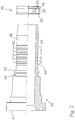
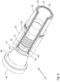
- FIGS. 1 to 5 an embodiment of the hose coupling 10 according to the invention is shown. It consists of a coupling element 40, a press socket 30 and a tear-off locking ring 50.
- a high-pressure hose 20 is connected to this hose coupling 10.
- This high-pressure hose 20 is provided with an inner and an outer plastic jacket 21, 23 which cover a metal insert 22.
- Such a high-pressure hose 20 can be used for very high pressures and high pulse loads.
- the end of the high-pressure hose 20 is peeled inside and outside, i.e. it has no outer plastic jacket 21 and no inner plastic jacket 23 in this front area of the hose coupling 10, which is referred to as securing area A, but consists exclusively of the metal insert 22.
- the high-pressure hose 20 has been freed from its outer plastic jacket 21.
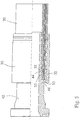
- the high-pressure hose 20 prepared in this way is, together with a press fitting 30 encompassing the high-pressure hose 20, onto the hose nipple 41 of the coupling element 40, as in FIG Fig. 4 indicated by the arrow, postponed.
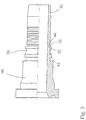
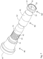
- the coupling element 40 is a known coupling element 40 for standard applications, see FIG Fig. 2 .
- the coupling element 40 can be fixed to a desired fitting, for example with a union nut (not shown).
- the coupling element 40 has a hose nipple 41.
- This has a structure in the form of ribs 42 and depressions 43 on its outer surface.
- the ribs 42 press into its inner jacket 23 when the high-pressure hose 20 is pushed on.
- the first depressions 44 of the depressions 43 provided on the outer surface, as seen from the front end 47, are used in this exemplary embodiment for positioning the tear-off protection ring 50. It is also possible that several depressions are used to fix the tear-off protection ring 50.
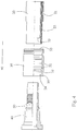
- the tear-off locking ring 50 shown has holding means 53 for its positioning on the hose nipple 41 on its inside 52.
- these holding means 53 consist of a radially inwardly directed circumferential rib, which as from Fig. 3 can be seen, when the pull-out locking ring 50 is pushed onto the hose nipple 41, it can be pressed into the first recess 44. This is possible because the anti-tear ring 50 is positioned when it is pushed onto the hose nipple 41 by resting against the shoulder 45 of the coupling element 40 in such a way that the holding means 53 are arranged opposite the first recess 44.
- the inside diameter of the anti-tear-off ring 50 is determined by the inside diameter of the rib serving as the holding means 53. This inner diameter is adapted to the outer diameter of the hose nipple 41 in such a way that the tear-off locking ring 50 can easily be pushed onto the hose nipple 41 until its front end rests on the shoulder 45, as in FIG Fig. 3 shown.
- the tear-off locking ring 50 shown also has a circumferential groove 55 on its outside 54. For larger hose couplings, tear-off safeguards with more than one circumferential groove can also be provided. Is the anti-tear ring 50, as in Fig.
- the coupling element 40 When pushed on, the coupling element 40 is comparable to a coupling element 40 with an integrally formed, ie molded-in, bulge for a pull-out protection.
- a circumferential groove 55 is provided adjacent to the shoulder 45, this circumferential groove 55 being delimited by two shoulders which protrude radially from the coupling element 40 and are dimensioned so large that they protrude significantly beyond the ribs 42 of the hose nipple 41.
- the pull-out protection ring 50 can be fixed on the hose nipple 41 by exerting slight radial pressure on the pull-out protection ring 50.
- a pre-fixing is not necessary to produce the fastening position of the hose coupling.
- the prepared high-pressure hose 20 is inserted into the press socket 30 and, together with the press socket 30, pushed onto the hose nipple 41, which is already provided with the anti-tear ring 50.
- This mounting position is in Fig. 5 shown.
- the high-pressure hose 20, together with the press socket 30, is pushed onto the coupling element 40 until an inwardly directed collar 35 is positioned at the front end 34 of the press socket 30 at the level of a circumferential groove 46 of the coupling element 40.
- the high-pressure hose 20 can be pushed up to this collar 35 of the press socket 30 and the peeled-free high-pressure hose 20, namely the metal insert 22, rests on the radially protruding shoulders of the tear-off locking ring 50, which delimit the circumferential groove 55.
- a first rib 32 of the press socket 30 is arranged opposite the circumferential groove 55.
- the press socket 30 can be seen better in its original form. Starting from the front end 34, where the inwardly directed collar 35 is provided, it has a structuring on the inside in the form of axially spaced radial ribs 31, 32.
- the first rib 32 is larger dimensioned rib, which is in the fastening position of the hose coupling 10 - see Fig. 1 - is located in security area A.
- the further ribs 31 are in the fastening position in the sealing area B.
- the ribs 31, 32 are preferably designed like teeth so that they can easily be pressed into the high-pressure hose 20 during radial pressing. It is of course also possible to provide the ribs 31, 32 in a spiral shape.
- the tear-off locking ring 50 is fixed at the same time on the hose nipple 41 by the holding means 53 engaging the first recess 44 on the hose nipple 41.
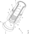
- FIGS. 6 to 10 a further embodiment of the hose coupling 10 'according to the invention is shown.
- the same reference numerals have been used for the same components.
- the same coupling element 40, the same press socket 30 and the same high-pressure hose 20 were used.
- a slotted ring is used as a tear-off locking ring 50 '.
- the first depressions 44 as seen from the front end 47, of the depressions 43 of the hose nipple 41 of the coupling element 40, which are provided on the outer surface, are used to position the tear-off locking ring 50 ′. It is also possible that several depressions are used to fix a slotted anti-tear ring Fig. 7
- the tear-off protection ring 50 'shown has holding means 53 on its inside 52 for its positioning on the hose nipple 41. In this case, these holding means 53 consist of a radially inwardly directed circumferential rib which, when the tear-off protection ring 50' is pushed onto the hose nipple 41, into the first recess 44 can be pressed in.
- a mounting sleeve 60 is used to push the anti-tear ring 50 'onto the hose nipple 41, which is shown in FIG Fig. 7 is shown.
- This mounting sleeve 60 has two areas 61, 62.
- the conical area 61 has its smallest diameter at the end of the mounting sleeve 60.
- the smallest diameter on the inside diameter of the relaxed anti-pull-out ring 50', as shown in FIG Fig. 7 shown is adjusted.
- the tear-off protection ring 50 ′ has a slot 57 and can therefore easily be pushed onto the area 61 of the mounting sleeve 60.
- the anti-tear ring 50' is expanded and reaches the second area 62 of the mounting sleeve 60.
- the second area 62 of the assembly sleeve is used to hold the anti-tear ring 50 'during assembly.
- the mounting sleeve 60 is pushed onto the hose nipple 41 together with the anti-tear ring 50 ′.
- the inner diameter of the mounting sleeve 60 is adapted to the outer diameter of the hose nipple 41.
- the mounting sleeve 60 can also have a stop on its inside, which prevents the mounting sleeve 60 from being pushed up to the shoulder 45 of the coupling element 40. In Fig. 8 the end position of such a mounting sleeve 60 is shown.
- the mounting sleeve 60 covers all the recesses 43 of the hose nipple 41 except for the first recess 44.
- the anti-tear ring 50 'held on the mounting sleeve 60 is then pushed forward, i.e.
- the anti-tear ring 50 ' is relaxed again, visible at the narrow slot 57.
- the inner diameter of the anti-tear ring 50' is adapted to the outer diameter of the hose nipple 41, in particular the inner diameter of the anti-tear ring 50 'in the area of the holding means 53 is adapted to the outer diameter of the Hose nipple 41 adapted in the region of the recess 44.
- the tear-off locking ring 50 ′ shown also has a circumferential groove 55 on its outside 54.
- tear-off safeguards with more than one circumferential groove can also be provided. Is the anti-tear ring 50 ', as in Fig. 9 shown, pushed onto the hose nipple 41, the prepared high-pressure hose 20 and the press socket 30 can be pushed onto the hose nipple 41 individually or together in a known manner. This situation is in Fig. 10 shown. A first rib 32 of the press socket 30 is arranged opposite the circumferential groove 55. To achieve the fastening position of the hose coupling 10 ', shown in FIG Fig.
- a pressure is exerted evenly radially on the press socket 30 in a special press, the ribs 31 engage in the Metal insert 22 of high pressure hose 20 and press high pressure hose 20 against hose nipple 41, which presses with its ribs 42 into inner jacket 23 of high pressure hose 20.
- the first rib 32 of the press socket 30 is simultaneously pressed into the circumferential groove 55 of the anti-tear ring 50 ', which results in a secure connection between the press socket 30, high-pressure hose 20 and hose nipple 41, namely a permanent metallic connection between hose nipple 41 with the metallic, the metal insert 22 and the rib 32 of the press socket 30.
- the collar 35 of the press socket 30 is simultaneously pressed into the circumferential groove 46 on the coupling element 40, which secures the press socket 30 on the coupling element 40.
- the mounting position is in Fig. 6 to see.
- the tear-off locking ring 50 ' was closed, the slot 57 has disappeared.
- the slot 57 must be adapted accordingly.
- a width of the slot 57 of 2.4 mm was selected for the relaxed tear-off locking ring 50 '.
- the slot 57 is preferably sized too large rather than too small.
- the slot 57 is axially aligned in the present exemplary embodiment, but other slot shapes and arrangements are also possible.
- the illustrated embodiments show that a hose coupling 10, 10 'can be used for the highest pressure applications and for pulse-like pressure peaks with a standard coupling without pull-out protection through the use of a retrofittable pull-out protection ring 50, 50' according to the invention.
- the tear-off locking ring 50, 50 ′ can be designed differently in accordance with the coupling element 40 used and the shape of the hose nipple 41.
- 10 ' different press sockets 30 are used, namely also press sockets, as they are in the European patent document EP 2 196 716 B1 are shown, in which the ribs 31, 32 are designed by wall deformations of the press socket, so that recesses are arranged opposite the radially inwardly directed projections on the outside.
Description
Die Erfindung betrifft eine Schlauchkupplung, insbesondere für Hochdruckschläuche, mit einem zur Aufnahme des Schlauches bestimmten Schlauchnippel, der auf seinem Außenumfang mehrere in Achsrichtung hintereinanderliegende und radial verlaufende Vertiefungen und/oder Erhöhungen trägt, mit einer den Schlauchnippel übergreifenden und den Schlauch festlegenden zylinderartigen Pressfassung, die an ihrem Innenmantel radial verlaufende Rippen aufweist sowie an ihrem einen Ende mit einem nach innen gerichteten radialen Steg versehen ist, der bei der Verpressung der Pressfassung in eine nutartige Aufnahme des Schlauchnippels eingreift.The invention relates to a hose coupling, in particular for high-pressure hoses, with a hose nipple intended to receive the hose, which on its outer circumference has a plurality of radially extending depressions and / or elevations lying one behind the other in the axial direction, with a cylinder-like press fitting that extends over the hose nipple and fixes the hose, which has radially extending ribs on its inner jacket and is provided at one end with an inwardly directed radial web which engages in a groove-like receptacle of the hose nipple when the press socket is pressed.
Derartige Schlauchkupplungen werden beispielsweise bei Hydraulikleitungen verwendet, bei denen es darauf ankommt, hohen Drücke des übertragenden Mediums standzuhalten, ohne dass dabei der Schlauch bzw. die Schlauchkupplung zerbricht. Ein solcher Hochdruckschlauch ist in der Regel mehrlagig und enthält in bekannter Weise eine Metalleinlage, die für Hochdruckanwendungen notwendig ist. Eine solche Schlauchkupplung ist beispielsweise in dem Dokument
Eine Verbesserung zeigt hier eine Schlauchkupplung gemäß
Aufgabe der vorliegenden Erfindung ist es, die bisherige Situation zu verbessern und mit weniger zu lagernden Teilen für unterschiedliche Nennweiten Standardschlauchkupplungen bzw. Schlauchkupplungen mit einer Ausreißsicherung zur Verfügung zu stellen.The object of the present invention is to improve the previous situation and to provide standard hose couplings or hose couplings with a pull-out protection with fewer parts to be stored for different nominal widths.
Diese Aufgabe wird mit einer Schlauchkupplung mit den Merkmalen des Anspruchs 1 gelöst, nämlich mit einer Schlauchkupplung bestehend aus einem Hochdruckschlauch, einem rohrartigen Kupplungselement mit einem Standard-Schlauchnippel, einer unter radialem Druck verformbaren Pressfassung sowie einem weiteren Bauteil, welches eine nachrüstbare Ausreißsicherung darstellt. Auf diese Weise wird eine Standardschlauchkupplung sowohl im normalen Hochdruckbereich als auch zusammen mit der montierten Ausreißsicherung für höchste Drücke und impulsartige Druckspitzen anwendbar. Die Erfindung reduziert die herzustellenden und zu lagernden Bauteile für Schlauchkupplungen unterschiedlicher Nennweiten und Anwendungsfälle, da ein Kupplungselement mit einem Standard-Schlauchnippel sowohl für Standardanwendungen als auch mit der nachrüstbaren Ausreißsicherung für höchste Drücke einsetzbar ist. So muss nur noch ein Kupplungselement für eine Nennweite zur Verfügung gestellt werden.This object is achieved with a hose coupling with the features of claim 1, namely with a hose coupling consisting of a high-pressure hose, a tubular coupling element with a standard hose nipple, a press-fit fitting that can be deformed under radial pressure and a further component which is a retrofittable tear-out device. In this way, a standard hose coupling can be used both in the normal high pressure range and together with the installed anti-tear device for highest pressures and impulse-like pressure peaks. The invention reduces the components to be produced and stored for hose couplings of different nominal sizes and applications, since a coupling element with a standard hose nipple can be used both for standard applications and with the retrofittable tear-off protection for the highest pressures. So only one coupling element has to be provided for a nominal width.
Bei der neuen nachrüstbaren Ausreißsicherung handelt es sich um einen nachrüstbaren, beispielsweise auf den Schlauchnippel aufschiebbaren und am Schlauchnippel fixierbaren metallischen Ausreißsicherungsring, welcher aus einem zylindrischen Abschnitt besteht. Dieser zylindrische Abschnitt kann aus einem geschlossenen Ring, aus einem offenen Ring, aus mehreren Ringschalenstücken oder einer Spiralfeder bestehen. An der Außenseite des zylindrischen Abschnitts ist eine ringförmige Umfangsnut eingeformt, die beim radialen Verpressen zur Aufnahme von Material der Metalleinlage des Schlauches dient und an der Schlauchkupplung gegenüberliegend zu einer ersten Rippe der Pressfassung abgeordnet ist, um eine formschlüssige Verbindung zwischen der Pressfassung, der Metalleinlage des Schlauches und der Ausreißsicherung zu ermöglichen.The new retrofittable anti-tear device is a metal anti-tear ring which can be retrofitted, for example, which can be pushed onto the hose nipple and fixed on the hose nipple, and which consists of a cylindrical section. This cylindrical section can consist of a closed ring, an open ring, several ring shell pieces or a spiral spring. On the outside of the cylindrical section, an annular circumferential groove is formed, which serves to accommodate material of the metal insert of the hose during radial pressing and is located on the hose coupling opposite a first rib of the press socket in order to establish a positive connection between the press socket, the metal insert of the To enable hose and the pull-out protection.
Damit sich der auf den Schlauchnippel aufgeschobene Ausreißsicherungsring beim radialen Verpressen nicht in Längsrichtung auf dem Schlauchnippel verschiebt, wird dieser Ausreißsicherungsring am Schlauchnippel positioniert und in seiner Lage fixiert. Hierfür werden Haltemittel, insbesondere formschlüssig und/oder kraftschlüssig wirkende Haltemittel, am Ausreißsicherungsring vorgesehen.So that the anti-tear ring pushed onto the hose nipple does not move in the longitudinal direction on the hose nipple during radial pressing, this anti-tear ring is positioned on the hose nipple and fixed in its position. For this purpose, holding means, in particular holding means acting positively and / or non-positively, are provided on the tear-off locking ring.
Bei einer ersten Ausführungsform sind für eine solche Positionierung Haltemittel am Ausreißsicherungsring vorgesehen, die vorzugsweise einstückig, d.h. integral, mit dem zylindrischen Abschnitt des Ausreißsicherungsrings ausgebildet sind. Diese Haltemittel werden bei einer bevorzugten Ausführungsform an der Innenseite des Ausreißsicherungsrings vorgesehen, um zur Positionierung mit entsprechenden Mitteln des Schlauchnippels zusammenwirken zu können. Ein Schlauchnippel ist am hinteren Ende des rohrartigen Kupplungselements vorgesehen. Am vorderen Ende ist das Kupplungselement an eine Armatur anschließbar. Der Schlauchnippel weist zur Aufnahme des Hochdruckschlauchs an seinem Außenumfang mehrere in Achsrichtung hintereinanderliegende radial verlaufende Vertiefungen und zwischen den Vertiefungen zum Hochdruckschlauch gerichtete rippenartige Erhöhungen aus. Für die Positionierung des Ausreißsicherungsrings wird eine am Schlauchnippel vorhandene Vertiefung und/oder Erhöhung genutzt, vorzugsweise ausgehend vom vorderen Ende des Kupplungselementes die erste Vertiefung am Schlauchnippel. Die vorgenannten Haltemittel des Ausreißsicherungsrings können ein oder mehrere radial nach innen gerichtete Vorsprünge oder Nuten umfassen. In einfachster Weise wird eine radial nach innen gerichtete umlaufende Rippe als Haltemittel am Ausreißsicherungsring vorgesehen. Besteht der zylindrische Abschnitt des Ausreißsicherungsrings aus einem geschlossenen Ring, so kann die als Haltemittel vorgesehene Rippe beim radialen Verpressen in die erste Vertiefung des Schlauchnippels umfangsseitig eingreifen. Die Positionierung und Festlegung dieses Ausreißsicherungsrings kann einerseits zusammen mit dem radialen Verpressen der Pressfassung vorgenommen werden. In dem Fall, wo ein Ausreißsicherungsring vormontiert am Schlauchnippel geliefert werden soll, kann dieser Ausreißsicherungsring andererseits auch vorab durch radiales Verpressen am Schlauchnippel fixiert werden.In a first embodiment, holding means are provided on the tear-off protection ring for such positioning, which means are preferably formed in one piece, ie integrally, with the cylindrical section of the tear-off protection ring. In a preferred embodiment, these holding means are provided on the inside of the tear-off locking ring in order to be able to interact with corresponding means of the hose nipple for positioning. A hose nipple is provided at the rear end of the tubular coupling element. At the front end, the coupling element can be connected to a fitting. The hose nipple points to Receiving the high-pressure hose on its outer circumference has a plurality of radially extending depressions lying one behind the other in the axial direction and rib-like elevations directed towards the high-pressure hose between the depressions. A recess and / or elevation present on the hose nipple is used for positioning the tear-off locking ring, preferably the first recess on the hose nipple starting from the front end of the coupling element. The aforementioned holding means of the tear-off locking ring can comprise one or more radially inwardly directed projections or grooves. In the simplest way, a radially inwardly directed circumferential rib is provided as a holding means on the anti-tear ring. If the cylindrical section of the anti-tear ring consists of a closed ring, the rib provided as a holding means can engage circumferentially in the first recess of the hose nipple during radial pressing. The positioning and fixing of this anti-tear ring can be carried out on the one hand together with the radial pressing of the press socket. In the case where a pull-out locking ring is to be delivered preassembled on the hose nipple, this pull-out locking ring can, on the other hand, also be fixed in advance by radial pressing on the hose nipple.
Bei einer weiteren Ausführungsform sind für eine Positionierung kraftschlüssig wirkende Haltemittel am Ausreißsicherungsring vorgesehen. Wird beispielsweise ein magnetisierter Ausreißsicherungsring auf den Schlauchnippel aufgeschoben und zwar bis er an die Schulter des Kupplungselements anschlägt, bleibt er aufgrund der magnetischen Anziehung an der metallischen Schulter anliegend fixiert.In a further embodiment, non-positively acting holding means are provided on the tear-off locking ring for positioning. For example, if a magnetized anti-tear ring is pushed onto the hose nipple until it hits the shoulder of the coupling element, it remains fixed against the metallic shoulder due to the magnetic attraction.
Bei einer weiteren Ausführungsform, wo der zylindrische Abschnitt des Ausreißsicherungsrings aus einem geschlitzten Ring besteht, können zur Positionierung und Festlegung des Ausreißsicherungsrings am Schlauchnippel des Kupplungselementes ebenfalls Haltemittel in Form von ein oder mehreren radial nach innen gerichtete Vorsprünge oder Nuten vorgesehen werden. Ein solcher geschlitzter Ring muss zur Montage jedoch nicht auf das Kupplungselement aufgepresst werden. Besteht der Ring aus einem elastischen Material, kann der Ring zum Aufschieben auf den Schlauchnippel aufgeweitet werden. Ist die gewünschte Position erreicht, kann sich der Ring wieder in seine Ursprungsform zurück bewegen und sich an einer oder mehreren vorgesehenen Vertiefungen und/oder Erhöhungen am Schlauchnippel verklemmen. Gleiches gilt für eine Spiralfeder.In a further embodiment, where the cylindrical section of the anti-tear ring consists of a slotted ring, retaining means in the form of one or more radially inwardly directed projections or grooves can also be provided for positioning and fixing the anti-tear ring on the hose nipple of the coupling element. On However, such a slotted ring does not have to be pressed onto the coupling element for assembly. If the ring is made of an elastic material, the ring can be expanded to slide onto the hose nipple. Once the desired position has been reached, the ring can move back into its original shape and jam in one or more provided depressions and / or elevations on the hose nipple. The same applies to a spiral spring.
Bei einer weiteren Ausführungsform wird der geschlitzte Ring ohne zusätzliche Haltemittel vorgesehen und in gleicher Weise, wie vorbeschrieben, am Schlauchnippel des Kupplungselementes montiert. Die Fixierung eines geschlitzten Ringes erfolgt vorzugsweise über eine form- und/ oder kraftschlüssige Verbindung.In a further embodiment, the slotted ring is provided without additional holding means and is mounted on the hose nipple of the coupling element in the same way as described above. A slotted ring is preferably fixed via a form-fitting and / or force-fitting connection.
Bei einer weiteren Ausführungsform besteht der zylindrische Abschnitt des Ausreißsicherungsrings aus mehreren Ringschalenstücken, vorzugsweise aus zwei Halbschalenstücken. Zur Positionierung und Festlegung der Ringschalenstücke des Ausreißsicherungsrings am Schlauchnippel des Kupplungselementes können diese durch eine stoffschlüssige Verbindung am Schlauchnippel fixiert werden. Dies kann eine Klebeverbindung oder auch eine Schweiß- oder Lötverbindung sein.In a further embodiment, the cylindrical section of the anti-tear ring consists of a plurality of annular shell pieces, preferably two half-shell pieces. To position and fix the ring shell pieces of the tear-off protection ring on the hose nipple of the coupling element, they can be fixed on the hose nipple by a material connection. This can be an adhesive connection or a welded or soldered connection.
Ein geschlossener Ring besteht aus einem Metallmaterial, vorzugsweise aus einer Stahllegierung und kann durch spanlose oder spanende Umformverfahren aus einem Rohrabschnitt hergestellt werden, beispielsweise durch Drehen, Tiefziehen oder Hydroformen.A closed ring consists of a metal material, preferably a steel alloy, and can be produced from a pipe section by non-cutting or cutting forming processes, for example by turning, deep drawing or hydroforming.
Ein geschlitzter Ring besteht aus einem elastischen Material, beispielsweise aus Metall, bevorzugt aus vergütetem Stahl, wie z.B. Federstahl. Er wird als Ring durch spanlose oder spanende Umformverfahren aus einem Rohrabschnitt hergestellt, beispielsweise durch Drehen, Tiefziehen oder Hydroformen, anschließend vergütet, so dass er seine elastischen Eigenschaften erhält und nachfolgend geschlitzt, beispielsweise durch Erodieren. Das Erodieren ermöglicht eine genaue Schlitzbreite im Ring vorzusehen. Ein solcher Ring kann auch aus einem anderen elastischen Material, wie beispielsweise hochfestem Kunststoff bestehen, vorzugsweise aus Polyetheretherketon (PEEK).A slotted ring consists of an elastic material, for example metal, preferably tempered steel, such as spring steel. It is produced as a ring from a pipe section by non-cutting or cutting forming processes, for example by turning, deep drawing or hydroforming, then tempered so that it retains its elastic properties and subsequently slotted, for example by erosion. The erosion enables an exact slot width to be provided in the ring. Such a ring can also consist of another elastic material, such as high-strength plastic, preferably of polyetheretherketone (PEEK).
Ringschalenstücke können aus Metall oder hochfestem Kunststoff bestehen.Ring shell pieces can consist of metal or high-strength plastic.
Der Ausreißsicherungsring besitzt an der Außenseite seines zylindrischen Abschnitts eine Umfangsnut. Bei einer weiteren Ausführungsform der Ausreißsicherung wird am Ausreißsicherungsring mehr als eine Umfangsnut vorgesehen.The anti-tear ring has a circumferential groove on the outside of its cylindrical section. In a further embodiment of the anti-tear device, more than one circumferential groove is provided on the anti-tear device.
Die Befestigungslage der neuen Schlauchkupplung mit Ausreißsicherungsring wird in gleicher Weise wie bei bekannten Schlauchkupplungen erzielt. Der Hochdruckschlauch, bei dem zwischen zwei Kunststoffmäntel eine Metalleinlage aus einem Drahtgeflecht oder aus mindestens einer Drahtspiralenwicklung angeordnet ist, wird an einem Ende von seinem Innen- und Außenmantel aus Kunststoff befreit und dieses Ende des Schlauches wird in die Pressfassung eingeführt und zusammen mit der Pressfassung auf den Schlauchnippel mit dem vormontierten Ausreißsicherungsring aufgeschoben. Schließlich wird durch äußeren radialen Druck die Pressfassung radial verpresst. Bei einem geschlossenen zylindrischen Abschnitt als Ausreißsicherungsring sind Haltemittel vorhanden. Bereits im Anfangsstadium des Pressvorgangs wird mittels der Haltemittel des Ausreißsicherungsrings eine Fixierung dieses Ausreißsicherungsrings am Schlauchnippel erzielt und damit der Ausreißsicherungsring am Schlauchnippel in seiner vorgesehenen Lage positioniert. Bei anderen Ausführungsformen des Ausreißsicherungsrings sind diese bereits vor dem Verpressen am Schlauchnippel fixiert. Beim radialen Verpressen wird die Metalleinlage des Schlauchs durch eine Rippe der Pressfassung in die Umfangsnut der Ausreißsicherung gedrückt und es kommt nachfolgend zu einer kraft- und formschlüssigen Verbindung zwischen der metallischen Pressfassung, der Metalleinlage des Schlauchs, der gegebenenfalls metallischen Ausreißsicherung und dem metallischem Schlauchnippel. Die metallischen Bauteile der Verbindung können durch die Presskraft metallisch verschweißen. Dies führt zu einer sicheren und zugfesten Verbindung des Schlauches an der Schlauchkupplung.The fastening position of the new hose coupling with a pull-out locking ring is achieved in the same way as with known hose couplings. The high-pressure hose, in which a metal insert made of a wire mesh or at least one wire spiral winding is arranged between two plastic jackets, is freed from its inner and outer plastic jacket at one end and this end of the hose is inserted into the press socket and open together with the press socket the hose nipple with the pre-assembled anti-tear ring is pushed on. Finally, the press socket is pressed radially by external radial pressure. In the case of a closed cylindrical section as a tear-off locking ring, retaining means are present. Already in the initial stage of the pressing process, by means of the holding means of the anti-tear ring, this anti-tear ring is fixed on the hose nipple and the anti-tear ring is thus positioned on the hose nipple in its intended position. In other embodiments of the anti-tear ring, these are already fixed to the hose nipple before pressing. During radial pressing, the metal insert of the hose is pressed by a rib of the press fitting into the circumferential groove of the anti-tear device and a non-positive and positive connection then occurs between the metallic press fitting, the metal insert of the hose, which may be metallic pull-out protection and the metallic hose nipple. The metallic components of the connection can weld together using the pressing force. This leads to a secure and tensile connection of the hose to the hose coupling.
Der Bereich der Schlauchkupplung, wo am Schlauchnippel der Ausreißsicherungsring vorgesehen ist, wird nachfolgend Sicherungsbereich genannt. Der Anschlussbereich für den Hochdruckschlauch in der Schlauchkupplung umfasst zwei Bereiche, nämlich den vorbeschriebenen vorderen Sicherungsbereich mit der Ausreißsicherung und einen sich in Axialrichtung anschließenden Dichtbereich. Im Dichtbereich wird vom Hochdruckschlauch vorzugsweise der äußere Kunststoffmantel abgeschält, so dass beim radialen Verpressen die Rippen der Pressfassung in die Metalleinlage eingreifen und die Erhöhung am Schlauchnippel sich in den Innenmantel des Schlauches einpressen können. Die am Innenmantel der Pressfassung vorgesehenen radial nach innen gerichteten Rippen können unterschiedlich ausgebildet sein, vorzugsweise ist die Rippe oder sind die Rippen im Sicherungsbereich größer dimensioniert als die Rippen im Dichtbereich.The area of the hose coupling where the anti-tear ring is provided on the hose nipple is referred to below as the safety area. The connection area for the high-pressure hose in the hose coupling comprises two areas, namely the above-described front securing area with the tear-off protection and a sealing area adjoining it in the axial direction. In the sealing area, the outer plastic jacket is preferably peeled off from the high-pressure hose, so that the ribs of the press socket engage in the metal insert during radial pressing and the elevation on the hose nipple can be pressed into the inner jacket of the hose. The radially inwardly directed ribs provided on the inner jacket of the press socket can be designed differently; the rib or ribs in the securing area are preferably larger than the ribs in the sealing area.
In der Zeichnung ist der erfindungsgemäße Gegenstand in zwei Ausführungsbeispielen dargelegt und zwar zeigt:
- Fig. 1
- eine erfindungsgemäße Schlauchkupplung in Befestigungslage,
- Fig. 2
- das Kupplungselement von
Fig. 1 und den separaten Ausreißsicherungsring, - Fig. 3
- das Kupplungselement von
Fig. 1 mit aufgeschobenem Ausreißsicherungsring, - Fig. 4
- die Schlauchkupplung von
Fig. 1 vor der Montage, - Fig. 5
- die montierte Schlauchkupplung von
Fig. 1 vor dem Verpressen, - Fig. 6
- eine weitere erfindungsgemäße Schlauchkupplung in Befestigungslage,
- Fig. 7
- das Kupplungselement von
Fig. 6 vor der Montage, - Fig.
- 8 das Kupplungselement von
Fig. 6 während der Montage, - Fig. 9
- das Kupplungselement von
Fig. 6 mit aufgeschobenem Ausreißsicherungsring, - Fig. 10
- die montierte Schlauchkupplung von
Fig. 6 vor dem Verpressen.
- Fig. 1
- a hose coupling according to the invention in the fastening position,
- Fig. 2
- the coupling element of
Fig. 1 and the separate pull-out locking ring, - Fig. 3
- the coupling element of
Fig. 1 with attached pull-out locking ring, - Fig. 4
- the hose coupling of
Fig. 1 before assembly, - Fig. 5
- the assembled hose coupling from
Fig. 1 before pressing, - Fig. 6
- another hose coupling according to the invention in the fastening position,
- Fig. 7
- the coupling element of
Fig. 6 before assembly, - Fig.
- 8 the coupling element of
Fig. 6 during assembly, - Fig. 9
- the coupling element of
Fig. 6 with attached pull-out locking ring, - Fig. 10
- the assembled hose coupling from
Fig. 6 before pressing.
In den
Bei dem Kupplungselement 40 handelt es sich um ein bekanntes Kupplungselement 40 für Standardanwendungen, siehe
Wenn man ein solches Kupplungselement 40 mit Ausreißsicherung 50 vormontiert liefert, kann durch geringfügige radiale Druckausübung auf den Ausreißsicherungsring 50 dieser am Schlauchnippel 41 fixiert werden. Zur Herstellung der Befestigungslage der Schlauchkupplung ist eine solche Vorfixierung jedoch nicht notwendig.If such a
Zur Erzielung der Befestigungslage der Schlauchkupplung 10 wird, wie in
Wird nun die in
In den
Auch in diesem Ausführungsbeispiel wird zur Positionierung des Ausreißsicherungsrings 50' die vom vorderen Ende 47 aus gesehen erste Vertiefungen 44 der an der äußeren Oberfläche vorgesehenen Vertiefungen 43 des Schlauchnippels 41 des Kupplungselementes 40 verwendet. Es ist auch möglich, dass mehrere Vertiefungen zur Fixierung eines geschlitzten Ausreißsicherungsrings herangezogen werden Der in
Der Schlitz 57 ist im vorliegenden Ausführungsbeispiel axial ausgerichtet, es sind jedoch auch andere Schlitzformen und Anordnungen möglich.The
Die dargestellten Ausführungsbeispiele zeigen, dass mit einer Standardkupplung ohne Ausreißsicherung durch die Verwendung eines erfindungsgemäßen nachrüstbaren Ausreißsicherungsrings 50, 50' eine Schlauchkupplung 10, 10' für höchste Druckanwendungen und für impulsartige Druckspitzen verwendbar ist.The illustrated embodiments show that a
Die Erfindung ist nicht auf die gezeigten Ausführungsbeispiele beschränkt. So kann der Ausreißsicherungsring 50, 50' entsprechend dem verwendeten Kupplungselement 40 und der Gestalt des Schlauchnippels 41 unterschiedlich gestaltet sein. Darüber hinaus können für eine Schlauchkupplung 10, 10' unterschiedliche Pressfassungen 30 verwendet werden, nämlich auch Pressfassungen, wie sie im europäischen Patentdokument
- 10. 10'10. 10 '
- SchlauchkupplungHose coupling
- 2020th
- HochdruckschlauchHigh pressure hose
- 2121
- KunststoffmantelPlastic jacket
- 2222nd
- MetalleinlageMetal insert
- 2323
- KunststoffmantelPlastic jacket
- 3030th
- PressfassungPress version
- 3131
- RippenRibs
- 3232
- erste Rippefirst rib
- 3333
- hinteres Enderear end
- 3434
- vorderes Endefront end
- 3535
- Kragencollar
- 4040
- KupplungselementCoupling element
- 4141
- SchlauchnippelHose nipple
- 4242
- RippenRibs
- 4343
- VertiefungenIndentations
- 4444
- erste Vertiefungfirst deepening
- 4545
- Schultershoulder
- 4646
- UmfangsnutCircumferential groove
- 4747
- vorderes Endefront end
- 50, 50'50, 50 '
- AusreißsicherungsringAnti-tear ring
- 5151
- zylindrischer Abschnittcylindrical section
- 5252
- Innenseiteinside
- 5353
- HaltemittelHolding means
- 5454
- AußenseiteOutside
- 5555
- UmfangsnutCircumferential groove
- 5656
- AnschlagkanteStop edge
- 5757
- Schlitz bei entspanntem Ausreißsicherungsring 50'Slot when the pull-out locking ring is relaxed 50 '
- 57'57 '
- Schlitz bei aufgeweitetem Ausreißsicherungsring 50'Slot with expanded anti-tear ring 50 '
- 6060
- MontagehülseAssembly sleeve
- 6161
- Bereich von 60Range from 60
- 6262
- Bereich von 60Range from 60
- AA.
- SicherungsbereichSecurity area
- BB.
- DichtbereichSealing area
Claims (15)
- Hose coupling (10), in particular for high pressure hydraulic lines or maximum pressure hydraulic lines,- with a high pressure hose (20), in which a metal insert (22) made of a wire mesh or of at least one wire spiral winding is arranged between two plastic sheaths (21, 23),- with a tubular coupling element (40), which can be connected at the front end (47) to a fitting and which has a hose nipple (41) at the other end for receiving the high pressure hose (20), which hose nipple (41) at its outer circumference has several radially extending recesses (43) located one behind the other in the axial direction and ribs (42) directed to the high pressure hose (20) between the recesses (43),- wherein the connecting region for the high pressure hose (20) in the hose coupling (10) comprises two areas, namely a front securing area (A) with a tear-off protection and a sealing area (B) adjacent in the axial direction,- with a press socket (30) deformable under radial pressure, wherein the press socket (30) at its inner surface has ribs (31, 32) directed to the high pressure hose (20), wherein at least one rib (32) of larger dimensions is provided in the securing area (A),- wherein in the securing area (A) the metal insert (22) freed from the plastic sheaths (21, 23) is pressed between the hose nipple (41) and press socket (30),characterised in that- for the tear-off protection in the securing area (A) a tear-off protection ring (50, 50') is provided which can be pushed onto the hose nipple (41) and fixed to the hose nipple (41), which consists of a cylindrical section before the pressing and has at least one circumferential groove (55) on its outer side (54),- wherein in the assembly position of the hose coupling (10), the circumferential groove (55) is directed radially outwards and is arranged at the press socket (30) opposite to the rib (32) of larger dimensions and serves to receive material of the metal insert (22) of the high pressure hose (20) during radial pressing,- so that in the mounting position, there is a force- and form-fitting connection between the rib (32) of the press socket (30), the metal insert (22) of the high pressure hose (20), the tear-off protection ring (50, 50') in the area of the circumferential groove (55) and the hose nipple (41).
- Hose coupling according to claim 1, characterised in that the tear-off protection ring (50, 50') consists of metal and there is a non-detachable metallic connection between the rib (32) of the press socket (30), the metal insert (22) of the high pressure hose (20), the tear-off protection ring (50, 50') and the hose nipple (41).
- Hose coupling according to claim 1 or 2, characterised in that the tear-off protection ring (50, 50') consists of a cylindrical section (51), which is provided with holding means (53) for the positioning at and/or securing to the hose nipple (41), wherein the holding means (53) are preferably integrally formed with the cylindrical section (51).
- Hose coupling according to claim 3, characterised in that the holding means (53) are provided on the inside (52) of the tear-off protection ring (50) in order to be able to engage in a recess (43) of the hose nipple (41) for fixing to the hose nipple (41).
- Hose coupling according to claim 4, characterised in that the holding means (53) comprise one or several projections directed radially inwards, preferably a circumferential rib directed radially inwards.
- Hose coupling according to claim 3, characterised in that a magnetisation of the tear-off protection ring (50) is provided as a holding means.
- Hose coupling according to one of claims 1 to 6, characterised in that the tear-off protection ring (50, 50') in the mounted state abuts against a shoulder (45) of the coupling element (40).
- Hose coupling according to one of claims 1 to 7, characterised in that the tear-off protection ring (50) consists of a circumferentially closed cylindrical section (51) and is pre-mounted on the hose nipple (41) by radial pressing.
- Hose coupling according to one of claims 1 to 7, characterised in that the tear-off protection ring (50') consists of an elastic cylindrical section, preferably of a cylindrical section with a slot (57, 57').
- Hose coupling according to one of claims 1 to 7, characterised in that the tear-off protection ring consists of a cylindrical section, which is composed of several annular shell pieces, preferably of two half-shells.
- Hose coupling according to claim 1, characterised in that the tear-off protection ring (50, 50') is made of high-strength plastic.
- Hose coupling according to one of claims 1 to 11, characterised in that in the sealing area (B), the high pressure hose (20) freed from the outer plastic sheath (21) is pressed between hose nipple (41) and press socket (30).
- Hose coupling according to one of claims 1 to 12, characterised in that the press socket (30) at the front end has a collar (35) directed radially inwards, which engages in a circumferential groove (46) of the coupling element (40).
- Hose coupling according to one of claims 1 to 13, characterised in that the press socket (30) is extended with its rear end beyond the sealing area (B) and comprises with this extended area the entire hydraulic hose (20) with its two plastic sheaths (21, 23) and the metal insert (22).
- Hose coupling according to one of claims 1 to 14, characterised in that, during assembly, the tear-off protection ring (50, 50') is pre-positioned on the hose nipple (41) and the press socket (30) surrounds the hose nipple (41) including the tear-off protection ring (50, 50') with the hydraulic hose (20) slid thereon and, during fixing, the press socket (30) with the ribs (31, 32) engages with the hydraulic hose (20), wherein the hose coupling (10) can be transferred from assembly to fixing by applying an external radial pressure onto the press socket (30).
Priority Applications (1)
| Application Number | Priority Date | Filing Date | Title |
|---|---|---|---|
| PL12000300T PL2503206T3 (en) | 2011-03-23 | 2012-01-19 | Hose coupling |
Applications Claiming Priority (2)
| Application Number | Priority Date | Filing Date | Title |
|---|---|---|---|
| DE202011004259U DE202011004259U1 (en) | 2011-03-23 | 2011-03-23 | hose coupling |
| DE202011103897U DE202011103897U1 (en) | 2011-03-23 | 2011-08-01 | hose coupling |
Publications (2)
| Publication Number | Publication Date |
|---|---|
| EP2503206A1 EP2503206A1 (en) | 2012-09-26 |
| EP2503206B1 true EP2503206B1 (en) | 2021-03-10 |
Family
ID=44311601
Family Applications (1)
| Application Number | Title | Priority Date | Filing Date |
|---|---|---|---|
| EP12000300.9A Active EP2503206B1 (en) | 2011-03-23 | 2012-01-19 | Hose coupling |
Country Status (4)
| Country | Link |
|---|---|
| EP (1) | EP2503206B1 (en) |
| DE (2) | DE202011004259U1 (en) |
| ES (1) | ES2873027T3 (en) |
| PL (1) | PL2503206T3 (en) |
Families Citing this family (5)
| Publication number | Priority date | Publication date | Assignee | Title |
|---|---|---|---|---|
| DE102011052852A1 (en) | 2011-08-19 | 2013-02-21 | Gustav Klauke Gmbh | pressing device |
| DE202011051339U1 (en) | 2011-09-16 | 2011-10-20 | Dipl.-Ing. H. Schulz Hds Hydraulik Gmbh & Co. Kg | Hose coupling for hydraulic hose lines |
| DE202013105869U1 (en) | 2013-12-20 | 2015-03-24 | Dipl.-Ing. H. Schulz Hds Hydraulik Gmbh & Co. Kg | Hose coupling for hydraulic hose lines with circumferential seal |
| CN110440072A (en) * | 2019-07-29 | 2019-11-12 | 江苏恒力化纤股份有限公司 | A kind of self-locking fast plug |
| DE102022204220A1 (en) * | 2022-04-29 | 2023-11-02 | Contitech Techno-Chemie Gmbh | Fluid line device |
Family Cites Families (6)
| Publication number | Priority date | Publication date | Assignee | Title |
|---|---|---|---|---|
| DE1164769B (en) * | 1954-10-04 | 1964-03-05 | Resistoflex Corp | Method for attaching hose couplings to hoses |
| FR1375466A (en) * | 1963-11-22 | 1964-10-16 | William Warne & Co Ltd | Assembly device for flexible hoses |
| US4924436A (en) | 1987-06-22 | 1990-05-08 | Energy Conversion Devices, Inc. | Data storage device having a phase change memory medium reversible by direct overwrite and method of direct overwrite |
| GB9307271D0 (en) * | 1993-04-07 | 1993-06-02 | Btr Plc | Improvements in and relating to a hose assembly |
| DE20106932U1 (en) | 2001-04-20 | 2001-08-02 | Voswinkel Kg | Hose fitting |
| ATE496251T1 (en) | 2008-12-11 | 2011-02-15 | Voswinkel Kg | HOSE COUPLING |
-
2011
- 2011-03-23 DE DE202011004259U patent/DE202011004259U1/en not_active Expired - Lifetime
- 2011-08-01 DE DE202011103897U patent/DE202011103897U1/en not_active Expired - Lifetime
-
2012
- 2012-01-19 ES ES12000300T patent/ES2873027T3/en active Active
- 2012-01-19 PL PL12000300T patent/PL2503206T3/en unknown
- 2012-01-19 EP EP12000300.9A patent/EP2503206B1/en active Active
Non-Patent Citations (1)
| Title |
|---|
| None * |
Also Published As
| Publication number | Publication date |
|---|---|
| EP2503206A1 (en) | 2012-09-26 |
| PL2503206T3 (en) | 2021-10-04 |
| DE202011004259U1 (en) | 2011-05-19 |
| ES2873027T3 (en) | 2021-11-03 |
| DE202011103897U1 (en) | 2011-10-19 |
Similar Documents
| Publication | Publication Date | Title |
|---|---|---|
| EP1959181B1 (en) | Fitting and connection assembly with a fitting | |
| EP1456574B1 (en) | Connection piece for fluid lines and device embodied thereas | |
| EP1653142B1 (en) | Press-fitting | |
| EP1790896B1 (en) | Press fitting for a pipe | |
| EP1924799B1 (en) | Connector piece for an end of a round in particular tubular object | |
| EP2503206B1 (en) | Hose coupling | |
| EP0925467B1 (en) | Flexible hose sleeve | |
| DE102007025931B3 (en) | Clamp fitting for a pipe | |
| DE10065225B4 (en) | joint assembly | |
| EP1740873B1 (en) | Hose coupling | |
| DE112012002695B4 (en) | Hose coupling, especially for hydraulic high-pressure lines of a release system | |
| WO2011128207A1 (en) | Spreading device, connection and system | |
| EP1267113B1 (en) | Connection member | |
| DE102014100012A1 (en) | Hose coupling for hydraulic hose lines with circumferential seal | |
| DE202007007827U1 (en) | Clamp fitting for a pipe | |
| EP1326045B1 (en) | Connector for at least one pipe part and method for making a connection with such a connector | |
| EP2196716B1 (en) | Hose coupling | |
| EP1564472B1 (en) | Hose coupling | |
| WO2008000358A1 (en) | Connecting fitting | |
| EP1743744A2 (en) | Device for replacement of a ball joint of a motor vehicle axle | |
| EP2038573B1 (en) | Pipe connection | |
| DE19852861C1 (en) | Pipe press connection | |
| EP1775508A2 (en) | Coupling arrangement for pipes | |
| EP3845791B1 (en) | Fitting | |
| DE202008016440U1 (en) | hose coupling |
Legal Events
| Date | Code | Title | Description |
|---|---|---|---|
| PUAI | Public reference made under article 153(3) epc to a published international application that has entered the european phase |
Free format text: ORIGINAL CODE: 0009012 |
|
| AK | Designated contracting states |
Kind code of ref document: A1 Designated state(s): AL AT BE BG CH CY CZ DE DK EE ES FI FR GB GR HR HU IE IS IT LI LT LU LV MC MK MT NL NO PL PT RO RS SE SI SK SM TR |
|
| AX | Request for extension of the european patent |
Extension state: BA ME |
|
| 17P | Request for examination filed |
Effective date: 20130321 |
|
| RAP1 | Party data changed (applicant data changed or rights of an application transferred) |
Owner name: U.M. GEWERBEIMMOBILIEN GMBH & CO. KG |
|
| STAA | Information on the status of an ep patent application or granted ep patent |
Free format text: STATUS: EXAMINATION IS IN PROGRESS |
|
| 17Q | First examination report despatched |
Effective date: 20170915 |
|
| GRAP | Despatch of communication of intention to grant a patent |
Free format text: ORIGINAL CODE: EPIDOSNIGR1 |
|
| STAA | Information on the status of an ep patent application or granted ep patent |
Free format text: STATUS: GRANT OF PATENT IS INTENDED |
|
| INTG | Intention to grant announced |
Effective date: 20200923 |
|
| GRAJ | Information related to disapproval of communication of intention to grant by the applicant or resumption of examination proceedings by the epo deleted |
Free format text: ORIGINAL CODE: EPIDOSDIGR1 |
|
| STAA | Information on the status of an ep patent application or granted ep patent |
Free format text: STATUS: EXAMINATION IS IN PROGRESS |
|
| INTC | Intention to grant announced (deleted) | ||
| GRAS | Grant fee paid |
Free format text: ORIGINAL CODE: EPIDOSNIGR3 |
|
| STAA | Information on the status of an ep patent application or granted ep patent |
Free format text: STATUS: GRANT OF PATENT IS INTENDED |
|
| GRAP | Despatch of communication of intention to grant a patent |
Free format text: ORIGINAL CODE: EPIDOSNIGR1 |
|
| STAA | Information on the status of an ep patent application or granted ep patent |
Free format text: STATUS: GRANT OF PATENT IS INTENDED |
|
| GRAA | (expected) grant |
Free format text: ORIGINAL CODE: 0009210 |
|
| STAA | Information on the status of an ep patent application or granted ep patent |
Free format text: STATUS: THE PATENT HAS BEEN GRANTED |
|
| INTG | Intention to grant announced |
Effective date: 20210129 |
|
| AK | Designated contracting states |
Kind code of ref document: B1 Designated state(s): AL AT BE BG CH CY CZ DE DK EE ES FI FR GB GR HR HU IE IS IT LI LT LU LV MC MK MT NL NO PL PT RO RS SE SI SK SM TR |
|
| REG | Reference to a national code |
Ref country code: GB Ref legal event code: FG4D Free format text: NOT ENGLISH |
|
| REG | Reference to a national code |
Ref country code: CH Ref legal event code: EP Ref country code: AT Ref legal event code: REF Ref document number: 1370182 Country of ref document: AT Kind code of ref document: T Effective date: 20210315 |
|
| REG | Reference to a national code |
Ref country code: IE Ref legal event code: FG4D Free format text: LANGUAGE OF EP DOCUMENT: GERMAN |
|
| REG | Reference to a national code |
Ref country code: DE Ref legal event code: R096 Ref document number: 502012016655 Country of ref document: DE |
|
| REG | Reference to a national code |
Ref country code: NL Ref legal event code: FP |
|
| REG | Reference to a national code |
Ref country code: LT Ref legal event code: MG9D |
|
| PG25 | Lapsed in a contracting state [announced via postgrant information from national office to epo] |
Ref country code: NO Free format text: LAPSE BECAUSE OF FAILURE TO SUBMIT A TRANSLATION OF THE DESCRIPTION OR TO PAY THE FEE WITHIN THE PRESCRIBED TIME-LIMIT Effective date: 20210610 Ref country code: BG Free format text: LAPSE BECAUSE OF FAILURE TO SUBMIT A TRANSLATION OF THE DESCRIPTION OR TO PAY THE FEE WITHIN THE PRESCRIBED TIME-LIMIT Effective date: 20210610 Ref country code: LT Free format text: LAPSE BECAUSE OF FAILURE TO SUBMIT A TRANSLATION OF THE DESCRIPTION OR TO PAY THE FEE WITHIN THE PRESCRIBED TIME-LIMIT Effective date: 20210310 Ref country code: HR Free format text: LAPSE BECAUSE OF FAILURE TO SUBMIT A TRANSLATION OF THE DESCRIPTION OR TO PAY THE FEE WITHIN THE PRESCRIBED TIME-LIMIT Effective date: 20210310 Ref country code: FI Free format text: LAPSE BECAUSE OF FAILURE TO SUBMIT A TRANSLATION OF THE DESCRIPTION OR TO PAY THE FEE WITHIN THE PRESCRIBED TIME-LIMIT Effective date: 20210310 Ref country code: GR Free format text: LAPSE BECAUSE OF FAILURE TO SUBMIT A TRANSLATION OF THE DESCRIPTION OR TO PAY THE FEE WITHIN THE PRESCRIBED TIME-LIMIT Effective date: 20210611 |
|
| PG25 | Lapsed in a contracting state [announced via postgrant information from national office to epo] |
Ref country code: SE Free format text: LAPSE BECAUSE OF FAILURE TO SUBMIT A TRANSLATION OF THE DESCRIPTION OR TO PAY THE FEE WITHIN THE PRESCRIBED TIME-LIMIT Effective date: 20210310 Ref country code: RS Free format text: LAPSE BECAUSE OF FAILURE TO SUBMIT A TRANSLATION OF THE DESCRIPTION OR TO PAY THE FEE WITHIN THE PRESCRIBED TIME-LIMIT Effective date: 20210310 Ref country code: LV Free format text: LAPSE BECAUSE OF FAILURE TO SUBMIT A TRANSLATION OF THE DESCRIPTION OR TO PAY THE FEE WITHIN THE PRESCRIBED TIME-LIMIT Effective date: 20210310 |
|
| PG25 | Lapsed in a contracting state [announced via postgrant information from national office to epo] |
Ref country code: EE Free format text: LAPSE BECAUSE OF FAILURE TO SUBMIT A TRANSLATION OF THE DESCRIPTION OR TO PAY THE FEE WITHIN THE PRESCRIBED TIME-LIMIT Effective date: 20210310 Ref country code: CZ Free format text: LAPSE BECAUSE OF FAILURE TO SUBMIT A TRANSLATION OF THE DESCRIPTION OR TO PAY THE FEE WITHIN THE PRESCRIBED TIME-LIMIT Effective date: 20210310 Ref country code: SM Free format text: LAPSE BECAUSE OF FAILURE TO SUBMIT A TRANSLATION OF THE DESCRIPTION OR TO PAY THE FEE WITHIN THE PRESCRIBED TIME-LIMIT Effective date: 20210310 |
|
| REG | Reference to a national code |
Ref country code: ES Ref legal event code: FG2A Ref document number: 2873027 Country of ref document: ES Kind code of ref document: T3 Effective date: 20211103 |
|
| PG25 | Lapsed in a contracting state [announced via postgrant information from national office to epo] |
Ref country code: RO Free format text: LAPSE BECAUSE OF FAILURE TO SUBMIT A TRANSLATION OF THE DESCRIPTION OR TO PAY THE FEE WITHIN THE PRESCRIBED TIME-LIMIT Effective date: 20210310 Ref country code: IS Free format text: LAPSE BECAUSE OF FAILURE TO SUBMIT A TRANSLATION OF THE DESCRIPTION OR TO PAY THE FEE WITHIN THE PRESCRIBED TIME-LIMIT Effective date: 20210710 Ref country code: SK Free format text: LAPSE BECAUSE OF FAILURE TO SUBMIT A TRANSLATION OF THE DESCRIPTION OR TO PAY THE FEE WITHIN THE PRESCRIBED TIME-LIMIT Effective date: 20210310 Ref country code: PT Free format text: LAPSE BECAUSE OF FAILURE TO SUBMIT A TRANSLATION OF THE DESCRIPTION OR TO PAY THE FEE WITHIN THE PRESCRIBED TIME-LIMIT Effective date: 20210712 |
|
| REG | Reference to a national code |
Ref country code: DE Ref legal event code: R097 Ref document number: 502012016655 Country of ref document: DE |
|
| PLBE | No opposition filed within time limit |
Free format text: ORIGINAL CODE: 0009261 |
|
| STAA | Information on the status of an ep patent application or granted ep patent |
Free format text: STATUS: NO OPPOSITION FILED WITHIN TIME LIMIT |
|
| PG25 | Lapsed in a contracting state [announced via postgrant information from national office to epo] |
Ref country code: DK Free format text: LAPSE BECAUSE OF FAILURE TO SUBMIT A TRANSLATION OF THE DESCRIPTION OR TO PAY THE FEE WITHIN THE PRESCRIBED TIME-LIMIT Effective date: 20210310 Ref country code: AL Free format text: LAPSE BECAUSE OF FAILURE TO SUBMIT A TRANSLATION OF THE DESCRIPTION OR TO PAY THE FEE WITHIN THE PRESCRIBED TIME-LIMIT Effective date: 20210310 |
|
| 26N | No opposition filed |
Effective date: 20211213 |
|
| PG25 | Lapsed in a contracting state [announced via postgrant information from national office to epo] |
Ref country code: SI Free format text: LAPSE BECAUSE OF FAILURE TO SUBMIT A TRANSLATION OF THE DESCRIPTION OR TO PAY THE FEE WITHIN THE PRESCRIBED TIME-LIMIT Effective date: 20210310 |
|
| PG25 | Lapsed in a contracting state [announced via postgrant information from national office to epo] |
Ref country code: IS Free format text: LAPSE BECAUSE OF FAILURE TO SUBMIT A TRANSLATION OF THE DESCRIPTION OR TO PAY THE FEE WITHIN THE PRESCRIBED TIME-LIMIT Effective date: 20210710 |
|
| PG25 | Lapsed in a contracting state [announced via postgrant information from national office to epo] |
Ref country code: MC Free format text: LAPSE BECAUSE OF FAILURE TO SUBMIT A TRANSLATION OF THE DESCRIPTION OR TO PAY THE FEE WITHIN THE PRESCRIBED TIME-LIMIT Effective date: 20210310 |
|
| REG | Reference to a national code |
Ref country code: BE Ref legal event code: MM Effective date: 20220131 |
|
| PG25 | Lapsed in a contracting state [announced via postgrant information from national office to epo] |
Ref country code: LU Free format text: LAPSE BECAUSE OF NON-PAYMENT OF DUE FEES Effective date: 20220119 |
|
| PG25 | Lapsed in a contracting state [announced via postgrant information from national office to epo] |
Ref country code: BE Free format text: LAPSE BECAUSE OF NON-PAYMENT OF DUE FEES Effective date: 20220131 |
|
| PGFP | Annual fee paid to national office [announced via postgrant information from national office to epo] |
Ref country code: IE Payment date: 20230119 Year of fee payment: 12 Ref country code: FR Payment date: 20230123 Year of fee payment: 12 Ref country code: ES Payment date: 20230216 Year of fee payment: 12 Ref country code: CH Payment date: 20230130 Year of fee payment: 12 Ref country code: AT Payment date: 20230118 Year of fee payment: 12 |
|
| PGFP | Annual fee paid to national office [announced via postgrant information from national office to epo] |
Ref country code: PL Payment date: 20230112 Year of fee payment: 12 Ref country code: IT Payment date: 20230131 Year of fee payment: 12 Ref country code: GB Payment date: 20230124 Year of fee payment: 12 Ref country code: DE Payment date: 20230119 Year of fee payment: 12 |
|
| P01 | Opt-out of the competence of the unified patent court (upc) registered |
Effective date: 20230513 |
|
| PGFP | Annual fee paid to national office [announced via postgrant information from national office to epo] |
Ref country code: NL Payment date: 20230124 Year of fee payment: 12 |
|
| PGFP | Annual fee paid to national office [announced via postgrant information from national office to epo] |
Ref country code: NL Payment date: 20240123 Year of fee payment: 13 |
|
| PG25 | Lapsed in a contracting state [announced via postgrant information from national office to epo] |
Ref country code: HU Free format text: LAPSE BECAUSE OF FAILURE TO SUBMIT A TRANSLATION OF THE DESCRIPTION OR TO PAY THE FEE WITHIN THE PRESCRIBED TIME-LIMIT; INVALID AB INITIO Effective date: 20120119 |
|
| PGFP | Annual fee paid to national office [announced via postgrant information from national office to epo] |
Ref country code: ES Payment date: 20240216 Year of fee payment: 13 Ref country code: IE Payment date: 20240118 Year of fee payment: 13 |
|
| PGFP | Annual fee paid to national office [announced via postgrant information from national office to epo] |
Ref country code: AT Payment date: 20240118 Year of fee payment: 13 |