EP0925467B1 - Flexible hose sleeve - Google Patents
Flexible hose sleeve Download PDFInfo
- Publication number
- EP0925467B1 EP0925467B1 EP97910228A EP97910228A EP0925467B1 EP 0925467 B1 EP0925467 B1 EP 0925467B1 EP 97910228 A EP97910228 A EP 97910228A EP 97910228 A EP97910228 A EP 97910228A EP 0925467 B1 EP0925467 B1 EP 0925467B1
- Authority
- EP
- European Patent Office
- Prior art keywords
- connector according
- hose connector
- hose
- sleeve
- shaped
- Prior art date
- Legal status (The legal status is an assumption and is not a legal conclusion. Google has not performed a legal analysis and makes no representation as to the accuracy of the status listed.)
- Expired - Lifetime
Links
Images


Classifications
-
- F—MECHANICAL ENGINEERING; LIGHTING; HEATING; WEAPONS; BLASTING
- F16—ENGINEERING ELEMENTS AND UNITS; GENERAL MEASURES FOR PRODUCING AND MAINTAINING EFFECTIVE FUNCTIONING OF MACHINES OR INSTALLATIONS; THERMAL INSULATION IN GENERAL
- F16L—PIPES; JOINTS OR FITTINGS FOR PIPES; SUPPORTS FOR PIPES, CABLES OR PROTECTIVE TUBING; MEANS FOR THERMAL INSULATION IN GENERAL
- F16L33/00—Arrangements for connecting hoses to rigid members; Rigid hose connectors, i.e. single members engaging both hoses
- F16L33/20—Undivided rings, sleeves or like members contracted on the hose or expanded in the hose by means of tools; Arrangements using such members
- F16L33/207—Undivided rings, sleeves or like members contracted on the hose or expanded in the hose by means of tools; Arrangements using such members only a sleeve being contracted on the hose
- F16L33/2071—Undivided rings, sleeves or like members contracted on the hose or expanded in the hose by means of tools; Arrangements using such members only a sleeve being contracted on the hose the sleeve being a separate connecting member
- F16L33/2073—Undivided rings, sleeves or like members contracted on the hose or expanded in the hose by means of tools; Arrangements using such members only a sleeve being contracted on the hose the sleeve being a separate connecting member directly connected to the rigid member
- F16L33/2076—Undivided rings, sleeves or like members contracted on the hose or expanded in the hose by means of tools; Arrangements using such members only a sleeve being contracted on the hose the sleeve being a separate connecting member directly connected to the rigid member by plastic deformation
-
- Y—GENERAL TAGGING OF NEW TECHNOLOGICAL DEVELOPMENTS; GENERAL TAGGING OF CROSS-SECTIONAL TECHNOLOGIES SPANNING OVER SEVERAL SECTIONS OF THE IPC; TECHNICAL SUBJECTS COVERED BY FORMER USPC CROSS-REFERENCE ART COLLECTIONS [XRACs] AND DIGESTS
- Y10—TECHNICAL SUBJECTS COVERED BY FORMER USPC
- Y10T—TECHNICAL SUBJECTS COVERED BY FORMER US CLASSIFICATION
- Y10T29/00—Metal working
- Y10T29/49—Method of mechanical manufacture
- Y10T29/49428—Gas and water specific plumbing component making
- Y10T29/49435—Flexible conduit or fitting therefor
Definitions
- the invention relates to a hose connection with a hose socket in the form of a sleeve Inclusion of a spout and a hose end with which the sleeve is crushed.
- Such hose sockets serve hoses, for example Hydraulic hoses with connections to machines screwable. This is done with the help a hose connection with one in the hose, for example, a high pressure hose engaging with outer grooves or ribs and a stop bead provided spout and one arranged at the other end Screw connection with a loose union nut for screwing with a counter connection, for example one Pipe end.
- a hose connection with one in the hose, for example, a high pressure hose engaging with outer grooves or ribs and a stop bead provided spout and one arranged at the other end Screw connection with a loose union nut for screwing with a counter connection, for example one Pipe end.
- a counter connection for example one Pipe end.
- Conventional hose sockets therefore have a cross-section approximately triangular, transverse to the longitudinal axis of the Inner ribs running inside the tube frame, which prevent pinching more or less deep in the compliant Penetrate hose material and anchor the socket there.
- the inner ribs make the conventional tube sockets expensive because the sleeves are usually machined Machining can be made from solid material. There a round rod is first cut to length and then drilled out. After that, using a special tool the inner ribs from the remaining tubular Solid material machined out.
- Hose socket for a hose connection consisting of a sleeve and a ring with inward projections. Im on one In the assembled state, the ring is arranged between the sleeve and the hose. Apart from the fact that this hose socket in two parts. is and therefore causes relatively high manufacturing costs, there is here Risk of the ring coming loose in or out of the sleeve and causing leaks comes.
- the invention is based on the problem of having a hose connection to create a hose fitting that can be used with little material loss or produce without loss of material with little time leaves.
- Hose connection with a Hose socket made of, for example, cold-rolled deep-drawn sheet metal existing or band sleeve from a bent into a cylinder and on the abutting edge across, transverse to its longitudinal axis, in complementary Tongues engaging recesses permanently connected Sheet metal blank with cold-formed projections pointing inwards, for example in the form of all-round tips, protuberances and inner ribs.
- Such a hose socket can be dimensioned accordingly produce rectangular sheet metal blanks using cold strip, whose width corresponds to the length of a cutting edge.
- the blanks can be opened easily create two of their edges with any length; you will be then with the help of a cold work tool on one side with the Provide protrusions. This can be done using a role, for example happen, which is provided with ribs and the inner ribs from the Pushes the sheet metal blank out.
- the cold-formed blank then becomes one Cylinder bent.
- the butt edges are then through Welding or soldering permanently connected.
- the blank can also be cut before bending folded on one side in the direction transverse to the sleeve axis be a one-sided, except for a smaller one To produce the opening of the closed sleeve.
- Butt edges are also meandering.
- Such a Butt edge course results when the cut in Area of a butt edge by punching with tongues and the opposite cut side with complementary, approximately ⁇ -shaped recesses is provided.
- the two opposing edges do not need contours- or to be congruent; because it increases the strength of the resulting when bending into a cylinder first a positive connection at the joint, if there is a cold deformation here too Cold welding on the contacting edges of the Cutting comes.
- the hose socket according to the invention is particularly suitable for hose connections as described in the documents the German patent application 196 18 819.9 are.
- hose connections consist of a piece of pipe, which is designed on the one hand as a conventional grommet, on the screw side however over an outer bead in a Outer bead goes over. Both can be done easily by mere cold working, essentially by expanding and about inward axial pushing produce.
- the bead is preferably at the base of a funnel-shaped Widening which is the transition to the cross section of the mating connector or pipe end.
- the hose connection can be screwed in such as the shape of two constricting each other have connected cones.
- the bead then runs in the area of constriction and advantageously has a triangular cross section, which at More or less screwing to the mating connector completely from the then deformed sealing ring is filled out.
- a hose fitting with tips gives one particularly firm connection because the tips in the diamond-shaped Insert meshes of the tubular fabric.
- the Tear resistance is especially high when it is there is a wire mesh or mesh.
- Avoiding expansion of the sleeve can be in the area of Bending edge can be arranged around the washer when creating the inner collar, the folded strips of the sheet.
- the hose socket can also be fitted with a or be provided with several stops for the hose end, around the end of the hose a certain distance from that Keep inner collar. This distance allows for Squeeze the hose with the connection nipple on the one hand and the sleeve, on the other hand, has an axial growth in the space between the stops and the inner collar.
- the hose socket according to the invention exclusively is produced by deforming and at most when Punching recesses on one or more edges of the sheet metal blank a small loss of material occurs, the manufacturing costs are compared to a manufacture from solid material by machining very low.
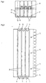
- the sheet metal blank 1 has two continuous, straight Edges (Fig. 1) or is on an edge with wedge-shaped Incisions 2 provided (Fig. 3).
- the blanks point on one edge tongues 3.4 and recesses 5.6. In these recesses engage tongues 7,8 on the opposite one Edge of the blank 1 while the tongues 3.4 in corresponding recesses 9.10 on them engage the opposite cutting edge.
- the blank 1 is with impressions 11 and corresponding Provide tips 12 or protuberances. Moreover the blank 1 has special impressions 13 with Tips 14, which act as stops for the front edge of a Serve hose. Before rolling or bending the Blank 1, an edge strip 15 is folded, see above that when bending the blank into a cylindrical Body a sleeve 16 with an inner collar 17 and after peaks 12, 14 pointing inside.
- the tabs 3,4,7,8 and the complementary recesses 5,6,9,10 keep the sleeve 16 form-fitting after bending together and make one partly straight, partly meandering extending butt 18, which is caused by welding, for example laser welding or by soldering can be easily closed.
- the incisions disappear when the blank is bent, and there is an opening 19 with a closed Edge (Fig. 3.5) as when using a blank without incisions (Fig. 1,2).
- the opening is for determined a spout, not shown, which as well the sleeve 16 is squeezed with a hose end so that the tips 12 penetrate into the wall of the hose.
- the tips 12 are dimensioned so that they are up to penetrate the usual tubular fabric and as it were interlock with the mesh of the fabric.
- the blank 1 instead of the indentations 11 and the tips 12 can the blank 1 also with grooves 20 and corresponding Ribs 21 may be provided.
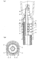
- a cut with straight lines facing each other Edges 22 can also be rolled or bent on a Side are shaped so that there is a bottle neck Taper 23 results in a spout 24 in shape one end of a 90 ° arc 25 encloses flat and is welded or soldered to it. This creates an annular space for loose insertion of a hose 26, the spout 24 and the sleeve 16 is crushed in the usual way.
- the hose connection consists of the pipe section or Elbow 25 with the spout 24 on one and a screw 28 at the other end that is bent over one Middle section are interconnected.
- the spout 24 is in the usual way, for example Scratch in with outer ribs 29 and with a stop bead 30 provided in front of which a loose union nut 31 is arranged.
- the hose connection has a screw connection outward-pointing bead 32, the more or less steadily in a triangular bead 33 or an inner bead 34 and then into a funnel-shaped expansion 35 passes.
- An O-ring 36 is relatively in the bead 33 large cross-section after screwing to a large extent under the influence of the counter connection is deformed and the bead 33 more or less fills. In this way, one also results very much high-density tight connection.
- the free end is designed as a nozzle 38 and into a funnel 39 opens, which is provided with a receptacle 40 for the sleeve 16 is.
- the sleeve 16 has a circumferential Groove 41, in the one through pairs of holes 42,43 Recording 40 inserted bracket 44 engages.
- the hose socket according to the invention When manufacturing the hose socket according to the invention no great effort is required; because it needs only from a tape with the width of the blank 1 to be cut off a corresponding piece.
- the Cutting can then be done in a single operation Stamping and embossing with the one shown in FIG. 1.3 Edge structure and the indentations 11,13 provided and if necessary be folded.
- the step then becomes a cylindrical cut Sleeve 16 bent or rolled, then only the contacting edges of the blank must be welded or soldered together.
- the resulting tube socket can be used in a conventional manner Way with a spout and with a Squeeze the end of the hose.
- the protrusions penetrate or the tips 12, 21 in the hose material and achieve - with the appropriate length - finally that steel mesh 45 embedded in the hose 26 this way the tips get caught in the braid, so that there is a bond, the holding force Is a multiple of conventional hose connections.
Landscapes
- Engineering & Computer Science (AREA)
- General Engineering & Computer Science (AREA)
- Mechanical Engineering (AREA)
- Joints That Cut Off Fluids, And Hose Joints (AREA)
- Rigid Pipes And Flexible Pipes (AREA)
- Shaping Of Tube Ends By Bending Or Straightening (AREA)
Description
Die Erfindung bezieht sich auf einen Schlauchanschluß mit einer Schlauchfassung in Gestalt einer Hülse zur Aufnahme einer Tülle und eines Schlauchendes, mit dem die Hülse verquetscht wird.The invention relates to a hose connection with a hose socket in the form of a sleeve Inclusion of a spout and a hose end with which the sleeve is crushed.
Derartige Schlauchfassungen dienen dazu, Schläuche, beispielsweise Hydraulikschläuche mit Anschlüssen an Maschinen lösbar zu verschrauben. Dies geschieht mit Hilfe eines Schlauchanschlusses mit einer in den Schlauch, beispielsweise einen Hochdruckschlauch, eingreifenden mit Außenrillen oder -rippen und einem Anschlagwulst versehenen Tülle und einer am anderen Ende angeordneten Verschraubung mit einer losen Überwurfmutter zum Verschrauben mit einem Gegenanschluß, beispielsweise einem Rohrende. Angesichts der zum Teil hohen bis sehr hohen Drücke im Schlauch bedarf es einer dauerhaften und dem jeweiligen Druck gewachsenen Verbindung zwischen der Fassung bzw. Hülse, dem Schlauchende und der Tülle.Such hose sockets serve hoses, for example Hydraulic hoses with connections to machines screwable. This is done with the help a hose connection with one in the hose, for example, a high pressure hose engaging with outer grooves or ribs and a stop bead provided spout and one arranged at the other end Screw connection with a loose union nut for screwing with a counter connection, for example one Pipe end. In view of the sometimes high to very high Pressures in the hose require a permanent and that respective pressure grown connection between the Socket or sleeve, the hose end and the spout.
Herkömmliche Schlauchfassungen besitzen daher im Querschnitt etwa dreieckige, quer zu der Längsachse der Schlauchfassung verlaufende Innenrippen, die beim Verquetschen mehr oder minder tief in den nachgiebigen Schlauchwerkstoff eindringen und die Fassung dort verankern.Conventional hose sockets therefore have a cross-section approximately triangular, transverse to the longitudinal axis of the Inner ribs running inside the tube frame, which prevent pinching more or less deep in the compliant Penetrate hose material and anchor the socket there.
Die Innenrippen machen die herkömmlichen Schlauchfassungen teuer, weil die Hülsen üblicherweise durch spanende Bearbeitung aus Vollmaterial hergestellt werden. Dabei wird ein Rundstab zunächst abgelängt und alsdann aufgebohrt. Danach werden mit Hilfe eines Spezialwerkzeugs die Innenrippen aus dem noch verbliebenen rohrförmigen Vollmaterial spanend herausgearbeitet.The inner ribs make the conventional tube sockets expensive because the sleeves are usually machined Machining can be made from solid material. there a round rod is first cut to length and then drilled out. After that, using a special tool the inner ribs from the remaining tubular Solid material machined out.
Diese Verfahrensweise ist außerordentlich zeit- und materialaufwendig; denn der Materialanteil der fertigen Fassung macht nur etwa 25 bis 30% des ursprünglichen Volumens des abgelängten Stababschnitts aus. Demzufolge gehen etwa 70 bis 75% des Ausgangsvolumens in Form von Spänen verloren. Darüber hinaus kommen als Werkstoff für die Schlauchfassung nur gut zerspanbare, mithin höhere Gehalte an Blei, Schwefel und/oder Selen enthaltende Stähle in Frage. Je nach dem speziellen Verwendungszweck wäre es jedoch wünschenswert, in der Werkstoffauswahl freier zu sein. Hinzu kommt, daß es unter dem Einfluß des Wärmeeinbringens beim Löten oder Schweißen zu Gefügeänderungen kommen kann, bei denen die Werkstoffestigkeit verlorengeht.This procedure is extremely time and material consuming; because the material portion of the finished Socket only makes up about 25 to 30% of the original Volume of the section of rod cut to length. As a result, go about 70 to 75% of the initial volume in the form of Chips lost. In addition, come as a material for the hose socket is only easy to machine, and therefore higher Levels of lead, sulfur and / or selenium containing Steels in question. Depending on the specific purpose however, it would be desirable in the choice of materials to be more free. Add to that it is under the influence the introduction of heat during soldering or welding to structural changes can come where the material strength get lost.
Bei der Verwendung von Rohren zum Herstellen von Schlauchanschlüssen durch spanende Innenbearbeitung ist zwar der Materialverlust erheblich geringer. Daraus resultiert jedoch kein wesentlicher Kostenvorteil, weil die Rohre eine verhältnismäßig große Wanddicke besitzen müssen und als Ausgangsmaterial generell erheblich teurer sind als Rundstäbe gleichen Durchmessers. Um die Innenrippen aus der Rohrwandung durch Spanen herausarbeiten zu können, sind nämlich entsprechend dickwandige Rohre erforderlich.When using pipes to manufacture Hose connections due to internal machining the loss of material is considerably less. This results however no significant cost advantage because the pipes have a relatively large wall thickness must and as a raw material generally much more expensive are as round bars of the same diameter. To remove the inner ribs from the That is, being able to work out the pipe wall by machining accordingly thick-walled pipes required.
Bekannt ist aus der französischen Patentschrift 1 495 499 auch bereits eine Schlauchfassung für einen Schlauchanschluß, die aus einer Hülse und einem Ring mit nach innen gerichteten Vorsprüngen besteht. Im auf eine Tülle montierten Zustand ist der Ring zwischen Hülse und Schlauch angeordnet. Abgesehen davon, daß diese Schlauchfassung zweiteilig. ist und daher verhältnismäßig hohe Fertigungskosten verursacht, besteht hier die Gefahr, daß sich der Ring in oder aus der Hülse löst und es so zu Undichtigkeiten kommt.One is already known from French patent specification 1,495,499 Hose socket for a hose connection consisting of a sleeve and a ring with inward projections. Im on one In the assembled state, the ring is arranged between the sleeve and the hose. Apart from the fact that this hose socket in two parts. is and therefore causes relatively high manufacturing costs, there is here Risk of the ring coming loose in or out of the sleeve and causing leaks comes.
Der Erfindung liegt das Problem zugrunde, einen Schlauchanschluß mit einer Schlauchfassung zu schaffen, die sich bei geringem Materialverlust oder auch ohne Materialverlust mit geringem zeitlichem Aufwand herstellen läßt.The invention is based on the problem of having a hose connection to create a hose fitting that can be used with little material loss or produce without loss of material with little time leaves.
Die Lösung dieses Problems besteht in einem Schlauchanschluß mit einer Schlauchfassung aus einer aus beispielsweise kaltgewalztem Tiefziehblech oder -band bestehenden Hülse aus einem zu einem Zylinder gebogenen und an der Stoßkante über quer zu ihrer Längsachse verlaufende, in komplementäre Ausnehmungen eingreifende Zungen dauerhaft verbundenen Blechzuschnitt mit nach innen weisenden, kaltgeformten Vorsprüngen, beispielsweise in Gestalt von umlaufenden Spitzen, Ausstülpungen und Innenrippen.The solution to this problem is a hose connection with a Hose socket made of, for example, cold-rolled deep-drawn sheet metal existing or band sleeve from a bent into a cylinder and on the abutting edge across, transverse to its longitudinal axis, in complementary Tongues engaging recesses permanently connected Sheet metal blank with cold-formed projections pointing inwards, for example in the form of all-round tips, protuberances and inner ribs.
Eine derartige Schlauchfassung läßt sich aus entsprechend bemessenen rechteckigen Blechzuschnitten unter Verwendung von Kaltband herstellen, dessen Breite der Länge einer Zuschnittkante entspricht. Durch bloßes Unterteilen des Bandes mit Hilfe einer Schere lassen sich die Zuschnitte auf einfache Weise mit beliebiger Länge zwei ihrer Kanten herstellen; sie werden alsdann mit Hilfe eines Kaltarbeitswerkzeuges auf einer Seite mit den Vorsprüngen versehen. Dies kann beispielsweise mit Hilfe einer Rolle geschehen, die mit Rippen versehen ist und die Innenrippen aus dem Blechzuschnitt herausdrückt. Auf diese Weise ergibt sich ein Zuschnitt, der auf der einen Seite mit Rillen und auf der anderen Seite mit Rippen versehen ist Statt der Rippen oder auch zusätzlich kann der Zuschnitt - unter Verwendung einer Art Stachelrolle - durch Kaltverformen mit Eindrückungen und auf der anderen Seite mit Spitzen versehen werden.Such a hose socket can be dimensioned accordingly produce rectangular sheet metal blanks using cold strip, whose width corresponds to the length of a cutting edge. By simply dividing it up of the tape with the help of scissors, the blanks can be opened easily create two of their edges with any length; you will be then with the help of a cold work tool on one side with the Provide protrusions. This can be done using a role, for example happen, which is provided with ribs and the inner ribs from the Pushes the sheet metal blank out. In this way there is a cut that Grooves on one side and ribs on the other side is instead of the ribs or additionally can be cut - using a type Spiked roller - by cold forming with indentations and on the other side with tips.
Der kaltverformte Zuschnitt wird anschließend zu einem Zylinder gebogen. Die Stoßkanten werden alsdann durch Verschweißen oder Verlöten dauerhaft miteinander verbunden. Vor dem Biegen kann der Zuschnitt jedoch auch noch in der Richtung quer zur Hülsenachse einseitig abgekantet werden, um eine einseitige, bis auf eine kleinere Öffnung geschlossene Hülse herzustellen.The cold-formed blank then becomes one Cylinder bent. The butt edges are then through Welding or soldering permanently connected. However, the blank can also be cut before bending folded on one side in the direction transverse to the sleeve axis be a one-sided, except for a smaller one To produce the opening of the closed sleeve.
Um die Haltbarkeit und die Formbeständigkeit der Hülse beim Löten oder Schweißen zu verbessern, können die Stoßkanten auch mäanderartig verlaufen. Ein solcher Stoßkantenverlauf ergibt sich, wenn der Zuschnitt im Bereich einer Stoßkante durch Stanzen mit Zungen und die gegenüberliegende Zuschnittseite mit komplementären, etwa Ω-förmigen Ausnehmungen versehen ist. Die beiden einander gegenüberliegenden Kanten brauchen nicht konturen- bzw. deckungsgleich zu verlaufen; denn es erhöht die Festigkeit der beim Biegen zu einem Zylinder entstehenden zunächst formschlüssigen Verbindung an der Stoßstelle, wenn es hier zu einer Kaltverformung oder auch Kaltverschweißung an den einander berührenden Kanten des Zuschnitts kommt.The durability and dimensional stability of the sleeve can improve when soldering or welding Butt edges are also meandering. Such a Butt edge course results when the cut in Area of a butt edge by punching with tongues and the opposite cut side with complementary, approximately Ω-shaped recesses is provided. The two opposing edges do not need contours- or to be congruent; because it increases the strength of the resulting when bending into a cylinder first a positive connection at the joint, if there is a cold deformation here too Cold welding on the contacting edges of the Cutting comes.
Beim Herstellen der Hülse kann ein einseitig abgekanteter Zuschnitt so verformt werden, daß die Hülse einen nach innen weisenden Kragen erhält. Dabei kommt es wegen des erheblich geringeren freien Querschnitts des Kragens zu einer erheblichen Materialverformung mit einer entsprechend hohen Kaltverfestigung. Dies läßt sich jedoch weitgehend vermeiden, wenn die beim Abkanten entstehende Zuschnittkante zunächst durch Stanzen mit beispielsweise keilförmigen Einschnitten versehen wird, deren einander gegenüberliegenden Kanten beim Kaltformen des Kragens aneinander zu liegen kommen.When manufacturing the sleeve, one can be folded on one side Be shaped so that the sleeve one collar facing inwards. It happens because of the considerably smaller free cross-section of the collar to a significant material deformation with a corresponding high work hardening. However, this can be done Avoid as much as possible if the First cut edge by punching with, for example wedge-shaped incisions are provided, the one another opposite edges when cold-forming the collar come to rest against each other.
Die erfindungsgemäße Schlauchfassung eignet sich insbesondere für Schlauchanschlüsse, wie sie in den Unterlagen der deutschen Patentanmeldung 196 18 819.9 beschrieben sind.The hose socket according to the invention is particularly suitable for hose connections as described in the documents the German patent application 196 18 819.9 are.
Diese Schlauchanschlüsse bestehen aus einem Rohrstück, das einerseits als übliche Tülle ausgebildet ist, verschraubungsseitig jedoch über einen Außenwulst in eine Außensicke übergeht. Beides läßt sich ohne weiteres durch bloßes Kaltverformen, im wesentlichen durch Aufweiten und etwa axiales Drücken nach Art eines Einwärtsfaltens herstellen.These hose connections consist of a piece of pipe, which is designed on the one hand as a conventional grommet, on the screw side however over an outer bead in a Outer bead goes over. Both can be done easily by mere cold working, essentially by expanding and about inward axial pushing produce.
Da die Sicke - im Gegensatz zu einer herkömmlichen Rille für einen O-Ring - nicht spanend eingebracht oder mit Hilfe eines Hartmetallwerkzeugs eingerollt zu werden braucht, sondern durch Stauchen bzw. Drücken im Wege eines Einwärtsfaltens hergestellt wird, ergibt sich ohne großen Aufwand ein günstiger Sickenquerschnitt.Because the bead - in contrast to a conventional groove for an O-ring - not machined or with To be rolled in using a hard metal tool needs, but by upsetting or pushing in the way of inward folding is produced without great effort a cheap bead cross section.
Die Sicke befindet sich vorzugsweise am Fuß einer trichterförmigen Aufweitung, die den Übergang zu dem Querschnitt des Gegenanschlusses bzw. Rohrendes schafft. The bead is preferably at the base of a funnel-shaped Widening which is the transition to the cross section of the mating connector or pipe end.
Dabei kann der Schlauchanschluß verschraubungsseitig in etwa die Gestalt zweier über eine Einschnürung miteinander verbundener Konen besitzen. Die Sicke verläuft dann im Bereich der Einschnürung und besitzt vorteilhafterweise einen dreieckförmigen Querschnitt, der beim Verschrauben mit dem Gegenanschluß mehr oder minder vollständig von dem dann stark verformten Dichtungsring ausgefüllt wird.The hose connection can be screwed in such as the shape of two constricting each other have connected cones. The bead then runs in the area of constriction and advantageously has a triangular cross section, which at More or less screwing to the mating connector completely from the then deformed sealing ring is filled out.
Eine mit Spitzen versehene Schlauchfassung ergibt eine besonders feste Verbindung, weil die Spitzen in die rautenförmigen Maschen des Schlauchgewebes eingreifen. Die Zerreißfestigkeit ist besonders hoch, wenn es sich dabei um ein Drahtgewebe oder -geflecht handelt.A hose fitting with tips gives one particularly firm connection because the tips in the diamond-shaped Insert meshes of the tubular fabric. The Tear resistance is especially high when it is there is a wire mesh or mesh.
Um beim Anformen des Innenkragens ein trichterförmiges Aufweiten der Hülse zu vermeiden, kann im Bereich der Biegekante eine Ringscheibe angeordnet sein, um die sich beim Herstellen des Innenkragens der abgekantete Streifen des Blechs herumlegt.To create a funnel-shaped shape when the inner collar is formed Avoiding expansion of the sleeve can be in the area of Bending edge can be arranged around the washer when creating the inner collar, the folded strips of the sheet.
Die Schlauchfassung kann im Innern auch mit einem oder mehreren Anschlägen für das Schlauchende versehen sein, um das Schlauchende in einem gewissen Abstand von dem Innenkragen zu halten. Dieser Abstand ermöglicht beim Verquetschen des Schlauchs mit dem Anschlußnippel einerseits und der Hülse andererseits ein axiales Wachsen in den Freiraum zwischen den Anschlägen und dem Innenkragen.The hose socket can also be fitted with a or be provided with several stops for the hose end, around the end of the hose a certain distance from that Keep inner collar. This distance allows for Squeeze the hose with the connection nipple on the one hand and the sleeve, on the other hand, has an axial growth in the space between the stops and the inner collar.
Da die erfindungsgemäße Schlauchfassung ausschließlich durch Verformen hergestellt wird und allenfalls beim Stanzen von Ausnehmungen an einer oder an mehreren Kanten des Blechzuschnitts ein geringer Materialverlust eintritt, sind die Herstellungskosten im Vergleich zu einem Herstellen aus Vollmaterial durch spanende Bearbeitung sehr gering.Since the hose socket according to the invention exclusively is produced by deforming and at most when Punching recesses on one or more edges of the sheet metal blank a small loss of material occurs, the manufacturing costs are compared to a manufacture from solid material by machining very low.
Die Erfindung wird nachfolgend anhand von in der Zeichnung dargestellten Ausführungsbeispielen des näheren erläutert. In der Zeichnung zeigen:
- Fig. 1
- einen fertig bearbeiteten Blechzuschnitt mit geraden Längskanten,
- Fig. 2
- einen axialen Längsschnitt durch eine aus dem Zuschnitt der Fig. 1 geformte Hülse,
- Fig. 3
- einen mit Rillen und Rippen versehenen, fertig bearbeiteten Blechzuschnitt mit sägezahnartiger Längskante
- Fig. 4
- einen axialen Längsschnitt durch eine aus dem Blechzuschnitt der Fig. 3 geformte Hülse,
- Fig. 5
- eine Draufsicht auf die Hülse der Fig. 1 in axialer Richtung,
- Fig. 6
- einen Schlauchanschluß mit einer erfindungsgemäßen Schlauchfassung,
- Fig. 7
- eine erfindungsgemäße Schlauchfassung mit einer Tülle, deren freies Ende als Düse ausgebildet ist und
- Fig. 8
- einen Schnitt nach der Linie VIII-VIII in Fig. 7.
- Fig. 1
- a finished sheet metal blank with straight longitudinal edges,
- Fig. 2
- 2 shows an axial longitudinal section through a sleeve formed from the blank of FIG. 1,
- Fig. 3
- a finished sheet metal blank with grooves and ribs with a sawtooth-like longitudinal edge
- Fig. 4
- 3 shows an axial longitudinal section through a sleeve formed from the sheet metal blank of FIG. 3,
- Fig. 5
- 2 shows a plan view of the sleeve of FIG. 1 in the axial direction,
- Fig. 6
- a hose connection with a hose socket according to the invention,
- Fig. 7
- an inventive hose socket with a nozzle, the free end is designed as a nozzle and
- Fig. 8
- a section along the line VIII-VIII in Fig. 7.
Der Blechzuschnitt 1 besitzt zwei durchgehende, gerade
Kanten (Fig. 1) oder ist an einer Kante mit keilförmigen
Einschnitten 2 versehen (Fig. 3). Die Zuschnitte weisen
an einer Kante Zungen 3,4 sowie Ausnehmungen 5,6 auf. In
diese Ausnehmungen greifen Zungen 7,8 an der gegenüberliegenden
Kante des Zuschnitts 1 ein, während die Zungen
3,4 in entsprechende Ausnehmungen 9,10 an der ihnen
gegenüberliegenden Zuschnittkante eingreifen.The
Der Zuschnitt 1 ist mit Eindrückungen 11 und entsprechenden
Spitzen 12 oder Ausstülpungen versehen. Außerdem
besitzt der Zuschnitt 1 besondere Eindrückungen 13 mit
Spitzen 14, die als Anschläge für die Stirnkante eines
Schlauchs dienen. Vor dem Rollen bzw. Biegen des
Zuschnitts 1 wird ein Randstreifen 15 abgekantet, so
daß beim Biegen des Zuschnitts zu einem zylindrischen
Körper eine Hülse 16 mit einem Innenkragen 17 und nach
innen weisenden Spitzen 12,14 entsteht.The blank 1 is with
Die Laschen 3,4,7,8 und die komplementären Ausnehmungen
5,6,9,10 halten die Hülse 16 nach dem Biegen formschlüssig
zusammen und ergeben einen teils gerade, teils mäanderförmig
verlaufenden Stoß 18, der sich durch Schweißen,
beispielsweise Laserschweißen oder durch Löten
leicht verschließen läßt.The
Besitzt der Zuschnitt 1 Einschnitte 2 (Fig. 3), dann
verschwinden beim Biegen des Zuschnitts die Einschnitte,
und es entsteht eine Öffnung 19 mit einem geschlossenen
Rand (Fig. 3,5) wie bei der Verwendung eines Zuschnitts
ohne Randeinschnitte (Fig. 1,2). Die Öffnung ist für
eine nicht dargestellte Tülle bestimmt, die ebenso wie
die Hülse 16 mit einem Schlauchende so verquetscht wird,
daß die Spitzen 12 in die Wandung des Schlauchs eindringen.
Die Spitzen 12 sind so bemessen, daß sie bis in
das übliche Schlauchgewebe eindringen und sich gleichsam
mit den Maschen des Gewebes verhaken.If the blank 1 has incisions 2 (Fig. 3), then
the incisions disappear when the blank is bent,
and there is an
Anstelle der Eindrückungen 11 und der Spitzen 12 kann
der Zuschnitt 1 auch mit Rillen 20 und entsprechenden
Rippen 21 versehen sein.Instead of the
Ein Zuschnitt mit einander gegenüberliegenden geraden
Kanten 22 kann auch beim Einrollen bzw. Biegen an einer
Seite so geformt werden, daß sich eine flaschenhalsartige
Verjüngung 23 ergibt, die eine Tülle 24 in Gestalt
des einen Endes eines 90°-Bogens 25 flächig umschließt
und mit diesem verschweißt oder verlötet ist. Dabei entsteht
ein ringförmiger Zwischenraum zum losen Einstecken
eines Schlauchs 26, der mit der Tülle 24 und der Hülse
16 in üblicher Weise verquetscht wird.A cut with straight lines facing each other
Edges 22 can also be rolled or bent on a
Side are shaped so that there is a
Um den Schlauch 26 genau positionieren zu können, ist
die Hülse 16 mit einem Schauloch 27 versehen.In order to be able to position the
Der Schlauchanschluß besteht aus dem Rohrstück bzw.
Rohrbogen 25 mit der Tülle 24 am einen und einer Verschraubung
28 am anderen Ende, die über einen gebogenen
Mittelabschnitt miteinander verbunden sind. The hose connection consists of the pipe section or
Die Tülle 24 ist in üblicher Weise beispielsweise durch
Einkratzen mit Außenrippen 29 und mit einem Anschlagwulst
30 versehen, vor dem eine lose Überwurfmutter 31
angeordnet ist.The
Verschraubungsseitig besitzt der Schlauchanschluß einen
nach außen weisenden Wulst 32, der mehr oder minder
stetig in eine dreieckförmige Sicke 33 bzw. einen Innenwulst
34 und sodann in eine trichterförmige Aufweitung
35 übergeht.The hose connection has a screw connection
outward-pointing
In der Sicke 33 befindet sich ein O-Ring 36 verhältnismäßig
großen Querschnitts, der nach dem Verschrauben
unter dem Einfluß des Gegenanschlusses in starkem Maße
verformt wird und dabei die Sicke 33 mehr oder minder
ausfüllt. Auf diese Weise ergibt sich eine auch sehr
hohen Drücken gewachsene dichte Verbindung.An O-
An die Stelle der Tülle 24 mit einer Rohrverschraubung
kann auch eine gerade Tülle 37 treten, deren freies Ende
als Düse 38 ausgebildet ist und in einen Trichter 39
mündet, der mit einer Aufnahme 40 für die Hülse 16 versehen
ist. Um den Trichter 39 lösbar mit der Schlauchfassung
zu verbinden, besitzt die Hülse 16 eine umlaufende
Rille 41, in die ein durch Lochpaare 42,43 der
Aufnahme 40 gesteckter Bügel 44 eingreift.In place of the
Beim Herstellen der erfindungsgemäßen Schlauchfassung
ist kein großer Aufwand erforderlich; denn es braucht
lediglich von einem Band mit der Breite des Zuschnitts 1
ein entsprechendes Stück abgetrennt zu werden. Der
Zuschnitt kann dann in einem einzigen Arbeitsgang durch
Stanzen und Prägen mit der aus den Fig. 1,3 ersichtlichen
Kantenstruktur sowie den Eindrückungen 11,13 versehen
und gegebenenfalls abgekantet werden. In einem zweiten
Arbeitsschritt wird dann der Zuschnitt zu einer zylindrischen
Hülse 16 gebogen bzw. gerollt, wonach dann
nur noch die einander berührenden Kanten des Zuschnitts
miteinander verschweißt oder verlötet werden müssen. Die
dabei entstehende Schlauchfassung läßt sich in herkömmlicher
Weise mit einer Tülle versehen und mit einem
Schlauchende verquetschen. Dabei dringen die Vorsprünge
bzw. die Spitzen 12,21 in das Schlauchmaterial ein und
erreichen - bei entsprechender Länge - schließlich das
in den Schlauch 26 eingebettete Stahlgeflecht 45. Auf
diese Weise verhaken sich die Spitzen mit dem Geflecht,
so daß sich ein Verbund ergibt, dessen Haltekraft ein
Vielfaches herkömmlicher Schlauchanschlüsse beträgt.When manufacturing the hose socket according to the invention
no great effort is required; because it needs
only from a tape with the width of the blank 1
to be cut off a corresponding piece. The
Cutting can then be done in a single operation
Stamping and embossing with the one shown in FIG. 1.3
Edge structure and the
Claims (15)
- Hose connector with a hose mounting comprisinga sleeve (16) made from a sheet metal cut-out (1) formed into a cylinder and permanently bound at the abutting edges by means of tongues (3, 4, 7, 8) running transverse to its longitudinal axis and engaging in complementary recesses (5, 6, 9, 10)with inward facing cold-formed projections (12, 21).
- Hose connector according to Claim 1, characterised in that it has points (12) facing inwards.
- Hose connector according to Claim 1 or 2, characterised in that it has encircling internal ribs (21).
- Hose connector according to one of the claims 1 to 3, characterised in that it has at least one cold-formed external groove (20, 41).
- Hose connector according to Claim 4, characterised in that the recesses (5, 6, 9, 10) and the tongues (3, 4, 7, 8) have an Ω-shaped contour.
- Hose connector according to one of the claims 1 to 5, characterised in that it has a folded inner collar (17).
- Hose connector according to Claim 6, characterised in that a ring-shaped disk lies against the inner collar (17).
- Hose connector according to Claim 6 or 7, characterised in that the inner collar (17) has a sawtooth-shaped edge.
- Hose connector according to one of the claims 1 to 5, characterised in that it has a sleeve (16) with a bottleneck-shaped end (23).
- Hose connector according to one of the claims 1 to 9, characterised in that it has a sleeve (16) with an inspection hole (27).
- Hose connector according to one of the claims 1 to 10, characterised in that it has a pipe section (25) with a spout (24) and a screw connection (28) which on the screw connection side gives way via an external swelling (32) to an external bead (33).
- Hose connector according to Claim 11, characterised in that it has a seamless pipe section (24, 25).
- Hose connector according to Claim 10 or 11, characterised in that the bead (33) is situated at the foot of a funnel-shaped expansion (35).
- Hose connector according to one of the claims 10 to 13, characterised in that, on the screw connection side, it has a pipe end in the shape of two cones (32, 35) connected to one another via a constriction (34).
- Hose connector according to one of the claims 10 to 14, characterised in that the pipe section (24, 25) is made from a steel capable of being deep-drawn.
Applications Claiming Priority (3)
| Application Number | Priority Date | Filing Date | Title |
|---|---|---|---|
| DE19639794 | 1996-09-27 | ||
| DE19639794A DE19639794C2 (en) | 1996-09-27 | 1996-09-27 | Hose fitting and process for its manufacture |
| PCT/DE1997/002226 WO1998013637A1 (en) | 1996-09-27 | 1997-09-27 | Flexible hose sleeve |
Publications (2)
| Publication Number | Publication Date |
|---|---|
| EP0925467A1 EP0925467A1 (en) | 1999-06-30 |
| EP0925467B1 true EP0925467B1 (en) | 2003-03-05 |
Family
ID=7807105
Family Applications (1)
| Application Number | Title | Priority Date | Filing Date |
|---|---|---|---|
| EP97910228A Expired - Lifetime EP0925467B1 (en) | 1996-09-27 | 1997-09-27 | Flexible hose sleeve |
Country Status (7)
| Country | Link |
|---|---|
| US (1) | US6296283B1 (en) |
| EP (1) | EP0925467B1 (en) |
| JP (1) | JP2001501287A (en) |
| KR (1) | KR20000048670A (en) |
| DE (1) | DE19639794C2 (en) |
| ES (1) | ES2194188T3 (en) |
| WO (1) | WO1998013637A1 (en) |
Families Citing this family (20)
| Publication number | Priority date | Publication date | Assignee | Title |
|---|---|---|---|---|
| US6796586B2 (en) * | 2001-07-09 | 2004-09-28 | Twin Bay Medical, Inc. | Barb clamp |
| DE10307478A1 (en) * | 2003-02-21 | 2004-09-02 | Bayerische Motoren Werke Ag | Fitting for attaching high-pressure hose to armature comprises sleeve which fits over hose and has teeth on its inner surface which fit between coils of hose reinforcement |
| US7922212B2 (en) | 2003-10-17 | 2011-04-12 | Twin Bay Medical, Inc. | Barb clamp with smooth bore |
| US7922213B2 (en) | 2003-10-17 | 2011-04-12 | Twin Bay Medical, Inc. | Barb clamp with smooth bore |
| US8256802B2 (en) * | 2003-10-17 | 2012-09-04 | Twin Bay Medical, Inc. | Barb clamp with collet interlocks |
| US7134696B2 (en) * | 2004-01-23 | 2006-11-14 | Trans-Matic Mfg. Co., Incorporated | Compression cap |
| FR2870315B1 (en) * | 2004-05-14 | 2006-06-23 | Itt Mfg Enterprises Inc | ARRANGEMENT FOR THE CONNECTION OF A RIGID TUBE WITH A FLEXIBLE TUBE |
| US20080061555A1 (en) * | 2005-02-16 | 2008-03-13 | Colin Knight | Flared cone fitting |
| DE102005040850B4 (en) * | 2005-08-29 | 2010-09-02 | A. Kayser Automotive Systems Gmbh | Holding device for fixing a tubular element on a tubular body and method thereto |
| EP1930644A1 (en) * | 2006-12-05 | 2008-06-11 | Dömer GmbH & Co. KG | Sliding sleeve |
| US8561647B2 (en) | 2008-03-07 | 2013-10-22 | The Gates Corporation | Safety and indicator apparatus systems and methods for high pressure conduits |
| EP2133161A1 (en) * | 2008-06-10 | 2009-12-16 | Dömer GmbH & Co. KG | Laser-welded sliding sleeve |
| US8360479B2 (en) * | 2008-11-20 | 2013-01-29 | The Gates Corporation | Crimpable or swageable fluid power ferrules, couplings, systems and methods |
| US20100123309A1 (en) * | 2008-11-20 | 2010-05-20 | Marvin Miller | Crimpable or swageable fluid power ferrules couplings, systems and methods employing torque communication |
| US9857008B2 (en) * | 2008-11-20 | 2018-01-02 | Gates Corporation | Crimpable or swageable fluid power ferrules, couplings, systems and methods employing torque communication |
| US9605782B2 (en) | 2009-04-02 | 2017-03-28 | Saint-Gobain Performance Plastics Corporation | Sanitary retainer |
| IT1405437B1 (en) * | 2010-06-11 | 2014-01-10 | Astroflex Spa | FLEXIBLE METAL TUBE FOR GAS VEHICLE AND PROCESS OF MANUFACTURE OF THE SAME |
| US9273810B1 (en) * | 2012-02-14 | 2016-03-01 | Delafield Corporation | Metal hose fitting and flanged insert that safely conducts high velocity fluids/gases up to Mach 1 |
| JP6221951B2 (en) * | 2014-06-10 | 2017-11-01 | トヨタ自動車株式会社 | Piping connection structure |
| USD1001979S1 (en) * | 2021-05-26 | 2023-10-17 | Richard P. Rizzuto | Hose collar |
Family Cites Families (26)
| Publication number | Priority date | Publication date | Assignee | Title |
|---|---|---|---|---|
| US916076A (en) * | 1906-07-25 | 1909-03-23 | Erwin W Whitmore | Hose-coupling. |
| US1241626A (en) * | 1914-10-26 | 1917-10-02 | Fred C Schoenthaler | Hose-coupling. |
| US1454073A (en) * | 1922-10-09 | 1923-05-08 | Frank H Paradice | Hose mender, band, and coupling |
| US1778244A (en) * | 1926-05-22 | 1930-10-14 | Goodrich Co B F | Method of making hose couplings |
| US2142768A (en) * | 1937-08-04 | 1939-01-03 | Scovill Manufacturing Co | Pronged clinching finger hose coupling |
| US2179200A (en) * | 1938-07-06 | 1939-11-07 | Albert J Scholtes | Hose coupling |
| US2279437A (en) * | 1940-06-19 | 1942-04-14 | Samuel B Beugler | Hose connector |
| US2314000A (en) * | 1940-11-26 | 1943-03-16 | Scovili Mfg Company | High pressure hose coupling |
| US2273398A (en) * | 1941-05-02 | 1942-02-17 | Flex O Tube Company | Flexible hose coupling |
| US2374225A (en) * | 1941-10-04 | 1945-04-24 | Bowden Eng Ltd | Flexible hose coupling |
| US2481001A (en) * | 1945-01-01 | 1949-09-06 | Aeroquip Corp | Coupling for flexible hose |
| US2978263A (en) * | 1954-01-11 | 1961-04-04 | Mulconroy Company | Hose coupling having deformable sleeve with extrusion holes |
| US3017203A (en) * | 1957-07-19 | 1962-01-16 | W D Allen Mfg Co | Connectors for plastic hose |
| FR1495499A (en) | 1966-06-13 | 1967-09-22 | Raccords Anoflex Soc D | Method of fixing a metal fitting at the end of a flexible pipe |
| US3549180A (en) * | 1968-05-16 | 1970-12-22 | Scovill Manufacturing Co | Hose and hose coupling assembly |
| US3530900A (en) * | 1968-08-30 | 1970-09-29 | Murray Corp | Hose assembly |
| US3534988A (en) * | 1968-11-15 | 1970-10-20 | Ite Imperial Corp | Tube end mounted sleeve |
| ZA727913B (en) * | 1972-02-02 | 1973-12-19 | Btr Industries Ltd | Improvements in or relating to hose end fittings and inserts therefor |
| US4319774A (en) * | 1979-04-19 | 1982-03-16 | Eaton Corporation | Hose and coupling assembly |
| DE3003368A1 (en) * | 1980-01-31 | 1981-08-06 | Drägerwerk AG, 2400 Lübeck | Clamping sleeve for hose fittings - has lateral hole to monitor hose location |
| DE3822041C1 (en) * | 1988-06-30 | 1989-08-17 | Rasmussen Gmbh, 6457 Maintal, De | |
| DE4021746A1 (en) * | 1990-07-07 | 1992-01-16 | Gkn Automotive Ag | ENDLESS CLAMP RING FOR FASTENING BELLOWS |
| US5199751A (en) * | 1990-11-13 | 1993-04-06 | Dana Corporation | Pressure hose coupling collar and method for producing same |
| US5267758A (en) * | 1991-07-18 | 1993-12-07 | The Gates Rubber Company | Ferrule coupling having a C-shaped insert |
| GB2294422B (en) * | 1994-10-27 | 1998-09-16 | Bentley Harris Ltd | Ferrule |
| DE29623072U1 (en) * | 1996-05-10 | 1997-11-20 | Dietzel GmbH, 46509 Xanten | Hose connection |
-
1996
- 1996-09-27 DE DE19639794A patent/DE19639794C2/en not_active Expired - Fee Related
-
1997
- 1997-09-27 EP EP97910228A patent/EP0925467B1/en not_active Expired - Lifetime
- 1997-09-27 KR KR1019990702615A patent/KR20000048670A/en not_active Application Discontinuation
- 1997-09-27 WO PCT/DE1997/002226 patent/WO1998013637A1/en active IP Right Grant
- 1997-09-27 JP JP10515171A patent/JP2001501287A/en active Pending
- 1997-09-27 US US09/269,424 patent/US6296283B1/en not_active Expired - Fee Related
- 1997-09-27 ES ES97910228T patent/ES2194188T3/en not_active Expired - Lifetime
Also Published As
| Publication number | Publication date |
|---|---|
| US6296283B1 (en) | 2001-10-02 |
| JP2001501287A (en) | 2001-01-30 |
| EP0925467A1 (en) | 1999-06-30 |
| KR20000048670A (en) | 2000-07-25 |
| WO1998013637A1 (en) | 1998-04-02 |
| DE19639794C2 (en) | 2001-07-26 |
| DE19639794A1 (en) | 1998-04-02 |
| ES2194188T3 (en) | 2003-11-16 |
Similar Documents
| Publication | Publication Date | Title |
|---|---|---|
| EP0925467B1 (en) | Flexible hose sleeve | |
| DE19700583C2 (en) | Connection arrangement for connecting eyelets and thin metal pipes and method for their production | |
| DE4003379C2 (en) | High pressure hose connection and process for its manufacture | |
| DE69412792T2 (en) | METHOD FOR MAKING PIPE CONNECTIONS AND TOOL FOR CARRYING OUT THIS METHOD | |
| DE3009436C2 (en) | ||
| EP0048003A1 (en) | Non-disconnectible pipe joint | |
| DE2714757B2 (en) | Tube plate with tubes fastened in their holes, in particular for heat exchangers | |
| EP0111271B1 (en) | Pipe of plastic, especially for sewage | |
| DE2854676C2 (en) | Worm drive clamp | |
| EP0858568B1 (en) | Process for connecting a pipe with a press fitting and combination of press fitting, pipe and pressing device | |
| EP0555650A1 (en) | Adaptive device for pipe couplings | |
| WO2000031428A1 (en) | Synchronizing ring which is shaped without cutting | |
| WO2019002323A1 (en) | Press-fit sleeve | |
| DE19723594C2 (en) | Pipe connector | |
| DE3347503A1 (en) | SELF-LOCKING BOLT | |
| WO2000012925A1 (en) | Pipe connection | |
| DE102005000720C5 (en) | Pipe coupling Press | |
| DE1450382B2 (en) | TUBE SCREW CONNECTION | |
| EP1412117B1 (en) | Spacer element for a collet chuck and collet chuck | |
| DE102020129959A1 (en) | Expansion anchor and method of anchoring it | |
| DE4211959C2 (en) | ||
| DE2700516A1 (en) | Socket or sleeve pipe coupling - has outer clamp ring with internal cones to successively deform outer coupling member | |
| DE9412445U1 (en) | Inseparable pipe connection | |
| DE4137495C2 (en) | Pipe connection for pressure pipes | |
| AT409015B (en) | PIPE BOW FOR A RAINFALL PIPE |
Legal Events
| Date | Code | Title | Description |
|---|---|---|---|
| PUAI | Public reference made under article 153(3) epc to a published international application that has entered the european phase |
Free format text: ORIGINAL CODE: 0009012 |
|
| 17P | Request for examination filed |
Effective date: 19990421 |
|
| AK | Designated contracting states |
Kind code of ref document: A1 Designated state(s): ES GB IE IT |
|
| 17Q | First examination report despatched |
Effective date: 20011011 |
|
| GRAH | Despatch of communication of intention to grant a patent |
Free format text: ORIGINAL CODE: EPIDOS IGRA |
|
| GRAH | Despatch of communication of intention to grant a patent |
Free format text: ORIGINAL CODE: EPIDOS IGRA |
|
| GRAA | (expected) grant |
Free format text: ORIGINAL CODE: 0009210 |
|
| AK | Designated contracting states |
Designated state(s): ES GB IE IT |
|
| REG | Reference to a national code |
Ref country code: GB Ref legal event code: FG4D Free format text: NOT ENGLISH |
|
| REG | Reference to a national code |
Ref country code: IE Ref legal event code: FG4D Free format text: GERMAN |
|
| GBT | Gb: translation of ep patent filed (gb section 77(6)(a)/1977) | ||
| PGFP | Annual fee paid to national office [announced via postgrant information from national office to epo] |
Ref country code: GB Payment date: 20030903 Year of fee payment: 7 |
|
| PGFP | Annual fee paid to national office [announced via postgrant information from national office to epo] |
Ref country code: IE Payment date: 20030922 Year of fee payment: 7 |
|
| PGFP | Annual fee paid to national office [announced via postgrant information from national office to epo] |
Ref country code: ES Payment date: 20030924 Year of fee payment: 7 |
|
| REG | Reference to a national code |
Ref country code: ES Ref legal event code: FG2A Ref document number: 2194188 Country of ref document: ES Kind code of ref document: T3 |
|
| PLBE | No opposition filed within time limit |
Free format text: ORIGINAL CODE: 0009261 |
|
| STAA | Information on the status of an ep patent application or granted ep patent |
Free format text: STATUS: NO OPPOSITION FILED WITHIN TIME LIMIT |
|
| 26N | No opposition filed |
Effective date: 20031208 |
|
| PG25 | Lapsed in a contracting state [announced via postgrant information from national office to epo] |
Ref country code: IE Free format text: LAPSE BECAUSE OF NON-PAYMENT OF DUE FEES Effective date: 20040927 Ref country code: GB Free format text: LAPSE BECAUSE OF NON-PAYMENT OF DUE FEES Effective date: 20040927 |
|
| PG25 | Lapsed in a contracting state [announced via postgrant information from national office to epo] |
Ref country code: ES Free format text: LAPSE BECAUSE OF NON-PAYMENT OF DUE FEES Effective date: 20040928 |
|
| GBPC | Gb: european patent ceased through non-payment of renewal fee |
Effective date: 20040927 |
|
| REG | Reference to a national code |
Ref country code: IE Ref legal event code: MM4A |
|
| PG25 | Lapsed in a contracting state [announced via postgrant information from national office to epo] |
Ref country code: IT Free format text: LAPSE BECAUSE OF NON-PAYMENT OF DUE FEES;WARNING: LAPSES OF ITALIAN PATENTS WITH EFFECTIVE DATE BEFORE 2007 MAY HAVE OCCURRED AT ANY TIME BEFORE 2007. THE CORRECT EFFECTIVE DATE MAY BE DIFFERENT FROM THE ONE RECORDED. Effective date: 20050927 |
|
| REG | Reference to a national code |
Ref country code: ES Ref legal event code: FD2A Effective date: 20040928 |