EP2152424B1 - Zuführrolle für holzzerspanungsmaschine - Google Patents
Zuführrolle für holzzerspanungsmaschine Download PDFInfo
- Publication number
- EP2152424B1 EP2152424B1 EP08747334A EP08747334A EP2152424B1 EP 2152424 B1 EP2152424 B1 EP 2152424B1 EP 08747334 A EP08747334 A EP 08747334A EP 08747334 A EP08747334 A EP 08747334A EP 2152424 B1 EP2152424 B1 EP 2152424B1
- Authority
- EP
- European Patent Office
- Prior art keywords
- feed roller
- chipper
- lower feed
- claws
- rollers
- Prior art date
- Legal status (The legal status is an assumption and is not a legal conclusion. Google has not performed a legal analysis and makes no representation as to the accuracy of the status listed.)
- Active
Links
Images


Classifications
-
- B—PERFORMING OPERATIONS; TRANSPORTING
- B02—CRUSHING, PULVERISING, OR DISINTEGRATING; PREPARATORY TREATMENT OF GRAIN FOR MILLING
- B02C—CRUSHING, PULVERISING, OR DISINTEGRATING IN GENERAL; MILLING GRAIN
- B02C23/00—Auxiliary methods or auxiliary devices or accessories specially adapted for crushing or disintegrating not provided for in preceding groups or not specially adapted to apparatus covered by a single preceding group
- B02C23/02—Feeding devices
-
- A—HUMAN NECESSITIES
- A01—AGRICULTURE; FORESTRY; ANIMAL HUSBANDRY; HUNTING; TRAPPING; FISHING
- A01G—HORTICULTURE; CULTIVATION OF VEGETABLES, FLOWERS, RICE, FRUIT, VINES, HOPS OR SEAWEED; FORESTRY; WATERING
- A01G3/00—Cutting implements specially adapted for horticultural purposes; Delimbing standing trees
- A01G3/002—Cutting implements specially adapted for horticultural purposes; Delimbing standing trees for comminuting plant waste
-
- B—PERFORMING OPERATIONS; TRANSPORTING
- B02—CRUSHING, PULVERISING, OR DISINTEGRATING; PREPARATORY TREATMENT OF GRAIN FOR MILLING
- B02C—CRUSHING, PULVERISING, OR DISINTEGRATING IN GENERAL; MILLING GRAIN
- B02C18/00—Disintegrating by knives or other cutting or tearing members which chop material into fragments
- B02C18/06—Disintegrating by knives or other cutting or tearing members which chop material into fragments with rotating knives
- B02C18/14—Disintegrating by knives or other cutting or tearing members which chop material into fragments with rotating knives within horizontal containers
-
- B—PERFORMING OPERATIONS; TRANSPORTING
- B02—CRUSHING, PULVERISING, OR DISINTEGRATING; PREPARATORY TREATMENT OF GRAIN FOR MILLING
- B02C—CRUSHING, PULVERISING, OR DISINTEGRATING IN GENERAL; MILLING GRAIN
- B02C18/00—Disintegrating by knives or other cutting or tearing members which chop material into fragments
- B02C18/06—Disintegrating by knives or other cutting or tearing members which chop material into fragments with rotating knives
- B02C18/16—Details
- B02C18/22—Feed or discharge means
- B02C18/2225—Feed means
- B02C18/2283—Feed means using rollers
Definitions
- the present invention relates generally to chipper devices and, more specifically, the feed system including feed rollers.
- Chippers are used to reduce branches, trees, brush, and other bulk wood products into small chips.
- Chippers typically include a feed chute, a feed system for controlling the feed rate of wood products into the chipper, a chipping mechanism, a drive system for powering the feed system and the chipping mechanism, and a discharge chute.
- the feed chute cooperates with the feed system to move the wood products towards the chipping mechanism.
- a chipper according to preamble of claim 1 is known from US 2003 111566 .
- the present disclosure relates to a feed system that is configured to more effectively grab and pull brush and tree materials into the chipper.
- the system of the present disclosure is configured such that a large, heavy tree trunk can be continuously pulled into the chipper.
- the invention is defined in claims.
- a chipper is shown.
- the chipper 10 is mounted to a frame 12 that rests on wheels 14, which enable the chipper 10 to be conveniently moved.
- the depicted chipper 10 includes a feed chute 16, which is also commonly referred to as a feed table.
- the feed chute 16 can be any structure located at the rear of the chipper 10 that facilitates the loading of materials to be chipped into the chipper 10.
- the material to be chipped can be any material that the user desires to reduce to chips.
- the material is most commonly brush and tree parts, therefore, for convenience the material to be chipped will be referred to herein interchangeably as wood, trees, or brush.
- the chipper 10 in the depicted embodiment includes a feed system 18 that grabs and pulls brush from the feed chute 16 into a body portion 20 of the chipper 10 which houses cutters 80 (see Figure 3 ) that cut the brush into small chips.
- the cutters 80 are shown as blades mounted on a drum 81. However, it should be appreciated that the cutter can be any structure that is capable of breaking the material to be chipped into chips. Once the material is broken into small chips, the chips are then projected out of the chipper 10 through a discharge chute 22.
- the feed chute 16 is provided at the rear of the chipper 10 to facilitate the loading of brush and trees into the chipper 10.
- the feed chute 16 includes a flat table portion 24 (loading surface) and two angled side walls 26, 28. It should be appreciated that many other configurations of the feed chute 16 are possible. Feed chutes are described in greater detail in a related application filed on May 10, 2007 titled Wood Chipper Infeed Chute. Once the brush is grabbed by the feed system 18, the brush is moved into contact with the cutter drum 30 that is housed within the body 20 of the chipper 10. The cutter drum 30 spins cutting blades 80 at a high rate of speed which thereby reduces the brush and wood that contacts the drum 30 into small chips that are projected out the discharge chute 22. Drum arrangements are described in greater detail in a related application filed on May 10, 2007 titled Chipper Drum with Integral Blower (No. 60/928,928 ).
- the feed system 18 of the chipper includes an upper feed roller 32 and a lower feed roller 34.
- the upper feed roller 32 rotates counter clockwise and the lower feed roller 34 rotates clockwise to grab and pull material into the chipper 10.
- the rotation is powered by a hydraulic drive motor (not shown).
- the lower feed roller 34 is positioned closer to the chute 16 than the upper feed roller 32.
- the axis of the lower feed roller 34 is below the table portion 24 of the feed chute 16. At least the teeth on the lower feed roller 34 are projecting above the surface of the table 24.
- portions of the lower feed roller other than the teeth extend above the surface of the table 24.
- the upper and lower feed roller overlap when viewed from above.
- the overlapping portion of the upper and lower feed rollers measured horizontally in the front-to-back direction is less than the radius of the lower feed roller.
- the axis of the lower feed roller 34 does not overlap with the outer surface of the upper feed roller 32.
- a log 36 is shown being loaded into the chipper 10.
- the log 36 is shown on the table portion 24 of the chute 16 engaged with the lower feed roller 34.
- the lower feed roller 34 engages the bottom surface of the log 36 and drags the log 36 up against the upper feed roller 32.
- the upper feed roller 32 climbs the end of the log 36 and engages the top surface of the log 36. Then the upper and lower rollers 32, 34 together pull the log 36 into the chipper body 20.
- the relative position of the feed rollers enables the above sequence. It should be appreciated, that in alternative embodiments other relative positions are also possible.
- the axis of the lower feed roller 34 might overlap with the outer surface of the upper feed roller 32.
- the upper roller 32 is shown mounted to a bracket assembly 39 that allows the upper roller 32 to pivot up and down to adjust for the different thickness of logs and brush.
- the bracket assembly includes a pair of arms 38, 40 that rotatably connect to the first end 46 and the second end 48 of the upper feed roller 32.
- the arms 38, 40 have a length L 1 that extend in a front to back direction relative to the chipper body. Ends 41 of the arms 38, 40 pivotably attach to the body of the chipper 10 about a horizontal axis that extends across the width of the chipper.
- a cylinder 42 is attached to both arms 38, 40 to apply pressure and dampen the motion of the upper feed roller 32.
- the cylinders are active (powered), but it should be appreciated that in other embodiment they can be passive (not powered).
- a guard 44 is mounted between the arms 38, 40 on top of the feed roller 32 to prevent brush from entering the chipper 10 above the upper feed roller 32.
- the length L 1 of the arms in the depicted embodiment is greater than the diameter D 1 of the upper feed roller 32. In the depicted embodiment the length L 1 is about 30 inches and D 1 is about 20 inches.
- the length of the arms 38, 40 can have an affect on the ability of the upper feed roller 32 to climb the end of log 36. It should be appreciated that many other configurations of the bracket assembly 39 are possible.
- springs are attached to the arms to bias the upper feed roller 32 downwardly to ensure that the upper feed roller 32 solidly engages the logs.
- the upper feed-roller 32 is-shown-in Figure 6a .
- the upper feed roller 32 includes rows of claws 50 that define gripping paths.
- the claws 50 in adjacent rows are staggered such that the claws 50 in the same gripping path are spaced apart a distance D 2 which is twice the distance D 3 , which is the distance that each row is spaced apart.
- each row includes five claws 50 and there are a total of 10 rows equally spaced apart.
- Each of the claws 50 are spaced apart by a distance D 4 and each claw 50 has a length D 5 .
- D 4 is greater than D 5 ; therefore, there are gaps between the claw 50 columns.
- D 4 is about 4-5 inches and D 5 is about 3-4 inches. The gaps have a width equal to half of the difference between D 4 and D 5 .
- Each claw 50 has an asymmetric side profile that includes a sharp edge which enables it to dig into the surface of a log.
- the height H 1 of the claws 50 is related to the spacing D 2 . In the depicted embodiment the height H, and distance D 2 are configured such that one or more claws 50 are engaged in the surface of a log 36 at all times.
- the diameter of the upper feed roller is about 15-25 inches and the height of the teeth in each of the 10 rows is about 1 ⁇ 2 to 2 inches.
- the diameter of the lower feed roller is about 9-12 inches and the height of each of the teeth in the 6 rows is about 3 ⁇ 4 to 2 inches.
- the teeth have thickness T 1 between about to 11 ⁇ 2 inches and the top surface is angled ⁇ at between about 45-65 degrees relative to the surface that extends generally perpendicularly away from the feed roller.
- the teeth are asymmetrical in that they are configured to operate different depending on the direction of rotation.
- the teeth are configured to engage the material to be chipped more aggressively when pulling the material into the chipper than when backing the material out of the chipper.
- the claws are sized and spaced apart such that at least one claw of the upper feed roller and at least one claw of the lower feed roller engage the surface of a log held between the upper and lower feed rollers.
- a line connecting the tip of the claws in adjacent rows does not cross into the outer surface of the feed rollers.
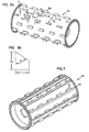
- the feed roller 61 is generally cylindrical in shape.
- the bars 63 run along the length of the feed roller 61 and connect to the claws 51 to provide auxiliary support to the claws 51.
- the bars 63 are also advantageous in that they aid in the feeding.
- the bars 63 can be equally or even more effective that the claws 51 in feeding brush.
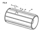
- the feed roller 60 is generally cylindrical in shape. Instead of rows of claws 50, the roller 60 includes a number of a ribbed plates 62 fixed to the outer surface of the feed roller 60. In the depicted embodiment the ribbed plates 62 are spaced apart by a distance D 6 . Each ribbed plate 62 includes a plurality of peaks 64 and valleys 66 thereon that are spaced apart by a distance D 7 . In the depicted embodiment the ribbed plates 62 are welded onto the outer surface of the feed roller 60. The ribbed plates 62 are configured to grab and pull material into the chipper 10 when rotated. It should be appreciated that many other variations of this embodiment are possible.
- the lower feed roller 34 is shown to include a number of claws 70 that are connected to each other and welded to the outer surface of the feed roller 34.
- the claws 70 are similar in configuration to those claws 50 illustrated in Figure 6a and described in detail above.
- the claws 70 in Figure 1 are connected together like the peaks 64 in the embodiment shown in Figure 8 .
- the claws 70 are shorter than the claws 50.
- the claws 70 in each row are offset from each other like the claws 50 in the embodiment shown in Figure 6a .
- the claws 70 and 50 are orientated such that when the upper feed roller 32 rotates counterclockwise and the lower feed roller 34 rotates clockwise, together they grab and pull materials to be chipped into the chipper 10. It should be appreciated that many other embodiments of the feed rollers are possible.
Landscapes
- Engineering & Computer Science (AREA)
- Food Science & Technology (AREA)
- Life Sciences & Earth Sciences (AREA)
- Biodiversity & Conservation Biology (AREA)
- Ecology (AREA)
- Forests & Forestry (AREA)
- Environmental Sciences (AREA)
- Debarking, Splitting, And Disintegration Of Timber (AREA)
Claims (10)
- Ein Häcksler, aufweisend:eine Beschickungsschurre (16), die eine Ladefläche (24) enthält, welche an einem Heck des Häckslers (10) angeordnet ist;einen Schneider (30), welcher zwischen einer Stirn des Häckslers und der Ladefläche (24) angeordnet ist;eine untere Vorschubrolle (34), welche zwischen der Ladefläche und dem Schneider (30) angeordnet ist, wobei eine Längsachse der unteren Vorschubrolle (34) unterhalb der Ladefläche (24) angeordnet ist und sich ein Teil der unteren Vorschubrolle (34) oberhalb der Ladefläche (24) erstreckt;eine obere Vorschubrolle (32) mit einer Längsachse, welche oberhalb der Ladefläche (24) und zwischen der Längsachse der unteren Vorschubrolle (34) und dem Schneider (30) angeordnet ist;dadurch gekennzeichnet, dass,wenn die obere Vorschubrolle (32) in einer abgesenkten Position ist, die äußere Oberfläche der oberen Vorschubrolle (32) die Längsachse der unteren Vorschubrolle (34) in einer vertikalen Richtung nicht überlappt.
- Häcksler nach Anspruch 1,
wobei die obere Vorschubrolle schwenkbar an dem Häcksler montiert ist, um einer oberen Vorschubrolle zu erlauben, sich hinauf und hinunter zu bewegen. - Häcksler nach Anspruch 2,
wobei die obere Vorschubrolle an Montagearmen befestigt ist, die eine Länge haben, die größer als ein Durchmesser der oberen Vorschubrolle ist. - Häcksler nach Anspruch 1,
wobei der Durchmesser der oberen Vorschubrolle größer ist als der Durchmesser der unteren Vorschubrolle. - Häcksler nach Anspruch 1,
wobei die oberen und die unteren Vorschubrollen eine Vielzahl von auf den oberen und den unteren Vorschubrollen voneinander beabstandeten Klauen umfassen,
wobei die Klauen in axialen Reihen auf den Vorschubrollen angeordnet sind und die Klauen in angrenzenden Reihen versetzt sind,
wobei die Klauen asymmetrisch sind, so dass sie verschieden arbeiten, wenn sie sich im Uhrzeigersinn oder gegen den Uhrzeigersinn drehen,
wobei sich die untere Vorschubrolle oberhalb der Ladefläche erstreckt, so dass sich mehr als die Klauen auf der unteren Vorschubrolle oberhalb der Ladefläche erstreckt. - Häcksler nach Anspruch 1
wobei die oberen und die unteren Vorschubrollen eine Vielzahl von auf den oberen und den unteren Vorschubrollen voneinander beabstandeten Klauen umfassen,
wobei der Durchmesser oder oberen und der unteren Vorschubrollen und die Höhe der Klauen hierauf so ausgeführt sind, dass zumindest eine der oberen Vorschubrolle und zumindest eine Klaue der unteren Vorschubrolle mit der Oberfläche eines Baumstammes, der zwischen den oberen und den unteren Vorschubrollen gehalten wird, in Eingriff gelangen,
wobei eine Linie, die die Spitzen der Klauen in angrenzenden Reihen verbindet, die äußere Oberfläche der Vorschubrollen nicht kreuzt. - Ein Häckslervorschubsystem, aufweisend:eine untere Vorschubrolle (34);eine obere Vorschubrolle (32);wobei die Rotationsachsen der oberen und unteren Vorschubrollen (32, 34) in der Stirn-nach-Heck-Richtung versetzt sind,dadurch gekennzeichnet, dasseine Achse der unteren Vorschubrolle (34) näher an einer Ladefläche (24) ist als die Achse der oberen Vorschubrolle (32), so dass zu häckselndes Material mit der unteren Vorschubrolle (34) in Eingriff gelangt, bevor es mit der oberen Vorschubrolle (32) in Eingriff gelangt.
- Vorschubsystem nach Anspruch 7,
wobei zumindest ein Teilbereich der oberen Vorschubrolle einen Teilbereich der unteren Vorschubrolle in einer vertikalen Richtung überlappt. - Vorschubsystem nach Anspruch 7,
wobei ein horizontal gemessener Überlappungsteilbereich der oberen und der unteren Vorschubrollen kleiner ist als der Radius der unteren Vorschubrolle. - Vorschubsystem nach Anspruch 7,
wobei die obere Vorschubrolle an dem Häcksler beweglich montiert ist, so dass sich die Vorschubrolle aufwärts und abwärts bewegen kann.
Applications Claiming Priority (2)
| Application Number | Priority Date | Filing Date | Title |
|---|---|---|---|
| US92892707P | 2007-05-10 | 2007-05-10 | |
| PCT/US2008/062207 WO2008140953A2 (en) | 2007-05-10 | 2008-05-01 | Wood chipper feed roller |
Publications (2)
| Publication Number | Publication Date |
|---|---|
| EP2152424A2 EP2152424A2 (de) | 2010-02-17 |
| EP2152424B1 true EP2152424B1 (de) | 2012-07-11 |
Family
ID=39671691
Family Applications (1)
| Application Number | Title | Priority Date | Filing Date |
|---|---|---|---|
| EP08747334A Active EP2152424B1 (de) | 2007-05-10 | 2008-05-01 | Zuführrolle für holzzerspanungsmaschine |
Country Status (3)
| Country | Link |
|---|---|
| US (2) | US8567706B2 (de) |
| EP (1) | EP2152424B1 (de) |
| WO (1) | WO2008140953A2 (de) |
Families Citing this family (18)
| Publication number | Priority date | Publication date | Assignee | Title |
|---|---|---|---|---|
| US7896274B2 (en) | 2006-01-30 | 2011-03-01 | Vermeer Manufacturing Company | Machine with snag anvil |
| WO2010144427A2 (en) | 2009-06-08 | 2010-12-16 | Vermeer Manufacturing Company | Material reducing apparatus having features for enhancing reduced material size uniformity |
| US20120255648A1 (en) * | 2011-04-08 | 2012-10-11 | Gray David A | Log Chipper with Log Jam Clearing Feature |
| US20130200188A1 (en) | 2012-02-01 | 2013-08-08 | Vermeer Manufacturing Company | Sizing screens for comminuting machines |
| US9505007B2 (en) | 2012-02-01 | 2016-11-29 | Vermeer Manufacturing Company | Deflection structure for tub grinder |
| WO2013188863A1 (en) * | 2012-06-16 | 2013-12-19 | Michael Boyd Morey | Waste and brush collection and processing system |
| US20140166790A1 (en) * | 2012-12-13 | 2014-06-19 | Vermeer Manufacturing Company | Method and Apparatus for Maintaining a Feed Roller Parallel to an Infeed Floor Through its Range of Motion |
| US10507469B2 (en) * | 2013-01-18 | 2019-12-17 | Kurt M. Schie | Wood chipper |
| FR3034030B1 (fr) * | 2015-03-23 | 2019-06-07 | Institut National De Recherche Pour L'agriculture, L'alimentation Et L'environnement | Dispositif de protection pour dechiqueteuse |
| US10350608B2 (en) | 2016-05-03 | 2019-07-16 | Vermeer Manufacturing Company | In-feed systems for chippers or grinders, and chippers and grinders having same |
| WO2019036521A1 (en) | 2017-08-15 | 2019-02-21 | Vermeer Manufacturing Company | FEEDING SYSTEM FOR SHREDDERS OR SHREDDERS, AND SHREDDERS AND SHREDDERS HAVING SAME |
| US10625269B1 (en) | 2017-11-02 | 2020-04-21 | Jesse R. Peterson | Bi-directional rotation feed roller for tree processing devices |
| CA3099877A1 (en) | 2018-06-12 | 2019-12-19 | Autostore Technology AS | An automated storage and retrieval system and a method of transporting storage containers between an automated storage and retrieval grid and a second location |
| CN111034581B (zh) * | 2019-12-30 | 2022-02-08 | 长沙中能装备制造有限公司 | 一种枝丫切碎机 |
| US11883827B2 (en) | 2020-01-24 | 2024-01-30 | Vermeer Manufacturing Company | Material reduction machine with dynamic infeed control |
| US11730085B2 (en) | 2020-03-02 | 2023-08-22 | Alamo Group Inc. | Wood chipper with drum speed monitoring system and centrifugal clutch |
| US20230066254A1 (en) | 2021-08-27 | 2023-03-02 | Vermeer Manufacturing Company | Material reduction machine with silenced chute |
| US20230149942A1 (en) | 2021-11-15 | 2023-05-18 | Vermeer Manufacturing Company | Material reduction machine with dynamic startup control |
Family Cites Families (76)
| Publication number | Priority date | Publication date | Assignee | Title |
|---|---|---|---|---|
| US2561069A (en) | 1944-01-21 | 1951-07-17 | Kingsburg Cotton Oil Co | Baled hay feeding device |
| US2821345A (en) | 1954-10-19 | 1958-01-28 | Muhlenbau Veb | Automatically operating control arrangement for pairs of rollers |
| US2927740A (en) | 1955-02-04 | 1960-03-08 | Deere & Co | Feed grinder with wagon unloader |
| US3182917A (en) | 1963-03-25 | 1965-05-11 | Wayne Manufacturing Co | Brush chipper safety control |
| US3523411A (en) | 1968-03-04 | 1970-08-11 | Sperry Rand Corp | Forage harvester drive |
| US3533871A (en) * | 1968-04-10 | 1970-10-13 | Armstrong Cork Co | Nonwoven tufted fabric by crimping |
| US3516539A (en) | 1968-05-13 | 1970-06-23 | Potlatch Forests Inc | Apparatus for separating and handling a cant and sideboards |
| FI62456C (fi) | 1981-03-18 | 1983-01-10 | Perusyhtyme Oy | Foerfarande foer matningsavbrytning i en transportabel hugganordning |
| US3701483A (en) | 1970-08-05 | 1972-10-31 | Marmon Group Inc | Railroad tie shredder |
| US3825192A (en) | 1973-01-22 | 1974-07-23 | Jeffrey Galion Inc | Feeding mechanism for reduction apparatus |
| ZA747312B (en) | 1973-11-17 | 1975-12-31 | Kloeckner Humboldt Deutz Ag | Method of determining and setting the width of the crushing gap and of measuring crushing tool wear in a a rotary crushing by aultrsonicmeans, and torary crusher for carrying out the method |
| US3863848A (en) | 1974-01-02 | 1975-02-04 | David J Mashuda | Giant Tree Chopper |
| US3955765A (en) | 1974-06-27 | 1976-05-11 | Kockum Industries, Inc. | Whole tree chipper |
| US4069911A (en) | 1975-04-17 | 1978-01-24 | Amf Incorporated | Band conveyor |
| DE2528828C2 (de) * | 1975-06-27 | 1982-09-09 | Maschinenfabrik Fahr Ag Gottmadingen, 7702 Gottmadingen | Antriebsanordnung für einen Feldhäcksler |
| US3990568A (en) | 1975-11-24 | 1976-11-09 | Weyerhaeuser Company | Press roll system for sawing machine |
| US4073377A (en) | 1976-04-20 | 1978-02-14 | Hesston Corporation | Feed rolls having automatic speed control |
| US4078592A (en) | 1976-12-20 | 1978-03-14 | Standal George M | Log feed mechanism for sawmills |
| US4078590A (en) | 1977-01-07 | 1978-03-14 | Morbark Industries, Inc. | Whole tree reducing apparatus |
| DE2730442A1 (de) | 1977-07-06 | 1979-01-25 | Hauni Werke Koerber & Co Kg | Anordnung zum schneiden von tabak |
| US4340137A (en) | 1978-03-27 | 1982-07-20 | Opcon, Inc. | Cant movement and aligning mechanism |
| US4338985A (en) * | 1979-10-19 | 1982-07-13 | Georgia-Pacific Corporation | Tree and brushwood harvester |
| FI59824B (fi) | 1979-11-08 | 1981-06-30 | Stroemberg Oy Ab | Foerfarande foer reglering av traeslipmaskin med kolvmatning |
| SE440992B (sv) | 1981-12-21 | 1985-09-02 | Kockums Ind Ab | Sjelvcentrerande inmatningsverk |
| US4650129A (en) * | 1982-03-03 | 1987-03-17 | Newell Industries, Inc. | Capped disc for hammer mill rotor |
| JPS60197395A (ja) | 1984-03-21 | 1985-10-05 | 日本たばこ産業株式会社 | 回転ドラム形カツタ−のナイフ送出装置 |
| US4633776A (en) | 1984-07-10 | 1987-01-06 | William Blackmore | Branch compactor |
| US4651936A (en) * | 1984-11-06 | 1987-03-24 | Gehl Company | Cutting knife bevel extender for forage harvesters |
| US4625924A (en) | 1985-08-27 | 1986-12-02 | Dresser Industries, Inc. | Hold down mechanism for reduction apparatus |
| DE3607980A1 (de) | 1986-03-11 | 1987-09-17 | Linck Masch Gatterlinck | Verfahren und vorrichtung zum zufuehren von baumstaemmen zu einer bearbeitungsmaschine |
| SE460464B (sv) | 1986-03-27 | 1989-10-16 | Jingsons Ab | Anordning foer kvistning, barkning och flishuggning vid en foeretraedesvis mobil enhet |
| US4799625A (en) | 1987-05-05 | 1989-01-24 | Ford New Holland, Inc. | Method and apparatus for adjusting a shear bar relative to a cutter head |
| AT390210B (de) | 1987-05-19 | 1990-04-10 | Kemetter Georg L | Vorrichtung zum aufbereiten von materialien |
| US4796819A (en) | 1987-11-16 | 1989-01-10 | Waterman Carl D | Wood chipper to be transported and powered by a tractor |
| US5137219A (en) | 1988-02-11 | 1992-08-11 | Wood Technology, Inc. | Wood chipper and infeed system |
| US4805676A (en) | 1988-02-16 | 1989-02-21 | Aikins Warren A | Automatic whole and multiple tree firewood/hog fuel processor |
| US4934612A (en) | 1988-03-28 | 1990-06-19 | Deere & Company | Automatic forage harvester shearbar adjusting |
| US5041057A (en) | 1988-07-21 | 1991-08-20 | Fmc Corporation | Corn cutter and system |
| US4943259A (en) | 1988-07-21 | 1990-07-24 | Fmc Corporation | Corn cutter and system |
| US4927088A (en) | 1989-02-27 | 1990-05-22 | Garbalizer Machinery Corp. | Tire feeding structure for tire shredding apparatus |
| US5020579A (en) * | 1990-05-21 | 1991-06-04 | Strong Manufacturing | Automatic infeed control |
| US5088532A (en) | 1990-06-05 | 1992-02-18 | Vermeer Manufacturing Company | Material feed control method and apparatus for a wood or brush chipping machine |
| US5062571A (en) | 1991-02-06 | 1991-11-05 | Rayco Enterprises, Inc. | Temperature sensing control for refrigeration system |
| US5205496A (en) | 1991-06-05 | 1993-04-27 | O.D.E. Investments Corporation | Universal grinder with reciprocal feeder |
| US5293479A (en) | 1991-07-08 | 1994-03-08 | Quintero Smith Incorporated | Design tool and method for preparing parametric assemblies |
| US5526885A (en) | 1992-08-19 | 1996-06-18 | Aktsionernoe Obschestvo Zakrytogo Tipa "Rossiiskaya Patentovannaya Tekhnika" (Ropat) | Hydraulic device for driving piles |
| US5230475A (en) | 1992-12-10 | 1993-07-27 | Banner Welder Incorporated | Conveyor system for shredder |
| DE9305854U1 (de) | 1993-04-20 | 1993-06-17 | Doppstadt, Werner, 5620 Velbert, De | |
| US5417265A (en) | 1993-10-12 | 1995-05-23 | Newman Machine Company, Inc. | Infeed method and apparatus for a machining device |
| US5881959A (en) | 1995-05-04 | 1999-03-16 | Cmi Corporation | Materials grinder with infeed conveyor and anvil |
| US5676238A (en) | 1995-06-07 | 1997-10-14 | U.S. Natural Resources, Inc. | Hold down rollers for a log conveyor |
| US5924637A (en) | 1997-04-16 | 1999-07-20 | Niederholtmeyer; Werner | Oversize tire and rubber debris shredder |
| US5947395A (en) | 1997-09-22 | 1999-09-07 | Peterson Pacific Corp. | Materials reducing machine |
| DE19854562A1 (de) | 1998-11-26 | 2000-05-31 | Claas Saulgau Gmbh | Einrichtung zur Überwachung der Einzugsbaugruppe einer landwirtschaftlichen Erntemaschine |
| US6853531B2 (en) | 1998-12-02 | 2005-02-08 | Corey Alexander Mather | Material processing machine |
| US6026871A (en) | 1999-03-30 | 2000-02-22 | Chapman; Bruce | Stump cutter safety system |
| US6293479B1 (en) | 1999-11-29 | 2001-09-25 | Clark Equipment Company | Feed control hydraulic circuit for wood chipper attachment |
| US6474579B1 (en) | 1999-12-10 | 2002-11-05 | Morbark, Inc. | Wood processing systems and methods of constructing and using them |
| US6357684B1 (en) * | 2000-10-31 | 2002-03-19 | Tramor, Inc. | Adjustable tension feed wheel assembly for a wood chipper |
| US7044409B2 (en) | 2000-11-08 | 2006-05-16 | Vermeer Manufacturing Company | Brush chipper and methods of operating same |
| US6722596B1 (en) | 2001-01-31 | 2004-04-20 | Tramor, Inc. | Multiple wheel feed wheel assembly for a wood chipper |
| US7083129B2 (en) | 2001-03-30 | 2006-08-01 | Reasonable Solutions, Inc. | Wood chipper having an infeed chute safety device |
| US6729567B1 (en) | 2001-07-31 | 2004-05-04 | Tramor, Inc. | Side feed wheel assembly for wood chipper |
| US6830204B1 (en) | 2001-12-10 | 2004-12-14 | Tramor, Inc. | Reversing automatic feed wheel assembly for wood chipper |
| US7441718B2 (en) | 2001-12-13 | 2008-10-28 | Morbark, Inc. | Wood reducing apparatus having hydraulically controlled material feed system |
| US6769836B2 (en) | 2002-04-11 | 2004-08-03 | Enviro-Pave, Inc. | Hot-in-place asphalt recycling machine and process |
| FI113478B (fi) | 2002-05-03 | 2004-04-30 | Metso Paper Inc | Menetelmä ja sovitelma puuannosten syöttämiseksi painehiomakoneeseen |
| US6955310B1 (en) | 2002-05-21 | 2005-10-18 | Tramor, Inc. | Remote control assembly for wood chipper |
| US6843435B2 (en) | 2002-11-18 | 2005-01-18 | Vermeer Manufacturing Company | Mill box for materials grinder |
| JP2004167797A (ja) | 2002-11-19 | 2004-06-17 | Hitachi Furukawa Kenki Kk | 樹枝粉砕機 |
| US7077345B2 (en) | 2002-12-12 | 2006-07-18 | Vermeer Manufacturing Company | Control of a feed system of a grinding machine |
| US7070132B1 (en) | 2003-08-21 | 2006-07-04 | Iowa State University Research Foundation, Inc. | Low-speed high-torque chipper-shredder machine |
| US7048212B2 (en) | 2003-12-11 | 2006-05-23 | Alan Carey | Sound activated safety system for a reduction mill |
| US7481386B2 (en) | 2005-09-26 | 2009-01-27 | Rayco Manufacturing, Inc. | Chipper feed mechanism with pulsating down pressure |
| US7874504B2 (en) | 2005-09-26 | 2011-01-25 | Rayco Manufacturing, Inc. | Chipper feed mechanism and throat opening sensor for use therewith |
| WO2008140956A2 (en) | 2007-05-10 | 2008-11-20 | Vermeer Manufacturing Company | System for controlling the position of a feed roller |
-
2008
- 2008-05-01 WO PCT/US2008/062207 patent/WO2008140953A2/en active Application Filing
- 2008-05-01 EP EP08747334A patent/EP2152424B1/de active Active
- 2008-05-01 US US12/599,629 patent/US8567706B2/en active Active
-
2013
- 2013-09-26 US US14/038,590 patent/US20140031185A1/en not_active Abandoned
Also Published As
| Publication number | Publication date |
|---|---|
| US20140031185A1 (en) | 2014-01-30 |
| US20100294869A1 (en) | 2010-11-25 |
| US8567706B2 (en) | 2013-10-29 |
| WO2008140953A2 (en) | 2008-11-20 |
| EP2152424A2 (de) | 2010-02-17 |
| WO2008140953A3 (en) | 2009-02-19 |
Similar Documents
| Publication | Publication Date | Title |
|---|---|---|
| EP2152424B1 (de) | Zuführrolle für holzzerspanungsmaschine | |
| US8684291B2 (en) | System for controlling the position of a feed roller | |
| EP2142302B1 (de) | Strauchhäcksler mit verbesserten zuführwalzen | |
| AU2014205361B2 (en) | Stump cutter disc with recessed tooth pockets | |
| EP2734348B1 (de) | Sicherheitsvorrichtung, rückflussreduktionsvorrichtung, anpassbare holzverarbeitungsvorrichtung und verfahren dafür zur abfallverarbeitung | |
| US8628034B2 (en) | Belt tensioning apparatus | |
| EP3485723B1 (de) | Erntemaschine für forstwirtschaft | |
| KR100920711B1 (ko) | 수목가지 파쇄기 | |
| US20100294868A1 (en) | Chipper drum with integral blower | |
| US10737275B2 (en) | Mill box for a horizontal grinder | |
| KR101472376B1 (ko) | 수목가지 파쇄기 | |
| US5094281A (en) | Debarking/delimbing apparatus | |
| BE1026646B1 (nl) | Gewassnijtoestel,landbouwmachine die zulk gewassnijtoestel bevat en werkwijze om het mes te verwijderen | |
| JP2010029776A (ja) | 破砕機 | |
| US5626298A (en) | Tub grinder with rear discharge hammer mill and angled shear plates | |
| US20190314825A1 (en) | Combined mulcher and chipper attachment | |
| CN212381723U (zh) | 悬挂式树枝粉碎机 | |
| CN210928701U (zh) | 一种多级粉碎机 | |
| CA2300524A1 (en) | Canter | |
| CN111869440A (zh) | 新型悬挂式枝条粉碎机 | |
| US4830288A (en) | Forage harvester | |
| JPS5939Y2 (ja) | コンバインや自走型脱穀機における穀稈搬送機構 |
Legal Events
| Date | Code | Title | Description |
|---|---|---|---|
| PUAI | Public reference made under article 153(3) epc to a published international application that has entered the european phase |
Free format text: ORIGINAL CODE: 0009012 |
|
| 17P | Request for examination filed |
Effective date: 20091120 |
|
| AK | Designated contracting states |
Kind code of ref document: A2 Designated state(s): AT BE BG CH CY CZ DE DK EE ES FI FR GB GR HR HU IE IS IT LI LT LU LV MC MT NL NO PL PT RO SE SI SK TR |
|
| AX | Request for extension of the european patent |
Extension state: AL BA MK RS |
|
| 17Q | First examination report despatched |
Effective date: 20101111 |
|
| GRAP | Despatch of communication of intention to grant a patent |
Free format text: ORIGINAL CODE: EPIDOSNIGR1 |
|
| DAX | Request for extension of the european patent (deleted) | ||
| GRAS | Grant fee paid |
Free format text: ORIGINAL CODE: EPIDOSNIGR3 |
|
| GRAA | (expected) grant |
Free format text: ORIGINAL CODE: 0009210 |
|
| AK | Designated contracting states |
Kind code of ref document: B1 Designated state(s): AT BE BG CH CY CZ DE DK EE ES FI FR GB GR HR HU IE IS IT LI LT LU LV MC MT NL NO PL PT RO SE SI SK TR |
|
| REG | Reference to a national code |
Ref country code: GB Ref legal event code: FG4D |
|
| REG | Reference to a national code |
Ref country code: CH Ref legal event code: EP |
|
| REG | Reference to a national code |
Ref country code: AT Ref legal event code: REF Ref document number: 565818 Country of ref document: AT Kind code of ref document: T Effective date: 20120715 |
|
| REG | Reference to a national code |
Ref country code: IE Ref legal event code: FG4D |
|
| REG | Reference to a national code |
Ref country code: DE Ref legal event code: R096 Ref document number: 602008017119 Country of ref document: DE Effective date: 20120906 |
|
| REG | Reference to a national code |
Ref country code: SE Ref legal event code: TRGR |
|
| REG | Reference to a national code |
Ref country code: NL Ref legal event code: VDEP Effective date: 20120711 |
|
| REG | Reference to a national code |
Ref country code: LT Ref legal event code: MG4D Effective date: 20120711 |
|
| PG25 | Lapsed in a contracting state [announced via postgrant information from national office to epo] |
Ref country code: BE Free format text: LAPSE BECAUSE OF FAILURE TO SUBMIT A TRANSLATION OF THE DESCRIPTION OR TO PAY THE FEE WITHIN THE PRESCRIBED TIME-LIMIT Effective date: 20120711 Ref country code: IS Free format text: LAPSE BECAUSE OF FAILURE TO SUBMIT A TRANSLATION OF THE DESCRIPTION OR TO PAY THE FEE WITHIN THE PRESCRIBED TIME-LIMIT Effective date: 20121111 Ref country code: LT Free format text: LAPSE BECAUSE OF FAILURE TO SUBMIT A TRANSLATION OF THE DESCRIPTION OR TO PAY THE FEE WITHIN THE PRESCRIBED TIME-LIMIT Effective date: 20120711 Ref country code: HR Free format text: LAPSE BECAUSE OF FAILURE TO SUBMIT A TRANSLATION OF THE DESCRIPTION OR TO PAY THE FEE WITHIN THE PRESCRIBED TIME-LIMIT Effective date: 20120711 Ref country code: CY Free format text: LAPSE BECAUSE OF FAILURE TO SUBMIT A TRANSLATION OF THE DESCRIPTION OR TO PAY THE FEE WITHIN THE PRESCRIBED TIME-LIMIT Effective date: 20120711 Ref country code: NO Free format text: LAPSE BECAUSE OF FAILURE TO SUBMIT A TRANSLATION OF THE DESCRIPTION OR TO PAY THE FEE WITHIN THE PRESCRIBED TIME-LIMIT Effective date: 20121011 |
|
| PG25 | Lapsed in a contracting state [announced via postgrant information from national office to epo] |
Ref country code: PL Free format text: LAPSE BECAUSE OF FAILURE TO SUBMIT A TRANSLATION OF THE DESCRIPTION OR TO PAY THE FEE WITHIN THE PRESCRIBED TIME-LIMIT Effective date: 20120711 Ref country code: PT Free format text: LAPSE BECAUSE OF FAILURE TO SUBMIT A TRANSLATION OF THE DESCRIPTION OR TO PAY THE FEE WITHIN THE PRESCRIBED TIME-LIMIT Effective date: 20121112 Ref country code: SI Free format text: LAPSE BECAUSE OF FAILURE TO SUBMIT A TRANSLATION OF THE DESCRIPTION OR TO PAY THE FEE WITHIN THE PRESCRIBED TIME-LIMIT Effective date: 20120711 Ref country code: LV Free format text: LAPSE BECAUSE OF FAILURE TO SUBMIT A TRANSLATION OF THE DESCRIPTION OR TO PAY THE FEE WITHIN THE PRESCRIBED TIME-LIMIT Effective date: 20120711 Ref country code: GR Free format text: LAPSE BECAUSE OF FAILURE TO SUBMIT A TRANSLATION OF THE DESCRIPTION OR TO PAY THE FEE WITHIN THE PRESCRIBED TIME-LIMIT Effective date: 20121012 |
|
| PG25 | Lapsed in a contracting state [announced via postgrant information from national office to epo] |
Ref country code: NL Free format text: LAPSE BECAUSE OF FAILURE TO SUBMIT A TRANSLATION OF THE DESCRIPTION OR TO PAY THE FEE WITHIN THE PRESCRIBED TIME-LIMIT Effective date: 20120711 |
|
| PG25 | Lapsed in a contracting state [announced via postgrant information from national office to epo] |
Ref country code: DK Free format text: LAPSE BECAUSE OF FAILURE TO SUBMIT A TRANSLATION OF THE DESCRIPTION OR TO PAY THE FEE WITHIN THE PRESCRIBED TIME-LIMIT Effective date: 20120711 Ref country code: CZ Free format text: LAPSE BECAUSE OF FAILURE TO SUBMIT A TRANSLATION OF THE DESCRIPTION OR TO PAY THE FEE WITHIN THE PRESCRIBED TIME-LIMIT Effective date: 20120711 Ref country code: RO Free format text: LAPSE BECAUSE OF FAILURE TO SUBMIT A TRANSLATION OF THE DESCRIPTION OR TO PAY THE FEE WITHIN THE PRESCRIBED TIME-LIMIT Effective date: 20120711 Ref country code: EE Free format text: LAPSE BECAUSE OF FAILURE TO SUBMIT A TRANSLATION OF THE DESCRIPTION OR TO PAY THE FEE WITHIN THE PRESCRIBED TIME-LIMIT Effective date: 20120711 Ref country code: ES Free format text: LAPSE BECAUSE OF FAILURE TO SUBMIT A TRANSLATION OF THE DESCRIPTION OR TO PAY THE FEE WITHIN THE PRESCRIBED TIME-LIMIT Effective date: 20121022 |
|
| PLBE | No opposition filed within time limit |
Free format text: ORIGINAL CODE: 0009261 |
|
| STAA | Information on the status of an ep patent application or granted ep patent |
Free format text: STATUS: NO OPPOSITION FILED WITHIN TIME LIMIT |
|
| PG25 | Lapsed in a contracting state [announced via postgrant information from national office to epo] |
Ref country code: SK Free format text: LAPSE BECAUSE OF FAILURE TO SUBMIT A TRANSLATION OF THE DESCRIPTION OR TO PAY THE FEE WITHIN THE PRESCRIBED TIME-LIMIT Effective date: 20120711 |
|
| 26N | No opposition filed |
Effective date: 20130412 |
|
| PG25 | Lapsed in a contracting state [announced via postgrant information from national office to epo] |
Ref country code: BG Free format text: LAPSE BECAUSE OF FAILURE TO SUBMIT A TRANSLATION OF THE DESCRIPTION OR TO PAY THE FEE WITHIN THE PRESCRIBED TIME-LIMIT Effective date: 20121011 |
|
| REG | Reference to a national code |
Ref country code: DE Ref legal event code: R097 Ref document number: 602008017119 Country of ref document: DE Effective date: 20130412 |
|
| PG25 | Lapsed in a contracting state [announced via postgrant information from national office to epo] |
Ref country code: MC Free format text: LAPSE BECAUSE OF FAILURE TO SUBMIT A TRANSLATION OF THE DESCRIPTION OR TO PAY THE FEE WITHIN THE PRESCRIBED TIME-LIMIT Effective date: 20120711 |
|
| REG | Reference to a national code |
Ref country code: CH Ref legal event code: PL |
|
| PG25 | Lapsed in a contracting state [announced via postgrant information from national office to epo] |
Ref country code: LI Free format text: LAPSE BECAUSE OF NON-PAYMENT OF DUE FEES Effective date: 20130531 Ref country code: CH Free format text: LAPSE BECAUSE OF NON-PAYMENT OF DUE FEES Effective date: 20130531 |
|
| REG | Reference to a national code |
Ref country code: IE Ref legal event code: MM4A |
|
| REG | Reference to a national code |
Ref country code: FR Ref legal event code: ST Effective date: 20140131 |
|
| PG25 | Lapsed in a contracting state [announced via postgrant information from national office to epo] |
Ref country code: IE Free format text: LAPSE BECAUSE OF NON-PAYMENT OF DUE FEES Effective date: 20130501 |
|
| PG25 | Lapsed in a contracting state [announced via postgrant information from national office to epo] |
Ref country code: FR Free format text: LAPSE BECAUSE OF NON-PAYMENT OF DUE FEES Effective date: 20130531 |
|
| PG25 | Lapsed in a contracting state [announced via postgrant information from national office to epo] |
Ref country code: MT Free format text: LAPSE BECAUSE OF FAILURE TO SUBMIT A TRANSLATION OF THE DESCRIPTION OR TO PAY THE FEE WITHIN THE PRESCRIBED TIME-LIMIT Effective date: 20120711 |
|
| PG25 | Lapsed in a contracting state [announced via postgrant information from national office to epo] |
Ref country code: TR Free format text: LAPSE BECAUSE OF FAILURE TO SUBMIT A TRANSLATION OF THE DESCRIPTION OR TO PAY THE FEE WITHIN THE PRESCRIBED TIME-LIMIT Effective date: 20120711 |
|
| PG25 | Lapsed in a contracting state [announced via postgrant information from national office to epo] |
Ref country code: LU Free format text: LAPSE BECAUSE OF NON-PAYMENT OF DUE FEES Effective date: 20130501 Ref country code: HU Free format text: LAPSE BECAUSE OF FAILURE TO SUBMIT A TRANSLATION OF THE DESCRIPTION OR TO PAY THE FEE WITHIN THE PRESCRIBED TIME-LIMIT; INVALID AB INITIO Effective date: 20080501 |
|
| PGFP | Annual fee paid to national office [announced via postgrant information from national office to epo] |
Ref country code: FI Payment date: 20200428 Year of fee payment: 13 |
|
| PGFP | Annual fee paid to national office [announced via postgrant information from national office to epo] |
Ref country code: SE Payment date: 20200508 Year of fee payment: 13 |
|
| PGFP | Annual fee paid to national office [announced via postgrant information from national office to epo] |
Ref country code: AT Payment date: 20200428 Year of fee payment: 13 |
|
| REG | Reference to a national code |
Ref country code: FI Ref legal event code: MAE |
|
| REG | Reference to a national code |
Ref country code: SE Ref legal event code: EUG |
|
| REG | Reference to a national code |
Ref country code: AT Ref legal event code: MM01 Ref document number: 565818 Country of ref document: AT Kind code of ref document: T Effective date: 20210501 |
|
| PG25 | Lapsed in a contracting state [announced via postgrant information from national office to epo] |
Ref country code: SE Free format text: LAPSE BECAUSE OF NON-PAYMENT OF DUE FEES Effective date: 20210502 Ref country code: FI Free format text: LAPSE BECAUSE OF NON-PAYMENT OF DUE FEES Effective date: 20210501 Ref country code: AT Free format text: LAPSE BECAUSE OF NON-PAYMENT OF DUE FEES Effective date: 20210501 |
|
| PGFP | Annual fee paid to national office [announced via postgrant information from national office to epo] |
Ref country code: IT Payment date: 20230510 Year of fee payment: 16 Ref country code: DE Payment date: 20230412 Year of fee payment: 16 |
|
| PGFP | Annual fee paid to national office [announced via postgrant information from national office to epo] |
Ref country code: GB Payment date: 20230412 Year of fee payment: 16 |