EP2151908A1 - Machine dynamoélectrique dotée d'un boîtier de connexion en plusieurs parties - Google Patents
Machine dynamoélectrique dotée d'un boîtier de connexion en plusieurs parties Download PDFInfo
- Publication number
- EP2151908A1 EP2151908A1 EP08013949A EP08013949A EP2151908A1 EP 2151908 A1 EP2151908 A1 EP 2151908A1 EP 08013949 A EP08013949 A EP 08013949A EP 08013949 A EP08013949 A EP 08013949A EP 2151908 A1 EP2151908 A1 EP 2151908A1
- Authority
- EP
- European Patent Office
- Prior art keywords
- plug
- housing
- dynamoelectric machine
- connector
- electrically conductive
- Prior art date
- Legal status (The legal status is an assumption and is not a legal conclusion. Google has not performed a legal analysis and makes no representation as to the accuracy of the status listed.)
- Granted
Links
Images

Classifications
-
- H—ELECTRICITY
- H02—GENERATION; CONVERSION OR DISTRIBUTION OF ELECTRIC POWER
- H02K—DYNAMO-ELECTRIC MACHINES
- H02K5/00—Casings; Enclosures; Supports
- H02K5/04—Casings or enclosures characterised by the shape, form or construction thereof
- H02K5/22—Auxiliary parts of casings not covered by groups H02K5/06-H02K5/20, e.g. shaped to form connection boxes or terminal boxes
- H02K5/225—Terminal boxes or connection arrangements
-
- H—ELECTRICITY
- H02—GENERATION; CONVERSION OR DISTRIBUTION OF ELECTRIC POWER
- H02K—DYNAMO-ELECTRIC MACHINES
- H02K11/00—Structural association of dynamo-electric machines with electric components or with devices for shielding, monitoring or protection
- H02K11/40—Structural association with grounding devices
Definitions
- the invention relates to a dynamoelectric machine with a multi-part connector housing having a hinge between the connector housing parts.
- Electrical equipment such as dynamo-electric machines are supplied via electrical connection cables by connectors with electrical energy.
- this connector also serves to transmit encoder signals and sensor signals as well as functional grounding.
- Functional grounding is of considerable importance for the trouble-free operation of electrical equipment. There is a general distinction between two types of grounding.
- the protective earthing which serves to protect humans and animals from electric shock and should only provide protection in the event of a fault
- the functional earthing is a functional part of the regular operation of the electrical equipment and is therefore essential for trouble-free operation of the respective electrical equipment ,
- the functional earth is usually not designed to take over protective conductor functions, thus the electrical safety of the personnel is not guaranteed when the protective conductor is connected to the functional earth connection.
- a conductive connection between protective earth and functional earth is usually created only in the vicinity of the actual earth.
- personal protection has priority in the matter of safety. It is only secondarily to pay attention to the functional earthing of an electrical equipment.
- Protective conductors must be dimensioned according to the DIN-VDE regulations (eg DIN-VDE 0100 part 540 earthing, protective conductor, equipotential bonding conductor), a correctly dimensioned protective conductor is only conditionally suitable for dissipating electromagnetic interference.
- Combined protective and functional earthing conductors must also have a large surface in addition to the prescribed cross-section.
- Plug housing is a ground pin of the plug conductively connected to the connector housing and the connector housing in turn conductive with the electrical equipment. A separate grounding line between the electrical equipment and the plug is therefore not necessary.
- This grounding line is mandatory if e.g. due to a mechanical load, the plug housing breaks in the rotary joint, and thus a conductive connection to the surface of the electrical equipment is interrupted.
- the engine would continue to be operable via the connecting lines but personal protection would be in the event of an accident, e.g. a ground fault of the winding is no longer given.
- a disadvantage of a separate grounding between Erdungspin the plug and the electrical equipment are the additional cost of such a high temperature stranded wire, an additional cable lug, as well as the installation of the line to the motor and plug, as well as a hole and a thread, for example in the engine mounting plate for mounting the cable shoe. Especially with compact motors low shaft height such an assembly is particularly complex.
- the present invention seeks to provide a dynamoelectric machine with a multi-part connector housing to create, which ensures adequate personal protection and especially in dynamo-electric machines small shaft height offers a mounting advantage without neglecting the protection of persons.
- a dynamoelectric machine with a stator in which a winding system is positioned, with at least one multi-part connector housing with a hinge between plug housing parts, with at least one connector with at least two plug-in elements, wherein at least one plug housing part is made of electrically conductive material, wherein this electrically conductive plug housing part is connected to at least one plug-in element by a flexible electrical line, wherein the dynamoelectric machine facing electrically conductive plug housing part is electrically connected to the electrically conductive surface of a motor housing of the dynamoelectric machine.
- a joint is understood to mean a joint which permits a movement of two adjacent plug housing parts not only in one plane but permits a three-dimensional degree of freedom according to a ball or hip joint of a human body.
- the two mutually movable connector housing parts which exert a movement due to a rotary joint, are now electrically connected to a flexible conduit.
- the connector housing part facing the dynamoelectric machine is connected directly to the housing of this dynamoelectric machine.
- the attached to the housing connector housing part is fixed and not rotatably mounted.
- the one or more connector housing parts of this connector are connected to one another via one or more rotary joints, so that an almost arbitrary orientation of the connector on the machine can be performed.
- this grounding line is not mechanically more loaded than the other motor connection lines that lead from the line pin in the connector housing through the connector housing parts for winding the dynamoelectric machine in the housing of the dynamoelectric machine.
- this grounding line is helical, so that even with a possible breakage in particular of the rotary joint for mechanical connection of the two connector housing parts, tearing off the grounding line is prevented, so that first tearing off the motor connection lines would occur before the personal protection would not be guaranteed.
- the plug housing part facing and facing the motor housing also has a ground pin so that the ground lead leads from this ground pin to the ground pin of the connector.
- a protective grounding of the motor housing is now achieved in that the motor housing facing the plug housing part, which advantageously forms a flange and is electrically conductive, is electrically conductively contacted with the metallic surface of the dynamoelectric machine.
- These contact surfaces between the plug housing part and the surface of the dynamoelectric machine must be free of grease and dirt. Furthermore, the surface of the machine should not be painted at least at this contact point and have no oxide layer in order to reduce the contact resistance.
- a welded connection screw connections may be preferable.
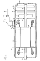
- FIG. 1 shows a connector housing 1, which is angled and has a hinge 2.
- the connector housing 1 is formed in two parts, wherein the invention is not limited to two parts but is applicable to three, four or more parts connector housing 1.
- the two plug housing parts 3 are mutually movable and each have a cavity in which run the connection lines of the electrical equipment, in particular the power supply lines of a dynamoelectric machine 15, as well as a grounding line 7 and / or not shown sensor lines.
- hinge 2 is also made hollow, all of these lines are installed protected.
- connection lines 6, and the grounding line 7 are guided on a connector 4.
- Connectors 4 are used to disconnect or connect lines. These lines lead, for example, a power or signals or are used for grounding.
- electrical connectors 4 one distinguishes the male part of a plug connection (with outwardly pointing contact pins) from the female part (with inwardly pointing contact openings).
- the male part in turn is a plug when attached to the end of a cable, or a built-in plug when it is firmly installed in a housing.
- the female part is a coupling when attached to the end of a cable or a socket when firmly mounted in a housing.
- Such compounds can also be produced by snap connections, which are comparatively easily manually detachable when needed and thus allow easy removal of the plug.
- the housing part of the overhead connector housing part 3 with the connector 4 is pulled axially over the plug-in elements 5 in order to ensure a contact protection there as well.
- This partial encapsulation likewise causes a certain dust and corrosion protection of the plug-in elements 5.
- the plug housing 1 now has a grounding connection via a grounding line 7 of its two plug housing parts 3, which leads from a grounding contact point 13 to a plug-in element 5 of the plug connector 4.
- a grounding line 7 of its two plug housing parts 3 which leads from a grounding contact point 13 to a plug-in element 5 of the plug connector 4.
- the lower part of the other plug housing part 3 advantageously has a flange 14, with which a contact to electrical equipment, in particular to the housing of a dynamoelectric machine 15 is provided.
- FIG. 2 shows a schematic representation of a connector housing 1, which is attached to a dynamoelectric machine 15, for example.
- the plug housing 1 is used to supply the electrical lines and the functional and / or protective grounding of the dynamoelectric machine 15.
- electrical signal lines or encoder signals can also be routed via or in the plug housing 1.
- a dynamoelectric machine 15 is not limited to only one connector housing 1, there may also be two or three such connector housing 1 on a dynamoelectric machine 15.
- the other connector housings are not necessarily designed as a multipart, i.
- Dynamo-electric machines 15 are conceivable which have either one or more multipart, in particular two-part plug housings 1, as well as dynamoelectric machines with a multi-part plug housing 1 and further one-part plug housings which have no mobility. This depends, inter alia. from the number of lines running in the connector housing, the size of the machine and the plug contacts.
- This dynamoelectric machine 15 is located in a motor housing 18, which has a stator 16 in which a winding system 17 is arranged.
- the power supply of this winding system 17 takes place, for example, as shown in principle, via connecting lines 6, which lead from the supply line 10 via the plug 11, the plug-in elements 5 of the connector 4 to the winding system 17.
- a rotor 26 drives a shaft 20 due to electromagnetic interaction with the stator 16.
- On this shaft 20 are, for example, an encoder 21, and / or a brake 23 whose Braking effect is achieved by one disc is axially displaceable against the other, and / or a fan 24.
- the fan 24 causes in operation via apertures 25 on the motor housing 18, a forced air movement, which is used for cooling.
- This electrical connection which is made in principle by screws 8
- the male housing part 3 having the connector is also grounded through the ground pin.
- An intact swivel joint 2 also creates a ground via its components, that is, the contacting half shells. In a fracture of the rotary joint 2 but is guaranteed by the grounding line 7 now in each case, the personal protection.
- the electrical contacting of the connector housing part 3 located on the motor housing 18 can also be done by welding, riveting and the other known in the art connection techniques.
- the area on the motor housing 18, which together with the flange 14 and / or the screws 8 is now intended to provide a ground connection to the plug housing part 3 and thus to the grounding contact point 13, must be free of grease and dirt, so that there are no excessively high contact resistances.
- the motor housing 18 should advantageously not yet be painted during the contacting of connector housing part 3 with motor housing 18 and have no oxide layers. To avoid subsequently resulting oxide layers at this contact point, it is advantageous to provide a welded ground connection between the flange 14 and the motor housing 18.
- the complete connector housing 1 can be pre-assembled with its connectors 4 and 5 plug elements as well as with the grounding lines 7. It only need the connecting lines 6 are performed for the winding system 17 through the connector housing 1 with its connector housing parts 3 and the hinge 2, to electrically connect it with the plug-in elements 5 of the connector 4.
- the metallic surface of the dynamoelectric machine would be under electrical voltage due to a ground fault of the winding system would be via the contact, for example via screws 8 or welds the flange 14 and thus mechanically and electrically connected lower metallic connector housing part 3 also under electrical tension.
- This voltage is now forwarded according to the invention via the ground pin 13, the grounding line 7 to a plug-in element 5, which is connected via a plug 11 with the system ground.
- connection lines 6, possibly further encoder or sensor lines or lines for functional grounding are now to be performed during assembly only through the cavities of the connector housing 1 and to contact the connector 4.
- grounding in particular for personal protection is thus created solely by contacting the flange 14 with the metallic surface of the dynamoelectric machine.
Landscapes
- Engineering & Computer Science (AREA)
- Power Engineering (AREA)
- Motor Or Generator Frames (AREA)
Priority Applications (4)
| Application Number | Priority Date | Filing Date | Title |
|---|---|---|---|
| EP08013949A EP2151908B1 (fr) | 2008-08-04 | 2008-08-04 | Machine dynamoélectrique dotée d'un boîtier de connexion en plusieurs parties |
| DE502008001484T DE502008001484D1 (de) | 2008-08-04 | 2008-08-04 | Dynamoelektrische Maschine mit einem mehrteiligen Steckergehäuse |
| US12/534,527 US8072103B2 (en) | 2008-08-04 | 2009-08-03 | Dynamoelectric machine having a multi-part plug housing |
| CN2009101640184A CN101645627B (zh) | 2008-08-04 | 2009-08-04 | 具有多部件的插头外壳的电动发电机 |
Applications Claiming Priority (1)
| Application Number | Priority Date | Filing Date | Title |
|---|---|---|---|
| EP08013949A EP2151908B1 (fr) | 2008-08-04 | 2008-08-04 | Machine dynamoélectrique dotée d'un boîtier de connexion en plusieurs parties |
Publications (2)
| Publication Number | Publication Date |
|---|---|
| EP2151908A1 true EP2151908A1 (fr) | 2010-02-10 |
| EP2151908B1 EP2151908B1 (fr) | 2010-10-06 |
Family
ID=40436472
Family Applications (1)
| Application Number | Title | Priority Date | Filing Date |
|---|---|---|---|
| EP08013949A Active EP2151908B1 (fr) | 2008-08-04 | 2008-08-04 | Machine dynamoélectrique dotée d'un boîtier de connexion en plusieurs parties |
Country Status (4)
| Country | Link |
|---|---|
| US (1) | US8072103B2 (fr) |
| EP (1) | EP2151908B1 (fr) |
| CN (1) | CN101645627B (fr) |
| DE (1) | DE502008001484D1 (fr) |
Families Citing this family (8)
| Publication number | Priority date | Publication date | Assignee | Title |
|---|---|---|---|---|
| DE102012004287A1 (de) * | 2012-03-01 | 2013-09-05 | Brose Fahrzeugteile GmbH & Co. Kommanditgesellschaft, Würzburg | Elektromotor |
| EP2824811A1 (fr) | 2013-07-11 | 2015-01-14 | Siemens Aktiengesellschaft | Enroulement de stator traversant enroulé sur un support de bobine |
| EP3076524B1 (fr) | 2015-03-30 | 2019-02-20 | Siemens Aktiengesellschaft | Composant de machine électrique et son procédé de fabrication |
| EP3089328B1 (fr) | 2015-04-27 | 2017-04-19 | Siemens Aktiengesellschaft | Rotor d'une machine électrique |
| EP3203609A1 (fr) | 2016-02-04 | 2017-08-09 | Siemens Aktiengesellschaft | Rotor pour une machine synchrone excitee par un aimant permanent, tige d'espace interpolaire pour un tel rotor et procede de fabrication d'un tel rotor |
| CN106059177A (zh) * | 2016-07-11 | 2016-10-26 | 河北超亚电子科技股份有限公司 | 一种连接器外插式的电机出线结构 |
| DE102020109000B4 (de) * | 2020-04-01 | 2022-02-17 | Bender Gmbh & Co. Kg | Verfahren und Vorrichtung zur Überwachung der Schutztrennung bei einem Stromerzeuger |
| JP7494070B2 (ja) * | 2020-09-17 | 2024-06-03 | タイコエレクトロニクスジャパン合同会社 | モーター |
Citations (1)
| Publication number | Priority date | Publication date | Assignee | Title |
|---|---|---|---|---|
| DE202006017131U1 (de) | 2006-10-12 | 2007-01-25 | Arnold & Richter Cine Technik Gmbh & Co. Betriebs Kg | Scheinwerfer zur Beleuchtung in Film-, Studio-, Event- oder Theaterumgebungen |
Family Cites Families (11)
| Publication number | Priority date | Publication date | Assignee | Title |
|---|---|---|---|---|
| US2634344A (en) * | 1951-01-10 | 1953-04-07 | Jr Joseph J Robinson | Reversing connector plug and adapter for three-phase motors |
| US4851725A (en) * | 1988-02-12 | 1989-07-25 | General Electric Company | Terminal block assembly for a leadless motor |
| US5317474A (en) * | 1992-05-08 | 1994-05-31 | The Whitaker Corporation | Module for telephone line conductor pair having single protector unit |
| US6074251A (en) * | 1997-06-09 | 2000-06-13 | The Siemon Company | Shielded high density patch panel |
| US5934096A (en) * | 1997-10-21 | 1999-08-10 | Hussmann Corporation | Wiring system for commercial refrigeration |
| US5949167A (en) * | 1998-07-22 | 1999-09-07 | Reliance Electric Industrial Company | Lead wire routing and sealing assembly for large electric motor |
| JP3966008B2 (ja) * | 2002-02-15 | 2007-08-29 | 株式会社豊田自動織機 | コンプレッサユニット |
| US6903473B2 (en) * | 2002-09-17 | 2005-06-07 | Asmo Co. Ltd. | Motor having connector housing |
| JP4007207B2 (ja) * | 2003-02-12 | 2007-11-14 | 株式会社デンソー | 車両用交流発電機 |
| US7135801B2 (en) * | 2004-08-24 | 2006-11-14 | Asmo Co., Ltd. | Motor apparatus having rotational position detector |
| US7025595B1 (en) * | 2005-04-13 | 2006-04-11 | Universal Scientific Industrial Co., Ltd. | Electronic device with adjustable housings |
-
2008
- 2008-08-04 DE DE502008001484T patent/DE502008001484D1/de active Active
- 2008-08-04 EP EP08013949A patent/EP2151908B1/fr active Active
-
2009
- 2009-08-03 US US12/534,527 patent/US8072103B2/en active Active
- 2009-08-04 CN CN2009101640184A patent/CN101645627B/zh active Active
Patent Citations (1)
| Publication number | Priority date | Publication date | Assignee | Title |
|---|---|---|---|---|
| DE202006017131U1 (de) | 2006-10-12 | 2007-01-25 | Arnold & Richter Cine Technik Gmbh & Co. Betriebs Kg | Scheinwerfer zur Beleuchtung in Film-, Studio-, Event- oder Theaterumgebungen |
Also Published As
| Publication number | Publication date |
|---|---|
| CN101645627A (zh) | 2010-02-10 |
| CN101645627B (zh) | 2013-06-19 |
| DE502008001484D1 (de) | 2010-11-18 |
| EP2151908B1 (fr) | 2010-10-06 |
| US20100026116A1 (en) | 2010-02-04 |
| US8072103B2 (en) | 2011-12-06 |
Similar Documents
| Publication | Publication Date | Title |
|---|---|---|
| EP2151908B1 (fr) | Machine dynamoélectrique dotée d'un boîtier de connexion en plusieurs parties | |
| DE102010041918B4 (de) | Statoranordnung umfassend einen Klemmenblock für eine elektrische Maschine | |
| EP3878060B1 (fr) | Connecteur d'alimentation haute tension et système de connecteur | |
| DE102014100142A1 (de) | Hochwasserfeste Steckerkonstruktion für eine widerstandsarme Leitung zwischen Erdstift und Gehäuse | |
| DE202014102609U1 (de) | Hochvolt-Verteilerbox insbesondere für ein Kraftfahrzeug | |
| WO2015110231A1 (fr) | Ensemble de liaison pour connecteur de puissance d'un moteur électrique | |
| DE102021112703A1 (de) | Berührgeschützte Schraubverbindungseinrichtung | |
| DE102016213757A1 (de) | Steckverbindung zum Koppeln von Hochvoltanschlüssen und System mit einer derartigen Steckverbindung | |
| DE102016118163A1 (de) | Lösbare verbindungseinrichtung für hohe ströme | |
| EP3171487B1 (fr) | Système d'entraînement et système de connection hybride pour système d'entraînement | |
| DE102014012350B3 (de) | Anschlussanordnung für ein elektrisches Gerät | |
| WO2012110138A1 (fr) | Dispositif de montage de commutateur d'interverrouillage, système haute tension pourvu d'un tel dispositif, et véhicule électrique ou hybride pourvu d'un dispositif de montage de commutateur d'interverrouillage et d'un système haute tension de ce type | |
| WO2016102057A1 (fr) | Module électronique pour un moteur électrique d'un entraînement de roue individuelle d'un véhicule à moteur, entraînement de roue individuelle et véhicule à moteur | |
| DE102013103331A1 (de) | Wechselrichter und Gleichstromanschlusseinheit für einen Wechselrichter | |
| DE102016211594A1 (de) | Elektrokontakt-Kupplung | |
| DE112018002100T5 (de) | Wischermotor | |
| DE112018008135B4 (de) | Elektromotor | |
| DE20022774U1 (de) | Kabel mit Anschlußelement | |
| CH689029A5 (de) | Sicherheitssteckverbindung mit einem Sicherheitsstecker und einer Sicherheitsbuchse mit durchgehender Isolation. | |
| DE102015207628A1 (de) | Gehäuse für eine Zwillingsanordnung von Elektromaschinen und Zwei-Motorenantrieb | |
| DE102016201328A1 (de) | Schraubkontakt, Leitungsverbindungssystem, Hochvoltsystem und Fahrzeug damit | |
| DE112014006573T5 (de) | Geformtes Modul | |
| DE202012104745U1 (de) | Durchführungsanordnung für ein Kabel | |
| DE202009005412U1 (de) | Einrichtung zur Verbindung zweier ein- oder mehrpoliger elektrischer Kabel miteinander | |
| DE102015226027A1 (de) | Öldichte elektrische Anschlussvorrichtung |
Legal Events
| Date | Code | Title | Description |
|---|---|---|---|
| PUAI | Public reference made under article 153(3) epc to a published international application that has entered the european phase |
Free format text: ORIGINAL CODE: 0009012 |
|
| 17P | Request for examination filed |
Effective date: 20090918 |
|
| AK | Designated contracting states |
Kind code of ref document: A1 Designated state(s): AT BE BG CH CY CZ DE DK EE ES FI FR GB GR HR HU IE IS IT LI LT LU LV MC MT NL NO PL PT RO SE SI SK TR |
|
| AX | Request for extension of the european patent |
Extension state: AL BA MK RS |
|
| GRAP | Despatch of communication of intention to grant a patent |
Free format text: ORIGINAL CODE: EPIDOSNIGR1 |
|
| GRAS | Grant fee paid |
Free format text: ORIGINAL CODE: EPIDOSNIGR3 |
|
| GRAA | (expected) grant |
Free format text: ORIGINAL CODE: 0009210 |
|
| AK | Designated contracting states |
Kind code of ref document: B1 Designated state(s): DE |
|
| AKX | Designation fees paid |
Designated state(s): DE |
|
| REF | Corresponds to: |
Ref document number: 502008001484 Country of ref document: DE Date of ref document: 20101118 Kind code of ref document: P |
|
| PLBE | No opposition filed within time limit |
Free format text: ORIGINAL CODE: 0009261 |
|
| 26N | No opposition filed |
Effective date: 20110707 |
|
| REG | Reference to a national code |
Ref country code: DE Ref legal event code: R097 Ref document number: 502008001484 Country of ref document: DE Effective date: 20110707 |
|
| PGFP | Annual fee paid to national office [announced via postgrant information from national office to epo] |
Ref country code: DE Payment date: 20251020 Year of fee payment: 18 |