EP3203609A1 - Rotor pour une machine synchrone excitee par un aimant permanent, tige d'espace interpolaire pour un tel rotor et procede de fabrication d'un tel rotor - Google Patents
Rotor pour une machine synchrone excitee par un aimant permanent, tige d'espace interpolaire pour un tel rotor et procede de fabrication d'un tel rotor Download PDFInfo
- Publication number
- EP3203609A1 EP3203609A1 EP16154281.6A EP16154281A EP3203609A1 EP 3203609 A1 EP3203609 A1 EP 3203609A1 EP 16154281 A EP16154281 A EP 16154281A EP 3203609 A1 EP3203609 A1 EP 3203609A1
- Authority
- EP
- European Patent Office
- Prior art keywords
- rotor
- pole
- magnets
- back bars
- laminated core
- Prior art date
- Legal status (The legal status is an assumption and is not a legal conclusion. Google has not performed a legal analysis and makes no representation as to the accuracy of the status listed.)
- Withdrawn
Links
Images

Classifications
-
- H—ELECTRICITY
- H02—GENERATION; CONVERSION OR DISTRIBUTION OF ELECTRIC POWER
- H02K—DYNAMO-ELECTRIC MACHINES
- H02K1/00—Details of the magnetic circuit
- H02K1/06—Details of the magnetic circuit characterised by the shape, form or construction
- H02K1/22—Rotating parts of the magnetic circuit
- H02K1/27—Rotor cores with permanent magnets
- H02K1/2706—Inner rotors
- H02K1/272—Inner rotors the magnetisation axis of the magnets being perpendicular to the rotor axis
- H02K1/274—Inner rotors the magnetisation axis of the magnets being perpendicular to the rotor axis the rotor consisting of two or more circumferentially positioned magnets
- H02K1/2753—Inner rotors the magnetisation axis of the magnets being perpendicular to the rotor axis the rotor consisting of two or more circumferentially positioned magnets the rotor consisting of magnets or groups of magnets arranged with alternating polarity
- H02K1/278—Surface mounted magnets; Inset magnets
-
- H—ELECTRICITY
- H02—GENERATION; CONVERSION OR DISTRIBUTION OF ELECTRIC POWER
- H02K—DYNAMO-ELECTRIC MACHINES
- H02K2201/00—Specific aspects not provided for in the other groups of this subclass relating to the magnetic circuits
- H02K2201/06—Magnetic cores, or permanent magnets characterised by their skew
Definitions
- the invention relates to a rotor for a permanent magnet synchronous machine, comprising a arranged on a shaft extending in the axial direction of the laminated core around whose circumference a plurality of poles are arranged, wherein at least one magnet is provided per pole.
- the invention further relates to a pole tail bar for such a rotor and a method for producing such a rotor.
- the magnets are exposed to strong centrifugal forces.
- centrifugal forces act on the magnets shear forces that can cause their misalignment in an insufficient fixation of the magnets.
- the shear forces occur in particular during acceleration and braking operations as well as with vibration and shock loading. In such cases, a bandage with bias can only partially hold the magnetic composite.
- the magnets may be formed, inter alia, as shell magnets.
- Shell magnets with two curved surfaces are eg in the EP 2 073 352 A1 described.
- a suitable adhesive is used in the formwork magnets, which are arranged around the circumference of laminated cores with cylindrical rotor laminations. Since the magnets must be secured against slipping, the bonding process is complicated. Alternatively, the rotor sheets have lateral stop lugs between the poles. In this embodiment, however, a staggering of the magnets proves to be difficult, since the bandage draws in gaps between the magnets and thus the bandaging is impaired.
- the invention has for its object to enable an arrangement of the magnets of a rotor, in which a particularly good security of the magnets is guaranteed against slipping.
- a rotor for a permanent magnet synchronous machine comprising a disposed on a shaft extending in the axial direction laminated core, around whose circumference a plurality of poles are arranged, wherein per pole at least one magnet is provided and pole pole rods between the poles are positioned in that, when viewed in the circumferential direction, each magnet bears, in each case with a first side and an opposite second side, against a pole back bar.
- the invention is based on the consideration that a reliable securing of the magnets against shearing or slipping is ensured by pole pole rods are provided between the row-shaped poles, which support the magnets laterally.
- Each magnet with its first side and its second side is in contact with two pole backsticks.
- Each pole pole in turn supports the magnets, in particular two poles.
- the pole pole rods are arranged between the poles and each magnet abuts on both sides over a large area or at least punctually on a poll tail rod, the pole back bars prevent the magnets from shearing along the surface of the laminated core due to the shear forces.
- the pole back bars are components separate from the magnets and the rotor laminations, which are formed in particular from a different material than the magnets and the rotor laminations.
- the pole back bars are spacers, which hold the magnets in their respective position by the contact with the magnets.
- the shape and size of the pole pole rods are matched with the shape, the size and the arrangement of the magnets on the laminated core.
- the pole back bars can be designed in several parts, so that between two poles in the axial direction, in particular a plurality of pole gap bars are arranged one behind the other. With regard to a reduction of the number of pole back rods and the effort for attaching the pole pole rods, only one pole back bar is provided between each two poles, which is preferably at least as long as the poles.
- the pole back bars are advantageously formed of a magnetically non-conductive material, e.g. Plastic, aluminum, etc.
- the pole back bars are fixed to the laminated core.
- this is a positive connection made by pins are provided on the pole back wires, which pins are directed radially inward in the assembled state of the rotor and engage in pole gaps between the poles.
- the pins are in particular in places where the adhesive tape is applied, interrupted so that the tape is not damaged.
- the Pole pole a staggering of the magnets is also possible.
- the pole back bars have at least two, preferably a plurality of sections, in the axial direction considered offset from each other.
- the stagger angle of the poles is predetermined in particular by the shape of the pole gap rods.
- the pole back bars are, according to a preferred embodiment, in full contact with the first and the second side of the magnets.
- the pole bridging rods have a plurality of webs extending transversely to the embodiment, via which they contact the magnets.
- the pole back bars support the sides of the magnets at one or more points at a point or over part of the side length. This embodiment is particularly material-saving.
- the magnets are designed as shell magnets.
- Shell magnets are usually arranged around cylindrical laminated cores with a circular cross-section of the individual sheets, so that the risk of slippage of the magnets is large without further security measures, whereby the requirements for a secure hold such Schalmagnete are particularly high.
- adhesive tape is applied to the laminated core below the magnets.
- This adhesive tape is applied in front of the pole back bars and the magnets in particular in individual rings around the circumference of the laminated core and serves only for fixing the magnets or pole pole rods.
- the adhesive tape in particular has no effect.
- the arrangement of magnets and pole back rods is bandaged.
- the magnets and pole pole rods are secured against the centrifugal forces during operation of the rotor.
- Runners usually used end discs.
- the pole back bars can be used here to ensure the function of the end plate. The end plate can thus be omitted.
- the pole crowbars have a plurality of radially outwardly open spaces. It is thus created a profiled surface, which is provided with several open spaces.
- the advantage of such a profiling is that the pole back bars can be used for balancing, in particular as an attachment for a balancing kit.
- the object is further achieved according to the invention by a poll tail rod for a runner according to one of the above embodiments.
- the pole gap bars are first fixed on the sheet metal package, in particular form-fitting. Subsequently, the magnets, magnetized or unmagnetized, are distributed axially between the pole back bars. Conceivable, however, are also other orders in the distribution of pole crow bars and the magnets on the laminated core. With unmagnetized magnets they are finally magnetized after bandaging.
- FIG. 2 is the stepwise structure of a rotor 2 according to the invention for use in a permanent magnet synchronous machine not shown here in detail, in particular in a servo motor.
- the rotor 2 comprises a shaft 4 extending in an axial direction A and a laminated core 6.
- the laminated core 6 is applied to the shaft 4.
- the next step will be around the scope the laminated core 6 adhesive tape 8 mounted in several annular strips.
- the adhesive tape 8 is used only for fixing permanent-magnet 10 and possibly pole pole rods 12, which are distributed in a third step on the circumference of the laminated core 6.
- the magnets 10 are configured in this embodiment as shell magnets and form a plurality of row-shaped poles 14 in the axial direction.
- the pole back bars 12 are all the same width and the same length and are made of a magnetically non-conductive material, such as aluminum or plastic.
- Each magnet 10 has a first side 16a extending in the axial direction A and an opposite second side 16b extending in the axial direction A.
- the pole back bars 12 are positioned so that each magnet 10 rests with its first side 16a on a pole tail bar 12 and rests with its second side 16b on another pole pole 12.
- the magnets are 12 over their entire surface with their first side 16a and second side 16b, ie there is a contact between the magnet 10 and the adjoining pole end pole 12 in particular over the entire length of the sides 16a, 16b.
- the runner 2 is bandaged by means of a bandage not shown here.
- a bandage not shown here.
- Bandage or end of the drum end plate 18 is provided. Their function can, however, be taken over by the pole back bars 12.
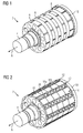
- pole back bars 12 have a plurality of sections 20, which are offset from one another in the axial direction A.
- the pole back bars 12 have pins 22 which are directed radially inward and fix the pole back bars 12 via a positive connection to the laminated core 6. Point to its outer side the pole gap bars 12 a lattice-shaped profiling.
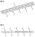
- FIG. 5 to FIG. 7 A second embodiment variant of the pole gussets 12 is made FIG. 5 to FIG. 7 seen.
- the pole back bars 12 in this case have a plurality of transverse to the axial direction A webs 24, via which they contact the sides 16a, 16b of the magnets 10 punctually.
- the pole gap bars 12 thus have a herringbone shape in a broader sense.
- each side 16a, 16b of a magnet 10 is supported by two webs 24.
- the pole back bars 12 of the second embodiment also have a plurality of sections 20, wherein the length of the webs 24 between the different sections 20 is varied so that a staggering of the magnets 10 in the axial direction 10 is made possible.
- the pole back bars 12 of both variants also have a plurality of intermediate spaces 26 which are open at least radially outward (see FIG FIG. 2 and FIG. 5 ). These hollow spaces can be used in particular for balancing the rotor 2.
Priority Applications (6)
| Application Number | Priority Date | Filing Date | Title |
|---|---|---|---|
| EP16154281.6A EP3203609A1 (fr) | 2016-02-04 | 2016-02-04 | Rotor pour une machine synchrone excitee par un aimant permanent, tige d'espace interpolaire pour un tel rotor et procede de fabrication d'un tel rotor |
| PCT/EP2016/077256 WO2017133800A1 (fr) | 2016-02-04 | 2016-11-10 | Rotor d'une machine synchrone à excitation par aimants permanents, barre d'espace interpolaire pour un tel rotor, et procédé de fabrication d'un tel rotor |
| EP16795296.9A EP3391511B1 (fr) | 2016-02-04 | 2016-11-10 | Rotor pour une machine synchrone excitee par un aimant permanent, tige d'espace interpolaire pour un tel rotor et procede de fabrication d'un tel rotor |
| JP2018538756A JP6639688B2 (ja) | 2016-02-04 | 2016-11-10 | 永久磁石励磁型同期機の回転子および回転子のための磁極間スペーサ部材 |
| US16/075,502 US11075554B2 (en) | 2016-02-04 | 2016-11-10 | Rotor for a permanent magnet synchronous machine, pole gap rod for such a rotor, and method for producing such a rotor |
| CN201680072900.4A CN108475949B (zh) | 2016-02-04 | 2016-11-10 | 永磁同步电机的转子,转子极间杆和制造该转子的方法 |
Applications Claiming Priority (1)
| Application Number | Priority Date | Filing Date | Title |
|---|---|---|---|
| EP16154281.6A EP3203609A1 (fr) | 2016-02-04 | 2016-02-04 | Rotor pour une machine synchrone excitee par un aimant permanent, tige d'espace interpolaire pour un tel rotor et procede de fabrication d'un tel rotor |
Publications (1)
| Publication Number | Publication Date |
|---|---|
| EP3203609A1 true EP3203609A1 (fr) | 2017-08-09 |
Family
ID=55299400
Family Applications (2)
| Application Number | Title | Priority Date | Filing Date |
|---|---|---|---|
| EP16154281.6A Withdrawn EP3203609A1 (fr) | 2016-02-04 | 2016-02-04 | Rotor pour une machine synchrone excitee par un aimant permanent, tige d'espace interpolaire pour un tel rotor et procede de fabrication d'un tel rotor |
| EP16795296.9A Active EP3391511B1 (fr) | 2016-02-04 | 2016-11-10 | Rotor pour une machine synchrone excitee par un aimant permanent, tige d'espace interpolaire pour un tel rotor et procede de fabrication d'un tel rotor |
Family Applications After (1)
| Application Number | Title | Priority Date | Filing Date |
|---|---|---|---|
| EP16795296.9A Active EP3391511B1 (fr) | 2016-02-04 | 2016-11-10 | Rotor pour une machine synchrone excitee par un aimant permanent, tige d'espace interpolaire pour un tel rotor et procede de fabrication d'un tel rotor |
Country Status (5)
| Country | Link |
|---|---|
| US (1) | US11075554B2 (fr) |
| EP (2) | EP3203609A1 (fr) |
| JP (1) | JP6639688B2 (fr) |
| CN (1) | CN108475949B (fr) |
| WO (1) | WO2017133800A1 (fr) |
Families Citing this family (1)
| Publication number | Priority date | Publication date | Assignee | Title |
|---|---|---|---|---|
| DE102019213448A1 (de) * | 2019-09-04 | 2021-03-04 | Volkswagen Aktiengesellschaft | Rotor für eine elektrische Maschine mit stegförmigen Halteelementen |
Citations (6)
| Publication number | Priority date | Publication date | Assignee | Title |
|---|---|---|---|---|
| US5323078A (en) * | 1991-12-20 | 1994-06-21 | Valeo Systemes D'essuyage | Permanent magnet rotor, and a magneto-dynamic machine, for example an electric motor not having a commutator but having such a rotor |
| EP1193826A2 (fr) * | 2000-08-23 | 2002-04-03 | Siemens Aktiengesellschaft | Rotor à aimant permanent pour un actionnement électrique à aimant permanent, en particulier un entraínement principal à courant alternatif |
| EP1914864A2 (fr) * | 2006-10-21 | 2008-04-23 | ESW GmbH | Agencement destiné à la fixation d'aimants permanents sur des rotors tournant rapidement de machines électriques |
| US20090001839A1 (en) * | 2006-01-10 | 2009-01-01 | Okubo Masayuki | Rotating Electrical Machine |
| EP2073352A1 (fr) | 2007-12-17 | 2009-06-24 | Siemens Aktiengesellschaft | Machine synchrone à excitation permanente dotée d'aimants à coque |
| EP2139100A1 (fr) * | 2008-06-27 | 2009-12-30 | Siemens Aktiengesellschaft | Machine synchrone à aimants permanents dotée d'une ondulation de couple réduite |
Family Cites Families (28)
| Publication number | Priority date | Publication date | Assignee | Title |
|---|---|---|---|---|
| JPS61138375U (fr) | 1985-02-15 | 1986-08-27 | ||
| JPH099539A (ja) * | 1995-06-23 | 1997-01-10 | Meidensha Corp | 永久磁石回転電機の回転子 |
| JP2004236373A (ja) | 2003-01-28 | 2004-08-19 | Tsunehiko Yamazaki | ブラシレスモータ |
| JP4295319B2 (ja) | 2003-06-20 | 2009-07-15 | シーメンス アクチエンゲゼルシヤフト | 回路支持体を有する回転電機 |
| EP1578003A1 (fr) | 2004-03-08 | 2005-09-21 | Siemens Aktiengesellschaft | Machine électrique avec un dispositif pour connecter les enroulements |
| JP2005354768A (ja) * | 2004-06-09 | 2005-12-22 | Okuma Corp | 表面磁石型界磁ロータ及びそれを利用したモータ |
| WO2006008964A1 (fr) * | 2004-07-16 | 2006-01-26 | Mitsuba Corporation | Structure de fixation magnétique pour machines rotatives électriques |
| DE102005016855A1 (de) | 2005-04-12 | 2006-10-19 | Siemens Ag | Schnittstellenmodul zur Anordnung in oder an einem Motor |
| DE102005032720B4 (de) | 2005-07-13 | 2007-04-05 | Siemens Ag | Schnittstellenmodulvorrichtung für eine elektrische Maschine zur Lebensdauerberechnung eines Lagers |
| EP1750350A2 (fr) | 2005-08-04 | 2007-02-07 | LG Electronics Inc. | Moteur avec un seul aimant permanent recourbé et méthode de sa fabrication |
| CN200944541Y (zh) | 2006-07-25 | 2007-09-05 | 周剑峰 | 斜槽永磁转子 |
| DE102006049866A1 (de) * | 2006-10-23 | 2008-04-30 | Siemens Ag | Elektrische Maschine mit einem auf einem Rotor fixierten Permanentmagneten |
| DE102007013049A1 (de) | 2007-03-19 | 2008-09-25 | Siemens Ag | Verfahren zum Montieren eines Winkelmessgeräts an einem elektrischen Motor |
| DE102007021321A1 (de) | 2007-05-07 | 2008-11-13 | Siemens Ag | Stator mit Stromschienen zum Verschalten der Spulen und entsprechendes Verfahren |
| EP2151908B1 (fr) | 2008-08-04 | 2010-10-06 | Siemens Aktiengesellschaft | Machine dynamoélectrique dotée d'un boîtier de connexion en plusieurs parties |
| JP5573109B2 (ja) | 2009-11-05 | 2014-08-20 | 三菱電機株式会社 | 永久磁石式電動機の回転子 |
| CN202535176U (zh) | 2012-05-23 | 2012-11-14 | 佛山市顺德区金泰德胜电机有限公司 | 永磁转子 |
| CN102684339A (zh) | 2012-05-23 | 2012-09-19 | 佛山市顺德区金泰德胜电机有限公司 | 一种永磁转子 |
| JP2014003795A (ja) * | 2012-06-18 | 2014-01-09 | Fuji Electric Co Ltd | 回転子およびその製造方法ならびに永久磁石モータ |
| EP2685607B1 (fr) | 2012-07-09 | 2015-04-01 | Siemens Aktiengesellschaft | Fixation d'aimants permanents sur un rotor |
| CN104113152A (zh) | 2013-07-10 | 2014-10-22 | 王贤长 | 一种三相异步电动机的永磁转子 |
| EP2824811A1 (fr) | 2013-07-11 | 2015-01-14 | Siemens Aktiengesellschaft | Enroulement de stator traversant enroulé sur un support de bobine |
| EP2978102B1 (fr) | 2014-07-22 | 2017-02-22 | Siemens Aktiengesellschaft | Procédé pour la fabrication d'un rotor |
| CN104638793B (zh) * | 2015-03-12 | 2017-04-19 | 成都银河磁体股份有限公司 | 一种永磁转子以及该转子的制作方法 |
| EP3076524B1 (fr) | 2015-03-30 | 2019-02-20 | Siemens Aktiengesellschaft | Composant de machine électrique et son procédé de fabrication |
| EP3089328B1 (fr) | 2015-04-27 | 2017-04-19 | Siemens Aktiengesellschaft | Rotor d'une machine électrique |
| CN104838793B (zh) | 2015-04-30 | 2017-01-18 | 昆明理工大学 | 一种四轮拖拉机牵引的滚动栅式三七收获机 |
| CN105048677A (zh) | 2015-08-31 | 2015-11-11 | 永济新时速电机电器有限责任公司 | 一种磁钢组件式结构的直驱永磁转子 |
-
2016
- 2016-02-04 EP EP16154281.6A patent/EP3203609A1/fr not_active Withdrawn
- 2016-11-10 CN CN201680072900.4A patent/CN108475949B/zh active Active
- 2016-11-10 JP JP2018538756A patent/JP6639688B2/ja active Active
- 2016-11-10 EP EP16795296.9A patent/EP3391511B1/fr active Active
- 2016-11-10 WO PCT/EP2016/077256 patent/WO2017133800A1/fr active Application Filing
- 2016-11-10 US US16/075,502 patent/US11075554B2/en active Active
Patent Citations (6)
| Publication number | Priority date | Publication date | Assignee | Title |
|---|---|---|---|---|
| US5323078A (en) * | 1991-12-20 | 1994-06-21 | Valeo Systemes D'essuyage | Permanent magnet rotor, and a magneto-dynamic machine, for example an electric motor not having a commutator but having such a rotor |
| EP1193826A2 (fr) * | 2000-08-23 | 2002-04-03 | Siemens Aktiengesellschaft | Rotor à aimant permanent pour un actionnement électrique à aimant permanent, en particulier un entraínement principal à courant alternatif |
| US20090001839A1 (en) * | 2006-01-10 | 2009-01-01 | Okubo Masayuki | Rotating Electrical Machine |
| EP1914864A2 (fr) * | 2006-10-21 | 2008-04-23 | ESW GmbH | Agencement destiné à la fixation d'aimants permanents sur des rotors tournant rapidement de machines électriques |
| EP2073352A1 (fr) | 2007-12-17 | 2009-06-24 | Siemens Aktiengesellschaft | Machine synchrone à excitation permanente dotée d'aimants à coque |
| EP2139100A1 (fr) * | 2008-06-27 | 2009-12-30 | Siemens Aktiengesellschaft | Machine synchrone à aimants permanents dotée d'une ondulation de couple réduite |
Also Published As
| Publication number | Publication date |
|---|---|
| US20190074737A1 (en) | 2019-03-07 |
| US11075554B2 (en) | 2021-07-27 |
| CN108475949B (zh) | 2021-03-02 |
| JP2019504606A (ja) | 2019-02-14 |
| CN108475949A (zh) | 2018-08-31 |
| EP3391511B1 (fr) | 2019-12-25 |
| WO2017133800A1 (fr) | 2017-08-10 |
| JP6639688B2 (ja) | 2020-02-05 |
| EP3391511A1 (fr) | 2018-10-24 |
Similar Documents
| Publication | Publication Date | Title |
|---|---|---|
| EP2639935B1 (fr) | Rotor à excitation permanente, machine électrique dotée d'un tel rotor et procédé de fabrication du rotor | |
| EP2973945B1 (fr) | Rotor à segments individuels comprenant des segments individuels maintenus par des supports flexibles et procédé de fabrication | |
| DE102008032844A1 (de) | Permanentmagnetischer Rotor | |
| EP2639934A1 (fr) | Rotor à excitation permanente, machine électrique dotée d'un tel rotor et procédé de fabrication du rotor | |
| DE102005042543A1 (de) | Permanenterregte Synchronmaschine | |
| DE102007022835B4 (de) | Rotor für permanentmagnetisch erregte Elektromaschinen | |
| EP2790295A1 (fr) | Rotor pour un moteur à reluctance, procédé de fabrication d'un rotor pour un moteur à reluctance et machine électrique, notamment moteur à reluctance | |
| EP2704294A1 (fr) | Rotor d'une machine synchrone à excitation permanente | |
| DE102009026287A1 (de) | Permanentmagnetläufer mit geschützt und versenkt angeordneten, tangential ausgerichteten Permanentmagneten bei radialer Ausrichtung der Magnetpole als Innenläuferausführung oder Außenläuferausführung rotierender elektrischer Maschinen und Verfahren zur Montage dieser Permanentmagnetläufer | |
| EP3051668B1 (fr) | Segment de rotor et rotor d'une machine électrique | |
| DE102006014341B4 (de) | Polzahn mit Stirnseitenblech zum Verbinden von Polzahnhälften und entsprechendes Verfahren zum Herstellen eines Polzahns | |
| WO2011091791A2 (fr) | Élément de fixation pour fixer un aimant sur un composant d'une machine électrique, module et composant doté d'un élément de fixation de ce type | |
| WO2019171218A1 (fr) | Unité rotor et moteur électrique | |
| DE102009054191A1 (de) | Vorrichtung und Verfahren zur Befestigung von Magneten auf einen Rotor | |
| EP2790296A1 (fr) | Moteur à reluctance doté d'un rotor stabilisé | |
| EP3391511B1 (fr) | Rotor pour une machine synchrone excitee par un aimant permanent, tige d'espace interpolaire pour un tel rotor et procede de fabrication d'un tel rotor | |
| EP2793366A1 (fr) | Procédé de fabrication d'un rotor à segments individuels doté d'un dispositif à manchon et rotor correspondant | |
| DE102011089985A1 (de) | Verfahren zur Herstellung eines Rotors einer Transversalflussmaschine | |
| DE102011002327A1 (de) | Permanentmagnetläufer | |
| DE202013012411U1 (de) | Rotor für eine elektrische Maschine | |
| EP3076520B1 (fr) | Rotor de machine électrique et procédé de production | |
| DE102021002130A1 (de) | Verfahren zum Montieren eines Rotors einer elektrischen Maschine mittels verdrehter Blechlagen, sowie ein entsprechender Rotor | |
| DE102011118398A1 (de) | Rotor für eine elektrische Maschine | |
| DE102015219689A1 (de) | Magnet-Reluktanzrotor | |
| WO2019171219A1 (fr) | Unité rotor et moteur électrique |
Legal Events
| Date | Code | Title | Description |
|---|---|---|---|
| PUAI | Public reference made under article 153(3) epc to a published international application that has entered the european phase |
Free format text: ORIGINAL CODE: 0009012 |
|
| AK | Designated contracting states |
Kind code of ref document: A1 Designated state(s): AL AT BE BG CH CY CZ DE DK EE ES FI FR GB GR HR HU IE IS IT LI LT LU LV MC MK MT NL NO PL PT RO RS SE SI SK SM TR |
|
| AX | Request for extension of the european patent |
Extension state: BA ME |
|
| RAP1 | Party data changed (applicant data changed or rights of an application transferred) |
Owner name: SIEMENS AKTIENGESELLSCHAFT |
|
| STAA | Information on the status of an ep patent application or granted ep patent |
Free format text: STATUS: THE APPLICATION IS DEEMED TO BE WITHDRAWN |
|
| 18D | Application deemed to be withdrawn |
Effective date: 20180210 |