EP2150376B1 - Motorisch angetriebene werkzeugmaschine - Google Patents
Motorisch angetriebene werkzeugmaschine Download PDFInfo
- Publication number
- EP2150376B1 EP2150376B1 EP08709130.2A EP08709130A EP2150376B1 EP 2150376 B1 EP2150376 B1 EP 2150376B1 EP 08709130 A EP08709130 A EP 08709130A EP 2150376 B1 EP2150376 B1 EP 2150376B1
- Authority
- EP
- European Patent Office
- Prior art keywords
- eccentric
- power tool
- mass
- tool according
- output shaft
- Prior art date
- Legal status (The legal status is an assumption and is not a legal conclusion. Google has not performed a legal analysis and makes no representation as to the accuracy of the status listed.)
- Active
Links
- 230000008878 coupling Effects 0.000 claims description 61
- 238000010168 coupling process Methods 0.000 claims description 61
- 238000005859 coupling reaction Methods 0.000 claims description 61
- 230000033001 locomotion Effects 0.000 claims description 40
- 238000006073 displacement reaction Methods 0.000 claims description 3
- 230000005540 biological transmission Effects 0.000 description 5
- 230000001447 compensatory effect Effects 0.000 description 3
- 230000001133 acceleration Effects 0.000 description 2
- 238000005498 polishing Methods 0.000 description 2
- 230000001419 dependent effect Effects 0.000 description 1
- 238000011161 development Methods 0.000 description 1
- 230000018109 developmental process Effects 0.000 description 1
- 230000010355 oscillation Effects 0.000 description 1
- 230000003068 static effect Effects 0.000 description 1
- 230000001960 triggered effect Effects 0.000 description 1
Images


Classifications
-
- B—PERFORMING OPERATIONS; TRANSPORTING
- B24—GRINDING; POLISHING
- B24B—MACHINES, DEVICES, OR PROCESSES FOR GRINDING OR POLISHING; DRESSING OR CONDITIONING OF ABRADING SURFACES; FEEDING OF GRINDING, POLISHING, OR LAPPING AGENTS
- B24B23/00—Portable grinding machines, e.g. hand-guided; Accessories therefor
- B24B23/04—Portable grinding machines, e.g. hand-guided; Accessories therefor with oscillating grinding tools; Accessories therefor
-
- B—PERFORMING OPERATIONS; TRANSPORTING
- B24—GRINDING; POLISHING
- B24B—MACHINES, DEVICES, OR PROCESSES FOR GRINDING OR POLISHING; DRESSING OR CONDITIONING OF ABRADING SURFACES; FEEDING OF GRINDING, POLISHING, OR LAPPING AGENTS
- B24B27/00—Other grinding machines or devices
- B24B27/06—Grinders for cutting-off
- B24B27/08—Grinders for cutting-off being portable
-
- B—PERFORMING OPERATIONS; TRANSPORTING
- B24—GRINDING; POLISHING
- B24B—MACHINES, DEVICES, OR PROCESSES FOR GRINDING OR POLISHING; DRESSING OR CONDITIONING OF ABRADING SURFACES; FEEDING OF GRINDING, POLISHING, OR LAPPING AGENTS
- B24B41/00—Component parts such as frames, beds, carriages, headstocks
- B24B41/04—Headstocks; Working-spindles; Features relating thereto
- B24B41/042—Balancing mechanisms
-
- B—PERFORMING OPERATIONS; TRANSPORTING
- B27—WORKING OR PRESERVING WOOD OR SIMILAR MATERIAL; NAILING OR STAPLING MACHINES IN GENERAL
- B27B—SAWS FOR WOOD OR SIMILAR MATERIAL; COMPONENTS OR ACCESSORIES THEREFOR
- B27B19/00—Other reciprocating saws with power drive; Fret-saws
- B27B19/006—Other reciprocating saws with power drive; Fret-saws with oscillating saw blades; Hand saws with oscillating saw blades
Definitions
- the invention relates to a motor-driven machine tool with a drive shaft driven by a drive unit and an output shaft on which the tool is received, according to the preamble of claim 1.
- the electric drive motor acts on a grinding disc via a gear.
- a switching device is included, by means of which at least two Scheelzellerterrorismsart be selected.
- a vibratory grinding operation is to be realized, on the other hand, the grinding disc is to be able to carry out an exclusive rotational movement for polishing a workpiece.
- an eccentric drive is provided, via which the rotational movement of the drive shaft is converted into an eccentric movement of the grinding disc.
- a hand grinder with an eccentrically moving sanding pad wherein the Reduction of vibrations mass balance on an output shaft, which is a carrier of a grinding disc is arranged.
- the output shaft is driven by a motor shaft.
- the mass balance consists of an additional mass which is fixedly connected to the output shaft, and two adjusting rings, which have a circular contour and an eccentric bore and are rotatably mounted on the output shaft.
- various imbalances can be compensated, making it possible to use different types of sanding plates and make a mass balance for the respective sanding plates.
- the mass or vibration compensation requires the attachment of several additional masses, whereby the total mass of the output shaft or the moment of inertia of this wave is significantly increased. Accordingly, higher forces or moments must be generated and larger sized drive motors are used to enable the output shaft with the held on the output shaft sanding plate in a rotary motion.
- the invention is based on the object, a motor-driven machine tool, in which the rotational movement of the drive shaft via an eccentric coupling device to the output shaft is transferable, with little constructive measures form vibration.
- the rotational movement of the drive shaft acted upon by the drive motor can be transmitted to the output shaft by means of an eccentric coupling device the tool is included.
- a mass balancing device is provided, which is at least in operative connection with the output shaft and carries out a compensatory movement directed counter to the eccentric coupling movement. Due to this vibration compensation, the vibration load is significantly reduced, at least in individual operating phases of the machine tool, which optionally also a vibration reduction over the entire operating range comes into consideration.
- the vibrations are reduced at least when the machine tool is idling, but possibly also during operation.
- the reduction of the vibrations is achieved in that the mass balancing device acts on the output shaft, in such a way that the mass balancing device exerts a compensatory movement directed counter to the Exzenterkoppelzi.
- This compensating movement at least partially compensates for the torsional vibrations generated by the eccentric coupling device. Since the mass balance device is at least in operative connection with the output shaft, unbalance vibrations are compensated close to the engine. Optionally, however, is also an operative connection of the mass balancing device with the output shaft into consideration, which is the carrier of the tool.
- the mass balancing device can be designed in various ways. Possible is an embodiment of the mass balance device with a mass balancing member and an eccentric member sitting on one of the shafts, wherein the mass balancing member is in operative connection with the eccentric member and in particular is moved by this.
- the eccentric coupling is constructed analogously thereto and comprises a coupling member and also an eccentric member which sits on one of the shafts, wherein the coupling member is in operative connection with the eccentric member and is set in motion by this.
- the mass balance device and the eccentric coupling device are arranged in particular parallel to each other, wherein advantageously the mass balancing member and the coupling member are parallel and the eccentric members both sit on the same shaft, in particular the motor-driven drive shaft.
- the eccentric members are formed, for example, as eccentric cam, which act on the respective associated coupling or mass balancing member, wherein coupling member and mass balancing member are preferably designed as a coupling fork, the fork tines surround the respective eccentric member.
- the forks are applied to the contour of the eccentric cam and are deflected by the eccentric movement of the cam, said eccentric motion is transmitted via the coupling member in a pendulum motion of the output shaft with the tool, which then a rotary pendulum motion with usually an angular deflection of usually a few degrees performs.
- Due to the construction-like design of the mass balancing device the mass balancing member performs a corresponding movement, which, however, is directed counter to the eccentric coupling movement.
- the two eccentric cam relative to the axis of rotation of the shaft offset by 180 ° to each other.
- the coupling member is preferably arranged on the output shaft, so that each rotational movement of the coupling member, triggered by the movement of the drive shaft and the transmission via the eccentric cam, leads to the desired pendulum motion.
- the mass balancing member is also held on the output shaft, in which case the mass balancing member is rotatably mounted on the output shaft, so that an opposite movement of the mass balancing member to the coupling member is possible.
- the mass balancing member is on a separately formed Balancing shaft mounted, which is arranged either coaxially to the output shaft or parallel offset to this and is held in particular on the housing of the machine tool.
- the vibration compensation takes place via the action of the mass balancing device on the drive shaft.
- the machine tool according to the invention can either have an input shaft and output shaft arranged at an angle to one another, in which case the coupling element of the eccentric coupling device and the mass balancing element of the mass balancing device advantageously have a bent contact section which is in contact with the respective eccentric element. But also comes into consideration a parallel arrangement of drive and output shaft, whereby a special compact design can be realized. In addition, with a parallel arrangement of the shafts, a rectilinear coupling or mass balancing member without bent portion is possible.
- the mass balancing device is designed as a lift mass part, which is displaceably mounted in a housing-side slide guide and can be acted upon by the eccentric member.
- a preferably translational displacement movement of the Hubmassenteils is provided, which leads to the imbalance compensation.
- the carriage guide allows a displacement movement of the Hubmassenteils relative to the housing, wherein the carriage guide is formed, for example, as a link guide with a guide pin guided therein.
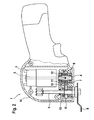
- Hand tool 1 shown has an electric drive motor 2, the armature 3 is fixedly connected to a coaxial drive shaft 4, which drives a driven or working shaft 5 with tool 6 arranged thereon.
- the rotational movement of the drive shaft 4 is converted into a rotary pendulum motion of the output shaft 5 and the tool 6 via an eccentric coupling device 7 with an angular deflection of usually a few degrees. This makes it possible to use the tool 6 both for grinding and for cutting or sawing a workpiece.
- the eccentric coupling 7 comprises a fixedly connected to the output shaft 5 coupling member, which is formed in the embodiment as a coupling fork 8, and a fixed to the drive shaft 4 connected eccentric, which is designed as an eccentric cam 9, which is rotationally fixed on the drive shaft 4.
- the eccentric cam 9 has a relation to the axis of rotation of the drive shaft 4 eccentric contour, at which a bent, the output shaft 5 facing away from section 8a the coupling fork 8 abuts, this section 8a includes the two prongs of the fork, which rest on opposite sides of the eccentric cam 9 and scan the cam contour.
- the axes of rotation of drive shaft 4 and output shaft 5 are perpendicular to each other, wherein the cranked portion 8a this angle offset is compensating by 90 ° bent.
- the mass balancing device 10 is designed analogously to the eccentric coupling device 7, but it generates an opposing compensating movement for compensating the imbalances generated by the eccentric coupling device.
- the mass balancing device 10 comprises a mass balancing member, which is designed as arranged on the output shaft 5 mass balancing fork 11, and an eccentric cam 12 which is fixedly mounted on the drive shaft 4.
- the mass balance fork 11 is rotatably supported on the output shaft 5 via a pivot bearing 13.
- the coupling fork 8 of the eccentric coupling 7 and the mass balance fork 11 is provided with a bent by 90 °, cranked portion 11 a, which includes the two prongs of the fork, the seated on the contour of the non-rotatably mounted on the drive shaft 4, associated eccentric cam 12th issue.
- the eccentric cam 12 of the mass balancing device 10 is expediently the same structure as the eccentric cam 9 of the eccentric coupling device 7, but arranged opposite to this rotated by 180 ° on the drive shaft 4.
- the shaft 4 with the bearings 9 and 12 at least without static imbalance and it must be provided no balance weight.
- a different geometry and / or mass of the eccentric cam 12 assigned to the mass balancing device can also be selected.
- the mass balance fork 11 of the mass balance device 10 is disposed adjacent to the end face of the output shaft 5, which faces away from the tool 6.
- the coupling fork 8 of the eccentric coupling device 7 is rotatably connected to the output shaft in a region between the rotary bearings of the output shaft 5 on the housing 14 of the power tool 1.
- the two eccentric cam 9 and 12 of the Exzenterkoppel coupled 7 and the mass balance device 10 are located directly behind one another lying on the drive shaft 4, wherein the eccentric cam 9 of the Exzenterkoppel responded 7 has a greater distance from the output shaft 5 than the eccentric cam 12 of the mass balance device 10.
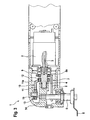
- Fig. 2 an alternative, special compact embodiment of the power tool 1 is shown.
- the tool 6, as in the previous embodiment, perform an oscillating rotary pendulum movement about the axis of rotation of the output shaft 5 in an angular range of plus / minus a few degrees.
- drive shaft 4 and output shaft 5 are arranged parallel to each other, which allows the small-sized design.
- the mass balancing device 10 is designed analogously to the eccentric coupling device 7 and comprises the mass balance fork 11, which is rotatably mounted on the output shaft 5 via the pivot bearing 13, and the associated eccentric cam 12 which is non-rotatably mounted on the drive shaft 4.
- the two forks 8 and 11 are directly parallel to each other, wherein the coupling fork 8 of the eccentric coupling device 7 is arranged closer to the tool 6 than the mass balance fork 11 of the mass balancing device 10. It is also possible a reverse arrangement in which the mass balance fork 11 is closer to the tool 6 as the coupling fork 8.
- Hand tool 1 shown are similar to the first embodiment, drive shaft 4 and output shaft 5 in a 90 ° angle to each other.
- the movement is in turn transmitted via an eccentric coupling device 7 with a bent coupling fork 8 and an eccentric cam 9, which is encompassed by the cranked section 8a of the coupling fork.
- the mass balance device 10 For vibration compensation, the mass balance device 10 is provided, which comprises the mass balance fork 11 with a cranked portion 11 a and eccentric cam 12 on the drive shaft 4.
- the mass balance fork 11 is not rotatably mounted on the output shaft 5, but on a separately formed therefrom balance shaft 15 via the pivot bearing 13.
- the balancing shaft 15 extends parallel with axial offset to the output shaft 5 and is located in the rear, the tool 6 opposite region of the power tool.
- the balance shaft 15 is fixedly received in the housing 14 or a housing cover of the power tool. If necessary, also comes with a version with separate Balancing shaft 15 into consideration, which is arranged coaxially with the output shaft 5.
- the mass balancing device 10 is not designed with a component to be acted upon rotationally, but has a translationally movable lifting mass part 16.
- This Hubmassenteil 16 is of the eccentric cam 12, which is part of the mass balancing device 10, translationally displaced in a housing-side slide guide, whereby the compensatory inertial forces are generated.
- the carriage guide for the Hubmassenteil 16 is located in a carriage guide member 17 which is connected to the housing 14 of the machine tool 1.
- the Hubmassenteil 16 can be moved in the carriage guide member 17 exclusively translationally displaceable, namely, based on the axis of rotation 18 of the drive motor 2 and the seated on the drive shaft 4 eccentric cam 12, in the transverse direction ,
- the Hubmassenteil 16 has a U-shaped recess 19, in which the eccentric cam 12 is added.
- the recess 19 can also be designed to be closed.
- the lifting mass portion 16 is translationally displaced back and forth in the transverse direction due to the eccentric contour. The mass forces occurring compensate for the imbalances generated by the eccentric coupling 7.
- the translational guidance takes place solely via the outer contour of the lift mass part 16 on assigned inner surfaces of the carriage guide part 17.
- the Hubmassenteil is enclosed by lateral walls 17a and 17b of the carriage guide part.
- a Hubmassenteil 16 is shown in a carriage guide member 17 in an alternative embodiment.
- the basic mode of operation corresponds to that of the previous exemplary embodiment, in which the lifting mass part 16 is displaced in a translatory manner within the slide guide part 17 by the eccentric cam 12.
- the guidance of the Hubmassenteils 16 in the carriage guide member 17 by means of a slide track 20 which is introduced into the Hubmassenteil 16, and a guide pin 21 which is fixedly connected to the carriage guide part 21.
Landscapes
- Engineering & Computer Science (AREA)
- Mechanical Engineering (AREA)
- Life Sciences & Earth Sciences (AREA)
- Wood Science & Technology (AREA)
- Forests & Forestry (AREA)
- Constituent Portions Of Griding Lathes, Driving, Sensing And Control (AREA)
- Auxiliary Devices For Machine Tools (AREA)
- Percussive Tools And Related Accessories (AREA)
- Finish Polishing, Edge Sharpening, And Grinding By Specific Grinding Devices (AREA)
Description
- Die Erfindung bezieht sich auf eine motorisch angetriebene Werkzeugmaschine mit einer von einer Antriebseinheit angetriebenen Antriebswelle und einer Abtriebswelle, auf der das Werkzeug aufgenommen ist, nach dem Oberbegriff des Anspruches 1.
- In der
DE 101 04 993 A1 wird eine Handwerkzeugmaschine zum Schleifen oder Polieren beschrieben, deren elektrischer Antriebsmotor über ein Getriebe einen Schleifteller beaufschlagt. In dem Getriebe ist eine Schaltvorrichtung enthalten, mittels der zumindest zwei Scheiftellerbewegungsarten wählbar sind. Zum einen soll ein Schwingschleifbetrieb realisiert werden, zum andern soll der Schleifteller eine ausschließliche rotatorische Bewegung zum Polieren eines Werkstücks durchführen können. Zur Realisierung des Schwingschleifbetriebs ist ein Exzenterantrieb vorgesehen, über den die Rotationsbewegung der Antriebswelle in eine exzentrische Bewegung des Schleiftellers umgesetzt wird. - Grundsätzlich können bei derartigen Schleifgeräten mit exzentrischem Antrieb Unwuchtschwingungen entstehen, die zu Komforteinbußen in der Handhabung der Werkzeugmaschine führen. Es ist darauf zu achten, dass die Schwingungen und Vibrationen ein zulässiges Maß nicht überschreiten.
- Aus der
EP 0 303 955 A1 ist eine Handschleifmaschine mit einem exzentrisch bewegtem Schleifteller bekannt, wobei zur Reduzierung von Schwingungen ein Massenausgleich an einer Abtriebswelle, welche Träger eines Schleiftellers ist, angeordnet ist. Die Abtriebswelle wird von einer Motorwelle angetrieben. Der Massenausgleich besteht aus einer Zusatzmasse, die fest mit der Abtriebswelle verbunden ist, sowie zwei Stellringen, die eine kreisrunde Kontur und eine exzentrische Bohrung aufweisen und an der Abtriebswelle drehbar gelagert sind. Je nach Winkellage der Stellringe können verschiedene Unwuchten ausgeglichen werden, wodurch es möglich ist, verschiedenartige Schleifteller einzusetzen und für die jeweiligen Schleifteller einen Massenausgleich vorzunehmen. - Der Massen- bzw. Schwingungsausgleich erfordert das Anbringen von mehreren Zusatzmassen, wodurch die Gesamtmasse der Abtriebswelle bzw. das Trägheitsmoment dieser Welle signifikant erhöht wird. Dementsprechend müssen höhere Kräfte bzw. Momente erzeugt und größer dimensionierte Antriebsmotoren eingesetzt werden, um die Abtriebswelle mit dem an der Abtriebswelle gehaltenen Schleifteller in eine Drehbewegung zu versetzen.
- Der Erfindung liegt die Aufgabe zugrunde, eine motorisch angetriebene Werkzeugmaschine, bei der die Drehbewegung der Antriebswelle über eine Exzenterkoppeleinrichtung auf die Abtriebswelle übertragbar ist, mit einfachen konstruktiven Maßnahmen schwingungsarm auszubilden.
- Diese Aufgabe wird erfindungsgemäß mit den Merkmalen des Anspruches 1 gelöst. Die Unteransprüche geben zweckmäßige Weiterbildungen an.
- Bei der erfindungsgemäßen, motorisch angetriebenen Werkzeugmaschine, bei der es sich insbesondere um eine Handwerkzeugmaschine handelt, ist die Drehbewegung der vom Antriebsmotor beaufschlagten Antriebswelle mithilfe einer Exzenterkoppeleinrichtung auf die Abtriebswelle übertragbar, auf der das Werkzeug aufgenommen ist. Zum Schwingungsausgleich ist eine Massenausgleichseinrichtung vorgesehen, die zumindest mit der Abtriebswelle in Wirkverbindung steht und eine der Exzenterkoppelbewegung entgegengerichtete Ausgleichsbewegung ausführt. Aufgrund dieses Schwingungsausgleichs ist die Vibrationsbelastung zumindest in einzelnen Betriebsphasen der Werkzeugmaschine deutlich reduziert, wobei gegebenenfalls auch eine Schwingungsreduzierung über den gesamten Betriebsbereich in Betracht kommt. Vorteilhafterweise sind die Schwingungen zumindest im Leerlauf der Werkzeugmaschine reduziert, gegebenenfalls aber auch im Arbeitsbetrieb.
- Die Reduzierung der Schwingungen wird dadurch erreicht, dass die Massenausgleichseinrichtung auf die Abtriebswelle einwirkt, und zwar in der Weise, dass die Massenausgleichseinrichtung eine zur Exzenterkoppelbewegung entgegengerichtete Ausgleichsbewegung ausübt. Diese Ausgleichsbewegung kompensiert die von der Exzenterkoppeleinrichtung erzeugten Drehschwingungen wenigstens teilweise. Da die Massenausgleichseinrichtung zumindest mit der Abtriebswelle in Wirkverbindung steht, werden Unwuchtschwingungen motornah kompensiert. Gegebenenfalls kommt aber auch eine Wirkverbindung der Massenausgleichseinrichtung mit der Abtriebswelle in Betracht, die Träger des Werkzeuges ist.
- Die Massenausgleichseinrichtung kann auf verschiedene Arten ausgeführt sein. Möglich ist eine Ausführung der Massenausgleichseinrichtung mit einem Massenausgleichsglied und einem Exzenterglied, das auf einer der Wellen sitzt, wobei das Massenausgleichsglied mit dem Exzenterglied in Wirkverbindung steht und insbesondere von diesem bewegt wird. Vorteilhafterweise ist die Exzenterkoppeleinrichtung analog hierzu aufgebaut und umfasst ein Koppelglied und ebenfalls ein Exzenterglied, das auf einer der Wellen sitzt, wobei das Koppelglied mit dem Exzenterglied in Wirkverbindung steht und von diesem in Bewegung versetzt wird. Die Massenausgleichseinrichtung und die Exzenterkoppeleinrichtung sind insbesondere parallel zueinander angeordnet, wobei vorteilhafterweise das Massenausgleichsglied und das Koppelglied parallel verlaufen und die Exzenterglieder beide auf der gleichen Welle, insbesondere der motorisch angetriebenen Antriebswelle aufsitzen. Die Exzenterglieder sind beispielsweise als Exzenternocken ausgebildet, die das jeweils zugeordnete Koppel- bzw. Massenausgleichsglied beaufschlagen, wobei Koppelglied und Massenausgleichsglied bevorzugt als Koppelgabel ausgeführt sind, deren Gabelzinken das jeweilige Exzenterglied umgreifen. Die Gabelzinken liegen an der Kontur des Exzenternockens an und werden durch die Exzenterbewegung des Nockens ausgelenkt, wobei diese Exzenterbewegung über das Koppelglied in eine Pendelbewegung der Abtriebswelle mit dem Werkzeug übertragen wird, die daraufhin eine rotatorische Pendelbewegung mit üblicherweise einem Winkelausschlag von in der Regel wenigen Grad ausführt. Aufgrund der bauähnlichen Ausführung der Massenausgleichseinrichtung führt das Massenausgleichsglied eine entsprechende Bewegung aus, die jedoch der Exzenterkoppelbewegung entgegengerichtet ist. Zweckmäßigerweise sind die beiden Exzenternocken bezogen auf die Drehachse der Welle um 180° zueinander versetzt.
- Für die Bewegungsübertragung der Rotation der Antriebswelle auf die Abtriebswelle mithilfe der Exzenterkoppeleinrichtung ist das Koppelglied bevorzugt auf der Abtriebswelle angeordnet, so dass jede Drehbewegung des Koppelgliedes, ausgelöst durch die Bewegung der Antriebswelle und die Übertragung über den Exzenternocken, zu der gewünschten Pendelbewegung führt. Für die Anordnung des Massenausgleichsglieds kommen dagegen verschiedene Ausführungen in Betracht. Gemäß einer ersten vorteilhaften Realisierung ist das Massenausgleichsglied ebenfalls auf der Abtriebswelle gehalten, wobei in diesem Fall das Massenausgleichsglied drehbar auf der Abtriebswelle gelagert ist, so dass eine entgegengerichtete Bewegung des Massenausgleichsglieds zum Koppelglied möglich ist. Gemäß einer zweiten vorteilhaften Realisierung ist dagegen das Massenausgleichsglied auf einer separat ausgebildeten Ausgleichswelle gelagert, die entweder koaxial zur Abtriebswelle oder parallel versetzt zu dieser angeordnet ist und insbesondere am Gehäuse der Werkzeugmaschine gehalten ist. Die Schwingungskompensation erfolgt über die Einwirkung der Massenausgleichseinrichtung auf die Antriebswelle.
- Die erfindungsgemäße Werkzeugmaschine kann entweder eine winklig zueinander angeordnete Antriebwelle und Abtriebswelle aufweisen, wobei in diesem Fall das Koppelglied der Exzenterkoppeleinrichtung und das Massenausgleichsglied der Massenausgleichseinrichtung vorteilhaft einen abgekröpften Kontaktabschnitt aufweisen, der in Kontakt mit dem jeweiligen Exzenterglied steht. In Betracht kommt aber auch eine parallele Anordnung von Antriebs- und Abtriebswelle, wodurch eine besondere kompakte Ausführung realisiert werden kann. Außerdem ist bei paralleler Anordnung der Wellen ein geradlinig ausgeführtes Koppel- bzw. Massenausgleichsglied ohne abgekröpften Abschnitt möglich.
- Des Weiteren ist es vorteilhaft, den Abstand zwischen dem Massenausgleichsglied und dem zugeordneten Exzenterglied geringer auszuführen als den Abstand zwischen dem Koppelglied und dem diesem zugeordneten Exzenterglied. Dies hat zur Folge, dass das kürzer ausgebildete Massenausgleichsglied bei gleicher Exzentrizität der beiden Exzenterglieder eine höhere Winkelbeschleunigung erfährt als das Koppelglied, so dass zum Drehmassenausgleich das Massenausgleichsglied eine geringere Massenträgheit benötigt. Hierdurch wird ein weiterer Bauraumvorteil erzielt. Diese Ausführung eignet sich insbesondere für winklig zueinander stehende Wellen.
- Gemäß einer weiteren zweckmäßigen Ausführung ist die Massenausgleichseinrichtung als Hubmassenteil ausgebildet, das in einer gehäuseseitigen Schlittenführung verschieblich gelagert und von dem Exzenterglied beaufschlagbar ist. Im Gegensatz zu den vorgenannten Ausführungen der Massenausgleichseinrichtung, bei denen das Massenausgleichsglied eine ausgleichende Drehbewegung ausführt, ist bei dieser Variante eine vorzugsweise translatorische Verschiebebewegung des Hubmassenteils vorgesehen, die zum Unwuchtausgleich führt. Die Schlittenführung ermöglicht eine Verschiebebewegung des Hubmassenteils gegenüber dem Gehäuse, wobei die Schlittenführung beispielsweise als Kulissenführung mit einem darin geführten Kulissenstift ausgebildet ist.
- Weitere Vorteile und zweckmäßige Ausführungen sind den weiteren Ansprüchen, der Figurenbeschreibung und den Zeichnungen zu entnehmen. Es zeigen:
- Fig. 1
- eine Handwerkzeugmaschine, deren Werkzeug eine oszillierende Dreh- bzw. Pendelschwingung zum Sägen und Schleifen ausübt, wobei das Werkzeug an einer Abtriebswelle gehalten ist, die senkrecht zu einer motorisch angetriebenen Antriebswelle steht, deren Drehbewegung über eine Exzenterkoppeleinrichtung auf die Abtriebswelle übertragbar ist, und wobei eine Massenausgleichseinrichtung zur Kompensation von Unwuchtschwingungen vorgesehen ist,
- Fig. 2
- ein weiteres Ausführungsbeispiel eines handgeführten Werkzeugs zum Schleifen und Sägen, wobei die Abtriebswelle parallel zur Antriebswelle angeordnet ist,
- Fig. 3
- ein weiteres Ausführungsbeispiel, bei dem die Massenausgleichseinrichtung ein drehbar gelagertes Massenausgleichsglied umfasst, das an einer separat ausgebildeten Ausgleichswelle gelagert ist,
- Fig. 4
- ein weiteres Ausführungsbeispiel einer Handwerkzeugmaschine zum Schleifen und Sägen, bei dem die Massenausgleichseinrichtung ein Hubmassenteil umfasst, das in einer gehäuseseitigen Schlittenführung verschieblich gelagert ist,
- Fig. 5
- eine Einzeldarstellung der Schlittenführung aus
Fig. 4 , - Fig. 6
- die Schlittenführung einschließlich des verschieblich gelagerten Hubmassenteils, das von einem Exzenterglied in der Schlittenführung hin und her bewegt wird,
- Fig. 7 und Fig. 8
- eine weitere Massenausgleichseinrichtung mit einem in einer Schlittenführung verschieblich gelagerten Hubmassenteil.
- In den Figuren sind gleiche Bauteile mit gleichen Bezugszeichen versehen.
- Die in
Fig. 1 dargestellte Handwerkzeugmaschine 1 weist einen elektrischen Antriebsmotor 2 auf, dessen Anker 3 fest mit einer koaxialen Antriebswelle 4 verbunden ist, die eine Abtriebs- bzw. Arbeitswelle 5 mit daran angeordnetem Werkzeug 6 antreibt. Bei Betätigung des elektrischen Antriebsmotors 2 wird über eine Exzenterkoppeleinrichtung 7 die Drehbewegung der Antriebswelle 4 in eine Drehpendelbewegung der Abtriebswelle 5 und des Werkzeuges 6 umgesetzt mit einem Winkelausschlag von üblicherweise wenigen Grad. Hierdurch besteht die Möglichkeit, das Werkzeug 6 sowohl zum Schleifen als auch zum Schneiden bzw. Sägen eines Werkstücks einzusetzen. - Die Exzenterkoppeleinrichtung 7 umfasst ein mit der Abtriebwelle 5 fest verbundenes Koppelglied, das im Ausführungsbeispiel als Koppelgabel 8 ausgebildet ist, sowie ein fest mit der Antriebswelle 4 verbundenes Exzenterglied, das als Exzenternocken 9 ausgeführt ist, welcher auf der Antriebswelle 4 drehfest aufsitzt. Der Exzenternocken 9 besitzt eine bezogen auf die Drehachse der Antriebswelle 4 exzentrische Kontur, an der ein abgekröpfter, der Abtriebswelle 5 abgewandter Abschnitt 8a der Koppelgabel 8 anliegt, wobei dieser Abschnitt 8a die beiden Zinken der Gabel umfasst, die an gegenüberliegenden Seiten des Exzenternockens 9 anliegen und die Nockenkontur abtasten. Die Drehachsen von Antriebswelle 4 und Abtriebswelle 5 liegen senkrecht zueinander, wobei der abgekröpfte Abschnitt 8a diesen Winkelversatz ausgleichend um 90° abgebogen ist.
- Bei der Bewegungsübertragung der Drehbewegung der Antriebswelle 4 auf die Abtriebswelle 5 mittels der Exzenterkoppeleinrichtung 7 entsteht eine Massenunwucht, zu deren Ausgleich eine Massenausgleichseinrichtung 10 vorgesehen ist, die ebenfalls zwischen Antriebswelle 4 und Abtriebswelle 5 angeordnet ist. Die Massenausgleichseinrichtung 10 ist analog zur Exzenterkoppeleinrichtung 7 ausgebildet, sie erzeugt jedoch eine entgegengerichtete Ausgleichsbewegung zur Kompensation der von der Exzenterkoppeleinrichtung erzeugten Unwuchten. Die Massenausgleichseinrichtung 10 umfasst ein Massenausgleichsglied, das als auf der Abtriebswelle 5 angeordnete Massenausgleichsgabel 11 ausgebildet ist, sowie einen Exzenternocken 12, der fest auf der Antriebwelle 4 aufsitzt. Die Massenausgleichsgabel 11 ist über ein Drehlager 13 drehbar auf der Abtriebswelle 5 gelagert. Entsprechend der gabelförmigen Ausführung der Koppelgabel 8 der Exzenterkoppeleinrichtung 7 ist auch die Massenausgleichsgabel 11 mit einem um 90° umgebogenen, abgekröpften Abschnitt 11a versehen, der die beiden Zinken der Gabel umfasst, die an der Kontur des drehfest an der Antriebswelle 4 aufsitzenden, zugeordneten Exzenternockens 12 anliegen. Der Exzenternocken 12 der Massenausgleichseinrichtung 10 ist zweckmäßigerweise gleich aufgebaut wie der Exzenternocken 9 der Exzenterkoppeleinrichtung 7, jedoch gegenüber diesem um 180° verdreht auf der Antriebswelle 4 angeordnet. Hierdurch ist die Welle 4 mit den Lagern 9 und 12 zumindest ohne statische Unwucht und es muss kein Ausgleichsgewicht vorgesehen werden. Gegebenenfalls kann auch eine abweichende Geometrie und/oder Masse des der Massenausgleichseinrichtung zugeordneten Exzenternockens 12 gewählt werden.
- Die Massenausgleichsgabel 11 der Massenausgleichseinrichtung 10 ist benachbart zur Stirnseite der Abtriebswelle 5 angeordnet, die dem Werkzeug 6 abgewandt ist. Die Koppelgabel 8 der Exzenterkoppeleinrichtung 7 ist in einem Bereich zwischen den Drehlagern der Abtriebswelle 5 am Gehäuse 14 der Handwerkzeugmaschine 1 drehfest mit der Abtriebswelle verbunden. Die beiden Exzenternocken 9 und 12 der Exzenterkoppeleinrichtung 7 bzw. der Massenausgleichseinrichtung 10 befinden sich unmittelbar hintereinander liegend auf der Antriebswelle 4, wobei der Exzenternocken 9 der Exzenterkoppeleinrichtung 7 einen größeren Abstand zur Abtriebswelle 5 aufweist als der Exzenternocken 12 der Massenausgleichseinrichtung 10. Dies hat zur Folge, dass aufgrund der gleichartigen Kontur der beiden Exzenternocken 9 bzw. 12 die Massenausgleichsgabel 11 eine größere Winkelbeschleunigung erfährt als die Koppelgabel 8 der Exzenterkoppeleinrichtung 7, wodurch die geringere Masse der kürzeren Massenausgleichsgabel 11 gegenüber der Koppelgabel 8 zumindest teilweise kompensiert werden kann.
- In
Fig. 2 ist eine alternative, besondere kompakte Ausführung der Handwerkzeugmaschine 1 dargestellt. Das Werkzeug 6 kann wie beim vorherigen Ausführungsbeispiel eine oszillierende Drehpendelbewegung um die Drehachse der Abtriebswelle 5 in einem Winkelbereich von plus/minus wenigen Grad ausführen. Im Unterschied zum vorhergehenden Ausführungsbeispiel sind jedoch Antriebswelle 4 und Abtriebswelle 5 parallel zueinander angeordnet, was die klein bauende Ausführung ermöglicht. - Die Bewegungsübertragung zwischen Antriebswelle 4 und Abtriebswelle 5 erfolgt über die Exzenterkoppeleinrichtung 7, die die drehfest mit der Abtriebswelle 5 verbundene Koppelgabel 8 und den drehfest auf der Antriebswelle 4 aufsitzenden Exzenternocken 9 umfasst. Aufgrund der parallelen Anordnung von Antriebswelle 4 und Abtriebswelle 5 ist die Koppelgabel 8 geradlinig ausgeführt; ein abgekröpfter Abschnitt ist im Unterschied zum vorhergehenden Ausführungsbeispiel nicht erforderlich.
- Die Massenausgleichseinrichtung 10 ist analog zur Exzenterkoppeleinrichtung 7 ausgeführt und umfasst die Massenausgleichsgabel 11, die über das Drehlager 13 drehbar auf der Abtriebswelle 5 gelagert ist, sowie den zugeordneten Exzenternocken 12, der drehfest auf der Antriebswelle 4 aufsitzt. Die beiden Gabeln 8 und 11 liegen unmittelbar parallel zueinander, wobei die Koppelgabel 8 der Exzenterkoppeleinrichtung 7 näher am Werkzeug 6 angeordnet ist als die Massenausgleichsgabel 11 der Massenausgleichseinrichtung 10. Möglich ist aber auch eine umgekehrte Anordnung, bei der die Massenausgleichsgabel 11 näher am Werkzeug 6 liegt als die Koppelgabel 8.
- Bei der in
Fig. 3 dargestellten Handwerkzeugmaschine 1 liegen ähnlich wie im ersten Ausführungsbeispiel Antriebswelle 4 und Abtriebswelle 5 in einem 90°-Winkel zueinander. Die Bewegungsübertragung erfolgt wiederum über eine Exzenterkoppeleinrichtung 7 mit abgekröpfter Koppelgabel 8 und einem Exzenternocken 9, der von dem abgekröpften Abschnitt 8a der Koppelgabel umgriffen wird. - Zum Schwingungsausgleich ist die Massenausgleichseinrichtung 10 vorgesehen, die die Massenausgleichsgabel 11 mit abgekröpftem Abschnitt 11a und Exzenternocken 12 auf der Antriebswelle 4 umfasst. Im Unterschied zum ersten Ausführungsbeispiel ist jedoch die Massenausgleichsgabel 11 nicht an der Abtriebswelle 5, sondern an einer separat hiervon ausgebildeten Ausgleichswelle 15 über das Drehlager 13 drehbar gelagert. Die Ausgleichswelle 15 verläuft parallel mit axialem Versatz zur Abtriebswelle 5 und befindet sich im hinteren, dem Werkzeug 6 gegenüberliegenden Bereich der Handwerkzeugmaschine. Die Ausgleichswelle 15 ist fest im Gehäuse 14 bzw. einem Gehäusedeckel der Handwerkzeugmaschine aufgenommen. Gegebenenfalls kommt auch eine Ausführung mit separater Ausgleichswelle 15 in Betracht, die koaxial zur Abtriebswelle 5 angeordnet ist.
- Im Ausführungsbeispiel gemäß
Fig. 4 sind Antriebswelle 4 und Abtriebswelle 5 senkrecht zueinander angeordnet, wobei zur Bewegungsübertragung die Exzenterkoppeleinrichtung 7 mit Koppelgabel 8 und Exzenternocken 9 vorgesehen ist. Die Massenausgleichseinrichtung 10 ist in diesem Fall im Unterschied zu den vorhergehenden Ausführungsbeispielen nicht mit einem rotatorisch zu beaufschlagenden Bauteil ausgeführt, sondern weist ein translatorisch bewegbares Hubmassenteil 16 auf. Dieses Hubmassenteil 16 wird von dem Exzenternocken 12, welcher Bestandteil der Massenausgleichseinrichtung 10 ist, in einer gehäuseseitigen Schlittenführung translatorisch verschoben, wodurch die ausgleichenden Massenkräfte erzeugt werden. Die Schlittenführung für das Hubmassenteil 16 befindet sich in einem Schlittenführungsteil 17, das mit dem Gehäuse 14 der Werkzeugmaschine 1 verbunden ist. - In den
Figuren 5 und 6 findet sich eine Einzeldarstellung des Schlittenführungsteils 17 mit darin aufgenommenem Hubmassenteil 16. Das Hubmassenteil 16 kann in dem Schlittenführungsteil 17 ausschließlich translatorisch verschieblich bewegt werden, und zwar, bezogen auf die Drehachse 18 des Antriebsmotors 2 sowie des auf der Antriebswelle 4 aufsitzenden Exzenternockens 12, in Querrichtung. WieFig. 6 zu entnehmen, besitzt das Hubmassenteil 16 eine U-förmige Ausnehmung 19, in der der Exzenternocken 12 aufgenommen ist. Die Ausnehmung 19 kann aber gegebenenfalls auch geschlossen ausgeführt sein. Beim Umlauf des Exzenternockens 12 wird aufgrund der exzentrischen Kontur des Exzenternockens 12 das Hubmassenteil 16 in Querrichtung translatorisch hin und her verschoben. Die dabei auftretenden Massenkräfte wirken kompensierend zu den Unwuchten, die von der Exzenterkoppeleinrichtung 7 erzeugt werden. Die translatorische Führung erfolgt allein über die Außenkontur des Hubmassenteils 16 an zugeordneten Innenflächen des Schlittenführungsteils 17. Zur Begrenzung der Bewegung des Hubmassenteils 16 in Achsrichtung der Drehachse 18 der Antriebswelle 4 ist das Hubmassenteil von seitlichen Wandungen 17a und 17b des Schlittenführungsteils eingeschlossen. - Im Ausführungsbeispiel gemäß den
Figuren 7 und 8 ist ein Hubmassenteil 16 in einem Schlittenführungsteil 17 in einer alternativen Ausführung dargestellt. Die grundsätzliche Funktionsweise entspricht derjenigen des vorhergehenden Ausführungsbeispiels, in dem das Hubmassenteil 16 innerhalb des Schlittenführungsteils 17 translatorisch von dem Exzenternocken 12 hin und her verschoben wird. Allerdings erfolgt die Führung des Hubmassenteils 16 im Schlittenführungsteil 17 mithilfe einer Kulissenbahn 20, die in das Hubmassenteil 16 eingebracht ist, sowie einem Führungsstift 21 der fest mit dem Schlittenführungsteil 21 verbunden ist. Es sind zwei Kulissenbahnen 20 mit jeweils einragendem Führungsstift 21 vorgesehen.
Claims (15)
- Motorisch angetriebene Werkzeugmaschine, insbesondere Handwerkzeugmaschine (1) mit drehbar anzutreibendem Werkzeug (6), mit einer von einer Antriebseinheit (2) angetriebenen Antriebswelle (4) und einer Abtriebswelle (5), auf der das Werkzeug (6) aufgenommen ist, wobei die Drehbewegung der Antriebswelle (4) über eine Exzenterkoppeleinrichtung (7) auf die Abtriebswelle (5) übertragbar ist, wobei zum Schwingungsausgleich eine Massenausgleichseinrichtung (10) vorgesehen ist, die mit zumindest einer der Wellen (4, 5) in Wirkverbindung steht und eine der Exzenterkoppelbewegung entgegengerichtete Ausgleichsbewegung ausführt,
dadurch gekennzeichnet, dass die Massenausgleichseinrichtung (10) ein Massenausgleichsglied (11) und ein Exzenterglied (12) umfasst, wobei das Massenausgleichsglied (11) mit dem Exzenterglied (12) in Wirkverbindung steht,
dass die Exzenterkoppeleinrichtung (7) ein Koppelglied (8) und ein Exzenterglied (9) umfasst, wobei das Koppelglied (8) mit dem Exzenterglied (9) in Wirkverbindung steht.
dass die Exzenterglieder als fest mit der Antriebswelle (4) verbundene Exzenternocken (9, 12) ausgebildet sind und dass das Koppelglied (8) bzw. das Massenausgleichsglied (11) an der Kontur der zugeordneten Exzenternocken (9, 12) anliegen. - Werkzeugmaschine nach Anspruch 1,
dadurch gekennzeichnet, dass ein Bauteil (11) der Massenausgleichseinrichtung (10) drehbar auf der Abtriebswelle (5) gelagert ist. - Werkzeugmaschine nach Anspruch 1 oder 2,
dadurch gekennzeichnet, dass ein Bauteil (11) der Massenausgleichseinrichtung (10) auf einer separat ausgebildeten Ausgleichswelle (15) gelagert ist. - Werkzeugmaschine nach Anspruch 3,
dadurch gekennzeichnet, dass die Ausgleichswelle (15) am Gehäuse (14) der Werkzeugmaschine (1) gehalten ist. - Werkzeugmaschine nach Anspruch 4,
dadurch gekennzeichnet, dass die Ausgleichswelle (15) parallel versetzt zur Abtriebswelle (5) angeordnet ist. - Werkzeugmaschine nach einem der Ansprüche 1 bis 5,
dadurch gekennzeichnet, dass die Exzenternocken (9, 12) bezogen auf die Drehachse (18) der Antriebswelle (4) um 180° zueinander versetzt sind. - Werkzeugmaschine nach einem der Ansprüche 1 bis 6,
dadurch gekennzeichnet, dass das Koppelglied (8) und das Massenausgleichsglied (11) jeweils gabelförmig ausgeführt sind, wobei die Gabelzinken das jeweilige Exzenterglied (9, 12) umgreifen. - Werkzeugmaschine nach einem der Ansprüche 1 bis 7,
dadurch gekennzeichnet, dass der Abstand zwischen dem Massenausgleichsglied (11) und dem zugeordneten Exzenterglied (12) geringer ist als der Abstand zwischen dem Koppelglied (8) und dem zugeordneten Exzenterglied (9). - Werkzeugmaschine nach einem der Ansprüche 1 bis 8,
dadurch gekennzeichnet, dass Antriebs- und Abtriebswelle (4, 5) winklig zueinander angeordnet sind. - Werkzeugmaschine nach Anspruch 9,
dadurch gekennzeichnet, dass das Koppelglied (8) und das Massenausgleichsglied (11) jeweils einen abgekröpften Kontaktabschnitt (8a, 11a) aufweisen, der in Kontakt mit dem jeweiligen Exzenterglied (9, 12) steht. - Werkzeugmaschine nach nach einem der Ansprüche 1 bis 10,
dadurch gekennzeichnet, dass Antriebs- und Abtriebswelle (4, 5) parallel zueinander angeordnet sind. - Werkzeugmaschine nach einem der Ansprüche 1 bis 11, dadurch gekennzeichnet, dass die Exzenterkoppeleinrichtung (7) zwischen dem Werkzeug (6) und der Massenausgleichseinrichtung (10) auf der Abtriebswelle (5) gehalten ist.
- Werkzeugmaschine nach einem der Ansprüche 1 bis 12, dadurch gekennzeichnet, dass die Massenausgleichseinrichtung (10) ein Hubmassenteil (16) umfasst, das in einer Schlittenführung (17) verschieblich gelagert und von dem Exzenterglied (12) beaufschlagt ist.
- Werkzeugmaschine nach Anspruch 13,
dadurch gekennzeichnet, dass die Schlittenführung (17) eine ausschließlich translatorische Verschiebebewegung des Hubmassenteils (16) ermöglicht. - Werkzeugmaschine nach Anspruch 13 oder 14,
dadurch gekennzeichnet, dass die Schlittenführung (17) eine Kulissenführung mit einer Kulissenbahn (20) und einem darin geführten Führungsstift (21) umfasst.
Applications Claiming Priority (2)
| Application Number | Priority Date | Filing Date | Title |
|---|---|---|---|
| DE102007018466A DE102007018466A1 (de) | 2007-04-19 | 2007-04-19 | Motorisch angetriebene Werkzeugmaschine |
| PCT/EP2008/052053 WO2008128804A1 (de) | 2007-04-19 | 2008-02-20 | Motorisch angetriebene werkzeugmaschine |
Publications (2)
| Publication Number | Publication Date |
|---|---|
| EP2150376A1 EP2150376A1 (de) | 2010-02-10 |
| EP2150376B1 true EP2150376B1 (de) | 2014-10-15 |
Family
ID=39276369
Family Applications (1)
| Application Number | Title | Priority Date | Filing Date |
|---|---|---|---|
| EP08709130.2A Active EP2150376B1 (de) | 2007-04-19 | 2008-02-20 | Motorisch angetriebene werkzeugmaschine |
Country Status (5)
| Country | Link |
|---|---|
| US (1) | US8162727B2 (de) |
| EP (1) | EP2150376B1 (de) |
| CN (1) | CN101663130B (de) |
| DE (1) | DE102007018466A1 (de) |
| WO (1) | WO2008128804A1 (de) |
Families Citing this family (27)
| Publication number | Priority date | Publication date | Assignee | Title |
|---|---|---|---|---|
| DE102008004638A1 (de) * | 2008-01-16 | 2009-07-23 | Robert Bosch Gmbh | Motorisch angetriebene Werkzeugmaschine |
| DE102009014970A1 (de) | 2009-03-18 | 2010-09-23 | C. & E. Fein Gmbh | Oszillationswerkzeug mit Vibrationsdämpfung |
| DE202009011312U1 (de) | 2009-08-11 | 2010-12-23 | C. & E. Fein Gmbh | Handwerkzeug mit einem Oszillationsantrieb |
| DE102010027205A1 (de) | 2010-07-06 | 2012-01-12 | C. & E. Fein Gmbh | Handwerkzeug |
| DE102010039787A1 (de) * | 2010-08-26 | 2012-03-01 | Robert Bosch Gmbh | Handwerkzeugmaschine |
| DE102010039786A1 (de) * | 2010-08-26 | 2012-03-01 | Robert Bosch Gmbh | System mit zumindest zwei Oszillationseinsatzwerkzeugen |
| DE102010046629A1 (de) | 2010-09-17 | 2012-03-22 | C. & E. Fein Gmbh | Handwerkzeug |
| DE102010043188A1 (de) * | 2010-10-29 | 2012-05-03 | Robert Bosch Gmbh | Ablaufsicherungsvorrichtung |
| DE102011015117A1 (de) * | 2011-03-22 | 2012-09-27 | C. & E. Fein Gmbh | Handwerkzeug |
| MX2013012159A (es) * | 2011-04-21 | 2014-06-23 | Infusion Brands Inc | Sierra con multiples herramientas de doble oscilacion. |
| EP2556922B1 (de) * | 2011-08-09 | 2014-03-19 | C. & E. Fein GmbH | Kraftgetriebenes Handwerkzeug |
| JP2013059820A (ja) * | 2011-09-12 | 2013-04-04 | Makita Corp | 電動工具 |
| JP2013169623A (ja) * | 2012-02-21 | 2013-09-02 | Makita Corp | 作業工具 |
| JP5852901B2 (ja) * | 2012-02-24 | 2016-02-03 | 株式会社マキタ | 往復回転式電動工具 |
| CN103567842B (zh) * | 2012-08-07 | 2017-02-08 | 苏州宝时得电动工具有限公司 | 磨削动力工具 |
| DE102013104271A1 (de) * | 2013-04-26 | 2014-10-30 | C. & E. Fein Gmbh | Werkzeugmaschine |
| CN104669218B (zh) * | 2013-11-29 | 2016-10-12 | 苏州宝时得电动工具有限公司 | 摆动动力工具 |
| DE102013225885A1 (de) * | 2013-12-13 | 2015-06-18 | Robert Bosch Gmbh | Batteriebetriebener Exzenterschleifer mit einer wiederaufladbaren Batterie |
| JP6262605B2 (ja) * | 2014-06-05 | 2018-01-17 | 株式会社マキタ | 作業工具 |
| DE102014212794A1 (de) * | 2014-07-02 | 2016-01-07 | Robert Bosch Gmbh | Oszillationsantriebsvorrichtung |
| JP2016087725A (ja) * | 2014-10-31 | 2016-05-23 | 日立工機株式会社 | 往復動工具 |
| CN105835012B (zh) * | 2015-02-02 | 2020-08-21 | 株式会社牧田 | 作业工具 |
| JP6403589B2 (ja) * | 2015-02-02 | 2018-10-10 | 株式会社マキタ | 作業工具 |
| JP6621641B2 (ja) * | 2015-10-15 | 2019-12-18 | 株式会社マキタ | 電動工具 |
| CN107538439B (zh) * | 2016-06-29 | 2023-09-12 | 苏州宝时得电动工具有限公司 | 摆动机减振系统和方法以及具有该减振系统的摆动机 |
| CN110722607B (zh) * | 2019-10-18 | 2021-08-31 | 苏州劲山电动工具有限公司 | 一种平衡手持式工具高频摆动机构振动的结构 |
| CN217943243U (zh) * | 2021-03-30 | 2022-12-02 | 创科无线普通合伙 | 振荡手持式电动工具 |
Family Cites Families (11)
| Publication number | Priority date | Publication date | Assignee | Title |
|---|---|---|---|---|
| US2367668A (en) * | 1942-12-11 | 1945-01-23 | Roy J Champayne | Rubbing machine |
| US3482362A (en) * | 1966-01-28 | 1969-12-09 | Ingersoll Rand Co | Double acting sander head |
| DE3517766A1 (de) * | 1984-09-08 | 1986-03-20 | Licentia Patent-Verwaltungs-Gmbh, 6000 Frankfurt | Schwingschleifer |
| DE3518984A1 (de) * | 1985-05-25 | 1986-11-27 | Festo KG, 7300 Esslingen | Ausgewuchteter schwingschleifer |
| DE3727487A1 (de) * | 1987-08-18 | 1989-03-02 | Miksa Marton | Handschleifmaschine |
| DE4233729A1 (de) * | 1992-10-07 | 1994-04-14 | Bosch Gmbh Robert | Exzentertellerschleifer mit Schleiftellerbremse |
| DE4233727A1 (de) * | 1992-10-07 | 1994-04-14 | Bosch Gmbh Robert | Exzentertellerschleifer |
| DE4344849A1 (de) * | 1993-12-29 | 1995-07-06 | Fein C & E | Werkzeugmaschine |
| DE10104993A1 (de) | 2001-02-03 | 2002-08-22 | Bosch Gmbh Robert | Handwerkzeugmaschine zum Schleifen, Polieren oder dergleichen |
| GB2393934A (en) * | 2002-10-07 | 2004-04-14 | Black & Decker Inc | A reciprocating saw with two eccentrics |
| DE10260213A1 (de) * | 2002-12-13 | 2004-06-24 | C. & E. Fein Gmbh | Oszillationsantrieb |
-
2007
- 2007-04-19 DE DE102007018466A patent/DE102007018466A1/de not_active Withdrawn
-
2008
- 2008-02-20 US US12/374,537 patent/US8162727B2/en active Active
- 2008-02-20 CN CN2008800126500A patent/CN101663130B/zh active Active
- 2008-02-20 EP EP08709130.2A patent/EP2150376B1/de active Active
- 2008-02-20 WO PCT/EP2008/052053 patent/WO2008128804A1/de active Application Filing
Also Published As
| Publication number | Publication date |
|---|---|
| DE102007018466A1 (de) | 2008-10-23 |
| US8162727B2 (en) | 2012-04-24 |
| EP2150376A1 (de) | 2010-02-10 |
| CN101663130A (zh) | 2010-03-03 |
| CN101663130B (zh) | 2013-02-13 |
| WO2008128804A1 (de) | 2008-10-30 |
| US20090311952A1 (en) | 2009-12-17 |
Similar Documents
| Publication | Publication Date | Title |
|---|---|---|
| EP2150376B1 (de) | Motorisch angetriebene werkzeugmaschine | |
| EP2242613B1 (de) | Motorisch angetriebene werkzeugmaschine | |
| EP2139647B1 (de) | Motorisch angetriebene werkzeugmaschine | |
| EP2139654B1 (de) | Motorisch angetriebene werkzeugmaschine | |
| EP1360032B1 (de) | Handwerkzeugmaschine zum schliefen, polieren oder dergleichen | |
| EP2436485A2 (de) | Handwerkzeug | |
| EP2796247B1 (de) | Werkzeugmaschine | |
| EP2366493B1 (de) | Hand-Werkzeugmaschine mit einem Drehwinkel-Führungsmittel aufweisenden Exzentergetriebe | |
| EP3638457B1 (de) | Handwerkzeugmaschine | |
| EP2342050B1 (de) | Handwerkzeugmaschine mit einem schaltbaren getriebe | |
| EP2191939B1 (de) | Handwerkzeugmaschinenvorrichtung | |
| WO2016037898A1 (de) | Antrieb einer maschine, drehmomentmotor, kupplungseinrichtung, vorrichtung zum bearbeiten von werkstoffen und verwendung eines torquemotors | |
| WO2012025329A1 (de) | Handwerkzeugmaschine | |
| EP1633533B1 (de) | Elektrohandwerkzeugmaschine | |
| EP2938442B1 (de) | Schwingungserreger für lenkbare bodenverdichtungsvorrichtungen | |
| WO2011160147A2 (de) | Schmiedevorrichtung | |
| EP2668006B1 (de) | Werkzeugspannvorrichtung | |
| EP2027972B1 (de) | Handwerkzeugmaschine mit Hubantrieb | |
| EP2681021A1 (de) | Werkzeugmaschinensystem | |
| DE3028464A1 (de) | Tragbares schlagwerkzeug | |
| EP4353417A1 (de) | Mobile werkzeugmaschine mit zuschaltbarer oder permanenter hemmstufe | |
| WO2012084349A1 (de) | Handwerkzeugmaschine | |
| WO2014101977A1 (de) | Schwingungserreger für bodenverdichtungsvorrichtungen | |
| DE102013212714A1 (de) | Handwerkzeugmaschinenantriebsvorrichtung |
Legal Events
| Date | Code | Title | Description |
|---|---|---|---|
| PUAI | Public reference made under article 153(3) epc to a published international application that has entered the european phase |
Free format text: ORIGINAL CODE: 0009012 |
|
| 17P | Request for examination filed |
Effective date: 20091119 |
|
| AK | Designated contracting states |
Kind code of ref document: A1 Designated state(s): AT BE BG CH CY CZ DE DK EE ES FI FR GB GR HR HU IE IS IT LI LT LU LV MC MT NL NO PL PT RO SE SI SK TR |
|
| AX | Request for extension of the european patent |
Extension state: AL BA MK RS |
|
| 17Q | First examination report despatched |
Effective date: 20100212 |
|
| DAX | Request for extension of the european patent (deleted) | ||
| GRAP | Despatch of communication of intention to grant a patent |
Free format text: ORIGINAL CODE: EPIDOSNIGR1 |
|
| INTG | Intention to grant announced |
Effective date: 20140703 |
|
| GRAS | Grant fee paid |
Free format text: ORIGINAL CODE: EPIDOSNIGR3 |
|
| GRAA | (expected) grant |
Free format text: ORIGINAL CODE: 0009210 |
|
| AK | Designated contracting states |
Kind code of ref document: B1 Designated state(s): AT BE BG CH CY CZ DE DK EE ES FI FR GB GR HR HU IE IS IT LI LT LU LV MC MT NL NO PL PT RO SE SI SK TR |
|
| REG | Reference to a national code |
Ref country code: CH Ref legal event code: EP Ref country code: GB Ref legal event code: FG4D Free format text: NOT ENGLISH |
|
| REG | Reference to a national code |
Ref country code: IE Ref legal event code: FG4D Free format text: LANGUAGE OF EP DOCUMENT: GERMAN |
|
| REG | Reference to a national code |
Ref country code: AT Ref legal event code: REF Ref document number: 691417 Country of ref document: AT Kind code of ref document: T Effective date: 20141115 |
|
| REG | Reference to a national code |
Ref country code: DE Ref legal event code: R096 Ref document number: 502008012318 Country of ref document: DE Effective date: 20141127 |
|
| REG | Reference to a national code |
Ref country code: NL Ref legal event code: VDEP Effective date: 20141015 |
|
| REG | Reference to a national code |
Ref country code: LT Ref legal event code: MG4D |
|
| PG25 | Lapsed in a contracting state [announced via postgrant information from national office to epo] |
Ref country code: NL Free format text: LAPSE BECAUSE OF FAILURE TO SUBMIT A TRANSLATION OF THE DESCRIPTION OR TO PAY THE FEE WITHIN THE PRESCRIBED TIME-LIMIT Effective date: 20141015 |
|
| PG25 | Lapsed in a contracting state [announced via postgrant information from national office to epo] |
Ref country code: IS Free format text: LAPSE BECAUSE OF FAILURE TO SUBMIT A TRANSLATION OF THE DESCRIPTION OR TO PAY THE FEE WITHIN THE PRESCRIBED TIME-LIMIT Effective date: 20150215 Ref country code: LT Free format text: LAPSE BECAUSE OF FAILURE TO SUBMIT A TRANSLATION OF THE DESCRIPTION OR TO PAY THE FEE WITHIN THE PRESCRIBED TIME-LIMIT Effective date: 20141015 Ref country code: ES Free format text: LAPSE BECAUSE OF FAILURE TO SUBMIT A TRANSLATION OF THE DESCRIPTION OR TO PAY THE FEE WITHIN THE PRESCRIBED TIME-LIMIT Effective date: 20141015 Ref country code: FI Free format text: LAPSE BECAUSE OF FAILURE TO SUBMIT A TRANSLATION OF THE DESCRIPTION OR TO PAY THE FEE WITHIN THE PRESCRIBED TIME-LIMIT Effective date: 20141015 Ref country code: NO Free format text: LAPSE BECAUSE OF FAILURE TO SUBMIT A TRANSLATION OF THE DESCRIPTION OR TO PAY THE FEE WITHIN THE PRESCRIBED TIME-LIMIT Effective date: 20150115 Ref country code: PT Free format text: LAPSE BECAUSE OF FAILURE TO SUBMIT A TRANSLATION OF THE DESCRIPTION OR TO PAY THE FEE WITHIN THE PRESCRIBED TIME-LIMIT Effective date: 20150216 |
|
| PG25 | Lapsed in a contracting state [announced via postgrant information from national office to epo] |
Ref country code: LV Free format text: LAPSE BECAUSE OF FAILURE TO SUBMIT A TRANSLATION OF THE DESCRIPTION OR TO PAY THE FEE WITHIN THE PRESCRIBED TIME-LIMIT Effective date: 20141015 Ref country code: PL Free format text: LAPSE BECAUSE OF FAILURE TO SUBMIT A TRANSLATION OF THE DESCRIPTION OR TO PAY THE FEE WITHIN THE PRESCRIBED TIME-LIMIT Effective date: 20141015 Ref country code: GR Free format text: LAPSE BECAUSE OF FAILURE TO SUBMIT A TRANSLATION OF THE DESCRIPTION OR TO PAY THE FEE WITHIN THE PRESCRIBED TIME-LIMIT Effective date: 20150116 Ref country code: CY Free format text: LAPSE BECAUSE OF FAILURE TO SUBMIT A TRANSLATION OF THE DESCRIPTION OR TO PAY THE FEE WITHIN THE PRESCRIBED TIME-LIMIT Effective date: 20141015 Ref country code: SE Free format text: LAPSE BECAUSE OF FAILURE TO SUBMIT A TRANSLATION OF THE DESCRIPTION OR TO PAY THE FEE WITHIN THE PRESCRIBED TIME-LIMIT Effective date: 20141015 Ref country code: HR Free format text: LAPSE BECAUSE OF FAILURE TO SUBMIT A TRANSLATION OF THE DESCRIPTION OR TO PAY THE FEE WITHIN THE PRESCRIBED TIME-LIMIT Effective date: 20141015 |
|
| REG | Reference to a national code |
Ref country code: DE Ref legal event code: R097 Ref document number: 502008012318 Country of ref document: DE |
|
| PG25 | Lapsed in a contracting state [announced via postgrant information from national office to epo] |
Ref country code: RO Free format text: LAPSE BECAUSE OF FAILURE TO SUBMIT A TRANSLATION OF THE DESCRIPTION OR TO PAY THE FEE WITHIN THE PRESCRIBED TIME-LIMIT Effective date: 20141015 Ref country code: SK Free format text: LAPSE BECAUSE OF FAILURE TO SUBMIT A TRANSLATION OF THE DESCRIPTION OR TO PAY THE FEE WITHIN THE PRESCRIBED TIME-LIMIT Effective date: 20141015 Ref country code: EE Free format text: LAPSE BECAUSE OF FAILURE TO SUBMIT A TRANSLATION OF THE DESCRIPTION OR TO PAY THE FEE WITHIN THE PRESCRIBED TIME-LIMIT Effective date: 20141015 Ref country code: DK Free format text: LAPSE BECAUSE OF FAILURE TO SUBMIT A TRANSLATION OF THE DESCRIPTION OR TO PAY THE FEE WITHIN THE PRESCRIBED TIME-LIMIT Effective date: 20141015 Ref country code: CZ Free format text: LAPSE BECAUSE OF FAILURE TO SUBMIT A TRANSLATION OF THE DESCRIPTION OR TO PAY THE FEE WITHIN THE PRESCRIBED TIME-LIMIT Effective date: 20141015 |
|
| PLBE | No opposition filed within time limit |
Free format text: ORIGINAL CODE: 0009261 |
|
| STAA | Information on the status of an ep patent application or granted ep patent |
Free format text: STATUS: NO OPPOSITION FILED WITHIN TIME LIMIT |
|
| PG25 | Lapsed in a contracting state [announced via postgrant information from national office to epo] |
Ref country code: IT Free format text: LAPSE BECAUSE OF FAILURE TO SUBMIT A TRANSLATION OF THE DESCRIPTION OR TO PAY THE FEE WITHIN THE PRESCRIBED TIME-LIMIT Effective date: 20141015 |
|
| 26N | No opposition filed |
Effective date: 20150716 |
|
| PG25 | Lapsed in a contracting state [announced via postgrant information from national office to epo] |
Ref country code: LU Free format text: LAPSE BECAUSE OF FAILURE TO SUBMIT A TRANSLATION OF THE DESCRIPTION OR TO PAY THE FEE WITHIN THE PRESCRIBED TIME-LIMIT Effective date: 20150220 |
|
| REG | Reference to a national code |
Ref country code: CH Ref legal event code: PL |
|
| PG25 | Lapsed in a contracting state [announced via postgrant information from national office to epo] |
Ref country code: LI Free format text: LAPSE BECAUSE OF NON-PAYMENT OF DUE FEES Effective date: 20150228 Ref country code: CH Free format text: LAPSE BECAUSE OF NON-PAYMENT OF DUE FEES Effective date: 20150228 Ref country code: MC Free format text: LAPSE BECAUSE OF FAILURE TO SUBMIT A TRANSLATION OF THE DESCRIPTION OR TO PAY THE FEE WITHIN THE PRESCRIBED TIME-LIMIT Effective date: 20141015 |
|
| REG | Reference to a national code |
Ref country code: IE Ref legal event code: MM4A |
|
| PG25 | Lapsed in a contracting state [announced via postgrant information from national office to epo] |
Ref country code: IE Free format text: LAPSE BECAUSE OF NON-PAYMENT OF DUE FEES Effective date: 20150220 |
|
| REG | Reference to a national code |
Ref country code: FR Ref legal event code: PLFP Year of fee payment: 9 |
|
| PG25 | Lapsed in a contracting state [announced via postgrant information from national office to epo] |
Ref country code: SI Free format text: LAPSE BECAUSE OF FAILURE TO SUBMIT A TRANSLATION OF THE DESCRIPTION OR TO PAY THE FEE WITHIN THE PRESCRIBED TIME-LIMIT Effective date: 20141015 |
|
| REG | Reference to a national code |
Ref country code: AT Ref legal event code: MM01 Ref document number: 691417 Country of ref document: AT Kind code of ref document: T Effective date: 20150220 |
|
| PG25 | Lapsed in a contracting state [announced via postgrant information from national office to epo] |
Ref country code: AT Free format text: LAPSE BECAUSE OF NON-PAYMENT OF DUE FEES Effective date: 20150220 |
|
| PG25 | Lapsed in a contracting state [announced via postgrant information from national office to epo] |
Ref country code: MT Free format text: LAPSE BECAUSE OF FAILURE TO SUBMIT A TRANSLATION OF THE DESCRIPTION OR TO PAY THE FEE WITHIN THE PRESCRIBED TIME-LIMIT Effective date: 20141015 |
|
| REG | Reference to a national code |
Ref country code: FR Ref legal event code: PLFP Year of fee payment: 10 |
|
| PG25 | Lapsed in a contracting state [announced via postgrant information from national office to epo] |
Ref country code: BG Free format text: LAPSE BECAUSE OF FAILURE TO SUBMIT A TRANSLATION OF THE DESCRIPTION OR TO PAY THE FEE WITHIN THE PRESCRIBED TIME-LIMIT Effective date: 20141015 Ref country code: HU Free format text: LAPSE BECAUSE OF FAILURE TO SUBMIT A TRANSLATION OF THE DESCRIPTION OR TO PAY THE FEE WITHIN THE PRESCRIBED TIME-LIMIT; INVALID AB INITIO Effective date: 20080220 |
|
| PG25 | Lapsed in a contracting state [announced via postgrant information from national office to epo] |
Ref country code: BE Free format text: LAPSE BECAUSE OF NON-PAYMENT OF DUE FEES Effective date: 20150228 |
|
| PG25 | Lapsed in a contracting state [announced via postgrant information from national office to epo] |
Ref country code: TR Free format text: LAPSE BECAUSE OF FAILURE TO SUBMIT A TRANSLATION OF THE DESCRIPTION OR TO PAY THE FEE WITHIN THE PRESCRIBED TIME-LIMIT Effective date: 20141015 |
|
| REG | Reference to a national code |
Ref country code: FR Ref legal event code: PLFP Year of fee payment: 11 |
|
| PGFP | Annual fee paid to national office [announced via postgrant information from national office to epo] |
Ref country code: DE Payment date: 20220426 Year of fee payment: 15 |
|
| PGFP | Annual fee paid to national office [announced via postgrant information from national office to epo] |
Ref country code: FR Payment date: 20230217 Year of fee payment: 16 |
|
| PGFP | Annual fee paid to national office [announced via postgrant information from national office to epo] |
Ref country code: GB Payment date: 20230221 Year of fee payment: 16 |
|
| REG | Reference to a national code |
Ref country code: DE Ref legal event code: R119 Ref document number: 502008012318 Country of ref document: DE |
|
| PG25 | Lapsed in a contracting state [announced via postgrant information from national office to epo] |
Ref country code: DE Free format text: LAPSE BECAUSE OF NON-PAYMENT OF DUE FEES Effective date: 20230901 |