EP2149698B1 - Kraftstoffinjektor - Google Patents
Kraftstoffinjektor Download PDFInfo
- Publication number
- EP2149698B1 EP2149698B1 EP09100313A EP09100313A EP2149698B1 EP 2149698 B1 EP2149698 B1 EP 2149698B1 EP 09100313 A EP09100313 A EP 09100313A EP 09100313 A EP09100313 A EP 09100313A EP 2149698 B1 EP2149698 B1 EP 2149698B1
- Authority
- EP
- European Patent Office
- Prior art keywords
- bore
- return
- actuator
- fuel injector
- holding body
- Prior art date
- Legal status (The legal status is an assumption and is not a legal conclusion. Google has not performed a legal analysis and makes no representation as to the accuracy of the status listed.)
- Not-in-force
Links
- 239000000446 fuel Substances 0.000 title claims description 17
- 238000002347 injection Methods 0.000 claims description 9
- 239000007924 injection Substances 0.000 claims description 9
- 238000002485 combustion reaction Methods 0.000 claims description 2
- 238000004519 manufacturing process Methods 0.000 description 7
- 238000013022 venting Methods 0.000 description 7
- 238000012360 testing method Methods 0.000 description 6
- 101100390736 Danio rerio fign gene Proteins 0.000 description 5
- 101100390738 Mus musculus Fign gene Proteins 0.000 description 5
- 238000005553 drilling Methods 0.000 description 2
- 238000000034 method Methods 0.000 description 2
- 238000003801 milling Methods 0.000 description 2
- 238000007789 sealing Methods 0.000 description 2
- 238000009423 ventilation Methods 0.000 description 2
- 230000000740 bleeding effect Effects 0.000 description 1
- 238000004891 communication Methods 0.000 description 1
- 238000013101 initial test Methods 0.000 description 1
- 238000005259 measurement Methods 0.000 description 1
- 239000012528 membrane Substances 0.000 description 1
- 230000001960 triggered effect Effects 0.000 description 1
Images


Classifications
-
- F—MECHANICAL ENGINEERING; LIGHTING; HEATING; WEAPONS; BLASTING
- F02—COMBUSTION ENGINES; HOT-GAS OR COMBUSTION-PRODUCT ENGINE PLANTS
- F02M—SUPPLYING COMBUSTION ENGINES IN GENERAL WITH COMBUSTIBLE MIXTURES OR CONSTITUENTS THEREOF
- F02M47/00—Fuel-injection apparatus operated cyclically with fuel-injection valves actuated by fluid pressure
- F02M47/02—Fuel-injection apparatus operated cyclically with fuel-injection valves actuated by fluid pressure of accumulator-injector type, i.e. having fuel pressure of accumulator tending to open, and fuel pressure in other chamber tending to close, injection valves and having means for periodically releasing that closing pressure
- F02M47/027—Electrically actuated valves draining the chamber to release the closing pressure
-
- F—MECHANICAL ENGINEERING; LIGHTING; HEATING; WEAPONS; BLASTING
- F02—COMBUSTION ENGINES; HOT-GAS OR COMBUSTION-PRODUCT ENGINE PLANTS
- F02M—SUPPLYING COMBUSTION ENGINES IN GENERAL WITH COMBUSTIBLE MIXTURES OR CONSTITUENTS THEREOF
- F02M55/00—Fuel-injection apparatus characterised by their fuel conduits or their venting means; Arrangements of conduits between fuel tank and pump F02M37/00
- F02M55/007—Venting means
-
- F—MECHANICAL ENGINEERING; LIGHTING; HEATING; WEAPONS; BLASTING
- F02—COMBUSTION ENGINES; HOT-GAS OR COMBUSTION-PRODUCT ENGINE PLANTS
- F02M—SUPPLYING COMBUSTION ENGINES IN GENERAL WITH COMBUSTIBLE MIXTURES OR CONSTITUENTS THEREOF
- F02M61/00—Fuel-injectors not provided for in groups F02M39/00 - F02M57/00 or F02M67/00
- F02M61/16—Details not provided for in, or of interest apart from, the apparatus of groups F02M61/02 - F02M61/14
- F02M61/168—Assembling; Disassembling; Manufacturing; Adjusting
-
- F—MECHANICAL ENGINEERING; LIGHTING; HEATING; WEAPONS; BLASTING
- F02—COMBUSTION ENGINES; HOT-GAS OR COMBUSTION-PRODUCT ENGINE PLANTS
- F02M—SUPPLYING COMBUSTION ENGINES IN GENERAL WITH COMBUSTIBLE MIXTURES OR CONSTITUENTS THEREOF
- F02M63/00—Other fuel-injection apparatus having pertinent characteristics not provided for in groups F02M39/00 - F02M57/00 or F02M67/00; Details, component parts, or accessories of fuel-injection apparatus, not provided for in, or of interest apart from, the apparatus of groups F02M39/00 - F02M61/00 or F02M67/00; Combination of fuel pump with other devices, e.g. lubricating oil pump
- F02M63/0012—Valves
- F02M63/0014—Valves characterised by the valve actuating means
- F02M63/0015—Valves characterised by the valve actuating means electrical, e.g. using solenoid
- F02M63/0026—Valves characterised by the valve actuating means electrical, e.g. using solenoid using piezoelectric or magnetostrictive actuators
-
- F—MECHANICAL ENGINEERING; LIGHTING; HEATING; WEAPONS; BLASTING
- F02—COMBUSTION ENGINES; HOT-GAS OR COMBUSTION-PRODUCT ENGINE PLANTS
- F02M—SUPPLYING COMBUSTION ENGINES IN GENERAL WITH COMBUSTIBLE MIXTURES OR CONSTITUENTS THEREOF
- F02M63/00—Other fuel-injection apparatus having pertinent characteristics not provided for in groups F02M39/00 - F02M57/00 or F02M67/00; Details, component parts, or accessories of fuel-injection apparatus, not provided for in, or of interest apart from, the apparatus of groups F02M39/00 - F02M61/00 or F02M67/00; Combination of fuel pump with other devices, e.g. lubricating oil pump
- F02M63/0012—Valves
- F02M63/0031—Valves characterized by the type of valves, e.g. special valve member details, valve seat details, valve housing details
- F02M63/0043—Two-way valves
-
- F—MECHANICAL ENGINEERING; LIGHTING; HEATING; WEAPONS; BLASTING
- F02—COMBUSTION ENGINES; HOT-GAS OR COMBUSTION-PRODUCT ENGINE PLANTS
- F02M—SUPPLYING COMBUSTION ENGINES IN GENERAL WITH COMBUSTIBLE MIXTURES OR CONSTITUENTS THEREOF
- F02M2200/00—Details of fuel-injection apparatus, not otherwise provided for
- F02M2200/21—Fuel-injection apparatus with piezoelectric or magnetostrictive elements
-
- F—MECHANICAL ENGINEERING; LIGHTING; HEATING; WEAPONS; BLASTING
- F02—COMBUSTION ENGINES; HOT-GAS OR COMBUSTION-PRODUCT ENGINE PLANTS
- F02M—SUPPLYING COMBUSTION ENGINES IN GENERAL WITH COMBUSTIBLE MIXTURES OR CONSTITUENTS THEREOF
- F02M2200/00—Details of fuel-injection apparatus, not otherwise provided for
- F02M2200/80—Fuel injection apparatus manufacture, repair or assembly
- F02M2200/8069—Fuel injection apparatus manufacture, repair or assembly involving removal of material from the fuel apparatus, e.g. by punching, hydro-erosion or mechanical operation
Definitions
- the invention relates to a fuel injector according to the preamble of patent claim 1.
- the so-called vacuum venting was introduced.
- the injector is first subjected to its wet test with a strong negative pressure, resulting in a removal of almost the total amount of air contained in the injector. Only then is the injector filled with oil. As a result, an air-free filling of the reactor chamber bore at a short cycle time is ensured again at the beginning of the wet test.
- the inventive overlap or intersection between Aktorraumbohrung and return bore is easier to produce than the surface exposure and at the same time ensures a faster venting during operation, as is the case even with the leak oil connection holes.
- the Absch volume flow in the injector a larger outflow cross section is provided, which leads to a reduction of the pressure peaks in the Aktorraumbohrung and to a reduction in the voltage requirement of the injector.
- the bore intersection of the present invention allows immediate and complete venting of the engine room bore in the first few seconds of operation without additional equipment expense. Apart from deburring the bore intersections, there are no additional operations required to date (drilling the leak oil connection holes or milling the face clearance). Possibly. Air that has been flushed into the actuator bore during operation can also escape immediately.
- the return bore 7 and the Aktorraumbohrung 11 extend in the holding body 8 parallel to each other, wherein the bore diameter of the Aktorraumbohrung 11 is substantially larger than the bore diameter of the return bore 7.
- the actuator bore 11 is formed as a closed in the direction away from the nozzle body 2 blind bore.
- the switching valve 6 has, as a valve closing member, a valve element 12 which is displaceably guided in the switching valve 6 and which is coupled in a motion-coupled manner to the piezoelectric actuator module 10 via a hydraulic coupler 13 .
- the valve element 12 locks in its closed valve position, ie when the actuator module 10 is de-energized, the connection of the control chamber 5 to the low-pressure side, whereby the nozzle needle 3 is in its position closing the injection openings 4 by the high pressure prevailing in the control chamber 5, and in its open valve position, ie with energized actuator module 10, the connection of the control chamber 5 to the low pressure side free, causing the pressure in the control chamber 5 is reduced and the nozzle needle 3 opens.
- the occurring during opening of the valve member 12 pressure surge (Abêtenfine) is discharged via the connected to the return bore 7 Aktorraumbohrung 11.
- FIGS. 2 and 3 show, as in the prior art, the return bore 7 is connected to the Aktorraumbohrung 11.
- the Abgresmenge of the switching valve 6 flows first into the Aktorraumbohrung 11 and is forwarded from there via the executed as a deep hole or riser return hole 7 to the return port of the injector.
- the connection between the Aktorraumbohrung 11 and the return bore 7 is realized by two so-called “leak oil connection holes" 20 .
- a tool must be introduced into the actuator chamber bore 11 in order to be able to drill the oil leakage connection bores 20 obliquely, but this means a considerable manufacturing outlay.
- the injector is first subjected to its wet test with a strong negative pressure, resulting in a removal of almost the total amount of air contained in the injector. Only the injector is filled with oil, whereby an air-free filling of the actuator bore 11 is already ensured at the beginning of the wet test. As a result, the increased time required for the venting of the actuator chamber bore 11 is avoided; but there is an increased equipment cost for the vent.
- FIGS. 4 to 6 show how inventively the actuator chamber bore 11 is connected to the return bore 7.
- the return bore 7 moved so much closer to the Aktorraumbohrung 11 that an overlap between the cross section of the Aktorraumbohrung 11 and the cross section of the return bore 7 is formed.
- the prerequisite is that first the return bore 7 is made and then the much larger Aktorraumbohrung 11, which is then affected by the return bore 7 only at the edge. Apart from deburring the bore intersections, no additional operations are required. This eliminates the costly drilling of the leak oil connection holes 20 or the milling of the transverse groove 30th
- the overlap 40 extends between the mutually parallel return and Aktorraumbohrept 7, 11 over the entire length of the here designed as a blind bore Aktorraumbohrung 11, ie from the nozzle body 2 remote from the closed bore end 11a to the other end of the open hole.
- FIGS. 4a and 4b From the holding body of FIGS. 4a and 4b is different in the Fig. 5a and 5b not shown holding body 8 characterized in that here the return bore 7 is not parallel, but obliquely drilled to Aktorraumbohrung 11, wherein the return and Aktorraumbohrept 7, 11 lie in a common plane, and that the overlap 50 between the Aktorraumbohrung 11 and the Return bore 7 is provided only on the nozzle body 2 facing away from the bore end or portion 11a of the actuator bore 11 .
- FIGS. 4a and 4b From the holding body of FIGS. 4a and 4b is different in the Fig. 6a and 6b not shown holding body 8 characterized in that here the return bore 7 is not parallel, but obliquely drilled to Aktorraumbohrept 11, wherein the return and Aktorraumbohrept 7, 11 each other skew, so do not lie in a common plane, and that the overlap 60 between the Aktorraumbohrung 11 and the return bore 7 only on the nozzle body 2 remote from the bore end or portion 11a of the actuator bore 11 is provided.
Landscapes
- Engineering & Computer Science (AREA)
- Chemical & Material Sciences (AREA)
- Combustion & Propulsion (AREA)
- Mechanical Engineering (AREA)
- General Engineering & Computer Science (AREA)
- Physics & Mathematics (AREA)
- Fluid Mechanics (AREA)
- Manufacturing & Machinery (AREA)
- Fuel-Injection Apparatus (AREA)
Description
- Die Erfindung geht aus von einem Kraftstoffinjektor nach der Gattung des Patentanspruchs 1.
- Bei Common-Rail Injektoren mit Piezo-Aktor, wie z.B. aus
DE 102 50 720 A1 bekannt, strömt die Absteuermenge eines Schaltventils zunächst in eine Aktorraumbohrung und wird von dort über eine als Tieflochbohrung ausgeführte Rücklaufbohrung zum Rücklaufanschluss weitergeleitet. Die Verbindung zwischen der Aktorraumbohrung und der Rücklaufbohrung wurde ursprünglich durch zwei sogenannte "Lecköl-Verbindungsbohrungen" realisiert. Zur Fertigung dieser beiden Bohrungen musste allerdings ein Werkzeug in die Aktorraumbohrung eingeführt werden, um die Lecköl-Verbindungsbohrungen schräg bohren zu können, was einen erheblichen Fertigungsaufwand bedeutete. - Um diesen Fertigungsaufwand zu verringern, wurde die so genannte "Flächenfreilegung" entwickelt, bei der die Verbindung zwischen Aktorraumbohrung und Rücklaufbohrung durch eine auf Höhe der Haltekörper-Dichtfläche angebrachte, gefräste Quernut hergestellt ist. Dadurch wird bei unveränderter Funktion des Injektors der Fertigungsprozess für die Verbindung von Aktorraumbohrung und Rücklaufbohrung zwar vereinfacht, allerdings stellt nun die gesamte Aktorraumbohrung ein Totvolumen dar, welches deutlich langsamer durchspült wird als bei der ursprünglichen Ausführung mit Lecköl-Verbindungsbohrungen. Dies führt zu einer erheblichen Verlängerung der Betriebsdauer, die zur erstmaligen Entlüftung der Aktorraumbohrung erforderlich ist. Erst nach dieser Entlüftung kann die eigentliche Prüfung des Injektors erfolgen, bei der der Spannungsbedarf und die Einspritzmengenwerte des Injektors ermittelt und im IMA/ISA-Code abgelegt werden. Zur Lösung dieses Problems wurde das sogenannte Vakuum-Entlüften eingeführt. Dabei wird der Injektor vor seiner Nassprüfung zunächst mit einem starken Unterdruck beaufschlagt, was zu einer Entfernung fast der gesamten im Injektor enthaltenen Luftmenge führt. Erst dann wird der Injektor mit Öl befüllt. Dadurch ist eine luftfreie Befüllung derAktorraumbohrung bei kurzer Taktzeit schon zu Beginn der Nassprüfung wieder gewährleistet.
- Aus der
DE 10 2006 019 736 A1 und derEP 1 162 672 A2 sind jeweils Einspritzventile bekannt, die einen Injektor mit einem Gehäuse aufweisen, In dem eine mit einem Rücklauf verbundene Aktorraumbohrung ausgebildet ist. - Die erfindungsgemäße Überschneidung bzw. Verschneidung zwischen Aktorraumbohrung und Rücklaufbohrung ist einfacher als die Flächenfreilegung herzustellen und stellt gleichzeitig eine schnellere Entlüftung im Betrieb sicher, als dies selbst bei den Leckölverbindungsbohrungen der Fall ist. Zudem wird dem Absteuer-Volumenstrom im Injektor ein größerer Abströmquerschnitt bereitgestellt, was zu einer Absenkung der Druckspitzen in der Aktorraumbohrung und zu einer Senkung des Spannungsbedarfs des Injektors führt.
- Die erfindungsgemäße Bohrungsverschneidung ermöglicht eine sofortige und vollständige Entlüftung derAktorraumbohrung in den ersten Sekunden des Betriebs ohne zusätzlichen Geräteaufwand. Außer dem Entgraten der Bohrungsverschneidungen sind keine zusätzlichen Arbeitsgänge als bisher erforderlich (Bohren der Lecköl-Verbindungsbohrungen oder Fräsen der Flächenfreilegung). Evtl. im Betrieb in die Aktorraumbohrung eingespülte Luft kann ebenfalls sofort wieder entweichen.
- Weitere Vorteile und vorteilhafte Ausgestaltungen des Gegenstands der Erfindung sind der Beschreibung, der Zeichnung und den Ansprüchen entnehmbar.
- Drei Ausführungsbeisplele des erfindungsgemäßen Gegenstands sind in den Zeichnungen dargestellt und in der nachfolgenden Beschreibung näher erläutert. Es zeigen:
- Fig. 1
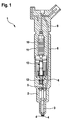
- schematisch einen Kraftstoffinjektor nach dem Stand der Technik;
- Fign 2a, 2b
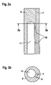
- einen Längsschnitt (
Fig. 2a ) und einen Querschnitt (Fig. 2b ) eines Haltekörpers des inFig. 1 gezeigten Kraftstoffinjektors nach dem Stand der Technik; - Fign. 3a, 3b
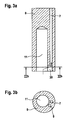
- einen Längsschnitt (
Fig. 3a ) und einen Querschnitt (Fig. 3b ) eines Haltekörpers des inFig. 1 gezeigten Kraftstoffinjektors nach dem Stand der Technik; - Fign. 4a, 4b
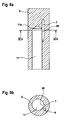
- einen Längsschnitt (
Fig. 4a ) und einen Querschnitt (Fig. 4b ) eines Haltekörpers eines erfindungsgemäßen Kraftstoffinjektors; - Fign. 5a, 5b
- einen Längsschnitt (
Fig. 5a ) und einen Querschnitt (Fig. 5b ) eines Haltekörpers eines nicht erfindungsgemäßen Kraftstoffinjektors; und - Fign. 6a, 6b
- einen Längsschnitt (
Fig. 6a ) und einen Querschnitt (Fig. 6b ) eines weiteren Haltekörpers eines nicht erfindungsgemäßen Kraftstoffinjektors. - Der in
Fig. 1 gezeigte bekannte Kraftstoffinjektor 1 wird üblicherweise bei einer Brennkraftmaschine mit mehreren Zylindern verwendet, wobei jedem dieser Zylinder ein solcher Injektor (Kraftstoffeinspritzventil) zugeordnet ist. Der Kraftstoffinjektor 1 umfasst: - eine in einem Düsenkörper 2 verschiebbar geführte Düsennadel 3, die eine oder mehrere Einspritzöffnungen 4 des Düsenkörpers 2 für eine Einspritzung mit unter Hochdruck stehendem Kraftstoff freigibt oder verschließt,
- einen an eine Hochdruckseite angeschlossenen Steuerraum 5, über dessen Druck die Bewegung der Düsennadel 3 gesteuert wird,
- ein Schaltventil 6, das die Verbindung des Steuerraums 5 zu einer niederdruckseitigen Rücklaufbohrung 7 (
Fig. 2 ) entweder sperrt oder öffnet, - einen den Düsenkörper 2 haltenden Haltekörper 8, in dem die Rücklaufbohrung 7 und eine sich bis zum Steuerraum 2 und zu den Einspritzöffnungen 4 erstreckende Hochdruckleitung 9 axial verlaufen, und
- ein piezoelektrisches Aktormodul 10 zum Betätigen des Schaltventils 6, wobei das piezoelektrische Aktormodul 10 in einer in Richtung auf den Düsenkörper 2 offenen und an die Rücklaufbohrung 7 angeschlossenen Aktorraumbohrung 11 des Haltekörpers 8 angeordnet ist.
- Die Rücklaufbohrung 7 und die Aktorraumbohrung 11 verlaufen im Haltekörper 8 parallel zueinander, wobei der Bohrungsdurchmesser der Aktorraumbohrung 11 wesentlich größer als der Bohrungsdurchmesser der Rücklaufbohrung 7 ist. Im gezeigten Ausführungsbeispiel ist die Aktorraumbohrung 11 als eine in Richtung fort vom Düsenkörper 2 geschlossene Sackbohrung ausgebildet.
- Das Schaltventil 6 weist als Ventilschließglied einen im Schaltventil 6 verschiebbar geführtes Ventilelement 12 auf, das mit dem piezoelektrischen Aktormodul 10 über einen hydraulischen Koppler 13 bewegungsgekoppelt ist. Das Ventilelement 12 sperrt in seiner geschlossenen Ventilstellung, d.h. bei stromlosem Aktormodul 10, die Verbindung des Steuerraums 5 zur Niederdruckseite, wodurch die Düsennadel 3 durch den im Steuerraum 5 herrschenden Hochdruck in ihrer die Einspritzöffnungen 4 verschließenden Stellung ist, und gibt in seiner geöffneten Ventilstellung, d.h. bei bestromtem Aktormodul 10, die Verbindung des Steuerraums 5 zur Niederdruckseite frei, wodurch sich der Druck im Steuerraum 5 reduziert und die Düsennadel 3 öffnet. Der beim Öffnen des Ventilelements 12 auftretende Druckstoß (Absteuerstoß) wird über die an die Rücklaufbohrung 7 angeschlossenen Aktorraumbohrung 11 abgeführt.
- Die
Fign. 2 und3 zeigen, wie beim Stand der Technik die Rücklaufbohrung 7 an die Aktorraumbohrung 11 angeschlossen ist. - Bei dem in
Fig. 2a und 2b gezeigten bekannten Haltekörper 8 strömt die Absteuermenge des Schaltventils 6 zunächst in die Aktorraumbohrung 11 und wird von dort über die als Tieflochbohrung bzw. Steigleitung ausgeführte Rücklaufbohrung 7 zum Rücklaufanschluss des Injektors weitergeleitet. Die Verbindung zwischen der Aktorraumbohrung 11 und der Rücklaufbohrung 7 ist durch zwei so genannte "Lecköl-Verbindungsbohrungen" 20 realisiert. Zur Fertigung dieser beiden Lecköl-Verbindungsbohrungen 20 muss ein Werkzeug in die Aktorraumbohrung 11 eingeführt werden, um die Lecköl-Verbindungsbohrungen 20 schräg bohren zu können, was aber einen erheblichen Fertigungsaufwand bedeutet. - Bei dem in
Fig. 3a und 3b gezeigten bekannten Haltekörper 8 ist die Verbindung zwischen Aktorraumbohrung 11 und Rücklaufbohrung 7 durch eine auf Höhe der Haltekörper-Dichtfläche angebrachte, gefräste Quernut 30, die so genannte "Flächenfreilegung", hergestellt. Bei unveränderter Funktion des Injektors wird der Fertigungsprozess für die Verbindung von Aktorraumbohrung 11 und Rücklaufbohrung 7 vereinfacht, allerdings stellt nun die gesamte Aktorraumbohrung 11 ein Totvolumen dar, welches deutlich langsamer durchspült wird als bei der inFig. 2 gezeigten Ausführung mit den Lecköl-Verbindungsbohrungen. Dies führt dazu, dass der Entlüftungsprozess der Aktorraumbohrung 11, der vor der Erstprüfung des Injektors erfolgen muss, - und dort insbesondere vor der Messung des Spannungsbedarfs - erheblich mehr Zeit in Anspruch nimmt, als bei der bekannten Ausführung nachFig. 2 der Fall war. Wird dieser Entlüftungsprozess nicht ausreichend lange durchgeführt, so ist bei der Nassprüfung die Aktorraumbohrung 11 noch vollständig mit Öl gefüllt. In Folge dessen bleibt dann der Druckstoß auf die Aktormodulmembran aus, der ansonsten durch jeden Öffnungsvorgang des Schaltventils 6 ausgelöst wird. Dadurch ist bei der Messung der Spannungsbedarf des Injektors niedriger als später im Fahrzeug, und es werden ein falscher Spannungsbedarf und etwas veränderte Einspritzmengen im IMA/ISA-Code abgelegt. Während der ersten Betriebsstunde im Fahrzeug würde dann der Spannungsbedarf dann schnell auf seinen eigentlichen Wert ansteigen, was zu Problemen im Feld führen konnte. Zur Lösung dieses Problems wurde das so genannte Vakuum-Entlüften eingeführt. Dabei wird der Injektor vor seiner Nassprüfung zunächst mit einem starken Unterdruck beaufschlagt, was zu einer Entfernung fast der gesamten im Injektor enthaltenen Luftmenge führt. Erst dann wird der Injektor mit Öl befüllt, wodurch eine luftfreie Befüllung der Aktorraumbohrung 11 schon zu Beginn der Nassprüfung sichergestellt ist. Dadurch wird der erhöhte Zeitaufwand für die Entlüftung der Aktorraumbohrung 11 vermieden; es entsteht aber ein erhöhter apparativer Aufwand für die Entlüftung. -
Fign. 4 bis 6 zeigen, wie erfindungsgemäß die Aktorraumbohrung 11 an die Rücklaufbohrung 7 angeschlossen ist. Im Vergleich zu denFign. 2 und3 ist in denFign. 4 bis 6 die Rücklaufbohrung 7 umso viel näher an die Aktorraumbohrung 11 verlegt, dass eine Überschneidung zwischen dem Querschnitt der Aktorraumbohrung 11 und dem Querschnitt der Rücklaufbohrung 7 entsteht. Voraussetzung ist, dass zuerst die Rücklaufbohrung 7 gefertigt wird und anschließend die wesentlich größere Aktorraumbohrung 11, die von der Rücklaufbohrung 7 dann nur am Rande tangiert wird. Außer dem Entgraten der Bohrungsverschneidungen sind keine zusätzlichen Arbeitsgänge als bisher erforderlich. Dafür entfallen das aufwändige Bohren der Lecköl-Verbindungsbohrungen 20 oder das Fräsen der Quernut 30. - Bei dem in
Fig. 4a und 4b gezeigten erfindungsgemäßen Haltekörper 8 erstreckt sich die Überschneidung 40 zwischen den parallel zueinander verlaufenden Rücklauf- und Aktorraumbohrungen 7, 11 auf der gesamten Länge der hier als Sackbohrung ausgeführten Aktorraumbohrung 11, d.h. von dem dem Düsenkörper 2 abgewandten geschlossenen Bohrungsende 11a bis zum offenen anderen Bohrungsende. Durch diese durchgängige Verbindung zwischen Aktorraumbohrung 11 und Rücklaufbohrung 7 ist eine sofortige und vollständige Entlüftung der Aktorraumbohrung 11 in den ersten Sekunden des Betriebs gewährleistet. Evtl. im Betrieb in die Aktorraumbohrung 11 eingespülte Luft kann ebenfalls sofort weiter in die Rücklaufbohrung 7 entweichen. - Vom Haltekörper der
Fign. 4a und 4b unterscheidet sich der inFig. 5a und 5b gezeigte nicht erfindungsgemäße Haltekörper 8 dadurch, dass hier die Rücklaufbohrung 7 nicht parallel, sondern schräg zur Aktorraumbohrung 11 gebohrt ist, wobei die Rücklauf- und Aktorraumbohrungen 7, 11 in einer gemeinsamen Ebene liegen, und dass die Überschneidung 50 zwischen der Aktorraumbohrung 11 und der Rücklaufbohrung 7 nur an dem dem Düsenkörper 2 abgewandten Bohrungsende oder -abschnitt 11a der Aktorraumbohrung 11 vorgesehen ist. - Vom Haltekörper der
Fign. 4a und 4b unterscheidet sich der inFig. 6a und 6b gezeigte nicht erfindungsgemäße Haltekörper 8 dadurch, dass hier die Rücklaufbohrung 7 nicht parallel, sondern schief zur Aktorraumbohrungen 11 gebohrt ist, wobei die Rücklauf- und Aktorraumbohrungen 7, 11 zueinander windschief verlaufen, also nicht in einer gemeinsamen Ebene liegen, und dass die Überschneidung 60 zwischen der Aktorraumbohrung 11 und der Rücklaufbohrung 7 nur an dem dem Düsenkörper 2 abgewandten Bohrungsende oder -abschnitt 11a der Aktorraumbohrung 11 vorgesehen ist.
Claims (5)
- Kraftstoffinjektor (1) für Brennkraftmaschinen, mit einer in einem Düsenkörper (2) verschiebbar geführten Düsennadel (3), die mindestens eine Einspritzöffnung (4) für eine Einspritzung mit unter Hochdruck stehendem Kraftstoff freigibt oder verschließt, mit einem an eine Hochdruckseite angeschlossenen Steuerraum (5), über dessen Druck die Bewegung der Düsennadel (3) gesteuert wird, mit einem Schaltventil (6), das die Verbindung des Steuerraums (5) zu einer niederdruckseitigen Rücklaufbohrung (7) entweder sperrt oder öffnet, mit einem den Düsenkörper (3) haltenden Haltekörper (8), in dem die Rücklaufbohrung (7) axial verläuft, und mit einem piezoelektrischen Aktormodul (10) zum Betätigen des Schaltventils (6), wobei das Aktormodul (10) in einer an die Rücklaufbohrung (7) angeschlossenen Aktorraumbohrung (11) des Haltekörpers (8) angeordnet ist,
dadurch gekennzeichnet, dass
der Haltekörper (8) auf der gesamten Länge der Aktorraumbohrung (11) eine Verschneidung (40) zwischen der Aktorraumbohrung (11) und der Rücklaufbohrung (7) aufweist. - Kraftstoffinjektor nach Anspruch 1, dadurch gekennzeichnet, dass die Aktorraumbohrung (11) und die Rücklaufbohrung (7) parallel zu einander verlaufen.
- Kraftstoffinjektor nach Anspruch 1 oder 2, dadurch gekennzeichnet, dass die Aktorraumbohrung (11) und die Rücklaufbohrung (7) in einer gemeinsamen Ebene liegen.
- Kraftstoffinjektor nach einem der vorhergehenden Ansprüche, dadurch gekennzeichnet, dass der Bohrungsdurchmesser der Aktorraumbohrung (11) größer als der Bohrungsdurchmesser der Rücklaufbohrung (7) ist.
- Kraftstoffinjektor nach einem der vorhergehenden Ansprüche, dadurch gekennzeichnet, dass das dem Düsenkörper (2) abgewandte Bohrungsende (11a) durch das geschlossene Ende der als Sackbohrung ausgebildeten Aktorraumbohrung (11) gebildet ist.
Applications Claiming Priority (1)
| Application Number | Priority Date | Filing Date | Title |
|---|---|---|---|
| DE102008040885A DE102008040885A1 (de) | 2008-07-31 | 2008-07-31 | Kraftstoffinjektor |
Publications (2)
| Publication Number | Publication Date |
|---|---|
| EP2149698A1 EP2149698A1 (de) | 2010-02-03 |
| EP2149698B1 true EP2149698B1 (de) | 2012-05-02 |
Family
ID=41396052
Family Applications (1)
| Application Number | Title | Priority Date | Filing Date |
|---|---|---|---|
| EP09100313A Not-in-force EP2149698B1 (de) | 2008-07-31 | 2009-06-02 | Kraftstoffinjektor |
Country Status (3)
| Country | Link |
|---|---|
| EP (1) | EP2149698B1 (de) |
| AT (1) | ATE556215T1 (de) |
| DE (1) | DE102008040885A1 (de) |
Family Cites Families (3)
| Publication number | Priority date | Publication date | Assignee | Title |
|---|---|---|---|---|
| JP4158338B2 (ja) * | 2000-06-06 | 2008-10-01 | 株式会社デンソー | インジェクタ用圧電体素子 |
| DE10250720A1 (de) | 2002-10-31 | 2004-05-13 | Robert Bosch Gmbh | Einspritzventil |
| DE102006019736A1 (de) * | 2006-04-28 | 2007-10-31 | Robert Bosch Gmbh | Kraftstoffinjektor |
-
2008
- 2008-07-31 DE DE102008040885A patent/DE102008040885A1/de not_active Withdrawn
-
2009
- 2009-06-02 EP EP09100313A patent/EP2149698B1/de not_active Not-in-force
- 2009-06-02 AT AT09100313T patent/ATE556215T1/de active
Also Published As
| Publication number | Publication date |
|---|---|
| ATE556215T1 (de) | 2012-05-15 |
| EP2149698A1 (de) | 2010-02-03 |
| DE102008040885A1 (de) | 2010-02-04 |
Similar Documents
| Publication | Publication Date | Title |
|---|---|---|
| WO2008138800A1 (de) | Injektor mit piezoaktor | |
| DE102008044096A1 (de) | Verfahren zur Herstellung von Drosselbohrungen mit niedrigem Kaviationsumschlagpunkt | |
| DE102006000035B4 (de) | Fluideinspritzventil | |
| EP1865192B1 (de) | Kraftstoffinjektor mit Servounterstützung | |
| DE102007042466B3 (de) | Einspritzsystem mit reduzierter Schaltleckage und Verfahren zum Herstellen eines Einspritzsystems | |
| EP1908952B1 (de) | Injektor für eine Kraftstoffeinspritzanlage | |
| EP1927748A2 (de) | Kraftstoffinjektor | |
| EP2149698B1 (de) | Kraftstoffinjektor | |
| DE102015226070A1 (de) | Kraftstoffinjektor | |
| EP2249024B1 (de) | Kraftstoffinjektor | |
| DE10139623A1 (de) | Einspritzanordnung für ein Kraftstoff-Speichereinspritzsystem | |
| EP1276983B1 (de) | Ventil zum steuern von flüssigkeiten | |
| DE102012210087A1 (de) | Pumpe, insbesondere Kraftstoffhochdruckpumpe für eine Kraftstoffeinspritzeinrichtung, und Kraftstoffeinspritzeinrichtung | |
| DE102010001612A1 (de) | Kraftstoffinjektor | |
| DE102005025141B3 (de) | Ventil | |
| DE102004035350B4 (de) | Kraftstoffeinspritzdüse für eine Brennkraftmaschine | |
| DE102007001365A1 (de) | Injektor mit Steuer- und Schaltkammer | |
| EP2439398A1 (de) | Brennstoffeinspritzventil | |
| DE102014220841A1 (de) | Einspritzventil zum Einspritzen von Fluid in einen Brennraum einer Brennkraftmaschine | |
| DE102005014180A1 (de) | Kraftstoffeinspritzeinrichtung für eine Brennkraftmaschine | |
| DE102014220779A1 (de) | Einspritzventil zum Einspritzen von Fluid in einen Brennraum einer Brennkraftmaschine | |
| DE102014211469A1 (de) | Düsenbaugruppe für einen Kraftstoffinjektor sowie Kraftstoffinjektor | |
| DE102006027484A1 (de) | Kraftstoffinjektor mit kraftausgeglichenem Steuerventil | |
| EP2199590A1 (de) | Kraftstoffinjektor | |
| DE10233574A1 (de) | Ventil zum Steuern von Flüssigkeiten |
Legal Events
| Date | Code | Title | Description |
|---|---|---|---|
| PUAI | Public reference made under article 153(3) epc to a published international application that has entered the european phase |
Free format text: ORIGINAL CODE: 0009012 |
|
| AK | Designated contracting states |
Kind code of ref document: A1 Designated state(s): AT BE BG CH CY CZ DE DK EE ES FI FR GB GR HR HU IE IS IT LI LT LU LV MC MK MT NL NO PL PT RO SE SI SK TR |
|
| 17P | Request for examination filed |
Effective date: 20100803 |
|
| 17Q | First examination report despatched |
Effective date: 20110117 |
|
| GRAP | Despatch of communication of intention to grant a patent |
Free format text: ORIGINAL CODE: EPIDOSNIGR1 |
|
| RIC1 | Information provided on ipc code assigned before grant |
Ipc: F02M 63/00 20060101ALI20111222BHEP Ipc: F02M 61/16 20060101ALI20111222BHEP Ipc: F02M 55/00 20060101ALI20111222BHEP Ipc: F02M 47/02 20060101AFI20111222BHEP |
|
| GRAS | Grant fee paid |
Free format text: ORIGINAL CODE: EPIDOSNIGR3 |
|
| GRAA | (expected) grant |
Free format text: ORIGINAL CODE: 0009210 |
|
| AK | Designated contracting states |
Kind code of ref document: B1 Designated state(s): AT BE BG CH CY CZ DE DK EE ES FI FR GB GR HR HU IE IS IT LI LT LU LV MC MK MT NL NO PL PT RO SE SI SK TR |
|
| REG | Reference to a national code |
Ref country code: GB Ref legal event code: FG4D Free format text: NOT ENGLISH |
|
| REG | Reference to a national code |
Ref country code: AT Ref legal event code: REF Ref document number: 556215 Country of ref document: AT Kind code of ref document: T Effective date: 20120515 Ref country code: CH Ref legal event code: EP |
|
| REG | Reference to a national code |
Ref country code: IE Ref legal event code: FG4D Free format text: LANGUAGE OF EP DOCUMENT: GERMAN |
|
| REG | Reference to a national code |
Ref country code: DE Ref legal event code: R096 Ref document number: 502009003438 Country of ref document: DE Effective date: 20120628 |
|
| REG | Reference to a national code |
Ref country code: NL Ref legal event code: VDEP Effective date: 20120502 |
|
| PGFP | Annual fee paid to national office [announced via postgrant information from national office to epo] |
Ref country code: FR Payment date: 20120705 Year of fee payment: 4 |
|
| REG | Reference to a national code |
Ref country code: LT Ref legal event code: MG4D Effective date: 20120530 |
|
| PG25 | Lapsed in a contracting state [announced via postgrant information from national office to epo] |
Ref country code: NO Free format text: LAPSE BECAUSE OF FAILURE TO SUBMIT A TRANSLATION OF THE DESCRIPTION OR TO PAY THE FEE WITHIN THE PRESCRIBED TIME-LIMIT Effective date: 20120802 Ref country code: PL Free format text: LAPSE BECAUSE OF FAILURE TO SUBMIT A TRANSLATION OF THE DESCRIPTION OR TO PAY THE FEE WITHIN THE PRESCRIBED TIME-LIMIT Effective date: 20120502 Ref country code: FI Free format text: LAPSE BECAUSE OF FAILURE TO SUBMIT A TRANSLATION OF THE DESCRIPTION OR TO PAY THE FEE WITHIN THE PRESCRIBED TIME-LIMIT Effective date: 20120502 Ref country code: CY Free format text: LAPSE BECAUSE OF FAILURE TO SUBMIT A TRANSLATION OF THE DESCRIPTION OR TO PAY THE FEE WITHIN THE PRESCRIBED TIME-LIMIT Effective date: 20120502 Ref country code: IS Free format text: LAPSE BECAUSE OF FAILURE TO SUBMIT A TRANSLATION OF THE DESCRIPTION OR TO PAY THE FEE WITHIN THE PRESCRIBED TIME-LIMIT Effective date: 20120902 Ref country code: LT Free format text: LAPSE BECAUSE OF FAILURE TO SUBMIT A TRANSLATION OF THE DESCRIPTION OR TO PAY THE FEE WITHIN THE PRESCRIBED TIME-LIMIT Effective date: 20120502 Ref country code: SE Free format text: LAPSE BECAUSE OF FAILURE TO SUBMIT A TRANSLATION OF THE DESCRIPTION OR TO PAY THE FEE WITHIN THE PRESCRIBED TIME-LIMIT Effective date: 20120502 |
|
| PG25 | Lapsed in a contracting state [announced via postgrant information from national office to epo] |
Ref country code: LV Free format text: LAPSE BECAUSE OF FAILURE TO SUBMIT A TRANSLATION OF THE DESCRIPTION OR TO PAY THE FEE WITHIN THE PRESCRIBED TIME-LIMIT Effective date: 20120502 Ref country code: GR Free format text: LAPSE BECAUSE OF FAILURE TO SUBMIT A TRANSLATION OF THE DESCRIPTION OR TO PAY THE FEE WITHIN THE PRESCRIBED TIME-LIMIT Effective date: 20120803 Ref country code: HR Free format text: LAPSE BECAUSE OF FAILURE TO SUBMIT A TRANSLATION OF THE DESCRIPTION OR TO PAY THE FEE WITHIN THE PRESCRIBED TIME-LIMIT Effective date: 20120502 Ref country code: PT Free format text: LAPSE BECAUSE OF FAILURE TO SUBMIT A TRANSLATION OF THE DESCRIPTION OR TO PAY THE FEE WITHIN THE PRESCRIBED TIME-LIMIT Effective date: 20120903 Ref country code: SI Free format text: LAPSE BECAUSE OF FAILURE TO SUBMIT A TRANSLATION OF THE DESCRIPTION OR TO PAY THE FEE WITHIN THE PRESCRIBED TIME-LIMIT Effective date: 20120502 |
|
| BERE | Be: lapsed |
Owner name: ROBERT BOSCH G.M.B.H. Effective date: 20120630 |
|
| PG25 | Lapsed in a contracting state [announced via postgrant information from national office to epo] |
Ref country code: CZ Free format text: LAPSE BECAUSE OF FAILURE TO SUBMIT A TRANSLATION OF THE DESCRIPTION OR TO PAY THE FEE WITHIN THE PRESCRIBED TIME-LIMIT Effective date: 20120502 Ref country code: DK Free format text: LAPSE BECAUSE OF FAILURE TO SUBMIT A TRANSLATION OF THE DESCRIPTION OR TO PAY THE FEE WITHIN THE PRESCRIBED TIME-LIMIT Effective date: 20120502 Ref country code: SK Free format text: LAPSE BECAUSE OF FAILURE TO SUBMIT A TRANSLATION OF THE DESCRIPTION OR TO PAY THE FEE WITHIN THE PRESCRIBED TIME-LIMIT Effective date: 20120502 Ref country code: EE Free format text: LAPSE BECAUSE OF FAILURE TO SUBMIT A TRANSLATION OF THE DESCRIPTION OR TO PAY THE FEE WITHIN THE PRESCRIBED TIME-LIMIT Effective date: 20120502 Ref country code: RO Free format text: LAPSE BECAUSE OF FAILURE TO SUBMIT A TRANSLATION OF THE DESCRIPTION OR TO PAY THE FEE WITHIN THE PRESCRIBED TIME-LIMIT Effective date: 20120502 Ref country code: NL Free format text: LAPSE BECAUSE OF FAILURE TO SUBMIT A TRANSLATION OF THE DESCRIPTION OR TO PAY THE FEE WITHIN THE PRESCRIBED TIME-LIMIT Effective date: 20120502 Ref country code: MC Free format text: LAPSE BECAUSE OF NON-PAYMENT OF DUE FEES Effective date: 20120630 |
|
| PG25 | Lapsed in a contracting state [announced via postgrant information from national office to epo] |
Ref country code: MK Free format text: LAPSE BECAUSE OF FAILURE TO SUBMIT A TRANSLATION OF THE DESCRIPTION OR TO PAY THE FEE WITHIN THE PRESCRIBED TIME-LIMIT Effective date: 20120502 |
|
| PGFP | Annual fee paid to national office [announced via postgrant information from national office to epo] |
Ref country code: IT Payment date: 20120630 Year of fee payment: 4 |
|
| PLBE | No opposition filed within time limit |
Free format text: ORIGINAL CODE: 0009261 |
|
| STAA | Information on the status of an ep patent application or granted ep patent |
Free format text: STATUS: NO OPPOSITION FILED WITHIN TIME LIMIT |
|
| REG | Reference to a national code |
Ref country code: IE Ref legal event code: MM4A |
|
| 26N | No opposition filed |
Effective date: 20130205 |
|
| PG25 | Lapsed in a contracting state [announced via postgrant information from national office to epo] |
Ref country code: IE Free format text: LAPSE BECAUSE OF NON-PAYMENT OF DUE FEES Effective date: 20120602 Ref country code: ES Free format text: LAPSE BECAUSE OF FAILURE TO SUBMIT A TRANSLATION OF THE DESCRIPTION OR TO PAY THE FEE WITHIN THE PRESCRIBED TIME-LIMIT Effective date: 20120813 Ref country code: BE Free format text: LAPSE BECAUSE OF NON-PAYMENT OF DUE FEES Effective date: 20120630 |
|
| REG | Reference to a national code |
Ref country code: DE Ref legal event code: R097 Ref document number: 502009003438 Country of ref document: DE Effective date: 20130205 |
|
| PG25 | Lapsed in a contracting state [announced via postgrant information from national office to epo] |
Ref country code: MT Free format text: LAPSE BECAUSE OF FAILURE TO SUBMIT A TRANSLATION OF THE DESCRIPTION OR TO PAY THE FEE WITHIN THE PRESCRIBED TIME-LIMIT Effective date: 20120502 Ref country code: BG Free format text: LAPSE BECAUSE OF FAILURE TO SUBMIT A TRANSLATION OF THE DESCRIPTION OR TO PAY THE FEE WITHIN THE PRESCRIBED TIME-LIMIT Effective date: 20120802 |
|
| REG | Reference to a national code |
Ref country code: CH Ref legal event code: PL |
|
| GBPC | Gb: european patent ceased through non-payment of renewal fee |
Effective date: 20130602 |
|
| REG | Reference to a national code |
Ref country code: FR Ref legal event code: ST Effective date: 20140228 |
|
| PG25 | Lapsed in a contracting state [announced via postgrant information from national office to epo] |
Ref country code: GB Free format text: LAPSE BECAUSE OF NON-PAYMENT OF DUE FEES Effective date: 20130602 Ref country code: CH Free format text: LAPSE BECAUSE OF NON-PAYMENT OF DUE FEES Effective date: 20130630 Ref country code: LI Free format text: LAPSE BECAUSE OF NON-PAYMENT OF DUE FEES Effective date: 20130630 Ref country code: TR Free format text: LAPSE BECAUSE OF FAILURE TO SUBMIT A TRANSLATION OF THE DESCRIPTION OR TO PAY THE FEE WITHIN THE PRESCRIBED TIME-LIMIT Effective date: 20120502 |
|
| PG25 | Lapsed in a contracting state [announced via postgrant information from national office to epo] |
Ref country code: FR Free format text: LAPSE BECAUSE OF NON-PAYMENT OF DUE FEES Effective date: 20130701 Ref country code: LU Free format text: LAPSE BECAUSE OF NON-PAYMENT OF DUE FEES Effective date: 20120602 Ref country code: IT Free format text: LAPSE BECAUSE OF NON-PAYMENT OF DUE FEES Effective date: 20130602 |
|
| PG25 | Lapsed in a contracting state [announced via postgrant information from national office to epo] |
Ref country code: HU Free format text: LAPSE BECAUSE OF FAILURE TO SUBMIT A TRANSLATION OF THE DESCRIPTION OR TO PAY THE FEE WITHIN THE PRESCRIBED TIME-LIMIT Effective date: 20090602 |
|
| REG | Reference to a national code |
Ref country code: AT Ref legal event code: MM01 Ref document number: 556215 Country of ref document: AT Kind code of ref document: T Effective date: 20140602 |
|
| PG25 | Lapsed in a contracting state [announced via postgrant information from national office to epo] |
Ref country code: AT Free format text: LAPSE BECAUSE OF NON-PAYMENT OF DUE FEES Effective date: 20140602 |
|
| PGFP | Annual fee paid to national office [announced via postgrant information from national office to epo] |
Ref country code: DE Payment date: 20190822 Year of fee payment: 11 |
|
| REG | Reference to a national code |
Ref country code: DE Ref legal event code: R119 Ref document number: 502009003438 Country of ref document: DE |
|
| PG25 | Lapsed in a contracting state [announced via postgrant information from national office to epo] |
Ref country code: DE Free format text: LAPSE BECAUSE OF NON-PAYMENT OF DUE FEES Effective date: 20210101 |