EP2149660A2 - Drive case for a fitting on a connecting rod - Google Patents
Drive case for a fitting on a connecting rod Download PDFInfo
- Publication number
- EP2149660A2 EP2149660A2 EP09164636A EP09164636A EP2149660A2 EP 2149660 A2 EP2149660 A2 EP 2149660A2 EP 09164636 A EP09164636 A EP 09164636A EP 09164636 A EP09164636 A EP 09164636A EP 2149660 A2 EP2149660 A2 EP 2149660A2
- Authority
- EP
- European Patent Office
- Prior art keywords
- threaded sleeves
- drive
- housing
- housing parts
- drive housing
- Prior art date
- Legal status (The legal status is an assumption and is not a legal conclusion. Google has not performed a legal analysis and makes no representation as to the accuracy of the status listed.)
- Granted
Links
- 230000000295 complement effect Effects 0.000 claims description 2
- 238000003780 insertion Methods 0.000 abstract description 4
- 230000037431 insertion Effects 0.000 abstract description 4
- 238000004519 manufacturing process Methods 0.000 description 2
- 239000000463 material Substances 0.000 description 2
- 238000004512 die casting Methods 0.000 description 1
- 239000002184 metal Substances 0.000 description 1
Images

Classifications
-
- E—FIXED CONSTRUCTIONS
- E05—LOCKS; KEYS; WINDOW OR DOOR FITTINGS; SAFES
- E05C—BOLTS OR FASTENING DEVICES FOR WINGS, SPECIALLY FOR DOORS OR WINDOWS
- E05C9/00—Arrangements of simultaneously actuated bolts or other securing devices at well-separated positions on the same wing
- E05C9/02—Arrangements of simultaneously actuated bolts or other securing devices at well-separated positions on the same wing with one sliding bar for fastening when moved in one direction and unfastening when moved in opposite direction; with two sliding bars moved in the same direction when fastening or unfastening
- E05C9/021—Arrangements of simultaneously actuated bolts or other securing devices at well-separated positions on the same wing with one sliding bar for fastening when moved in one direction and unfastening when moved in opposite direction; with two sliding bars moved in the same direction when fastening or unfastening with rack and pinion mechanism
Definitions
- the invention relates to a drive housing for a drive rod fitting a window, a door or the like, in the at least one drive pinion for driving a parallel to the window plane longitudinally movable drive rod and one or more axially over a range of movement longitudinally guided threaded sleeves for screwing with a handle for actuating the drive rod fitting are included.
- a drive housing of the above type is for example from the EP 0 674 02071 B1 known.
- the drive housing is inserted into a pocket of the profile of a window or door. After insertion can be performed by the parallel to the axis of rotation of the drive pinion holes for the Griffverschraubungen a tool that releases the threaded sleeves from an engagement position and pushes by spring force in the direction of the holes for the grips against a wall of the bag.
- the displaceability of the threaded sleeves is limited by a stop in the drive housing.
- the drive housing is then bolted to a handle assembly by means of two parallel to the axis of rotation of the drive pinion screws.
- the handle assembly has a base plate for bolting to the drive housing and a handle for connection to the drive pinion. While the drive housing is inserted inside the pocket of the profile, the base plate rests on the outside of the profile.
- a disadvantage of the known drive housing is that the handle can only be screwed from one side into the threaded sleeves and therefore the threaded side of the threaded sleeve must be mounted in the correct position on the side of the holes for the grip fittings.
- Another disadvantage is that a tool is required for the disengagement of the threaded sleeves, which must be cumbersome performed by the holes for the handle fitting to each threaded sleeve to release the threaded sleeves from the engaged position.
- the invention is based on the problems to form a drive housing of the type mentioned so that the threaded sleeves can be used in both directions of the screw axis and that for the release of the threaded sleeves from the engagement position no tool is required.
- the engagement position is located in the middle of the range of movement of the threaded sleeves, so that the threaded sleeves in the engagement position do not protrude the side surfaces of the receptacle for the drive pinion and the range of movement of the threaded sleeves after release from the engagement position in both directions unhindered by the recording for the drive pinion.
- the threaded sleeves are solved when screwing with the handle assembly by overcoming a predetermined load from the engagement position.
- the threaded sleeves are freely movable at least above a predetermined load in both directions of the screw axis.
- the threaded sleeves can transmit little or no tilting forces on the recording for the drive pinion.
- a strong tightening the screws for the handle assembly causes the threaded sleeves move to the limit of the pocket in the profile of the window or door for the drive housing according to the invention.
- the handle is thus reliably held on the window or door.
- the threaded sleeves could be separately mounted on the drive housing components or components connected to the drive housing, if this connection is released above the intended load.
- the drive housing may optionally be provided for a so-called edge gear of a window fitting or for a mortise lock of a building door.
- the mounting of the drive housing in the window or the door is particularly simple when the threaded sleeves are elastically connected to the drive housing.
- the elastic support of the threaded sleeve on the drive housing after mounting the drive pinion according to the invention on the window or the door also avoids disturbing noises in the operation of the espagnolette fitting.
- the drive housing according to the invention is thus easily disassembled together with the screw sleeves.
- the elastic connection of the threaded sleeves with the drive housing and the entire drive pinion is particularly suitable plastic.
- the proposed load, above which the threaded sleeves are guided longitudinally displaceable in the drive housing is determined here by the elasticity of the connection of the threaded sleeve with the drive housing.
- the drive housing according to the invention can be manufactured particularly cost-effectively from any inelastic material, if a predetermined breaking point is arranged between the threaded sleeves and the drive housing.
- a material for the production of the predetermined breaking point having drive housing is suitable for example metal die casting.
- the proposed load, above which the threaded sleeves are guided longitudinally displaceable in the drive housing, is determined here by the stability of the predetermined breaking point.
- connection of the drive housing with the threaded sleeves designed in accordance with another advantageous embodiment of the invention structurally particularly simple when the connection of the threaded sleeves with the drive housing has a web.
- the web can in this case be designed elastically deformable or designed as a predetermined breaking point.
- the assembly of the drive housing according to the invention is particularly simple if it has two opposing housing parts and when the housing parts are connected to each other via a latching connection.
- a tilting of the threaded sleeve relative to the drive housing can be according to another advantageous embodiment of the invention easily avoided if the threaded sleeves has a guide web, the drive housing a complementary to the guide web designed guide.
- the guide bar is vozugweise T-shaped or L-shaped.
- the guide web located in the guide prevents rotation of the Threaded sleeve when screwed to the handle assembly and also ensures that the drive housing according to the invention after screwing with the handle assembly can not fall out of the pocket in the profile.
- the guides of the threaded sleeves on the drive housing can be designed particularly elongated according to another advantageous embodiment of the invention, when the threaded sleeves are arranged on one of the housing parts and guide grooves for the threaded sleeves on the other of the housing parts. This design leads to a high stability of the drive housing according to the invention.
- the two housing parts are designed identically and each have one of the threaded sleeves and a guide groove for the threaded sleeve of the opposite housing part.
- the drive housing according to the invention is particularly compact and can be manufactured inexpensively if the housing parts each have a portion of a guide for the drive rod.
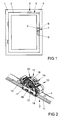
- FIG. 1 shows a window with a pivotable against a frame 1 wings 2 and with a drive rod fitting 3 for locking the wing 2 in the frame 1.
- the espagnolette fitting 3 has a longitudinally displaceable guided in the wing 2 drive rod 4 for driving a shutter 5 of the espagnolette fitting 3.
- the drive rod 4 can be controlled by a handle 6 a handle assembly 7.
- the handle 6 is rotatably mounted on a base plate 8 of the handle assembly 7.
- the base plate 8 is screwed by means of screws 9, one of which is covered by the handle 6, to the window.
- FIG. 2 shows in perspective one of the handle 6 from FIG. 1 actuatable drive device 10 of the drive rod fitting 3 from FIG. 1 with the drive rod 4 and a drive rod 4 covering the faceplate 11.
- the drive device 10 has a drive housing 12 with a drive pinion mounted therein 13 for the drive rod 4.
- On the drive housing 12 are threaded sleeves 23, 24 with threaded holes 14, 15 for receiving the in FIG. 1 described screws 9 attached.
- the drive pinion 13 has a square socket 16, with the it rotatably in the assembled state with the in FIG. 1 shown handle 6 is coupled.
- the drive housing 12 has two housing parts 17, 18 for the illustrated drive pinion 13.
- the housing parts 17, 18 are connected via snap-in connections 19, 20 with each other.
- FIG. 3 shows a greatly enlarged perspective view of the drive housing 12 of the drive device 10 from FIG. 2 in an exploded view.
- the housing parts 17, 18 define a receptacle 21 for in FIG. 2
- One of the housing parts 18 has two arranged on the receptacle 21 for the drive pinion 13 threaded sleeves 23, 24 with the threaded holes 14, 15.
- the threaded sleeves 23, 24 are used for screwing in in FIG. 1 shown screws 9 for holding the handle assembly 7.
- the housing parts 18 and the threaded sleeves 23, 24 are connected via a web 25 with each other.
- the threaded sleeves 23, 24 have L-shaped guide webs 26, 27.
- the other of the housing parts 17 has guide grooves 28, 29 for receiving the guide webs 26, 27 of the threaded sleeves 23, 24.
- the guide grooves 28, 29 having housing part 17 also has latching hooks 30 for engaging behind locking lugs 31 of the other housing part 18.
- FIG. 4 shows greatly enlarged in a perspective view of another embodiment of the drive housing 12 from FIG. 2 with two housing parts 32, 33.
- the housing parts 32, 33 define the drive housing 12 FIG. 2 and a guide 35 for the drive rod 4.
- Each of the housing parts 32, 33 has a threaded sleeve 36, 37 with the threaded holes for the screws FIG. 1 on.
- the threaded sleeves 36, 37 are respectively via webs 38, 39 with the receiving 34 bounding areas of the housing parts 32, 33 connected.
- each guide webs 40, 41 for insertion in guide grooves 42, 43 of the other housing part 32, 33 are arranged.
- housing parts 32, 33 each have a latching hook 44, 45 and a latching nose 46, 47, and a centering nose 48 and a centering recess 49 and can be like FIG. 3 put together.
- the housing parts 32, 33 are constructed identically.
- the webs 25, 38, 39 in the two in FIGS. 3 and 4 illustrated embodiments of the drive housing 12 are either designed as predetermined breaking points and break above a proposed load or they are designed elastic. This allows the threaded sleeves 23, 24, 36, 37 when tightening the screws 9 for the handle assembly 7 with the guide webs 26, 27, 40, 41 along the guide grooves 28, 29, 42, 43 can move. The introduction of tilting forces in the drive housing 12 is thereby prevented.
Landscapes
- Engineering & Computer Science (AREA)
- Mechanical Engineering (AREA)
- Lock And Its Accessories (AREA)
- Power-Operated Mechanisms For Wings (AREA)
- Shafts, Cranks, Connecting Bars, And Related Bearings (AREA)
- Patch Boards (AREA)
Abstract
Description
Die Erfindung betrifft ein Antriebsgehäuse für einen Treibstangenbeschlag eines Fensters, einer Tür oder dergleichen, in dem mindestens ein Antriebsritzel zum Antrieb einer parallel zur Fensterebene längsverschieblichen Treibstange und einer oder mehrerer in Achsrichtung über einen Bewegungsbereich längsverschieblich geführten Gewindehülsen zur Verschraubung mit einem Griff zur Betätigung des Treibstangenbeschlages aufgenommen sind.The invention relates to a drive housing for a drive rod fitting a window, a door or the like, in the at least one drive pinion for driving a parallel to the window plane longitudinally movable drive rod and one or more axially over a range of movement longitudinally guided threaded sleeves for screwing with a handle for actuating the drive rod fitting are included.
Ein Antriebsgehäuse der vorstehenden Art ist beispielsweise aus der
Nachteilig bei dem bekannten Antriebsgehäuse ist jedoch, dass der Griff nur von einer Seite in den Gewindehülsen verschraubt werden kann und daher die Verschraubungsseite der Gewindehülse lagerichtig auf der Seite der Bohrungen für die Griffverschraubungen montiert werden muss.A disadvantage of the known drive housing, however, is that the handle can only be screwed from one side into the threaded sleeves and therefore the threaded side of the threaded sleeve must be mounted in the correct position on the side of the holes for the grip fittings.
Weiterhin nachteilig ist, dass für das Ausrücken der Gewindehülsen ein Werkzeug erforderlich ist, welches umständlich durch die Bohrungen für die Griffverschraubung zu jeder Gewindehülse geführt werden muss, um die Gewindehülsen aus der Einrückposition zu lösen.Another disadvantage is that a tool is required for the disengagement of the threaded sleeves, which must be cumbersome performed by the holes for the handle fitting to each threaded sleeve to release the threaded sleeves from the engaged position.
Der Erfindung liegen die Probleme zugrunde, ein Antriebsgehäuse der eingangs genannten Art so weiter zu bilden, dass die Gewindehülsen in beiden Richtungen der Schraubachse verwendet werden können und das für das Lösen der Gewindehülsen aus der Einrückposition kein Werkzeug erforderlich ist.The invention is based on the problems to form a drive housing of the type mentioned so that the threaded sleeves can be used in both directions of the screw axis and that for the release of the threaded sleeves from the engagement position no tool is required.
Diese Probleme werden erfindungsgemäß dadurch gelöst, dass sich die Einrückstellung in der Mitte des Bewegungsbereich der Gewindehülsen befindet, so dass die Gewindehülsen in der Einrückstellung die Seitenflächen der Aufnahme für das Antriebsritzel nicht überragen und der Bewegungsbereich der Gewindehülsen nach dem Lösen aus der Einrückstellung in beiden Richtungen ungehindert von der Aufnahme für das Antriebsritzel ist. Die Gewindehülsen werden beim Verschrauben mit der Griffbaugruppe durch das Überwinden einer vorgesehenen Belastung aus der Einrückstellung gelöst.These problems are inventively achieved in that the engagement position is located in the middle of the range of movement of the threaded sleeves, so that the threaded sleeves in the engagement position do not protrude the side surfaces of the receptacle for the drive pinion and the range of movement of the threaded sleeves after release from the engagement position in both directions unhindered by the recording for the drive pinion. The threaded sleeves are solved when screwing with the handle assembly by overcoming a predetermined load from the engagement position.
Durch diese Gestaltung sind die Gewindehülsen zumindest oberhalb einer vorgesehenen Belastung in beiden Richtungen der Schraubachse frei beweglich. Damit können die Gewindehülsen keine oder nur geringe Kippkräfte auf die Aufnahme für das Antriebsritzel übertragen. Ein kräftiges Anziehen der Schrauben für die Griffbaugruppe führt dazu, dass sich die Gewindehülsen bis zur Begrenzung der Tasche im Profil des Fensters oder der Tür für das erfindungsgemäße Antriebsgehäuse bewegen. Der Griff wird damit zuverlässig an dem Fenster oder der Tür gehalten. Die Gewindehülsen könnten dabei separat an dem Antriebsgehäuse montierte Bauteile sein oder mit dem Antriebsgehäuse verbundene Bauteile sein, wenn diese Verbindung oberhalb der vorgesehenen Belastung gelöst wird. Das Antriebsgehäuse kann wahlweise für ein so genanntes Kantengetriebe eines Fensterbeschlages oder auch für ein Einsteckschloss einer Gebäudetür vorgesehen sein.By this design, the threaded sleeves are freely movable at least above a predetermined load in both directions of the screw axis. Thus, the threaded sleeves can transmit little or no tilting forces on the recording for the drive pinion. A strong tightening the screws for the handle assembly causes the threaded sleeves move to the limit of the pocket in the profile of the window or door for the drive housing according to the invention. The handle is thus reliably held on the window or door. The threaded sleeves could be separately mounted on the drive housing components or components connected to the drive housing, if this connection is released above the intended load. The drive housing may optionally be provided for a so-called edge gear of a window fitting or for a mortise lock of a building door.
Die Montage des Antriebsgehäuses in dem Fenster oder der Tür gestaltet sich besonders einfach, wenn die Gewindehülsen elastisch mit dem Antriebsgehäuse verbunden sind. Die elastische Halterung der Gewindehülse an dem Antriebsgehäuse nach der Montage des erfindungsgemäßen Antriebsritzels an dem Fenster oder der Tür vermeidet zudem störende Geräusche bei der Betätigung des Treibstangenbeschlages. Zudem ist das erfindungsgemäße Antriebsgehäuse hierdurch zusammen mit den Schraubhülsen einfach demontierbar. Für die elastische Verbindung der Gewindehülsen mit dem Antriebsgehäuse und des gesamten Antriebsritzels eignet sich insbesondere Kunststoff. Die vorgesehene Belastung, oberhalb der die Gewindehülsen längsverschieblich in dem Antriebsgehäuse geführt sind, wird hier durch die Elastizität der Verbindung der Gewindehülse mit dem Antriebsgehäuse bestimmt.The mounting of the drive housing in the window or the door is particularly simple when the threaded sleeves are elastically connected to the drive housing. The elastic support of the threaded sleeve on the drive housing after mounting the drive pinion according to the invention on the window or the door also avoids disturbing noises in the operation of the espagnolette fitting. In addition, the drive housing according to the invention is thus easily disassembled together with the screw sleeves. For the elastic connection of the threaded sleeves with the drive housing and the entire drive pinion is particularly suitable plastic. The proposed load, above which the threaded sleeves are guided longitudinally displaceable in the drive housing, is determined here by the elasticity of the connection of the threaded sleeve with the drive housing.
Das erfindungsgemäße Antriebsgehäuse lässt sich besonders kostengünstig aus einem beliebigen unelastischen Material fertigen, wenn zwischen den Gewindehülsen und dem Antriebsgehäuse eine Sollbruchstelle angeordnet ist. Als Material zur Fertigung des die Sollbruchstelle aufweisenden Antriebsgehäuses eignet sich beispielsweise Metalldruckguss. Die vorgesehene Belastung, oberhalb der die Gewindehülsen längsverschieblich in dem Antriebsgehäuse geführt sind, wird hier durch die Stabilität der Sollbruchstelle bestimmt.The drive housing according to the invention can be manufactured particularly cost-effectively from any inelastic material, if a predetermined breaking point is arranged between the threaded sleeves and the drive housing. As a material for the production of the predetermined breaking point having drive housing is suitable for example metal die casting. The proposed load, above which the threaded sleeves are guided longitudinally displaceable in the drive housing, is determined here by the stability of the predetermined breaking point.
Die Verbindung des Antriebsgehäuses mit den Gewindehülsen gestaltet sich gemäß einer anderen vorteilhaften Weiterbildung der Erfindung konstruktiv besonders einfach, wenn die Verbindung der Gewindehülsen mit dem Antriebsgehäuse einen Steg aufweist. Der Steg kann hierbei elastisch verformbar gestaltet oder als Sollbruchstelle ausgebildet sein.The connection of the drive housing with the threaded sleeves designed in accordance with another advantageous embodiment of the invention structurally particularly simple when the connection of the threaded sleeves with the drive housing has a web. The web can in this case be designed elastically deformable or designed as a predetermined breaking point.
Die Montage des erfindungsgemäßen Antriebsgehäuses gestaltet sich besonders einfach, wenn es zwei einander gegenüberstehende Gehäuseteile hat und wenn die Gehäuseteile über eine Rastverbindung miteinander verbunden sind.The assembly of the drive housing according to the invention is particularly simple if it has two opposing housing parts and when the housing parts are connected to each other via a latching connection.
Ein Kippen der Gewindehülse gegenüber dem Antriebsgehäuse lässt sich gemäß einer anderen vorteilhaften Weiterbildung der Erfindung einfach vermeiden, wenn die Gewindehülsen einen Führungssteg das Antriebsgehäuse eine komplementär zu dem Führungssteg gestaltete Führungsnut aufweist. Hierdurch wird sichergestellt, dass das Antriebsgehäuse auch nach einer Relativbewegung der Gewindehülsen zuverlässig in seiner Lage im Fenster oder in der Tür gehalten ist. Der Führungssteg ist vozugweise T-förmig oder L-förmig gestaltet. Der in der Führungsnut befindliche Führungssteg verhindert ein Verdrehen der Gewindehülse bei der Verschraubung mit der Griffbaugruppe und stellt zudem sicher, dass das erfindungsgemäße Antriebsgehäuse nach der Verschraubung mit der Griffbaugruppe nicht aus der Tasche im Profil herausfallen kann.A tilting of the threaded sleeve relative to the drive housing can be according to another advantageous embodiment of the invention easily avoided if the threaded sleeves has a guide web, the drive housing a complementary to the guide web designed guide. This ensures that the drive housing is reliably held in its position in the window or in the door even after a relative movement of the threaded sleeves. The guide bar is vozugweise T-shaped or L-shaped. The guide web located in the guide prevents rotation of the Threaded sleeve when screwed to the handle assembly and also ensures that the drive housing according to the invention after screwing with the handle assembly can not fall out of the pocket in the profile.
Die Führungen der Gewindehülsen an dem Antriebsgehäuse können gemäß einer anderen vorteilhaften Weiterbildung der Erfindung besonders langgestreckt gestaltet sein, wenn die Gewindehülsen an einem der Gehäuseteile und Führungsnuten für die Gewindehülsen an dem anderen der Gehäuseteile angeordnet sind. Diese Gestaltung führt zu einer hohen Stabilität des erfindungsgemäßen Antriebsgehäuses.The guides of the threaded sleeves on the drive housing can be designed particularly elongated according to another advantageous embodiment of the invention, when the threaded sleeves are arranged on one of the housing parts and guide grooves for the threaded sleeves on the other of the housing parts. This design leads to a high stability of the drive housing according to the invention.
Zur Verringerung der Fertigunskosten bei einer Serienfertigung des erfindungsgemäßen Antriebsgehäuses trägt es bei, wenn die beiden Gehäuseteile identisch gestaltet sind und jeweils eine der Gewindehülsen und eine Führungsnut für die Gewindehülse des gegenüberstehenden Gehäuseteils aufweisen.To reduce the Fertigunkosten in a mass production of the drive housing according to the invention, it helps if the two housing parts are designed identically and each have one of the threaded sleeves and a guide groove for the threaded sleeve of the opposite housing part.
Eine vorgesehene Ausrichtung der Gehäuseteile zueinander gestaltet sich gemäß einer anderen vorteilhaften Weiterbildung der Erfindung konstruktiv besonders einfach, wenn die Gehäuseteile einander entsprechende Zentriernasen und Zentrierausnehmungen aufweisen.An intended alignment of the housing parts to each other according to another advantageous embodiment of the invention structurally particularly simple when the housing parts have mutually corresponding centering and Zentrierausnehmungen.
Das erfindungsgemäße Antriebsgehäuse gestaltet sich besonders kompakt und lässt sich kostengünstig fertigen, wenn die Gehäuseteile jeweils einen Teilbereich einer Führung für die Treibstange haben.The drive housing according to the invention is particularly compact and can be manufactured inexpensively if the housing parts each have a portion of a guide for the drive rod.
Die Erfindung lässt zahlreiche Ausführungsformen zu. Zur weiteren Verdeutlichung ihres Grundprinzips sind zwei davon in der Zeichnung dargestellt und werden nachfolgend beschrieben. Diese zeigt in
- Fig. 1
- ein Fenster mit einem Treibstangenbeschlag,
- Fig. 2
- vergrößert in einer perspektivischen Darstellung ein Antriebsgehäuse mit einer Treibstange des Treibstangenbeschlages aus
Figur 1 - Fig. 3
- stark vergrößert eine Explosionsdarstellung des Antriebsgehäuses des Treibstangenbeschlages aus
Figur 1 - Fig. 4
- eine weitere Ausführungsform des Antriebsgehäuses in einer Explosionsdarstellung.
- Fig. 1
- a window with a driving rod fitting,
- Fig. 2
- enlarged in a perspective view of a drive housing with a drive rod of the espagnolette
FIG. 1 . - Fig. 3
- greatly increases an exploded view of the drive housing of the espagnolette
FIG. 1 . - Fig. 4
- a further embodiment of the drive housing in an exploded view.
Die Stege 25, 38, 39 in den beiden in
Claims (10)
Priority Applications (2)
| Application Number | Priority Date | Filing Date | Title |
|---|---|---|---|
| PL09164636T PL2149660T3 (en) | 2008-07-29 | 2009-07-06 | Drive case for a fitting on a connecting rod |
| SI200930523T SI2149660T1 (en) | 2008-07-29 | 2009-07-06 | Drive case for a fitting on a connecting rod |
Applications Claiming Priority (1)
| Application Number | Priority Date | Filing Date | Title |
|---|---|---|---|
| DE102008040842A DE102008040842A1 (en) | 2008-07-29 | 2008-07-29 | Drive housing for a drive rod fitting |
Publications (3)
| Publication Number | Publication Date |
|---|---|
| EP2149660A2 true EP2149660A2 (en) | 2010-02-03 |
| EP2149660A3 EP2149660A3 (en) | 2011-07-27 |
| EP2149660B1 EP2149660B1 (en) | 2012-11-28 |
Family
ID=41050351
Family Applications (1)
| Application Number | Title | Priority Date | Filing Date |
|---|---|---|---|
| EP09164636A Active EP2149660B1 (en) | 2008-07-29 | 2009-07-06 | Drive case for a fitting on a connecting rod |
Country Status (5)
| Country | Link |
|---|---|
| EP (1) | EP2149660B1 (en) |
| DE (1) | DE102008040842A1 (en) |
| ES (1) | ES2397308T3 (en) |
| PL (1) | PL2149660T3 (en) |
| SI (1) | SI2149660T1 (en) |
Cited By (2)
| Publication number | Priority date | Publication date | Assignee | Title |
|---|---|---|---|---|
| EP2532816A1 (en) | 2011-06-08 | 2012-12-12 | Roto Frank Ag | Actuation device for a fitting on a connecting rod |
| EP2735677A1 (en) * | 2012-11-21 | 2014-05-28 | Vita Corporation Co., Ltd. | Operating system for doors/windows with multiple locking points |
Citations (1)
| Publication number | Priority date | Publication date | Assignee | Title |
|---|---|---|---|---|
| EP0674071B1 (en) | 1994-03-23 | 1999-02-17 | ROTO FRANK Aktiengesellschaft | Actuator for a wing of a window or the like |
Family Cites Families (8)
| Publication number | Priority date | Publication date | Assignee | Title |
|---|---|---|---|---|
| DE7905146U1 (en) * | 1979-02-23 | 1979-05-23 | Schaumburg-Lippische Baubeschlagfabrik W. Hautau Gmbh, 3061 Helpsen | LEAF FRAME FOR WINDOWS, DOORS OR DGL. |
| DE3206629A1 (en) * | 1982-02-24 | 1983-09-01 | Fa. Aug. Winkhaus, 4404 Telgte | Espagnolette mechanism combined with a cover-rail/espagnolette constructional unit and intended for building fittings |
| DE8625816U1 (en) * | 1986-09-26 | 1986-11-06 | Siegenia-Frank Kg, 5900 Siegen | Protective device against drilling |
| DE9103676U1 (en) * | 1991-03-26 | 1991-07-04 | Gretsch-Unitas GmbH Baubeschläge, 7257 Ditzingen | Lock for a double-leaf window without mullion |
| GB9405744D0 (en) | 1994-03-23 | 1994-05-11 | Rolls Royce Plc | A multilayer erosion resistant coating and a method for its production |
| DE29613802U1 (en) * | 1996-08-09 | 1996-09-26 | Siegenia-Frank Kg, 57074 Siegen | Plug-in gear for the actuation of espagnolette fittings on windows, doors or the like. |
| DE19812997A1 (en) * | 1998-03-25 | 1999-09-30 | Siegenia Frank Kg | Windows, door or the like. With an actuating gear |
| DE20100326U1 (en) * | 2001-01-09 | 2001-03-29 | Aug. Winkhaus GmbH & Co. KG., 48291 Telgte | Edge gear for a connecting rod fitting |
-
2008
- 2008-07-29 DE DE102008040842A patent/DE102008040842A1/en not_active Withdrawn
-
2009
- 2009-07-06 SI SI200930523T patent/SI2149660T1/en unknown
- 2009-07-06 EP EP09164636A patent/EP2149660B1/en active Active
- 2009-07-06 PL PL09164636T patent/PL2149660T3/en unknown
- 2009-07-06 ES ES09164636T patent/ES2397308T3/en active Active
Patent Citations (1)
| Publication number | Priority date | Publication date | Assignee | Title |
|---|---|---|---|---|
| EP0674071B1 (en) | 1994-03-23 | 1999-02-17 | ROTO FRANK Aktiengesellschaft | Actuator for a wing of a window or the like |
Cited By (2)
| Publication number | Priority date | Publication date | Assignee | Title |
|---|---|---|---|---|
| EP2532816A1 (en) | 2011-06-08 | 2012-12-12 | Roto Frank Ag | Actuation device for a fitting on a connecting rod |
| EP2735677A1 (en) * | 2012-11-21 | 2014-05-28 | Vita Corporation Co., Ltd. | Operating system for doors/windows with multiple locking points |
Also Published As
| Publication number | Publication date |
|---|---|
| DE102008040842A1 (en) | 2010-02-04 |
| PL2149660T3 (en) | 2013-04-30 |
| ES2397308T3 (en) | 2013-03-06 |
| EP2149660B1 (en) | 2012-11-28 |
| SI2149660T1 (en) | 2013-03-29 |
| EP2149660A3 (en) | 2011-07-27 |
Similar Documents
| Publication | Publication Date | Title |
|---|---|---|
| EP2851497B1 (en) | Adjustable mounting device for a sliding element and sliding device | |
| EP3445935B1 (en) | Sliding door assembly | |
| EP3486420B1 (en) | Method for positioning a window or a door | |
| DE202017101646U1 (en) | Sash frame of a window or door | |
| DE102007046538A1 (en) | Handle fastening and fitting with handle attachment | |
| EP1724417B1 (en) | Lock element | |
| EP2149660B1 (en) | Drive case for a fitting on a connecting rod | |
| EP2264267B1 (en) | Lock | |
| EP2172606B1 (en) | Handle device | |
| EP1577465B1 (en) | Lock element with fixation for actuating element | |
| EP3194690B1 (en) | Fitting for windows, doors or the like | |
| DE102013222691A1 (en) | Hardware for windows or doors | |
| EP1837460B1 (en) | Fitting for a sliding leaf and fitting system | |
| EP3266960A1 (en) | Arrangement with a blind frame for storing a wing frame | |
| DE202021100558U1 (en) | Locking device for a pair of actuating handles for a door | |
| EP1580370B1 (en) | Fitting assembly | |
| EP3269903B1 (en) | Rosette fitting for pushers for doors or windows | |
| EP2532816B1 (en) | Actuation device for a fitting on a connecting rod | |
| EP2620572B1 (en) | Locking device for blocking the movement of a leaf relative to a frame | |
| DE202011005241U1 (en) | rod guide | |
| DE202006004589U1 (en) | Connecting rod drive for window or door fittings, has sliding unit to convert movement of one connecting rod in one direction into movement of other rod and lock one rod when unit is shifted, where unit protrudes via recess in rods | |
| DE102016122551A1 (en) | Sash frame of a window or door | |
| EP1580371B1 (en) | Fitting assembly | |
| EP3477029A1 (en) | Guide fitting for a sliding leaf | |
| EP3931417A1 (en) | Locking assembly for a switchgear cabinet |
Legal Events
| Date | Code | Title | Description |
|---|---|---|---|
| PUAI | Public reference made under article 153(3) epc to a published international application that has entered the european phase |
Free format text: ORIGINAL CODE: 0009012 |
|
| AK | Designated contracting states |
Kind code of ref document: A2 Designated state(s): AT BE BG CH CY CZ DE DK EE ES FI FR GB GR HR HU IE IS IT LI LT LU LV MC MK MT NL NO PL PT RO SE SI SK SM TR |
|
| AX | Request for extension of the european patent |
Extension state: AL BA RS |
|
| PUAL | Search report despatched |
Free format text: ORIGINAL CODE: 0009013 |
|
| AK | Designated contracting states |
Kind code of ref document: A3 Designated state(s): AT BE BG CH CY CZ DE DK EE ES FI FR GB GR HR HU IE IS IT LI LT LU LV MC MK MT NL NO PL PT RO SE SI SK SM TR |
|
| AX | Request for extension of the european patent |
Extension state: AL BA RS |
|
| 17P | Request for examination filed |
Effective date: 20111208 |
|
| GRAP | Despatch of communication of intention to grant a patent |
Free format text: ORIGINAL CODE: EPIDOSNIGR1 |
|
| GRAS | Grant fee paid |
Free format text: ORIGINAL CODE: EPIDOSNIGR3 |
|
| GRAA | (expected) grant |
Free format text: ORIGINAL CODE: 0009210 |
|
| AK | Designated contracting states |
Kind code of ref document: B1 Designated state(s): AT BE BG CH CY CZ DE DK EE ES FI FR GB GR HR HU IE IS IT LI LT LU LV MC MK MT NL NO PL PT RO SE SI SK SM TR |
|
| REG | Reference to a national code |
Ref country code: GB Ref legal event code: FG4D Free format text: NOT ENGLISH |
|
| REG | Reference to a national code |
Ref country code: CH Ref legal event code: EP |
|
| REG | Reference to a national code |
Ref country code: AT Ref legal event code: REF Ref document number: 586286 Country of ref document: AT Kind code of ref document: T Effective date: 20121215 |
|
| REG | Reference to a national code |
Ref country code: IE Ref legal event code: FG4D Free format text: LANGUAGE OF EP DOCUMENT: GERMAN |
|
| REG | Reference to a national code |
Ref country code: DE Ref legal event code: R096 Ref document number: 502009005491 Country of ref document: DE Effective date: 20130124 |
|
| REG | Reference to a national code |
Ref country code: SE Ref legal event code: TRGR |
|
| REG | Reference to a national code |
Ref country code: ES Ref legal event code: FG2A Ref document number: 2397308 Country of ref document: ES Kind code of ref document: T3 Effective date: 20130306 |
|
| REG | Reference to a national code |
Ref country code: NL Ref legal event code: VDEP Effective date: 20121128 |
|
| REG | Reference to a national code |
Ref country code: LT Ref legal event code: MG4D |
|
| PG25 | Lapsed in a contracting state [announced via postgrant information from national office to epo] |
Ref country code: FI Free format text: LAPSE BECAUSE OF FAILURE TO SUBMIT A TRANSLATION OF THE DESCRIPTION OR TO PAY THE FEE WITHIN THE PRESCRIBED TIME-LIMIT Effective date: 20121128 Ref country code: LT Free format text: LAPSE BECAUSE OF FAILURE TO SUBMIT A TRANSLATION OF THE DESCRIPTION OR TO PAY THE FEE WITHIN THE PRESCRIBED TIME-LIMIT Effective date: 20121128 Ref country code: NO Free format text: LAPSE BECAUSE OF FAILURE TO SUBMIT A TRANSLATION OF THE DESCRIPTION OR TO PAY THE FEE WITHIN THE PRESCRIBED TIME-LIMIT Effective date: 20130228 |
|
| REG | Reference to a national code |
Ref country code: PL Ref legal event code: T3 |
|
| PG25 | Lapsed in a contracting state [announced via postgrant information from national office to epo] |
Ref country code: LV Free format text: LAPSE BECAUSE OF FAILURE TO SUBMIT A TRANSLATION OF THE DESCRIPTION OR TO PAY THE FEE WITHIN THE PRESCRIBED TIME-LIMIT Effective date: 20121128 Ref country code: PT Free format text: LAPSE BECAUSE OF FAILURE TO SUBMIT A TRANSLATION OF THE DESCRIPTION OR TO PAY THE FEE WITHIN THE PRESCRIBED TIME-LIMIT Effective date: 20130328 Ref country code: GR Free format text: LAPSE BECAUSE OF FAILURE TO SUBMIT A TRANSLATION OF THE DESCRIPTION OR TO PAY THE FEE WITHIN THE PRESCRIBED TIME-LIMIT Effective date: 20130301 Ref country code: CY Free format text: LAPSE BECAUSE OF FAILURE TO SUBMIT A TRANSLATION OF THE DESCRIPTION OR TO PAY THE FEE WITHIN THE PRESCRIBED TIME-LIMIT Effective date: 20121128 |
|
| REG | Reference to a national code |
Ref country code: HU Ref legal event code: AG4A Ref document number: E015666 Country of ref document: HU |
|
| PG25 | Lapsed in a contracting state [announced via postgrant information from national office to epo] |
Ref country code: SK Free format text: LAPSE BECAUSE OF FAILURE TO SUBMIT A TRANSLATION OF THE DESCRIPTION OR TO PAY THE FEE WITHIN THE PRESCRIBED TIME-LIMIT Effective date: 20121128 Ref country code: EE Free format text: LAPSE BECAUSE OF FAILURE TO SUBMIT A TRANSLATION OF THE DESCRIPTION OR TO PAY THE FEE WITHIN THE PRESCRIBED TIME-LIMIT Effective date: 20121128 Ref country code: DK Free format text: LAPSE BECAUSE OF FAILURE TO SUBMIT A TRANSLATION OF THE DESCRIPTION OR TO PAY THE FEE WITHIN THE PRESCRIBED TIME-LIMIT Effective date: 20121128 Ref country code: CZ Free format text: LAPSE BECAUSE OF FAILURE TO SUBMIT A TRANSLATION OF THE DESCRIPTION OR TO PAY THE FEE WITHIN THE PRESCRIBED TIME-LIMIT Effective date: 20121128 Ref country code: BG Free format text: LAPSE BECAUSE OF FAILURE TO SUBMIT A TRANSLATION OF THE DESCRIPTION OR TO PAY THE FEE WITHIN THE PRESCRIBED TIME-LIMIT Effective date: 20130228 |
|
| PG25 | Lapsed in a contracting state [announced via postgrant information from national office to epo] |
Ref country code: RO Free format text: LAPSE BECAUSE OF FAILURE TO SUBMIT A TRANSLATION OF THE DESCRIPTION OR TO PAY THE FEE WITHIN THE PRESCRIBED TIME-LIMIT Effective date: 20121128 Ref country code: NL Free format text: LAPSE BECAUSE OF FAILURE TO SUBMIT A TRANSLATION OF THE DESCRIPTION OR TO PAY THE FEE WITHIN THE PRESCRIBED TIME-LIMIT Effective date: 20121128 |
|
| PLBE | No opposition filed within time limit |
Free format text: ORIGINAL CODE: 0009261 |
|
| STAA | Information on the status of an ep patent application or granted ep patent |
Free format text: STATUS: NO OPPOSITION FILED WITHIN TIME LIMIT |
|
| 26N | No opposition filed |
Effective date: 20130829 |
|
| PG25 | Lapsed in a contracting state [announced via postgrant information from national office to epo] |
Ref country code: HR Free format text: LAPSE BECAUSE OF FAILURE TO SUBMIT A TRANSLATION OF THE DESCRIPTION OR TO PAY THE FEE WITHIN THE PRESCRIBED TIME-LIMIT Effective date: 20121128 |
|
| REG | Reference to a national code |
Ref country code: DE Ref legal event code: R097 Ref document number: 502009005491 Country of ref document: DE Effective date: 20130829 |
|
| PG25 | Lapsed in a contracting state [announced via postgrant information from national office to epo] |
Ref country code: MC Free format text: LAPSE BECAUSE OF FAILURE TO SUBMIT A TRANSLATION OF THE DESCRIPTION OR TO PAY THE FEE WITHIN THE PRESCRIBED TIME-LIMIT Effective date: 20121128 |
|
| REG | Reference to a national code |
Ref country code: CH Ref legal event code: PL |
|
| REG | Reference to a national code |
Ref country code: IE Ref legal event code: MM4A |
|
| PG25 | Lapsed in a contracting state [announced via postgrant information from national office to epo] |
Ref country code: LI Free format text: LAPSE BECAUSE OF NON-PAYMENT OF DUE FEES Effective date: 20130731 Ref country code: CH Free format text: LAPSE BECAUSE OF NON-PAYMENT OF DUE FEES Effective date: 20130731 |
|
| PG25 | Lapsed in a contracting state [announced via postgrant information from national office to epo] |
Ref country code: IE Free format text: LAPSE BECAUSE OF NON-PAYMENT OF DUE FEES Effective date: 20130706 |
|
| PGFP | Annual fee paid to national office [announced via postgrant information from national office to epo] |
Ref country code: SE Payment date: 20140730 Year of fee payment: 6 Ref country code: SI Payment date: 20140612 Year of fee payment: 6 |
|
| PGFP | Annual fee paid to national office [announced via postgrant information from national office to epo] |
Ref country code: BE Payment date: 20140828 Year of fee payment: 6 |
|
| PG25 | Lapsed in a contracting state [announced via postgrant information from national office to epo] |
Ref country code: SM Free format text: LAPSE BECAUSE OF FAILURE TO SUBMIT A TRANSLATION OF THE DESCRIPTION OR TO PAY THE FEE WITHIN THE PRESCRIBED TIME-LIMIT Effective date: 20121128 |
|
| PG25 | Lapsed in a contracting state [announced via postgrant information from national office to epo] |
Ref country code: MT Free format text: LAPSE BECAUSE OF FAILURE TO SUBMIT A TRANSLATION OF THE DESCRIPTION OR TO PAY THE FEE WITHIN THE PRESCRIBED TIME-LIMIT Effective date: 20121128 |
|
| PG25 | Lapsed in a contracting state [announced via postgrant information from national office to epo] |
Ref country code: MK Free format text: LAPSE BECAUSE OF FAILURE TO SUBMIT A TRANSLATION OF THE DESCRIPTION OR TO PAY THE FEE WITHIN THE PRESCRIBED TIME-LIMIT Effective date: 20121128 Ref country code: LU Free format text: LAPSE BECAUSE OF NON-PAYMENT OF DUE FEES Effective date: 20130706 |
|
| REG | Reference to a national code |
Ref country code: SE Ref legal event code: EUG |
|
| REG | Reference to a national code |
Ref country code: SI Ref legal event code: KO00 Effective date: 20160330 |
|
| PG25 | Lapsed in a contracting state [announced via postgrant information from national office to epo] |
Ref country code: SI Free format text: LAPSE BECAUSE OF NON-PAYMENT OF DUE FEES Effective date: 20150707 Ref country code: SE Free format text: LAPSE BECAUSE OF NON-PAYMENT OF DUE FEES Effective date: 20150707 |
|
| PG25 | Lapsed in a contracting state [announced via postgrant information from national office to epo] |
Ref country code: IS Free format text: LAPSE BECAUSE OF FAILURE TO SUBMIT A TRANSLATION OF THE DESCRIPTION OR TO PAY THE FEE WITHIN THE PRESCRIBED TIME-LIMIT Effective date: 20121128 |
|
| REG | Reference to a national code |
Ref country code: FR Ref legal event code: PLFP Year of fee payment: 8 |
|
| REG | Reference to a national code |
Ref country code: FR Ref legal event code: PLFP Year of fee payment: 9 |
|
| PG25 | Lapsed in a contracting state [announced via postgrant information from national office to epo] |
Ref country code: BE Free format text: LAPSE BECAUSE OF NON-PAYMENT OF DUE FEES Effective date: 20150731 |
|
| PGFP | Annual fee paid to national office [announced via postgrant information from national office to epo] |
Ref country code: HU Payment date: 20170816 Year of fee payment: 9 |
|
| REG | Reference to a national code |
Ref country code: FR Ref legal event code: PLFP Year of fee payment: 10 |
|
| PGFP | Annual fee paid to national office [announced via postgrant information from national office to epo] |
Ref country code: PL Payment date: 20180620 Year of fee payment: 10 |
|
| PGFP | Annual fee paid to national office [announced via postgrant information from national office to epo] |
Ref country code: IT Payment date: 20180720 Year of fee payment: 10 Ref country code: ES Payment date: 20180828 Year of fee payment: 10 |
|
| PG25 | Lapsed in a contracting state [announced via postgrant information from national office to epo] |
Ref country code: HU Free format text: LAPSE BECAUSE OF NON-PAYMENT OF DUE FEES Effective date: 20180707 |
|
| PG25 | Lapsed in a contracting state [announced via postgrant information from national office to epo] |
Ref country code: IT Free format text: LAPSE BECAUSE OF NON-PAYMENT OF DUE FEES Effective date: 20190706 |
|
| PGFP | Annual fee paid to national office [announced via postgrant information from national office to epo] |
Ref country code: GB Payment date: 20200724 Year of fee payment: 12 |
|
| REG | Reference to a national code |
Ref country code: ES Ref legal event code: FD2A Effective date: 20201126 |
|
| PGFP | Annual fee paid to national office [announced via postgrant information from national office to epo] |
Ref country code: AT Payment date: 20200721 Year of fee payment: 12 |
|
| PG25 | Lapsed in a contracting state [announced via postgrant information from national office to epo] |
Ref country code: ES Free format text: LAPSE BECAUSE OF NON-PAYMENT OF DUE FEES Effective date: 20190707 |
|
| PG25 | Lapsed in a contracting state [announced via postgrant information from national office to epo] |
Ref country code: PL Free format text: LAPSE BECAUSE OF NON-PAYMENT OF DUE FEES Effective date: 20190706 |
|
| PGFP | Annual fee paid to national office [announced via postgrant information from national office to epo] |
Ref country code: TR Payment date: 20210617 Year of fee payment: 13 |
|
| PGFP | Annual fee paid to national office [announced via postgrant information from national office to epo] |
Ref country code: FR Payment date: 20210726 Year of fee payment: 13 |
|
| REG | Reference to a national code |
Ref country code: AT Ref legal event code: MM01 Ref document number: 586286 Country of ref document: AT Kind code of ref document: T Effective date: 20210706 |
|
| GBPC | Gb: european patent ceased through non-payment of renewal fee |
Effective date: 20210706 |
|
| PG25 | Lapsed in a contracting state [announced via postgrant information from national office to epo] |
Ref country code: GB Free format text: LAPSE BECAUSE OF NON-PAYMENT OF DUE FEES Effective date: 20210706 Ref country code: AT Free format text: LAPSE BECAUSE OF NON-PAYMENT OF DUE FEES Effective date: 20210706 |
|
| PG25 | Lapsed in a contracting state [announced via postgrant information from national office to epo] |
Ref country code: FR Free format text: LAPSE BECAUSE OF NON-PAYMENT OF DUE FEES Effective date: 20220731 |
|
| P01 | Opt-out of the competence of the unified patent court (upc) registered |
Effective date: 20230515 |
|
| PG25 | Lapsed in a contracting state [announced via postgrant information from national office to epo] |
Ref country code: TR Free format text: LAPSE BECAUSE OF NON-PAYMENT OF DUE FEES Effective date: 20220706 |
|
| PGFP | Annual fee paid to national office [announced via postgrant information from national office to epo] |
Ref country code: DE Payment date: 20240719 Year of fee payment: 16 |