EP2148248B1 - Zusammensetzung und Verfahren zur Wachsintegration in fixierten Drucken - Google Patents
Zusammensetzung und Verfahren zur Wachsintegration in fixierten Drucken Download PDFInfo
- Publication number
- EP2148248B1 EP2148248B1 EP09165608.2A EP09165608A EP2148248B1 EP 2148248 B1 EP2148248 B1 EP 2148248B1 EP 09165608 A EP09165608 A EP 09165608A EP 2148248 B1 EP2148248 B1 EP 2148248B1
- Authority
- EP
- European Patent Office
- Prior art keywords
- toner image
- wax
- substrate
- image
- toner
- Prior art date
- Legal status (The legal status is an assumption and is not a legal conclusion. Google has not performed a legal analysis and makes no representation as to the accuracy of the status listed.)
- Not-in-force
Links
- 239000000203 mixture Substances 0.000 title claims description 45
- 238000000034 method Methods 0.000 title claims description 44
- 230000010354 integration Effects 0.000 title 1
- 239000000758 substrate Substances 0.000 claims description 87
- 238000000576 coating method Methods 0.000 claims description 49
- 239000011248 coating agent Substances 0.000 claims description 46
- 239000011230 binding agent Substances 0.000 claims description 23
- 229920005989 resin Polymers 0.000 claims description 15
- 239000011347 resin Substances 0.000 claims description 15
- 230000005855 radiation Effects 0.000 claims description 14
- 238000010438 heat treatment Methods 0.000 claims description 9
- 239000005038 ethylene vinyl acetate Substances 0.000 claims description 7
- 229920001200 poly(ethylene-vinyl acetate) Polymers 0.000 claims description 7
- 229920001225 polyester resin Polymers 0.000 claims description 7
- 239000004645 polyester resin Substances 0.000 claims description 7
- DQXBYHZEEUGOBF-UHFFFAOYSA-N but-3-enoic acid;ethene Chemical group C=C.OC(=O)CC=C DQXBYHZEEUGOBF-UHFFFAOYSA-N 0.000 claims description 5
- 230000001681 protective effect Effects 0.000 claims description 5
- 230000004888 barrier function Effects 0.000 claims description 4
- 239000008240 homogeneous mixture Substances 0.000 claims description 4
- 238000005516 engineering process Methods 0.000 claims description 3
- 239000001993 wax Substances 0.000 description 31
- 229920001577 copolymer Chemical group 0.000 description 29
- 239000003921 oil Substances 0.000 description 23
- -1 polyethylene Polymers 0.000 description 22
- 239000011253 protective coating Substances 0.000 description 19
- 238000003384 imaging method Methods 0.000 description 13
- 239000000463 material Substances 0.000 description 10
- 238000002844 melting Methods 0.000 description 9
- 230000008018 melting Effects 0.000 description 9
- 229940116351 sebacate Drugs 0.000 description 9
- 239000000123 paper Substances 0.000 description 8
- 230000008569 process Effects 0.000 description 8
- 239000002245 particle Substances 0.000 description 6
- 239000004743 Polypropylene Substances 0.000 description 5
- 150000002009 diols Chemical class 0.000 description 5
- 229920001155 polypropylene Polymers 0.000 description 5
- 229920002545 silicone oil Polymers 0.000 description 5
- 239000004698 Polyethylene Substances 0.000 description 4
- 239000000654 additive Substances 0.000 description 4
- 239000003513 alkali Substances 0.000 description 4
- 229920006038 crystalline resin Polymers 0.000 description 4
- 229920000573 polyethylene Polymers 0.000 description 4
- 239000000843 powder Substances 0.000 description 4
- 125000002924 primary amino group Chemical group [H]N([H])* 0.000 description 4
- 238000007639 printing Methods 0.000 description 4
- 239000000126 substance Substances 0.000 description 4
- MJXSSIDXOOAJHN-UHFFFAOYSA-N 1,2-dihydroxyethanesulfonic acid Chemical compound OCC(O)S(O)(=O)=O MJXSSIDXOOAJHN-UHFFFAOYSA-N 0.000 description 3
- PKYXMVZTROVMSE-UHFFFAOYSA-N 1,3-dihydroxypropane-2-sulfonic acid Chemical compound OCC(CO)S(O)(=O)=O PKYXMVZTROVMSE-UHFFFAOYSA-N 0.000 description 3
- MUBZPKHOEPUJKR-UHFFFAOYSA-N Oxalic acid Chemical compound OC(=O)C(O)=O MUBZPKHOEPUJKR-UHFFFAOYSA-N 0.000 description 3
- KEAYESYHFKHZAL-UHFFFAOYSA-N Sodium Chemical compound [Na] KEAYESYHFKHZAL-UHFFFAOYSA-N 0.000 description 3
- 230000000903 blocking effect Effects 0.000 description 3
- 229910052799 carbon Inorganic materials 0.000 description 3
- 239000008199 coating composition Substances 0.000 description 3
- 150000005690 diesters Chemical class 0.000 description 3
- 235000013870 dimethyl polysiloxane Nutrition 0.000 description 3
- 239000000839 emulsion Substances 0.000 description 3
- 108091008695 photoreceptors Proteins 0.000 description 3
- 229920000435 poly(dimethylsiloxane) Polymers 0.000 description 3
- 238000006068 polycondensation reaction Methods 0.000 description 3
- 239000010453 quartz Substances 0.000 description 3
- VYPSYNLAJGMNEJ-UHFFFAOYSA-N silicon dioxide Inorganic materials O=[Si]=O VYPSYNLAJGMNEJ-UHFFFAOYSA-N 0.000 description 3
- 238000003756 stirring Methods 0.000 description 3
- OKTJSMMVPCPJKN-UHFFFAOYSA-N Carbon Chemical compound [C] OKTJSMMVPCPJKN-UHFFFAOYSA-N 0.000 description 2
- OFOBLEOULBTSOW-UHFFFAOYSA-N Malonic acid Chemical compound OC(=O)CC(O)=O OFOBLEOULBTSOW-UHFFFAOYSA-N 0.000 description 2
- KKEYFWRCBNTPAC-UHFFFAOYSA-N Terephthalic acid Chemical compound OC(=O)C1=CC=C(C(O)=O)C=C1 KKEYFWRCBNTPAC-UHFFFAOYSA-N 0.000 description 2
- 239000000853 adhesive Substances 0.000 description 2
- 230000001070 adhesive effect Effects 0.000 description 2
- WNLRTRBMVRJNCN-UHFFFAOYSA-N adipic acid Chemical compound OC(=O)CCCCC(O)=O WNLRTRBMVRJNCN-UHFFFAOYSA-N 0.000 description 2
- 150000001408 amides Chemical class 0.000 description 2
- 150000001412 amines Chemical class 0.000 description 2
- 230000015572 biosynthetic process Effects 0.000 description 2
- WERYXYBDKMZEQL-UHFFFAOYSA-N butane-1,4-diol Chemical compound OCCCCO WERYXYBDKMZEQL-UHFFFAOYSA-N 0.000 description 2
- 230000015556 catabolic process Effects 0.000 description 2
- 239000003054 catalyst Substances 0.000 description 2
- 238000001816 cooling Methods 0.000 description 2
- 230000007547 defect Effects 0.000 description 2
- 238000006731 degradation reaction Methods 0.000 description 2
- 239000004205 dimethyl polysiloxane Substances 0.000 description 2
- GHLKSLMMWAKNBM-UHFFFAOYSA-N dodecane-1,12-diol Chemical compound OCCCCCCCCCCCCO GHLKSLMMWAKNBM-UHFFFAOYSA-N 0.000 description 2
- 238000010894 electron beam technology Methods 0.000 description 2
- 238000005265 energy consumption Methods 0.000 description 2
- 239000012467 final product Substances 0.000 description 2
- 238000009472 formulation Methods 0.000 description 2
- 238000005227 gel permeation chromatography Methods 0.000 description 2
- 230000009477 glass transition Effects 0.000 description 2
- QQVIHTHCMHWDBS-UHFFFAOYSA-N isophthalic acid Chemical compound OC(=O)C1=CC=CC(C(O)=O)=C1 QQVIHTHCMHWDBS-UHFFFAOYSA-N 0.000 description 2
- 239000010410 layer Substances 0.000 description 2
- 238000002156 mixing Methods 0.000 description 2
- BDJRBEYXGGNYIS-UHFFFAOYSA-N nonanedioic acid Chemical compound OC(=O)CCCCCCCC(O)=O BDJRBEYXGGNYIS-UHFFFAOYSA-N 0.000 description 2
- CXQXSVUQTKDNFP-UHFFFAOYSA-N octamethyltrisiloxane Chemical compound C[Si](C)(C)O[Si](C)(C)O[Si](C)(C)C CXQXSVUQTKDNFP-UHFFFAOYSA-N 0.000 description 2
- XNGIFLGASWRNHJ-UHFFFAOYSA-N phthalic acid Chemical compound OC(=O)C1=CC=CC=C1C(O)=O XNGIFLGASWRNHJ-UHFFFAOYSA-N 0.000 description 2
- 238000004987 plasma desorption mass spectroscopy Methods 0.000 description 2
- 230000002265 prevention Effects 0.000 description 2
- 239000000047 product Substances 0.000 description 2
- 230000009467 reduction Effects 0.000 description 2
- CXMXRPHRNRROMY-UHFFFAOYSA-N sebacic acid Chemical compound OC(=O)CCCCCCCCC(O)=O CXMXRPHRNRROMY-UHFFFAOYSA-N 0.000 description 2
- TYFQFVWCELRYAO-UHFFFAOYSA-N suberic acid Chemical compound OC(=O)CCCCCCC(O)=O TYFQFVWCELRYAO-UHFFFAOYSA-N 0.000 description 2
- 230000000007 visual effect Effects 0.000 description 2
- DNIAPMSPPWPWGF-VKHMYHEASA-N (+)-propylene glycol Chemical compound C[C@H](O)CO DNIAPMSPPWPWGF-VKHMYHEASA-N 0.000 description 1
- PUPZLCDOIYMWBV-UHFFFAOYSA-N (+/-)-1,3-Butanediol Chemical compound CC(O)CCO PUPZLCDOIYMWBV-UHFFFAOYSA-N 0.000 description 1
- WNJKAUYCWGKTCD-UHFFFAOYSA-N 1,1-dihydroxy-2-methylpentane-3-sulfonic acid Chemical compound CCC(S(O)(=O)=O)C(C)C(O)O WNJKAUYCWGKTCD-UHFFFAOYSA-N 0.000 description 1
- OMBDGCZXRAMHHE-UHFFFAOYSA-N 1,1-dihydroxy-3,3-dimethylpentane-2-sulfonic acid Chemical compound CCC(C)(C)C(C(O)O)S(O)(=O)=O OMBDGCZXRAMHHE-UHFFFAOYSA-N 0.000 description 1
- MSECYUNQFUJMKR-UHFFFAOYSA-N 1,1-dihydroxybutane-2-sulfonic acid Chemical compound CCC(C(O)O)S(O)(=O)=O MSECYUNQFUJMKR-UHFFFAOYSA-N 0.000 description 1
- CTOBOPFPKGSNLQ-UHFFFAOYSA-N 1,1-dihydroxyethanesulfonic acid Chemical compound CC(O)(O)S(O)(=O)=O CTOBOPFPKGSNLQ-UHFFFAOYSA-N 0.000 description 1
- ADGYXODRVKLEFW-UHFFFAOYSA-N 1,1-dihydroxyhexane-2-sulfonic acid Chemical compound CCCCC(C(O)O)S(O)(=O)=O ADGYXODRVKLEFW-UHFFFAOYSA-N 0.000 description 1
- BIPKBRPARYQCCC-UHFFFAOYSA-N 1,1-dihydroxypentane-3-sulfonic acid Chemical compound CCC(S(O)(=O)=O)CC(O)O BIPKBRPARYQCCC-UHFFFAOYSA-N 0.000 description 1
- YNWJFLHCGNIJKI-UHFFFAOYSA-N 1,1-dihydroxypropane-2-sulfonic acid Chemical compound OC(O)C(C)S(O)(=O)=O YNWJFLHCGNIJKI-UHFFFAOYSA-N 0.000 description 1
- YPFDHNVEDLHUCE-UHFFFAOYSA-N 1,3-propanediol Substances OCCCO YPFDHNVEDLHUCE-UHFFFAOYSA-N 0.000 description 1
- ALVZNPYWJMLXKV-UHFFFAOYSA-N 1,9-Nonanediol Chemical compound OCCCCCCCCCO ALVZNPYWJMLXKV-UHFFFAOYSA-N 0.000 description 1
- RTBFRGCFXZNCOE-UHFFFAOYSA-N 1-methylsulfonylpiperidin-4-one Chemical compound CS(=O)(=O)N1CCC(=O)CC1 RTBFRGCFXZNCOE-UHFFFAOYSA-N 0.000 description 1
- RAADBCJYJHQQBI-UHFFFAOYSA-N 2-sulfoterephthalic acid Chemical compound OC(=O)C1=CC=C(C(O)=O)C(S(O)(=O)=O)=C1 RAADBCJYJHQQBI-UHFFFAOYSA-N 0.000 description 1
- QGGXUUYCRXZROA-UHFFFAOYSA-N 3,4-bis(methoxycarbonyl)benzenesulfonic acid Chemical compound COC(=O)C1=CC=C(S(O)(=O)=O)C=C1C(=O)OC QGGXUUYCRXZROA-UHFFFAOYSA-N 0.000 description 1
- HTXMGVTWXZBZNC-UHFFFAOYSA-N 3,5-bis(methoxycarbonyl)benzenesulfonic acid Chemical compound COC(=O)C1=CC(C(=O)OC)=CC(S(O)(=O)=O)=C1 HTXMGVTWXZBZNC-UHFFFAOYSA-N 0.000 description 1
- GWZPDJMVTOAHPQ-UHFFFAOYSA-N 3,5-dimethyl-2-sulfoterephthalic acid Chemical compound CC1=CC(C(O)=O)=C(S(O)(=O)=O)C(C)=C1C(O)=O GWZPDJMVTOAHPQ-UHFFFAOYSA-N 0.000 description 1
- GZSMFICPJPXSPM-UHFFFAOYSA-N 4-[3,5-bis(methoxycarbonyl)phenyl]benzenesulfonic acid Chemical compound COC(=O)C1=CC(C(=O)OC)=CC(C=2C=CC(=CC=2)S(O)(=O)=O)=C1 GZSMFICPJPXSPM-UHFFFAOYSA-N 0.000 description 1
- DPBYXPSNKVDNCZ-UHFFFAOYSA-N 4-hydroxy-2-sulfobenzoic acid Chemical compound OC(=O)C1=CC=C(O)C=C1S(O)(=O)=O DPBYXPSNKVDNCZ-UHFFFAOYSA-N 0.000 description 1
- WNKQDGLSQUASME-UHFFFAOYSA-N 4-sulfophthalic acid Chemical compound OC(=O)C1=CC=C(S(O)(=O)=O)C=C1C(O)=O WNKQDGLSQUASME-UHFFFAOYSA-N 0.000 description 1
- CARJPEPCULYFFP-UHFFFAOYSA-N 5-Sulfo-1,3-benzenedicarboxylic acid Chemical compound OC(=O)C1=CC(C(O)=O)=CC(S(O)(=O)=O)=C1 CARJPEPCULYFFP-UHFFFAOYSA-N 0.000 description 1
- LFQSCWFLJHTTHZ-UHFFFAOYSA-N Ethanol Chemical compound CCO LFQSCWFLJHTTHZ-UHFFFAOYSA-N 0.000 description 1
- LYCAIKOWRPUZTN-UHFFFAOYSA-N Ethylene glycol Chemical compound OCCO LYCAIKOWRPUZTN-UHFFFAOYSA-N 0.000 description 1
- 229920005692 JONCRYL® Polymers 0.000 description 1
- AKNUHUCEWALCOI-UHFFFAOYSA-N N-ethyldiethanolamine Chemical compound OCCN(CC)CCO AKNUHUCEWALCOI-UHFFFAOYSA-N 0.000 description 1
- ALQSHHUCVQOPAS-UHFFFAOYSA-N Pentane-1,5-diol Chemical compound OCCCCCO ALQSHHUCVQOPAS-UHFFFAOYSA-N 0.000 description 1
- 229920000562 Poly(ethylene adipate) Polymers 0.000 description 1
- KDYFGRWQOYBRFD-UHFFFAOYSA-N Succinic acid Natural products OC(=O)CCC(O)=O KDYFGRWQOYBRFD-UHFFFAOYSA-N 0.000 description 1
- ZJCCRDAZUWHFQH-UHFFFAOYSA-N Trimethylolpropane Chemical compound CCC(CO)(CO)CO ZJCCRDAZUWHFQH-UHFFFAOYSA-N 0.000 description 1
- 239000002253 acid Substances 0.000 description 1
- 230000003213 activating effect Effects 0.000 description 1
- 239000001361 adipic acid Substances 0.000 description 1
- 235000011037 adipic acid Nutrition 0.000 description 1
- 230000002776 aggregation Effects 0.000 description 1
- 238000004220 aggregation Methods 0.000 description 1
- 238000013019 agitation Methods 0.000 description 1
- XAGFODPZIPBFFR-UHFFFAOYSA-N aluminium Chemical compound [Al] XAGFODPZIPBFFR-UHFFFAOYSA-N 0.000 description 1
- 229910052782 aluminium Inorganic materials 0.000 description 1
- 150000008064 anhydrides Chemical class 0.000 description 1
- JFCQEDHGNNZCLN-UHFFFAOYSA-N anhydrous glutaric acid Natural products OC(=O)CCCC(O)=O JFCQEDHGNNZCLN-UHFFFAOYSA-N 0.000 description 1
- 230000003466 anti-cipated effect Effects 0.000 description 1
- 239000003139 biocide Substances 0.000 description 1
- 238000009835 boiling Methods 0.000 description 1
- KDYFGRWQOYBRFD-NUQCWPJISA-N butanedioic acid Chemical compound O[14C](=O)CC[14C](O)=O KDYFGRWQOYBRFD-NUQCWPJISA-N 0.000 description 1
- 239000006227 byproduct Substances 0.000 description 1
- 125000004432 carbon atom Chemical group C* 0.000 description 1
- 150000001735 carboxylic acids Chemical group 0.000 description 1
- 239000002738 chelating agent Substances 0.000 description 1
- 239000003795 chemical substances by application Substances 0.000 description 1
- 238000004140 cleaning Methods 0.000 description 1
- 150000001875 compounds Chemical class 0.000 description 1
- QYQADNCHXSEGJT-UHFFFAOYSA-N cyclohexane-1,1-dicarboxylate;hydron Chemical compound OC(=O)C1(C(O)=O)CCCCC1 QYQADNCHXSEGJT-UHFFFAOYSA-N 0.000 description 1
- 230000000254 damaging effect Effects 0.000 description 1
- FOTKYAAJKYLFFN-UHFFFAOYSA-N decane-1,10-diol Chemical compound OCCCCCCCCCCO FOTKYAAJKYLFFN-UHFFFAOYSA-N 0.000 description 1
- 230000001627 detrimental effect Effects 0.000 description 1
- 238000004090 dissolution Methods 0.000 description 1
- 238000009826 distribution Methods 0.000 description 1
- 238000001035 drying Methods 0.000 description 1
- 230000000694 effects Effects 0.000 description 1
- 230000002708 enhancing effect Effects 0.000 description 1
- 230000007613 environmental effect Effects 0.000 description 1
- 150000002148 esters Chemical class 0.000 description 1
- 239000007888 film coating Substances 0.000 description 1
- 238000009501 film coating Methods 0.000 description 1
- 239000003292 glue Substances 0.000 description 1
- SXCBDZAEHILGLM-UHFFFAOYSA-N heptane-1,7-diol Chemical compound OCCCCCCCO SXCBDZAEHILGLM-UHFFFAOYSA-N 0.000 description 1
- XXMIOPMDWAUFGU-UHFFFAOYSA-N hexane-1,6-diol Chemical compound OCCCCCCO XXMIOPMDWAUFGU-UHFFFAOYSA-N 0.000 description 1
- 239000003906 humectant Substances 0.000 description 1
- 229910052739 hydrogen Inorganic materials 0.000 description 1
- 239000001257 hydrogen Substances 0.000 description 1
- 125000002887 hydroxy group Chemical group [H]O* 0.000 description 1
- 150000003949 imides Chemical class 0.000 description 1
- 230000003993 interaction Effects 0.000 description 1
- 239000007788 liquid Substances 0.000 description 1
- 238000005461 lubrication Methods 0.000 description 1
- QSHDDOUJBYECFT-UHFFFAOYSA-N mercury Chemical compound [Hg] QSHDDOUJBYECFT-UHFFFAOYSA-N 0.000 description 1
- 229910052753 mercury Inorganic materials 0.000 description 1
- HNEGQIOMVPPMNR-NSCUHMNNSA-N mesaconic acid Chemical compound OC(=O)C(/C)=C/C(O)=O HNEGQIOMVPPMNR-NSCUHMNNSA-N 0.000 description 1
- YLGXILFCIXHCMC-JHGZEJCSSA-N methyl cellulose Chemical compound COC1C(OC)C(OC)C(COC)O[C@H]1O[C@H]1C(OC)C(OC)C(OC)OC1COC YLGXILFCIXHCMC-JHGZEJCSSA-N 0.000 description 1
- HNEGQIOMVPPMNR-UHFFFAOYSA-N methylfumaric acid Natural products OC(=O)C(C)=CC(O)=O HNEGQIOMVPPMNR-UHFFFAOYSA-N 0.000 description 1
- WPUMVKJOWWJPRK-UHFFFAOYSA-N naphthalene-2,7-dicarboxylic acid Chemical compound C1=CC(C(O)=O)=CC2=CC(C(=O)O)=CC=C21 WPUMVKJOWWJPRK-UHFFFAOYSA-N 0.000 description 1
- OEIJHBUUFURJLI-UHFFFAOYSA-N octane-1,8-diol Chemical compound OCCCCCCCCO OEIJHBUUFURJLI-UHFFFAOYSA-N 0.000 description 1
- 230000003287 optical effect Effects 0.000 description 1
- 235000006408 oxalic acid Nutrition 0.000 description 1
- 229920003023 plastic Polymers 0.000 description 1
- 239000004033 plastic Substances 0.000 description 1
- 229920000058 polyacrylate Chemical group 0.000 description 1
- 229920000728 polyester Polymers 0.000 description 1
- 239000002952 polymeric resin Substances 0.000 description 1
- 229920001296 polysiloxane Polymers 0.000 description 1
- 229920000166 polytrimethylene carbonate Polymers 0.000 description 1
- XAEFZNCEHLXOMS-UHFFFAOYSA-M potassium benzoate Chemical compound [K+].[O-]C(=O)C1=CC=CC=C1 XAEFZNCEHLXOMS-UHFFFAOYSA-M 0.000 description 1
- 238000002360 preparation method Methods 0.000 description 1
- 239000011241 protective layer Substances 0.000 description 1
- 230000004044 response Effects 0.000 description 1
- 238000001228 spectrum Methods 0.000 description 1
- 230000003068 static effect Effects 0.000 description 1
- 229920003002 synthetic resin Polymers 0.000 description 1
- WFKWXMTUELFFGS-UHFFFAOYSA-N tungsten Chemical compound [W] WFKWXMTUELFFGS-UHFFFAOYSA-N 0.000 description 1
- 229910052721 tungsten Inorganic materials 0.000 description 1
- 239000010937 tungsten Substances 0.000 description 1
- 239000002966 varnish Substances 0.000 description 1
- 238000005303 weighing Methods 0.000 description 1
- 229910052724 xenon Inorganic materials 0.000 description 1
- FHNFHKCVQCLJFQ-UHFFFAOYSA-N xenon atom Chemical compound [Xe] FHNFHKCVQCLJFQ-UHFFFAOYSA-N 0.000 description 1
Images


Classifications
-
- G—PHYSICS
- G03—PHOTOGRAPHY; CINEMATOGRAPHY; ANALOGOUS TECHNIQUES USING WAVES OTHER THAN OPTICAL WAVES; ELECTROGRAPHY; HOLOGRAPHY
- G03G—ELECTROGRAPHY; ELECTROPHOTOGRAPHY; MAGNETOGRAPHY
- G03G15/00—Apparatus for electrographic processes using a charge pattern
- G03G15/06—Apparatus for electrographic processes using a charge pattern for developing
-
- G—PHYSICS
- G03—PHOTOGRAPHY; CINEMATOGRAPHY; ANALOGOUS TECHNIQUES USING WAVES OTHER THAN OPTICAL WAVES; ELECTROGRAPHY; HOLOGRAPHY
- G03G—ELECTROGRAPHY; ELECTROPHOTOGRAPHY; MAGNETOGRAPHY
- G03G15/00—Apparatus for electrographic processes using a charge pattern
- G03G15/20—Apparatus for electrographic processes using a charge pattern for fixing, e.g. by using heat
- G03G15/2003—Apparatus for electrographic processes using a charge pattern for fixing, e.g. by using heat using heat
- G03G15/2014—Apparatus for electrographic processes using a charge pattern for fixing, e.g. by using heat using heat using contact heat
- G03G15/2017—Structural details of the fixing unit in general, e.g. cooling means, heat shielding means
- G03G15/2021—Plurality of separate fixing and/or cooling areas or units, two step fixing
-
- B—PERFORMING OPERATIONS; TRANSPORTING
- B05—SPRAYING OR ATOMISING IN GENERAL; APPLYING FLUENT MATERIALS TO SURFACES, IN GENERAL
- B05D—PROCESSES FOR APPLYING FLUENT MATERIALS TO SURFACES, IN GENERAL
- B05D7/00—Processes, other than flocking, specially adapted for applying liquids or other fluent materials to particular surfaces or for applying particular liquids or other fluent materials
-
- G—PHYSICS
- G03—PHOTOGRAPHY; CINEMATOGRAPHY; ANALOGOUS TECHNIQUES USING WAVES OTHER THAN OPTICAL WAVES; ELECTROGRAPHY; HOLOGRAPHY
- G03G—ELECTROGRAPHY; ELECTROPHOTOGRAPHY; MAGNETOGRAPHY
- G03G15/00—Apparatus for electrographic processes using a charge pattern
-
- G—PHYSICS
- G03—PHOTOGRAPHY; CINEMATOGRAPHY; ANALOGOUS TECHNIQUES USING WAVES OTHER THAN OPTICAL WAVES; ELECTROGRAPHY; HOLOGRAPHY
- G03G—ELECTROGRAPHY; ELECTROPHOTOGRAPHY; MAGNETOGRAPHY
- G03G15/00—Apparatus for electrographic processes using a charge pattern
- G03G15/65—Apparatus which relate to the handling of copy material
- G03G15/6582—Special processing for irreversibly adding or changing the sheet copy material characteristics or its appearance, e.g. stamping, annotation printing, punching
- G03G15/6585—Special processing for irreversibly adding or changing the sheet copy material characteristics or its appearance, e.g. stamping, annotation printing, punching by using non-standard toners, e.g. transparent toner, gloss adding devices
-
- G—PHYSICS
- G03—PHOTOGRAPHY; CINEMATOGRAPHY; ANALOGOUS TECHNIQUES USING WAVES OTHER THAN OPTICAL WAVES; ELECTROGRAPHY; HOLOGRAPHY
- G03G—ELECTROGRAPHY; ELECTROPHOTOGRAPHY; MAGNETOGRAPHY
- G03G2215/00—Apparatus for electrophotographic processes
- G03G2215/00362—Apparatus for electrophotographic processes relating to the copy medium handling
- G03G2215/00367—The feeding path segment where particular handling of the copy medium occurs, segments being adjacent and non-overlapping. Each segment is identified by the most downstream point in the segment, so that for instance the segment labelled "Fixing device" is referring to the path between the "Transfer device" and the "Fixing device"
- G03G2215/00417—Post-fixing device
- G03G2215/00426—Post-treatment device adding qualities to the copy medium product
-
- G—PHYSICS
- G03—PHOTOGRAPHY; CINEMATOGRAPHY; ANALOGOUS TECHNIQUES USING WAVES OTHER THAN OPTICAL WAVES; ELECTROGRAPHY; HOLOGRAPHY
- G03G—ELECTROGRAPHY; ELECTROPHOTOGRAPHY; MAGNETOGRAPHY
- G03G2215/00—Apparatus for electrophotographic processes
- G03G2215/00362—Apparatus for electrophotographic processes relating to the copy medium handling
- G03G2215/00789—Adding properties or qualities to the copy medium
- G03G2215/00801—Coating device
Definitions
- This disclosure is directed to a system and a method for forming a robust print. More particularly, in embodiments, this disclosure is directed to a print protection coating that is applied to the surface of a partially fused image.
- the print protection coating composition is to be applied to the surface of the substrate after forming the image but prior to a final heating step, which completely fixes the image to the substrate. Images protected by the coating composition provide a number of advantages over other electrostatographic prints, such as thermal stability and prevention of document offset.
- Such image forming devices include, but are not limited to: desktop copiers, stand-alone copiers, scanners, facsimile machines, photographic copiers and developers, multi-function devices and other like systems capable of producing and/or reproducing image data from an original document, data file or the like.
- electrostatic latent images are formed on a xerographic surface by uniformly charging a charge retentive surface, such as a photoreceptor.
- a charge retentive surface such as a photoreceptor.
- the charged area is then selectively dissipated in a pattern of activating radiation corresponding to the original image.
- the latent charge pattern remaining on the surface corresponds to the area not exposed by radiation.
- the latent charge pattern is visualized by passing the photoreceptor past one or more developer housings comprising toner, which adheres to the charge pattern by electrostatic attraction.
- the developed image is then transferred to a receiving substrate, such as paper, to which it is fixed by a suitable fusing technique, resulting in a xerographic print or toner-based print.
- fuser oil refers to any output image receiving media that may be printed on, such as paper, pre-printed forms, transparency, cardboard, etc.
- Fuser oils such as non-functionalized or functionalized silicone oils
- Fuser oils are useful for providing release of a substrate from a fuser roll found in an imaging device, such as in an electrophotographic device or an electrostatographic device.
- some fuser oil may remain on the toner image, which may cover any portion of the substrate, and on the substrate itself.
- the fuser oil may at least partially cover a substrate having no toner image or a substrate having a toner image thereon.
- “partially” refers to the release agent covering from 1 percent to 100 percent of the substrate, such as from 10 percent to 100 percent or from 10 percent to 90 percent of the substrate.
- xerographic prints may include thereon a silicone fuser oil due to the printing process.
- the oil may chemically bond to the surface of the print because of hydrogen bonding between the amino component of the oil and the hydroxyl components in the substrate.
- the surface free energy (SFE) of xerographic prints containing amino functionalized silicone oil may dramatically drop from a range of higher than 30 mN/m 2 to a range of from 8 mN/m 2 to 30 mN/m 2 .
- Fuser oils are commonly used in connection with various conventional toners, which have limits on acceptable exposure to elevated temperatures and pressure due to the Tg's (glass transition temperatures) of the resins comprising the toner. Unfortunately, this discourages using prints based on conventional, ultra low melt toners for applications such as print-on-demand car manuals, a market share for high-end car manufacturers.
- fused prints from these machines are limited to jobs that do not require the final product to be subjected to combinations of elevated temperature and pressure.
- This restriction is based upon the fact that the toner contains resins with characteristically low thermal glass transition temperatures, which when exceeded allow the resin to become amorphous and sticky.
- the stickiness of the toner results in prints that adhere to one another, either in an output tray or in the final product, and thus the prints become unusable.
- the Tg's of these resins tend to be at or below temperatures that are easily achieved with day-to-day activities, such as car manuals in glove boxes.
- Known methods of reducing document offset include adding wax to the toner itself (as in Emulsion Aggregation toner) and applying an overprint coating to the substrate.
- the overprint coating or varnish either aqueous based or UV curable, is typically a liquid film coating that may be dried and/or cured. Drying may be accomplished through application of heat while curing may be accomplished by applying ultraviolet light or low voltage electron beams to polymerize (crosslink) the components of the overcoat.
- known overprint coatings such as those described in U.S. Patent Nos.
- a coating may be applied to the surface of the substrate, with an image thereon, to cover the surface during a finishing step.
- the coating covers the entire surface of the substrate to protect the toner image from being rubbed from or scratched from the surface of the substrate.
- the coating may be a continuous dry film that is formed over the image and substrate. Digital Application of spot coating the image only component of the substrate is not possible due to the high viscosities of the coatings.
- a problem observed with unfused toner images is that the output image receiving media exiting the marking module, where electrostatically charged toner particles are deposited on the substrate, must be very carefully handled because unfused toner is susceptible to distortion if subjected to any physical disturbance.
- the term "unfused” is used to describe the condition of an output image receiving media or substrate to which an image forming substance, such as toner, has been applied in the formation of a copy of an original image.
- the unfused image may include text and/or graphics and the toner has not yet been fixed, generally by some form of heat and/or pressure fusing.
- the term “partial fusing” refers to a process of heating the toner to a temperature just below the melting point of the toner such that the toner becomes sticky and adheres to the substrate (no pressure is applied to congeal the toner particles together).
- a substrate with an "unfused" toner image is particularly susceptible to image degradation based on rubbing or smearing.
- the coating may often enhance the gloss of the surface, which may increase the visual appeal of the print or image, depending on the customers needs. If the coating is removed from the surface of the substrate, the continuous film formed by the coating may become non-uniform or non-continuous across the surface of the substrate. As a result, the coating removed from the surface may form one or more visual defects to the gloss or to the continuous film.
- US 2003/0007814 A1 discloses an imaging method which comprises the steps of forming a color toner image on a surface of a substrate, applying a clear toner over the color toner image, and fixing the color toner image and the clear toner on the substrate.
- the clear toner comprises a binder in the form of a clear resin which may be a polyester resin.
- the clear toner may further contain surface additives such as polyethylene waxes or polypropylene waxes.
- EP 1 662 338 A2 discloses a printing system comprising a marking device for applying images to print media, a primary fusing device for applying a primary fusing treatment to the applied images, and a secondary fusing device which applies a further fusing treatment to the applied images.
- U.S. Patent No. 5,751,299 discloses an imaging method which comprises the steps of forming a black toner image by electrophotography, forming a color image by ink jet recording, and fusing the toner image.
- EP 1 593 521 A2 and US 2007/0282037 A1 disclose ink-jettable protective overprint compositions.
- the present disclosure addresses the above concerns by the introduction of a wax-hybrid onto the print before the image is completely fixed.
- the presence of a wax-hybrid at this stage may present the opportunity to reduce the fuser oil rate (i.e., aid in fuser roll release if applied pre-fusing) and reduce document offset.
- This application presents an inline system and method for forming a robust print via introduction of a wax-hybrid coating as a protective layer.
- This wax-hybrid print protection coating provides lubrication during the fusing process, thus possibly allowing for the reduction of fuser oil. Also, it provides a protective barrier that covers the toner image resulting in a print that is more robust to elevated temperatures and pressures.
- the present disclosure provides methods for applying protective coating compositions for electrostatographic prints.
- the compositions reduce document offset at temperatures up to, for example, at least 70°C, such as from 70°C to 100°C.
- the present disclosure provides:
- the toner is effectively buried beneath an overcoat, which essentially forms a protective barrier on the print thus preventing undesirable offset.
- the present disclosure relates to a method for applying a coating over an image on a substrate.
- a method for protecting a print includes applying a coating to a toner image on a substrate. Moreover, in embodiments the method includes a three-step process of fixing the toner on the surface of the substrate.
- FIG. 1 shows a schematic constitution of an embodiment of an image forming apparatus 10.
- the image forming apparatus 10 is equipped with an imaging member 11, such as a cylindrical photoreceptor drum, having a charge retentive surface to receive an electrostatic latent image thereon.
- an imaging member 11 such as a cylindrical photoreceptor drum, having a charge retentive surface to receive an electrostatic latent image thereon.
- Around the imaging member 11 may be disposed a static eliminating light source 12 for eliminating residual electrostatic charges on the imaging member 11, an optional cleaning blade 13 for removing the toner remained on the imaging member 11, a charging component 14, such as a charger roll, for charging the imaging member 11, a light-exposure laser optical system 15 for exposing the imaging member 11 based on an image signal, a development component 16 to apply developer material (toner) to the charge-retentive surface to create a developed image in the imaging member 11, and a transfer component 17, such as a transfer roll, to transfer a toner image from the imaging member 11 onto a copy substrate 18, such
- the image forming apparatus is equipped with a coating component 20 and partial fusing component 21. Also, the image forming apparatus 10 is equipped with a fusing component 19, such as a fuser/fixing roll, to fuse the toner image transferred onto the copy substrate 18 from the transfer component 17.
- a fusing component 19 such as a fuser/fixing roll
- the method comprises forming an unfused toner image, partially fusing the unfused toner image at a first temperature, such as by exposing the composition to radiation, to prevent disruption of the image upon application of the wax hybrid composition to form a partially fused toner image, cooling the partially fused toner image to a second temperature, providing a protective coating composition comprising a wax-hybrid, applying the protective coating composition over the partially fused toner image, and fixing the protective coating composition and partially fused toner image to form a printed image.
- the protective coating composition is applied over the toner image by ink jet technology.
- the method relates to a xerographic device comprising a toner image generating component and an ink jet device delivering a wax hybrid composition described herein.
- an image generating component can generate an image on a substrate.
- the ink jet device jets the wax hybrid composition over the partially fused toner image to form a protective coating.
- the method includes applying a coating to toner on the surface of a substrate, wherein the toner on the surface of the substrate is partially fused. Moreover, the method includes applying heat and pressure to the coating and the partially fused toner as it changes from the partially fused state to a permanently fixed image, wherein the toner in the fixed media forms the continuous image for the print and the interaction between the toner and coating prevents the toner or the coating from being removed from the surface of the substrate.
- partially fusing refers to a process of heating the toner to a temperature just below the melting point of the toner such that the toner becomes sticky and adheres to the substrate (no pressure applied to congeal the toner particles together).
- the unfused toner image and substrate may be placed on a belt that passes under a heat source having a temperature of from 50% to 99% of the melting point, such as from 60% to 95% of the melting point or from 70% to 90% of the melting point.
- fusing describes a process occurring at temperatures greater than the melting temperature of the toner.
- the substrate may be made from paper, such as coated paper stock, uncoated paper stock or any suitable coatable material.
- substrate may refer to or may include other substrates, such as transparencies, plastics and the like.
- the substrate may be fabricated with a pre-coating, such as a gloss that may cover a first side and/or a second side (collectively referred to hereinafter as "the sides") of the substrate.
- Toner may be applied to or may be printed onto one (simplex) or both (duplex) sides of the substrate to form an image on the sides of the substrate.
- the coating may be applied to or may cover the first side of the substrate to protect the image on the first side of the substrate.
- the coating may be applied to or may cover both of the sides of the substrate to protect a double-sided print having an image formed on each of the sides of the substrate. The coating may also cover only one or more portions of either side of the substrate.
- the protective coating composition may be applied to any type of xerographic substrate, such as paper, wherein the substrate has a residue of fuser-oil (such as non-functionalized or functionalized silicone oil).
- the substrate can optionally contain additives including, but not limited to, anti-curl compounds, such as, for example, trimethylolpropane; biocides; humectants; chelating agents; and mixtures thereof; and any other optional additives well known in the xerographic art for enhancing the performance and/or value of the toner and/or substrate.
- the protective coating compositions may be applied over the entire surface of the image. Additionally, the protective coating compositions may be applied to a part of an image, that is, spot coating. For example, the protective coating composition can be applied over an entire surface of the printed substrate so as to provide ease of coating control, uniform gloss or appearance, and the like. Alternatively, the protective coating composition can be applied over only portions of the printed substrate, such as only over areas that have toner based images. In these latter embodiments, it is desired that the protective coating composition at least fully cover the printed image, although the protective coating composition can extend beyond the edges of the printing.
- methods for generating toner images coated with the protective coating compositions disclosed herein generally comprise: generating an electrostatic latent image on a photoconductive imaging member, developing the latent image with toner, transferring the developed electrostatic image to a substrate, partially fusing the toner image to the substrate, coating the substrate or parts thereof and/or image or parts thereof with an overprint composition, and fixing or fusing the toner and wax-hybrid composition.
- Development of the image can be achieved by a number of methods known in the art, such as, for example, cascade, touchdown, powder cloud, magnetic brush, and the like.
- Transfer of the developed image to the substrate can be by any method, including, but not limited to, those making use of a corotron or a biased roll.
- the fixing step can be performed by means of any suitable method, such as, for example, flash fusing, heat fusing, pressure fusing, vapor fusing, and the like.
- suitable imaging methods, devices, and systems are known in the art and include, but are not limited to, those described in U.S. Patents Nos. 4,585,884 , 4,584,253 , 4,563,408 , 4,265,990 , 6,180,308 , 6,212,347 , 6,187,499 , 5,966,570 , 5,627,002 , 5,366,840 ; 5,346,795 , 5,223,368 , and 5,826,147 .
- the protective coating compositions are wax-hybrid compositions.
- the wax-hybrid compositions are applied over toner based images and substrates that may have residual fuser oil present on the print.
- These residual oils may be silicone oils, such as polydimethylsiloxanes, and/or functionalized silicone oils, such as amino-functionalized PDMS oils and mercapto-functionalized PDMS oils. These residual oils may cover between 5% to 100% of the area of the toner-based image and substrate. These residual oils may cover the toner-based image and substrate at levels over from 0 to 50 ⁇ g/cm 2 . The surface energy in areas covered by these residual oils may be as low as 15 mN/m.
- a protective coating composition on unfused toners such as electrostatically charged toner particles deposited on an substrate
- unfused toner is susceptible to distortion if subjected to any physical disturbance.
- a substrate with an unfused toner image is particularly susceptible to image degradation based on forces due to smearing or rubbing. Therefore, a partial fusing step has been inserted to reduce the concerns with image distortion of the unfused toner image.
- the toner is heated to a temperature slightly below the melting point of the toner such that the toner becomes sticky and adheres to the substrate and, when the toner is cooled to room temperature, the image will not be disrupted by subsequent coating.
- the energy source used to partially fuse the composition can be actinic, e.g., radiation having a wavelength in the ultraviolet or visible region of the spectrum, accelerated particles, e.g., electron beam radiation, thermal, e.g., heat or infrared radiation, or the like.
- the energy is actinic radiation because such energy provides excellent control.
- Suitable sources of actinic radiation include, but are not limited to, mercury lamps, xenon lamps, carbon arc lamps, tungsten filament lamps, lasers, sunlight, and the like.
- Infrared (IR) light especially from Carbon based quartz lamps (Heraeus Quartz Light Inc.) with a high speed conveyor under IR, e.g., 80 to 130 ft/min., is particularly desirable, wherein the infared is provided at a peak wavelength of about 2 ⁇ m (microns) for 1 to 2 seconds. More preferably, the speed of the high speed conveyor is 90 to 120 ft/min. under infrared light at a wavelength of 1.5 to 4 ⁇ m for 1 to 5 seconds.
- Optional equipment includes, but is not limited to, a reflector to focus or diffuse the infared light, and a cooling system to remove heat from the infrared light source.
- the wax-hybrid materials are a low viscosity, high melting point wax, such as a micro-crystalline or polymethylene based wax, coupled with a binding agent such as ethylene vinyl-acetate or a crystalline polyester resin.
- a binding agent is incorporated so that the thin wax layer stays put on the print after fusing.
- the ratio of wax to binder may be adjusted for a particular jetting viscosity and adherence to the print. With respect to viscosity, the components have radically different values; the waxes are at or below 10 mPa ⁇ s (cP) at 120°C while the viscosity of the binding agent is from 600 mPa ⁇ s (cP) to 6,000 mPa ⁇ s (cP) at 120°C.
- the viscosity of the finished material is maintained at or below 20 mPa ⁇ s (cP) at 120°C, specifically, about 16 mPa ⁇ s (cP) at 120°C, more specifically about 12 mPa ⁇ s (cP) at 120°C to ensure consistent jetting.
- waxes that can be selected for the wax-hybrid and used in the methods illustrated herein include, for example, polypropylenes and polyethylenes commercially available from, for example, Allied Chemical and Petrolite Corporation, wax emulsions available from, for example, Michaelman Inc. and the Daniels Products Company, EPOLENE N-15TM commercially available from, for example, Eastman Chemical Products, Inc., VISCOL 550-PTM, a low weight average molecular weight polypropylene available from, for example, Sanyo Kasei K. K., and similar materials.
- functionalized waxes include amines and amides, for example, AQUA SUPERSLIP 6550TM, SUPERSLIP 6530TM available from, for example, Micro Powder Inc., fluorinated waxes, such as POLYFLUO 190TM, POLYFLUO 200TM, POLYFLUO 523XFTM, AQUA POLYFLUO 411TM, AQUA POLYSILK 19TM, POLYSILK 14TM available from, for example, Micro Powder Inc., mixed fluorinated amide waxes, such as MICROSPERSION 19TM available from, for example, Micro Powder Inc., imides, esters, quaternary amines, carboxylic acids or acrylic polymer emulsion, such as JONCRYL 74TM,
- crystalline polymer resins selected for the binder for the wax hybrid and used in the methods of the present disclosure include any of the various crystalline polyesters, such as poly(ethylene-adipate), poly(propylene-adipate), poly(butylene-adipate), poly(pentylene-adipate), poly(hexylene-adipate), poly(octylene-adipate), poly(ethylene-succinate), poly(propylene-succinate), poly(butylene-succinate), poly(pentylene-succinate), poly(hexylene-succinate), poly(octylene-succinate), poly(ethylene-sebacate), poly(propylene-sebacate), poly(butylene-sebacate), poly(pentylene-sebacate), poly(hexylene-sebacate), poly(octylene-sebacate), copoly(
- the crystalline resins which are available from a number of sources, can possess various melting points of, for example, from 30°C to 120°C, such as from 50°C to 90°C.
- the crystalline resin may have, for example, a number average molecular weight (Mn), as measured by gel permeation chromatography (GPC) of, for example, from 1,000 to 50,000, and preferably from 2,000 to 25,000.
- Mn number average molecular weight
- Mw weight average molecular weight
- the weight average molecular weight (Mw) of the resin may be, for example, from 2,000 to 100,000, such as from 3,000 to 80,000.
- the molecular weight distribution (Mw/Mn) of the crystalline resin is, for example, from 2 to 6, and more specifically, from 2 to 4.
- the crystalline resins can be prepared by a polycondensation process by reacting suitable organic diol(s) and suitable organic diacid(s) in the presence of a polycondensation catalyst.
- a polycondensation catalyst Generally, a stoichiometric equimolar ratio of organic diol and organic diacid is utilized, however, in some instances, wherein the boiling point of the organic diol is from 180°C to 230°C, an excess amount of diol can be utilized and removed during the polycondensation process.
- the amount of catalyst utilized varies, and can be selected in an amount, for example, of from 0.01 to 1 mole percent of the resin. Additionally, in place of the organic diacid, an organic diester can also be selected, and where an alcohol byproduct is generated.
- organic diols include aliphatic diols with from 2 to 36 carbon atoms, such as 1,2-ethanediol, 1,3-propanediol, 1,4-butanediol, 1,5-pentanediol, 1,6-hexanediol, 1,7-heptanediol, 1,8-octanediol, 1,9 nonediol, 1,9-nonanediol, 1,10-decanediol, 1,12-dodecanediol, and the like; alkali sulfo-aliphatic diols such as sodio 2-sulfo-1,2-ethanediol, lithio 2-sulfo-1,2-ethanediol, potassio 2-sulfo-1,2-ethanediol, sodio 2-sulfo-1,3-propanediol,
- the aliphatic diol is, for example, selected in an amount of from 45 to 50 mole percent of the resin, and the alkali sulfo-aliphatic diol can be selected in an amount of from 1 to 10 mole percent of the resin.
- organic diacids or diesters selected for the preparation of the crystalline polyester resins include oxalic acid, dodecanediocic acid, succinic acid, glutaric acid, adipic acid, suberic acid, azelaic acid, sebacic acid, phthalic acid, isophthalic acid, terephthalic acid, napthalene-2,6-dicarboxylic acid, naphthalene-2,7-dicarboxylic acid, cyclohexane dicarboxylic acid, malonic acid and mesaconic acid, a diester or anhydride thereof; and an alkali sulfo-organic diacid such as the sodio, lithio or potassium salt of dimethyl-5-sulfo-isophthalate, dialkyl-5-sulfo-isophthalate-4-sulfo-1,8-naphthalic anhydride, 4-sulfo-phthalic acid, dimethyl-4-sulfo-
- the viscosity of the protective coating compositions in embodiments can be, for example, from 5 mPa ⁇ s (cP) to 15 mPa ⁇ s (cP), specifically from 7 mPa ⁇ s (cP) to 12 mPa ⁇ s (cP) at a temperature ranging from 100°C to 140°C.
- the components can be mixed and combined together in any desired order and under any suitable conditions.
- the components can be mixed together by first adding or mixing the wax, followed by addition and mixing of the binder. In between each addition, the composition can be stirred, as necessary, to ensure desired or full dissolution of each component.
- Other optional additives can also be added and mixed, as appropriate.
- the components can be combined and mixed with brief agitation using, for example, a magnetic stir bar or overhead mixer between each addition until the components are dissolved.
- the formulation can be heated to reduce viscosity, if necessary.
- the resulting formulation may be filtered if necessary.
- Experimental materials were prepared by weighing out the appropriate amounts of a polymethylene based wax and ethylene vinyl-acetate resin (EVA) to obtain a ratio of about 84% wax to about 16% EVA on an analytical balance.
- the wax material was placed in an aluminum dish and heated to approximately 150°C in order to melt the wax. Once melted, stirring was introduced and the binder was mixed in at 300 RPM. The mixture was allowed to stir for approximately five minutes and then was removed from the hot plate and allowed to cool to room temperature. The resulting mixture was measured for viscosity and then transferred to the piezo ink jet system.
- the finished material had a viscosity of about 12 mPa ⁇ s (cP) at 120°C.
- Unfused images were made on a DC-12 machine using conventional toner. Only cyan images were made. Toner mass per unit area (TMA) was controlled to approximately 0.50 mg/copy and the fill pattern was 100%. Once the unfused images were made they were exposed to infrared light (Heraeus Quartz Light Inc, Carbon-based) by running the print on a belt at approximately 15ft/min (a dwell time of 1-2 seconds). The resulting paper temperature was from 140 - 150°C. Once heated, the partially fused print was returned to room temperature. Prints were then taped to a drum and the protective coating compositions were jetted at a frequency of 13-38 KHz to achieve a drop size of approximately 20-40 nanograms.
- TMA Toner mass per unit area
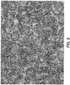
- FIG. 2 shows an image after the wax hybrid has been jetted and partially fused thereon. After the materials were jetted onto the partially fused print, the partially fused and coated print was run through an iGen3 fusing subsystem operating at 185°C and a pressure load of 100 psi in order to smooth out the wax layer.
- FIG. 3 shows a portion of a completely fused image having part of the image covered in wax-hybrid and the other part without the wax hybrid. As apparent from FIG 3 , a fairly continuous film exists over top of the toner on the portions of the image where the wax-hybrid was applied.
Landscapes
- Physics & Mathematics (AREA)
- General Physics & Mathematics (AREA)
- Life Sciences & Earth Sciences (AREA)
- Engineering & Computer Science (AREA)
- Wood Science & Technology (AREA)
- Developing Agents For Electrophotography (AREA)
- Fixing For Electrophotography (AREA)
- Control Or Security For Electrophotography (AREA)
Claims (11)
- System zum Schützen eines Bildes auf einem Substrat (18), wobei das System umfasst:eine elektrostatografische Tonerabgabestation (16), wobei der Toner von der Tonerabgabestation (16) auf einem Substrat (18) konfiguriert wird, um ein unfixiertes Tonerbild zu bilden,eine Station (21) zum teilweisen Schmelzfixieren eines Tonerbildes, wobei das unfixierte Tonerbild auf eine erste Temperatur erwärmt wird, um ein teilweise schmelzfixiertes Tonerbild zu bilden, durch Aussetzen des unfixierten Tonerbildes einer Strahlung,eine Beschichtungsstation (20), wobei eine Beschichtung von der Beschichtungsstation (20) auf das teilweise schmelzfixierte Tonerbild aufgebracht wird, um ein beschichtetes und teilweise schmelzfixiertes Tonerbild zu bilden, durch Tintenstrahltechnologie, undeine Schmelzfixierstation (19), wobei das beschichtete und teilweise schmelzfixierte Tonerbild bei einer zweiten Temperatur und Druck schmelzfixiert wird, um ein fixiertes Bild zu bilden,dadurch gekennzeichnet, dass die Strahlung aktinisch ist und die Beschichtung eine Wachs-Hybrid-Zusammensetzung ist, die eine homogene Mischung aus wenigstens einem Wachs und einem Bindemittel umfasst, wobei die Viskosität des Wachses 10 mPa·s (cP) oder weniger bei 120 °C beträgt, die Viskosität des Bindemittels 600 bis 6000 mPa·s (cP) bei 120 °C beträgt und die Viskosität des Wachs-Hybrids 20 mPa·s (cP) oder weniger bei 120 °C beträgt.
- System nach Anspruch 1, wobei Fixieröl auf dem Substrat (18) vorhanden ist.
- System nach Anspruch 2, wobei die Station (21) zum teilweisen Schmelzfixieren eines Tonerbildes eine aktinische Strahlungsquelle umfasst.
- System nach Anspruch 1, wobei das Bindemittel ein kristallines Polyesterharz ist.
- System nach Anspruch 1, wobei das Bindemittel ein Ethylen-Vinylacetat-Harz ist.
- System nach Anspruch 1, wobei das Wachs-Hybrid eine Viskosität von weniger als 12 mPa·s (cP) bei 120 °C aufweist.
- Verfahren zum Schützen eines Drucks, der Toner umfasst, wobei das Verfahren umfasst:Bilden eines unfixierten elektrostatografischen Tonerbildes auf einem Substrat (18),teilweise Schmelzfixieren des unfixierten Tonerbildes durch Erwärmen des unfixierten Tonerbildes auf eine erste Temperatur, um ein teilweise schmelzfixiertes Tonerbild auf der Oberfläche des Substrats (18) zu bilden, durch Aussetzen des unfixierten Tonerbildes einer Strahlung,Aufbringen einer Beschichtung durch Tintenstrahltechnologie auf das teilweise schmelzfixierte Tonerbild auf einer Oberfläche eines Substrats (18), um ein beschichtetes und teilweise schmelzfixiertes Tonerbild auf der Oberfläche des Substrats (18) zu bilden, und Fixieren des teilweise schmelzfixierten und beschichteten Tonerbildes, um ein gedrucktes Bild zu bilden,dadurch gekennzeichnet, dass die Strahlung aktinisch ist und die Beschichtung eine Wachs-Hybrid-Zusammensetzung ist, die eine homogene Mischung aus wenigstens einem Wachs und einem Bindemittel umfasst, wobei die Viskosität des Wachses 10 mPa·s (cP) oder weniger bei 120 °C beträgt, die Viskosität des Bindemittels innerhalb des Bereichs von 600 bis 6000 mPa·s (cP) bei 120 °C liegt, und die Viskosität des Wachs-Hybrids 20 mPa·s (cP) oder weniger bei 120 °C beträgt.
- Verfahren nach Anspruch 7, wobei das Fixieren des teilweise schmelzfixierten und beschichteten Tonerbildes das Erwärmen des beschichteten und teilweise schmelzfixierten Tonerbildes auf eine zweite Temperatur umfasst, wobei der Erwärmungsschritt das Wachs-Hybrid verwendet, um eine Schutzbarriere über dem fixierten Tonerbild zu bilden.
- Verfahren nach Anspruch 7, wobei das Fixieren das Anwenden von Wärme und Druck auf das beschichtete und teilweise schmelzfixierte Tonerbild auf der Oberfläche des Substrats (18) umfasst.
- Verfahren nach Anspruch 7, wobei das Bindemittel ein kristallines Polyesterharz ist.
- Bilderzeugungsgerät (10), das darin das System nach Anspruch 1 einschließt.
Applications Claiming Priority (1)
| Application Number | Priority Date | Filing Date | Title |
|---|---|---|---|
| US12/179,249 US7970333B2 (en) | 2008-07-24 | 2008-07-24 | System and method for protecting an image on a substrate |
Publications (3)
| Publication Number | Publication Date |
|---|---|
| EP2148248A2 EP2148248A2 (de) | 2010-01-27 |
| EP2148248A3 EP2148248A3 (de) | 2014-08-06 |
| EP2148248B1 true EP2148248B1 (de) | 2016-12-14 |
Family
ID=41136661
Family Applications (1)
| Application Number | Title | Priority Date | Filing Date |
|---|---|---|---|
| EP09165608.2A Not-in-force EP2148248B1 (de) | 2008-07-24 | 2009-07-16 | Zusammensetzung und Verfahren zur Wachsintegration in fixierten Drucken |
Country Status (6)
| Country | Link |
|---|---|
| US (1) | US7970333B2 (de) |
| EP (1) | EP2148248B1 (de) |
| JP (1) | JP5457748B2 (de) |
| KR (1) | KR101507618B1 (de) |
| CN (1) | CN101634818B (de) |
| CA (1) | CA2673132C (de) |
Families Citing this family (5)
| Publication number | Priority date | Publication date | Assignee | Title |
|---|---|---|---|---|
| US9507249B2 (en) * | 2010-05-11 | 2016-11-29 | Xerox Corporation | Non-sticky erasable media with overcoat |
| CN101976022A (zh) * | 2010-10-11 | 2011-02-16 | 珠海天威飞马打印耗材有限公司 | 图像的表面处理方法 |
| US10378143B2 (en) * | 2011-04-29 | 2019-08-13 | Tai-Her Yang | Heat reflux drying machine utilizing inlet/outlet air temperature difference to condense water |
| US9098022B2 (en) * | 2012-05-02 | 2015-08-04 | Xerox Corporation | Method and apparatus for generating differential gloss image using laser energy |
| US9228105B2 (en) * | 2012-06-12 | 2016-01-05 | Xerox Corporation | Aqueous overcoat on solid ink jet prints and methods of producing the same |
Family Cites Families (81)
| Publication number | Priority date | Publication date | Assignee | Title |
|---|---|---|---|---|
| US3590000A (en) | 1967-06-05 | 1971-06-29 | Xerox Corp | Solid developer for latent electrostatic images |
| CA1065085A (en) | 1974-05-20 | 1979-10-23 | John P. Guarino | Radiation curable coating |
| US4072592A (en) | 1974-05-20 | 1978-02-07 | Mobil Oil Corporation | Radiation curable coating |
| US4072770A (en) | 1976-05-11 | 1978-02-07 | Scm Corporation | U.V. curable poly(ester-urethane) polyacrylate polymers and wet look coatings therefrom |
| US4133909A (en) | 1977-01-26 | 1979-01-09 | Mobil Oil Corporation | Radiation curable aqueous coatings |
| US4265990A (en) | 1977-05-04 | 1981-05-05 | Xerox Corporation | Imaging system with a diamine charge transport material in a polycarbonate resin |
| US4265976A (en) | 1978-09-19 | 1981-05-05 | Celanese Corporation | Radiation-curable coated article having moisture barrier propetes |
| US4558108A (en) | 1982-12-27 | 1985-12-10 | Xerox Corporation | Aqueous suspension polymerization process |
| US5162389A (en) | 1983-10-26 | 1992-11-10 | Dow Corning Corporation | Fast ultraviolet radiation curing silicone composition having a high refractive index |
| US4585884A (en) | 1984-05-23 | 1986-04-29 | Xerox Corporation | Silylated compositions, and deuterated hydroxyl squaraine compositions and processes |
| US4584253A (en) | 1984-12-24 | 1986-04-22 | Xerox Corporation | Electrophotographic imaging system |
| US4563408A (en) | 1984-12-24 | 1986-01-07 | Xerox Corporation | Photoconductive imaging member with hydroxyaromatic antioxidant |
| US5492733A (en) | 1990-03-05 | 1996-02-20 | International Paper Company | High gloss ultraviolet curable coating |
| US5219641A (en) | 1991-02-11 | 1993-06-15 | The Standard Register Company | Thermal transfer image reception coated paper |
| DE4121131A1 (de) * | 1991-06-26 | 1993-01-07 | Zeolith Tech | Sorptionsmittelbehaelter-anordnung und sorptionsverfahren mit regenerativem waermetausch |
| US5223368A (en) | 1991-09-06 | 1993-06-29 | Xerox Corporation | Toner and developer compositions comprising aluminum charge control agent |
| US5227460A (en) | 1991-12-30 | 1993-07-13 | Xerox Corporation | Cross-linked toner resins |
| US5290654A (en) | 1992-07-29 | 1994-03-01 | Xerox Corporation | Microsuspension processes for toner compositions |
| US5278020A (en) | 1992-08-28 | 1994-01-11 | Xerox Corporation | Toner composition and processes thereof |
| US5308734A (en) | 1992-12-14 | 1994-05-03 | Xerox Corporation | Toner processes |
| US5346797A (en) | 1993-02-25 | 1994-09-13 | Xerox Corporation | Toner processes |
| US5339146A (en) * | 1993-04-01 | 1994-08-16 | Eastman Kodak Company | Method and apparatus for providing a toner image having an overcoat |
| US5346795A (en) | 1993-05-27 | 1994-09-13 | Xerox Corporation | Toner and developer compositions |
| US5348832A (en) | 1993-06-01 | 1994-09-20 | Xerox Corporation | Toner compositions |
| US5405728A (en) | 1993-06-25 | 1995-04-11 | Xerox Corporation | Toner aggregation processes |
| US5370963A (en) | 1993-06-25 | 1994-12-06 | Xerox Corporation | Toner emulsion aggregation processes |
| US5344738A (en) | 1993-06-25 | 1994-09-06 | Xerox Corporation | Process of making toner compositions |
| US5418108A (en) | 1993-06-25 | 1995-05-23 | Xerox Corporation | Toner emulsion aggregation process |
| US5403693A (en) | 1993-06-25 | 1995-04-04 | Xerox Corporation | Toner aggregation and coalescence processes |
| US5364729A (en) | 1993-06-25 | 1994-11-15 | Xerox Corporation | Toner aggregation processes |
| US5366840A (en) | 1993-08-30 | 1994-11-22 | Xerox Corporation | Liquid developer compositions |
| US5366841A (en) | 1993-09-30 | 1994-11-22 | Xerox Corporation | Toner aggregation processes |
| EP0716344A1 (de) | 1994-12-05 | 1996-06-12 | Konica Corporation | Lichtempfindliche Zusammensetzung und lithographische Druckplatte |
| US5501935A (en) | 1995-01-17 | 1996-03-26 | Xerox Corporation | Toner aggregation processes |
| US5510220A (en) | 1995-01-27 | 1996-04-23 | Xerox Corporation | Conductive developer compositions with surface additives |
| US5977210A (en) | 1995-01-30 | 1999-11-02 | Xerox Corporation | Modified emulsion aggregation processes |
| US5527658A (en) | 1995-03-13 | 1996-06-18 | Xerox Corporation | Toner aggregation processes using water insoluble transition metal containing powder |
| US5496676A (en) | 1995-03-27 | 1996-03-05 | Xerox Corporation | Toner aggregation processes |
| US5565296A (en) | 1995-07-03 | 1996-10-15 | Xerox Corporation | Coated carriers by aggregation processes |
| US5751299A (en) * | 1996-03-22 | 1998-05-12 | Lexmark International, Inc. | Combined electrophotographic and ink jet printing |
| US5585215A (en) | 1996-06-13 | 1996-12-17 | Xerox Corporation | Toner compositions |
| US5627002A (en) | 1996-08-02 | 1997-05-06 | Xerox Corporation | Liquid developer compositions with cyclodextrins |
| US5650255A (en) | 1996-09-03 | 1997-07-22 | Xerox Corporation | Low shear toner aggregation processes |
| US5723252A (en) | 1996-09-03 | 1998-03-03 | Xerox Corporation | Toner processes |
| US5650256A (en) | 1996-10-02 | 1997-07-22 | Xerox Corporation | Toner processes |
| US5683848A (en) | 1996-10-02 | 1997-11-04 | Xerox Corporation | Acrylonitrile-modified toner composition and processes |
| US5763133A (en) | 1997-03-28 | 1998-06-09 | Xerox Corporation | Toner compositions and processes |
| US5826147A (en) | 1997-06-27 | 1998-10-20 | Xerox Corporation | Electrostatic latent image development |
| US5827633A (en) | 1997-07-31 | 1998-10-27 | Xerox Corporation | Toner processes |
| US5766818A (en) | 1997-10-29 | 1998-06-16 | Xerox Corporation | Toner processes with hydrolyzable surfactant |
| US5966570A (en) | 1998-01-08 | 1999-10-12 | Xerox Corporation | Image-wise toner layer charging for image development |
| US5853944A (en) | 1998-01-13 | 1998-12-29 | Xerox Corporation | Toner processes |
| US5869215A (en) | 1998-01-13 | 1999-02-09 | Xerox Corporation | Toner compositions and processes thereof |
| US5840462A (en) | 1998-01-13 | 1998-11-24 | Xerox Corporation | Toner processes |
| US5919595A (en) | 1998-01-13 | 1999-07-06 | Xerox Corporation | Toner process with cationic salts |
| US5916725A (en) | 1998-01-13 | 1999-06-29 | Xerox Corporation | Surfactant free toner processes |
| US5910387A (en) | 1998-01-13 | 1999-06-08 | Xerox Corporation | Toner compositions with acrylonitrile and processes |
| US5863698A (en) | 1998-04-13 | 1999-01-26 | Xerox Corporation | Toner processes |
| US5858601A (en) | 1998-08-03 | 1999-01-12 | Xerox Corporation | Toner processes |
| US6187499B1 (en) | 2000-01-27 | 2001-02-13 | Xerox Corporation | Imaging apparatus |
| US6180308B1 (en) | 2000-01-27 | 2001-01-30 | Xerox Corporation | Developer compositions and processes |
| US6212347B1 (en) | 2000-01-27 | 2001-04-03 | Xerox Corporation | Imaging apparatuses and processes thereof containing a marking material with a charge acceptance additive of an aluminum complex |
| US6416916B1 (en) | 2000-03-07 | 2002-07-09 | Xerox Corporation | Toner and developer for magnetic brush development system |
| US6319647B1 (en) | 2000-03-07 | 2001-11-20 | Xerox Corporation | Toner and developer for magnetic brush development system |
| US6177221B1 (en) | 2000-03-07 | 2001-01-23 | Xerox Corporation | Carrier and developer providing offset lithography print quality |
| US6365316B1 (en) | 2000-03-07 | 2002-04-02 | Xerox Corporation | Toner and developer providing offset lithography print quality |
| US6535712B2 (en) * | 2001-07-06 | 2003-03-18 | Hewlett-Packard Company | Gloss control method and apparatus with disposable toner cartridges containing clear toners |
| US6733878B2 (en) | 2001-12-12 | 2004-05-11 | Xerox Corporation | Thermally actuated foil-less binder tape for books |
| US6808815B2 (en) | 2003-03-18 | 2004-10-26 | Xerox Corporation | Blended fluorosilicone release agent for silicone fuser members |
| JP4388754B2 (ja) * | 2003-03-25 | 2009-12-24 | 富士フイルム株式会社 | 表面処理装置およびプリンタ |
| US7279506B2 (en) * | 2004-05-05 | 2007-10-09 | Xerox Corporation | Ink jettable overprint compositions |
| US7208258B2 (en) * | 2004-06-25 | 2007-04-24 | Xerox Corporation | Blended amino functional siloxane release agents for fuser members |
| US7198875B2 (en) | 2004-06-25 | 2007-04-03 | Xerox Corporation | Amino-functional siloxane copolymer release agents for fuser members |
| US7672634B2 (en) * | 2004-11-30 | 2010-03-02 | Xerox Corporation | Addressable fusing for an integrated printing system |
| JP2007086747A (ja) * | 2005-08-22 | 2007-04-05 | Canon Inc | 画像形成装置 |
| JP4794952B2 (ja) * | 2005-09-05 | 2011-10-19 | キヤノン株式会社 | 画像形成装置及びその制御方法 |
| US7576149B2 (en) | 2006-05-31 | 2009-08-18 | Xerox Corporation | Varnish |
| JP2008058945A (ja) * | 2006-07-31 | 2008-03-13 | Ricoh Co Ltd | 画像形成方法及び画像形成装置 |
| JP4902295B2 (ja) * | 2006-08-22 | 2012-03-21 | 株式会社リコー | 画像形成装置 |
| US7657218B2 (en) * | 2006-08-22 | 2010-02-02 | Ricoh Company Ltd. | Gloss providing sheet and image formation apparatus |
| JP2008064804A (ja) * | 2006-09-04 | 2008-03-21 | Ricoh Co Ltd | 画像形成装置 |
-
2008
- 2008-07-24 US US12/179,249 patent/US7970333B2/en active Active
-
2009
- 2009-07-16 EP EP09165608.2A patent/EP2148248B1/de not_active Not-in-force
- 2009-07-17 CA CA2673132A patent/CA2673132C/en not_active Expired - Fee Related
- 2009-07-21 JP JP2009170467A patent/JP5457748B2/ja not_active Expired - Fee Related
- 2009-07-23 CN CN200910159918XA patent/CN101634818B/zh not_active Expired - Fee Related
- 2009-07-23 KR KR20090067267A patent/KR101507618B1/ko not_active Expired - Fee Related
Non-Patent Citations (1)
| Title |
|---|
| None * |
Also Published As
| Publication number | Publication date |
|---|---|
| CN101634818A (zh) | 2010-01-27 |
| KR20100011927A (ko) | 2010-02-03 |
| KR101507618B1 (ko) | 2015-04-01 |
| CA2673132C (en) | 2013-09-24 |
| US20100021217A1 (en) | 2010-01-28 |
| CA2673132A1 (en) | 2010-01-24 |
| JP2010033052A (ja) | 2010-02-12 |
| JP5457748B2 (ja) | 2014-04-02 |
| EP2148248A2 (de) | 2010-01-27 |
| US7970333B2 (en) | 2011-06-28 |
| EP2148248A3 (de) | 2014-08-06 |
| CN101634818B (zh) | 2013-01-23 |
Similar Documents
| Publication | Publication Date | Title |
|---|---|---|
| US7641982B2 (en) | Radiation curable composition | |
| US8039187B2 (en) | Curable toner compositions and processes | |
| EP2148248B1 (de) | Zusammensetzung und Verfahren zur Wachsintegration in fixierten Drucken | |
| US9372425B2 (en) | Curable sublimation toner and sublimation transfer process using same | |
| CA2506020C (en) | Overprint compositions for xerographic prints | |
| US8699892B2 (en) | Method of evaluating electrophotographic overcoatability of composition, electrophotographic overcoat composition, electrophotographic method, and electrophotographic apparatus | |
| US8067142B2 (en) | Coating, system and method for conditioning prints | |
| US6127081A (en) | Developing agent and image forming apparatus | |
| US8383309B2 (en) | Preparation of sublimation colorant dispersion | |
| US20070048653A1 (en) | Image forming method and image-forming apparatus using the same | |
| US9052618B2 (en) | Overcoat composition for electrophotography, electrophotographic image forming method and electrophotographic image forming apparatus | |
| JPH07319198A (ja) | 画像上に高光沢な保護コーティングを形成する方法 | |
| US20060051686A1 (en) | Image structure, recording medium, image forming apparatus and post-process device | |
| US8168361B2 (en) | Curable toner compositions and processes | |
| WO2008047775A1 (fr) | Toner pour l'électrophotographie | |
| JP2010133988A (ja) | 画像形成装置 | |
| JP2011203584A (ja) | 静電荷像現像トナー、静電荷像現像トナーの製造方法、画像形成方法、及び、画像形成装置 | |
| US20060286475A1 (en) | Developing agent and image forming apparatus using the same | |
| JP6781009B2 (ja) | 電子写真用トナー | |
| JPH05197184A (ja) | 電子写真用被転写フィルム | |
| JPH05307334A (ja) | 定着装置 | |
| JP2012042644A (ja) | 定着方法、画像形成方法及び画像形成装置 |
Legal Events
| Date | Code | Title | Description |
|---|---|---|---|
| PUAI | Public reference made under article 153(3) epc to a published international application that has entered the european phase |
Free format text: ORIGINAL CODE: 0009012 |
|
| AK | Designated contracting states |
Kind code of ref document: A2 Designated state(s): AT BE BG CH CY CZ DE DK EE ES FI FR GB GR HR HU IE IS IT LI LT LU LV MC MK MT NL NO PL PT RO SE SI SK SM TR |
|
| AX | Request for extension of the european patent |
Extension state: AL BA RS |
|
| PUAL | Search report despatched |
Free format text: ORIGINAL CODE: 0009013 |
|
| AK | Designated contracting states |
Kind code of ref document: A3 Designated state(s): AT BE BG CH CY CZ DE DK EE ES FI FR GB GR HR HU IE IS IT LI LT LU LV MC MK MT NL NO PL PT RO SE SI SK SM TR |
|
| AX | Request for extension of the european patent |
Extension state: AL BA RS |
|
| RIC1 | Information provided on ipc code assigned before grant |
Ipc: G03G 15/20 20060101ALN20140701BHEP Ipc: G03G 15/00 20060101AFI20140701BHEP |
|
| RIN1 | Information on inventor provided before grant (corrected) |
Inventor name: ZWARTZ, EDWARD G. Inventor name: MCANENEY, T. BRIAN Inventor name: ANDERSON, CHRISTINE Inventor name: WAGNER, CHRISTOPHER A. Inventor name: DRAPPEL, STEPHAN V. |
|
| 17P | Request for examination filed |
Effective date: 20150206 |
|
| RBV | Designated contracting states (corrected) |
Designated state(s): AT BE BG CH CY CZ DE DK EE ES FI FR GB GR HR HU IE IS IT LI LT LU LV MC MK MT NL NO PL PT RO SE SI SK SM TR |
|
| GRAP | Despatch of communication of intention to grant a patent |
Free format text: ORIGINAL CODE: EPIDOSNIGR1 |
|
| RIC1 | Information provided on ipc code assigned before grant |
Ipc: G03G 15/00 20060101AFI20160726BHEP Ipc: G03G 15/20 20060101ALN20160726BHEP |
|
| RIC1 | Information provided on ipc code assigned before grant |
Ipc: G03G 15/20 20060101ALN20160811BHEP Ipc: G03G 15/00 20060101AFI20160811BHEP |
|
| INTG | Intention to grant announced |
Effective date: 20160824 |
|
| GRAS | Grant fee paid |
Free format text: ORIGINAL CODE: EPIDOSNIGR3 |
|
| GRAA | (expected) grant |
Free format text: ORIGINAL CODE: 0009210 |
|
| AK | Designated contracting states |
Kind code of ref document: B1 Designated state(s): AT BE BG CH CY CZ DE DK EE ES FI FR GB GR HR HU IE IS IT LI LT LU LV MC MK MT NL NO PL PT RO SE SI SK SM TR |
|
| REG | Reference to a national code |
Ref country code: GB Ref legal event code: FG4D |
|
| REG | Reference to a national code |
Ref country code: CH Ref legal event code: EP |
|
| REG | Reference to a national code |
Ref country code: IE Ref legal event code: FG4D |
|
| REG | Reference to a national code |
Ref country code: AT Ref legal event code: REF Ref document number: 854120 Country of ref document: AT Kind code of ref document: T Effective date: 20170115 |
|
| REG | Reference to a national code |
Ref country code: DE Ref legal event code: R096 Ref document number: 602009043014 Country of ref document: DE |
|
| PG25 | Lapsed in a contracting state [announced via postgrant information from national office to epo] |
Ref country code: LV Free format text: LAPSE BECAUSE OF FAILURE TO SUBMIT A TRANSLATION OF THE DESCRIPTION OR TO PAY THE FEE WITHIN THE PRESCRIBED TIME-LIMIT Effective date: 20161214 |
|
| REG | Reference to a national code |
Ref country code: LT Ref legal event code: MG4D |
|
| REG | Reference to a national code |
Ref country code: NL Ref legal event code: MP Effective date: 20161214 |
|
| PG25 | Lapsed in a contracting state [announced via postgrant information from national office to epo] |
Ref country code: NO Free format text: LAPSE BECAUSE OF FAILURE TO SUBMIT A TRANSLATION OF THE DESCRIPTION OR TO PAY THE FEE WITHIN THE PRESCRIBED TIME-LIMIT Effective date: 20170314 Ref country code: SE Free format text: LAPSE BECAUSE OF FAILURE TO SUBMIT A TRANSLATION OF THE DESCRIPTION OR TO PAY THE FEE WITHIN THE PRESCRIBED TIME-LIMIT Effective date: 20161214 Ref country code: GR Free format text: LAPSE BECAUSE OF FAILURE TO SUBMIT A TRANSLATION OF THE DESCRIPTION OR TO PAY THE FEE WITHIN THE PRESCRIBED TIME-LIMIT Effective date: 20170315 Ref country code: LT Free format text: LAPSE BECAUSE OF FAILURE TO SUBMIT A TRANSLATION OF THE DESCRIPTION OR TO PAY THE FEE WITHIN THE PRESCRIBED TIME-LIMIT Effective date: 20161214 |
|
| REG | Reference to a national code |
Ref country code: AT Ref legal event code: MK05 Ref document number: 854120 Country of ref document: AT Kind code of ref document: T Effective date: 20161214 |
|
| PG25 | Lapsed in a contracting state [announced via postgrant information from national office to epo] |
Ref country code: FI Free format text: LAPSE BECAUSE OF FAILURE TO SUBMIT A TRANSLATION OF THE DESCRIPTION OR TO PAY THE FEE WITHIN THE PRESCRIBED TIME-LIMIT Effective date: 20161214 Ref country code: HR Free format text: LAPSE BECAUSE OF FAILURE TO SUBMIT A TRANSLATION OF THE DESCRIPTION OR TO PAY THE FEE WITHIN THE PRESCRIBED TIME-LIMIT Effective date: 20161214 |
|
| REG | Reference to a national code |
Ref country code: FR Ref legal event code: PLFP Year of fee payment: 9 |
|
| PG25 | Lapsed in a contracting state [announced via postgrant information from national office to epo] |
Ref country code: NL Free format text: LAPSE BECAUSE OF FAILURE TO SUBMIT A TRANSLATION OF THE DESCRIPTION OR TO PAY THE FEE WITHIN THE PRESCRIBED TIME-LIMIT Effective date: 20161214 |
|
| PG25 | Lapsed in a contracting state [announced via postgrant information from national office to epo] |
Ref country code: IS Free format text: LAPSE BECAUSE OF FAILURE TO SUBMIT A TRANSLATION OF THE DESCRIPTION OR TO PAY THE FEE WITHIN THE PRESCRIBED TIME-LIMIT Effective date: 20170414 Ref country code: RO Free format text: LAPSE BECAUSE OF FAILURE TO SUBMIT A TRANSLATION OF THE DESCRIPTION OR TO PAY THE FEE WITHIN THE PRESCRIBED TIME-LIMIT Effective date: 20161214 Ref country code: CZ Free format text: LAPSE BECAUSE OF FAILURE TO SUBMIT A TRANSLATION OF THE DESCRIPTION OR TO PAY THE FEE WITHIN THE PRESCRIBED TIME-LIMIT Effective date: 20161214 Ref country code: EE Free format text: LAPSE BECAUSE OF FAILURE TO SUBMIT A TRANSLATION OF THE DESCRIPTION OR TO PAY THE FEE WITHIN THE PRESCRIBED TIME-LIMIT Effective date: 20161214 Ref country code: SK Free format text: LAPSE BECAUSE OF FAILURE TO SUBMIT A TRANSLATION OF THE DESCRIPTION OR TO PAY THE FEE WITHIN THE PRESCRIBED TIME-LIMIT Effective date: 20161214 |
|
| PG25 | Lapsed in a contracting state [announced via postgrant information from national office to epo] |
Ref country code: BE Free format text: LAPSE BECAUSE OF FAILURE TO SUBMIT A TRANSLATION OF THE DESCRIPTION OR TO PAY THE FEE WITHIN THE PRESCRIBED TIME-LIMIT Effective date: 20161214 Ref country code: BG Free format text: LAPSE BECAUSE OF FAILURE TO SUBMIT A TRANSLATION OF THE DESCRIPTION OR TO PAY THE FEE WITHIN THE PRESCRIBED TIME-LIMIT Effective date: 20170314 Ref country code: SM Free format text: LAPSE BECAUSE OF FAILURE TO SUBMIT A TRANSLATION OF THE DESCRIPTION OR TO PAY THE FEE WITHIN THE PRESCRIBED TIME-LIMIT Effective date: 20161214 Ref country code: PL Free format text: LAPSE BECAUSE OF FAILURE TO SUBMIT A TRANSLATION OF THE DESCRIPTION OR TO PAY THE FEE WITHIN THE PRESCRIBED TIME-LIMIT Effective date: 20161214 Ref country code: PT Free format text: LAPSE BECAUSE OF FAILURE TO SUBMIT A TRANSLATION OF THE DESCRIPTION OR TO PAY THE FEE WITHIN THE PRESCRIBED TIME-LIMIT Effective date: 20170414 Ref country code: AT Free format text: LAPSE BECAUSE OF FAILURE TO SUBMIT A TRANSLATION OF THE DESCRIPTION OR TO PAY THE FEE WITHIN THE PRESCRIBED TIME-LIMIT Effective date: 20161214 Ref country code: IT Free format text: LAPSE BECAUSE OF FAILURE TO SUBMIT A TRANSLATION OF THE DESCRIPTION OR TO PAY THE FEE WITHIN THE PRESCRIBED TIME-LIMIT Effective date: 20161214 Ref country code: ES Free format text: LAPSE BECAUSE OF FAILURE TO SUBMIT A TRANSLATION OF THE DESCRIPTION OR TO PAY THE FEE WITHIN THE PRESCRIBED TIME-LIMIT Effective date: 20161214 |
|
| REG | Reference to a national code |
Ref country code: DE Ref legal event code: R097 Ref document number: 602009043014 Country of ref document: DE |
|
| PLBE | No opposition filed within time limit |
Free format text: ORIGINAL CODE: 0009261 |
|
| STAA | Information on the status of an ep patent application or granted ep patent |
Free format text: STATUS: NO OPPOSITION FILED WITHIN TIME LIMIT |
|
| 26N | No opposition filed |
Effective date: 20170915 |
|
| PG25 | Lapsed in a contracting state [announced via postgrant information from national office to epo] |
Ref country code: DK Free format text: LAPSE BECAUSE OF FAILURE TO SUBMIT A TRANSLATION OF THE DESCRIPTION OR TO PAY THE FEE WITHIN THE PRESCRIBED TIME-LIMIT Effective date: 20161214 |
|
| PG25 | Lapsed in a contracting state [announced via postgrant information from national office to epo] |
Ref country code: SI Free format text: LAPSE BECAUSE OF FAILURE TO SUBMIT A TRANSLATION OF THE DESCRIPTION OR TO PAY THE FEE WITHIN THE PRESCRIBED TIME-LIMIT Effective date: 20161214 |
|
| REG | Reference to a national code |
Ref country code: CH Ref legal event code: PL |
|
| REG | Reference to a national code |
Ref country code: IE Ref legal event code: MM4A |
|
| PG25 | Lapsed in a contracting state [announced via postgrant information from national office to epo] |
Ref country code: CH Free format text: LAPSE BECAUSE OF NON-PAYMENT OF DUE FEES Effective date: 20170731 Ref country code: LI Free format text: LAPSE BECAUSE OF NON-PAYMENT OF DUE FEES Effective date: 20170731 Ref country code: IE Free format text: LAPSE BECAUSE OF NON-PAYMENT OF DUE FEES Effective date: 20170716 |
|
| REG | Reference to a national code |
Ref country code: FR Ref legal event code: PLFP Year of fee payment: 10 |
|
| PG25 | Lapsed in a contracting state [announced via postgrant information from national office to epo] |
Ref country code: LU Free format text: LAPSE BECAUSE OF NON-PAYMENT OF DUE FEES Effective date: 20170716 |
|
| PG25 | Lapsed in a contracting state [announced via postgrant information from national office to epo] |
Ref country code: MT Free format text: LAPSE BECAUSE OF NON-PAYMENT OF DUE FEES Effective date: 20170716 |
|
| PG25 | Lapsed in a contracting state [announced via postgrant information from national office to epo] |
Ref country code: MC Free format text: LAPSE BECAUSE OF FAILURE TO SUBMIT A TRANSLATION OF THE DESCRIPTION OR TO PAY THE FEE WITHIN THE PRESCRIBED TIME-LIMIT Effective date: 20161214 Ref country code: HU Free format text: LAPSE BECAUSE OF FAILURE TO SUBMIT A TRANSLATION OF THE DESCRIPTION OR TO PAY THE FEE WITHIN THE PRESCRIBED TIME-LIMIT; INVALID AB INITIO Effective date: 20090716 |
|
| PG25 | Lapsed in a contracting state [announced via postgrant information from national office to epo] |
Ref country code: CY Free format text: LAPSE BECAUSE OF NON-PAYMENT OF DUE FEES Effective date: 20161214 |
|
| PG25 | Lapsed in a contracting state [announced via postgrant information from national office to epo] |
Ref country code: MK Free format text: LAPSE BECAUSE OF FAILURE TO SUBMIT A TRANSLATION OF THE DESCRIPTION OR TO PAY THE FEE WITHIN THE PRESCRIBED TIME-LIMIT Effective date: 20161214 |
|
| PG25 | Lapsed in a contracting state [announced via postgrant information from national office to epo] |
Ref country code: TR Free format text: LAPSE BECAUSE OF FAILURE TO SUBMIT A TRANSLATION OF THE DESCRIPTION OR TO PAY THE FEE WITHIN THE PRESCRIBED TIME-LIMIT Effective date: 20161214 |
|
| PGFP | Annual fee paid to national office [announced via postgrant information from national office to epo] |
Ref country code: FR Payment date: 20200623 Year of fee payment: 12 |
|
| PGFP | Annual fee paid to national office [announced via postgrant information from national office to epo] |
Ref country code: GB Payment date: 20200624 Year of fee payment: 12 |
|
| PGFP | Annual fee paid to national office [announced via postgrant information from national office to epo] |
Ref country code: DE Payment date: 20200622 Year of fee payment: 12 |
|
| REG | Reference to a national code |
Ref country code: DE Ref legal event code: R119 Ref document number: 602009043014 Country of ref document: DE |
|
| GBPC | Gb: european patent ceased through non-payment of renewal fee |
Effective date: 20210716 |
|
| PG25 | Lapsed in a contracting state [announced via postgrant information from national office to epo] |
Ref country code: GB Free format text: LAPSE BECAUSE OF NON-PAYMENT OF DUE FEES Effective date: 20210716 Ref country code: DE Free format text: LAPSE BECAUSE OF NON-PAYMENT OF DUE FEES Effective date: 20220201 |
|
| PG25 | Lapsed in a contracting state [announced via postgrant information from national office to epo] |
Ref country code: FR Free format text: LAPSE BECAUSE OF NON-PAYMENT OF DUE FEES Effective date: 20210731 |