EP2147635A1 - Vorrichtung und Verfahren für die Beobachtung eines Gegenstandes - Google Patents
Vorrichtung und Verfahren für die Beobachtung eines Gegenstandes Download PDFInfo
- Publication number
- EP2147635A1 EP2147635A1 EP09008979A EP09008979A EP2147635A1 EP 2147635 A1 EP2147635 A1 EP 2147635A1 EP 09008979 A EP09008979 A EP 09008979A EP 09008979 A EP09008979 A EP 09008979A EP 2147635 A1 EP2147635 A1 EP 2147635A1
- Authority
- EP
- European Patent Office
- Prior art keywords
- light
- subject
- scattering
- optical modulation
- section
- Prior art date
- Legal status (The legal status is an assumption and is not a legal conclusion. Google has not performed a legal analysis and makes no representation as to the accuracy of the status listed.)
- Granted
Links
Images


Classifications
-
- A—HUMAN NECESSITIES
- A61—MEDICAL OR VETERINARY SCIENCE; HYGIENE
- A61B—DIAGNOSIS; SURGERY; IDENTIFICATION
- A61B1/00—Instruments for performing medical examinations of the interior of cavities or tubes of the body by visual or photographical inspection, e.g. endoscopes; Illuminating arrangements therefor
- A61B1/00064—Constructional details of the endoscope body
- A61B1/00071—Insertion part of the endoscope body
- A61B1/0008—Insertion part of the endoscope body characterised by distal tip features
- A61B1/00096—Optical elements
-
- A—HUMAN NECESSITIES
- A61—MEDICAL OR VETERINARY SCIENCE; HYGIENE
- A61B—DIAGNOSIS; SURGERY; IDENTIFICATION
- A61B1/00—Instruments for performing medical examinations of the interior of cavities or tubes of the body by visual or photographical inspection, e.g. endoscopes; Illuminating arrangements therefor
- A61B1/04—Instruments for performing medical examinations of the interior of cavities or tubes of the body by visual or photographical inspection, e.g. endoscopes; Illuminating arrangements therefor combined with photographic or television appliances
- A61B1/041—Capsule endoscopes for imaging
-
- A—HUMAN NECESSITIES
- A61—MEDICAL OR VETERINARY SCIENCE; HYGIENE
- A61B—DIAGNOSIS; SURGERY; IDENTIFICATION
- A61B1/00—Instruments for performing medical examinations of the interior of cavities or tubes of the body by visual or photographical inspection, e.g. endoscopes; Illuminating arrangements therefor
- A61B1/04—Instruments for performing medical examinations of the interior of cavities or tubes of the body by visual or photographical inspection, e.g. endoscopes; Illuminating arrangements therefor combined with photographic or television appliances
- A61B1/045—Control thereof
-
- A—HUMAN NECESSITIES
- A61—MEDICAL OR VETERINARY SCIENCE; HYGIENE
- A61B—DIAGNOSIS; SURGERY; IDENTIFICATION
- A61B5/00—Measuring for diagnostic purposes; Identification of persons
- A61B5/0059—Measuring for diagnostic purposes; Identification of persons using light, e.g. diagnosis by transillumination, diascopy, fluorescence
- A61B5/0082—Measuring for diagnostic purposes; Identification of persons using light, e.g. diagnosis by transillumination, diascopy, fluorescence adapted for particular medical purposes
- A61B5/0084—Measuring for diagnostic purposes; Identification of persons using light, e.g. diagnosis by transillumination, diascopy, fluorescence adapted for particular medical purposes for introduction into the body, e.g. by catheters
-
- G—PHYSICS
- G01—MEASURING; TESTING
- G01N—INVESTIGATING OR ANALYSING MATERIALS BY DETERMINING THEIR CHEMICAL OR PHYSICAL PROPERTIES
- G01N21/00—Investigating or analysing materials by the use of optical means, i.e. using sub-millimetre waves, infrared, visible or ultraviolet light
- G01N21/17—Systems in which incident light is modified in accordance with the properties of the material investigated
- G01N21/47—Scattering, i.e. diffuse reflection
- G01N21/4738—Diffuse reflection, e.g. also for testing fluids, fibrous materials
- G01N21/474—Details of optical heads therefor, e.g. using optical fibres
-
- G—PHYSICS
- G01—MEASURING; TESTING
- G01N—INVESTIGATING OR ANALYSING MATERIALS BY DETERMINING THEIR CHEMICAL OR PHYSICAL PROPERTIES
- G01N21/00—Investigating or analysing materials by the use of optical means, i.e. using sub-millimetre waves, infrared, visible or ultraviolet light
- G01N21/17—Systems in which incident light is modified in accordance with the properties of the material investigated
- G01N21/47—Scattering, i.e. diffuse reflection
- G01N21/4788—Diffraction
-
- G—PHYSICS
- G01—MEASURING; TESTING
- G01N—INVESTIGATING OR ANALYSING MATERIALS BY DETERMINING THEIR CHEMICAL OR PHYSICAL PROPERTIES
- G01N21/00—Investigating or analysing materials by the use of optical means, i.e. using sub-millimetre waves, infrared, visible or ultraviolet light
- G01N21/17—Systems in which incident light is modified in accordance with the properties of the material investigated
- G01N21/47—Scattering, i.e. diffuse reflection
- G01N2021/4704—Angular selective
- G01N2021/4711—Multiangle measurement
- G01N2021/4716—Using a ring of sensors, or a combination of diaphragm and sensors; Annular sensor
-
- G—PHYSICS
- G02—OPTICS
- G02B—OPTICAL ELEMENTS, SYSTEMS OR APPARATUS
- G02B23/00—Telescopes, e.g. binoculars; Periscopes; Instruments for viewing the inside of hollow bodies; Viewfinders; Optical aiming or sighting devices
- G02B23/24—Instruments or systems for viewing the inside of hollow bodies, e.g. fibrescopes
- G02B23/2407—Optical details
Definitions
- the present invention relates to a subject observation apparatus and a subject observation method, and more particularly to a subject observation apparatus and a subject observation method for observing a subject based on a modulated light obtained by modulating a scattered light from the subject.
- Japanese Patent Application Laid-Open Publication No. 11-258167 discloses a technique for a method of inspecting a defection in a glass tube.
- a laser light is almost vertically irradiated onto an outer surface or an inner surface of a glass tube to detect intensity and angle distribution of a scattering light caused by the laser light reflected from the glass tube, and based on the detected intensity and angle distribution of the scattering light, the defection size of the glass tube is determined and a bubble streak is discriminated from an extraneous substance.
- Japanese Patent Application Laid-Open Publication No. 2006-341078 discloses a biological observation apparatus having a configuration for generating a narrowband spectral image in which structure of capillary vessels of a mucosa surface layer is highlighted.
- living tissues are generally classified into normal tissues and tumor tissues according to a degree of nuclear atypia or structural atypia of cells. That is, if the degree of nuclear atypia or structural atypia of cells can be directly observed, the observation is considered to be very helpful when identifying tumor tissues showing little characteristic finding such as an early stage esophagus cancer, for example.
- the technique disclosed in the Japanese Patent Application Laid-Open Publication No. 11-258167 is used for determining the size of defection of the glass tube and discriminating the bubble streaks from extraneous substance, so that the technique cannot be used for the purpose of observing the degree of nuclear atypia or structural atypia of cells.
- the biological observation apparatus disclosed in the Japanese Patent Application Laid-Open Publication No. 2006-341078 has such a problem that the apparatus cannot provide a useful effect when observing a tumor tissues which have no influence on the capillary vessels, and as a result, the apparatus cannot identify the tumor tissues which shows little characteristic finding.
- the present invention has been achieved in view of above-described circumstances, and an object of the present invention is to provide a subject observation apparatus and a subject observation method capable of identifying a region exhibiting a desired scattering characteristic in a scattering medium including a plurality of regions each of which having different scattering characteristics.
- an object of the present invention is to provide a subject observation apparatus and a subject observation method capable of identifying a region exhibiting a desired scattering characteristic in a scattering medium including a plurality of regions each having a different scattering characteristic, with simple operation.
- a subject observation apparatus includes: a light-emitting section for emitting a light to a subject; an optical modulation section for detecting a scattering angle of a return light from the subject and performing optical modulation on the return light in accordance with the scattering angle; and a signal output section for generating a signal to show a state of light scattering in the subject based on the light subjected to the optical modulation by the optical modulation section, and outputting the generated signal.
- a subject observation apparatus includes: a light-emitting section for emitting a light to a subject; an optical modulation section for detecting a scattering angle of a return light from the subject and performing optical modulation on the return light in accordance with the scattering angle; and an image pickup device for picking up an image of the subject based on the light subjected to the optical modulation by the optical modulation section.
- a subject observation method according to the present invention includes:
- a subject observation method according to the present invention includes:
- FIG. 1 is a view schematically showing a scattering characteristic when a light is incident on a scattering object.
- FIG. 2 is a view showing an example of a subject including a plurality of regions each having a different scattering characteristic.
- FIG. 3 is a view showing intensity distributions of scattering lights corresponding to scattering angles in two different scattering media.
- a scattering angle ⁇ is defined as a value which is expressed as 0° ⁇ ⁇ ⁇ 180°
- a subject 102 including a two-layer structure made up of an upper layer and a lower layer as shown in FIG. 2 .
- An absorbing object 102a which exhibits a strong light-absorption characteristic, uniformly exists in the lower layer of the subject 102.
- the upper layer of the subject 102 has a structure divided into three regions, that is, left, right, and central regions.
- a first scattering medium 102b which exhibits a relatively weak forward-scattering characteristic, exists in the left and right regions
- a second scattering medium 102c which exhibits a relatively strong forward-scattering characteristic, exists in the central region.
- the distribution of the scattering angle ⁇ corresponding to the intensity of the scattering light (return light) from the scattering medium 102b is as shown by the curve Db in FIG. 3 .
- the distribution of the scattering angle ⁇ corresponding to the intensity of the scattering light (return light) from the scattering medium 102c is as shown by the curve Dc in FIG. 3 .
- the subject 102 is a living tissue
- a large part of the light incident on the subject 102 is multiply-scattered inside the living tissue.
- observation is performed assuming that the light is emitted by strong forward-scattering from the scattering object located immediately below the surface of the living tissue. That is, observation performed on the light multiply-scattered by the living tissue is equivalent to the observation performed on the forward-scattering light emitted from the scattering object located immediately below the surface of the living tissue.
- each of the first scattering medium 102b and the second scattering medium 102c has a different forward-scattering characteristic, so that the distributions of the scattering angle ⁇ corresponding to the intensity of the scattering light (return light) are different from each other.
- FIGS. 4 to 13 relate to the first embodiment of the present invention.
- FIG. 4 is a view showing a configuration of a main part of the subject observation apparatus according to the first embodiment of the present invention.
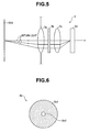
- FIG. 5 is a view showing an example of a specific configuration of an image pickup section included in the subject observation apparatus according to the first embodiment of the present invention.
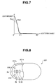
- FIG. 6 is a view showing an example of a specific configuration of an optical modulator included in the image pickup section in FIG. 5 .
- FIG. 7 is a view showing a modulation result in a case where optical modulation has been performed by the optical modulator in FIG. 6 on the scattering lights having the scattering angle distributions in FIG. 3 .
- FIG. 4 is a view showing a configuration of a main part of the subject observation apparatus according to the first embodiment of the present invention.
- FIG. 5 is a view showing an example of a specific configuration of an image pickup section included in the subject observation apparatus according to the first embodiment of the present invention.
- FIG. 6 is a view
- FIG. 8 is a view showing an example in a case where a part of the configuration of the subject observation apparatus according to the first embodiment of the present invention is applied to a capsule medical apparatus.
- FIG. 9 is a view showing an example when a part of the configuration of the subject observation apparatus according to the first embodiment of the present invention is applied to a rigid endoscope.
- FIG. 10 is a view showing an example when a part of the configuration of the subject observation apparatus according to the first embodiment of the present invention is combined with a configuration for polarized imaging.
- FIG. 11 is a view showing an exemplary configuration of an image pickup section including two image pickup systems, an image pickup system with an optical modulator and an image pickup system without an optical modulator.
- FIG 12 is a view showing an exemplary configuration of an image pickup section including an optical modulator which is insertable/retractable onto and from an optical path of the light emitted from a first optical system.
- FIG. 13 is a view showing an exemplary configuration in which an area ratio of a light-shielding portion and a light-transmitting portion in the optical modulator can be changed.
- the subject observation apparatus 1 includes: an illumination section 2 that emits illumination light to a subject 102A; an image pickup section 3 that generates an image pickup signal by photoelectrically converting the optically modulated return light of the illumination light and outputs the generated image pickup signal; a signal processing section 4 that generates a video signal by signal-processing the image pickup signal and outputs the generated video signal; and a display section 5 that displays an image of the subject 102A based on the video signal.
- the subject 102A has at least an inner structure in which the first scattering medium 102b and the second scattering medium 102c are arranged in a random manner.
- the illumination light emitted from the illumination section 2 may be either a broadband light or a narrowband light.
- the image pickup section 3 includes: a first optical system 3a that emits an incident return light as a parallel light having an angle corresponding to an incident angle at which the return light enters the first optical system 3a itself; an optical modulator 3b that optically modulates the parallel light emitted from the first optical system 3a; a second optical system 3c that forms an image of the light modulated by the optical modulator 3b; and an image pickup device 3d that generates an image pickup signal by photoelectrically converting the light whose image has been formed by the second optical system 3c, and outputs the generated image pickup signal.
- an optical modulation section in the present embodiment is configured of the first optical system 3a and the optical modulator 3b.
- the first optical system 3a and the second optical system 3c are configured of Fresnel lenses having approximately the same diameter.
- the first optical system 3a as long as it can emit the incident return light as a parallel light, is not limited to one configured of a single Fresnel lens, and may be configured by combining a plurality of lenses.
- the optical modulator 3b as the optical modulation section is formed in a disk shape having approximately the same diameter as those of the first optical system 3a and the second optical system 3c, for example.
- the optical modulator 3b is formed by including a light-shielding portion 3b1, the light transmission rate of which is substantially zero, and a light-transmitting portion 3b2, the light transmission rate of which is substantially 100%.
- the optical modulator 3b may be configured of a black plate having a hole as the light-transmitting portion 32b, for example, or may be configured of a liquid crystal shutter capable of changing the light transmission rates (optical characteristics) of the light-shielding portion 3b1 and the light-transmitting portion 3b2.
- the optical modulator 3b is not required to be formed of a specific material, so that the optical modulator 3b may be formed of a glass plate or a metal plate, for example.
- Illumination light emitted from the illumination section 2 as a light-emitting section is multiply-scattered in the subject 102A, and thereafter being incident on the first optical system 3a as return lights.
- the return lights are incident on the first optical system 3a as the lights each having the scattering angle equal to or larger than zero degree and smaller than 90 degrees.
- the return lights when the return lights are from the first scattering medium 102b, the return lights have the scattering angle distribution shown by the curve Db in FIG. 3 .
- the return lights when the return lights are from the second scattering medium 102c, the return lights have the scattering angle distribution shown by the curve Dc in FIG. 3 .
- the return lights which are incident on the first optical system 3a are emitted as parallel lights, and thereafter optically modulated by the optical modulator 3b.
- the return lights whose incident angles with respect to the first optical system 3a are equal to or larger than zero degree and equal to or smaller than a predetermined angle ⁇ 1 pass through the light-transmitting portion 3b2 of the optical modulator 3b, so that the lights are emitted to the second optical system 3c with the intensities of the lights substantially maintained.
- the return lights whose incident angles with respect to the first optical system 3a are larger than the predetermined angle ⁇ 1 and smaller than 90 degrees are shielded by the light-shielding portion 3b1 of the optical modulator 3b.
- the optical modulator 3b performs optical modulation on the parallel lights emitted from the first optical system 3a so as to emit the lights to the second optical system 3c with the intensities of the lights substantially maintained when the scattering angles of the return lights are equal to or larger than zero degree and equal to or smaller than the predetermined angle ⁇ 1, and shield the lights when the scattering angles of the return lights are larger than the predetermined angle ⁇ 1 and smaller than 90 degrees.
- the scattering angle distributions corresponding to the intensities of the return lights before and after passing through the first optical system 3a and the optical modulator 3b change from the distributions shown by the curves Db and Dc in FIG. 3 to the distributions shown by the curves Dbm and Dcm in FIG. 7 .
- the parallel lights subjected to the optical modulation by the optical modulator 3b are image-formed by the second optical system 3c, photoelectrically converted by the image pickup device 3d, and thereafter being outputted to the signal processing section 4 as an image pickup signal.
- the image pickup signal outputted from the image pickup device 3d as a signal output section is converted into a video signal by the signal processing section 4, and thereafter being outputted on the display section 5.
- an image of the subject 102A in which a difference in the light intensities between the curve Dbm and the curve Dcm in FIG. 7 is exhibited as a difference in brightness, is outputted on the display section 5.
- the subject 102A is a living tissue
- the first scattering medium 102b is a normal tissue
- the second scattering medium 102c is a tumor tissue.
- the second scattering medium 102c has a stronger forward-scattering characteristic than that of the first scattering medium 102b. Accordingly, in the image of the subject 102A outputted on the display section 5, the portion where a tumor tissue exists looks brighter than other portions. That is, when the endoscope and the like provided with the image pickup section 3 having the above-described configuration is used, it is possible to easily identify the region where a tumor tissue showing little characteristic finding exists.
- the subject observation apparatus 1 of the present embodiment can identify the region where a desired scattering characteristic is exhibited in the scattering medium including a plurality of regions each having a different scattering characteristic.
- the apparatus may be used not only for the purpose of discriminating between a normal tissue and a tumor tissue in observation of a living tissue, but also for the purpose of discriminating between a normal portion and abnormal portion in a quality inspection.
- the optical modulator 3b is not limited to one having the above-described configuration and working.
- the optical modulator 3b may optically modulate the parallel lights emitted from the first optical system 3a so as to shield the lights when the scattering angles of the return lights are equal to or larger than zero degree and equal to or smaller than the predetermined angle ⁇ 1, and emit the lights to the second optical system 3c with the intensities of the lights substantially maintained, when the scattering angles of the return lights are larger than the predetermined angle ⁇ 1 and smaller than 90 degrees.
- the configuration of the subject observation apparatus 1 of the present embodiment can be applied to a capsule medical apparatus, for example.
- a capsule medical apparatus 201 shown in FIG. 8 includes: an exterior member 201a having a light-shielding effect, a cross section of which is U-shaped; and an approximately hemispherically-shaped cover member 201b made of a transparent member, which is water-tightly mounted with adhesive to an opening end of a distal end side of the exterior member 201a.
- the optical modulator 3b In a hollow portion inside the exterior member 201a are provided the optical modulator 3b, the second optical system 3c, and the image pickup device 3d. On the other hand, in a hollow portion inside the cover member 201b are provided the first optical system 3a and an LED 202 having a function as a light-emitting section.
- the configuration of the subject observation apparatus 1 according to the present embodiment can be applied to a rigid endoscope, for example.
- a rigid endoscope 301 shown in FIG. 9 is configured by including an elongated insertion portion 301a and an eyepiece portion 301b.
- a first optical system 3a Inside the insertion portion 301a are arranged in the following order from the distal end side: a first optical system 3a; an optical modulator 3b; a second optical system 3c; and a relay optical system 302.
- the light passed through the second optical system 3c is transmitted by the relay optical system, and thereafter emitted to an eyepiece lens, not shown, provided in the eyepiece portion 301b.
- an operator may look directly through the eyepiece lens or may connect a camera head at a rear part of the eyepiece lens to view the video outputted on the monitor from the camera head.
- the configuration of the subject observation apparatus 1 according to the present embodiment can be used in combination with a configuration for performing polarized imaging, for example.
- An image pickup/illumination section 401 shown in FIG. 10 includes: a first optical system 3a; an optical modulator 3b; a second optical system 3c; a light guide 402 that transmits illumination light emitted from a light source, not shown; a polarizing filter 403a that aligns incident lights in a first polarization direction; a polarizing filter 403b that aligns incident lights in a second polarization direction perpendicular to the first polarization direction; and an illumination optical system 404.
- the second polarization direction is not limited to the direction perpendicular to the first polarization direction, and may be any polarization direction as long as the direction is not parallel with the first polarization direction.
- the illumination light emitted from the light source is transmitted by the light guide 402 to be aligned in the first polarization direction by the polarization filter 403a, and thereafter emitted, via the illumination optical system 404, to a subject (scattering medium), not shown.
- the illumination light emitted to the subject is multiply-scattered inside the subject (scattering subject) and then incident on the first optical system 3a as return lights.
- the return lights incident on the first optical system 3a are optically modulated by the optical modulator 3b to be aligned in the second polarization direction by the polarization filter 403b, and then image-formed by the second optical system 3c. After that, the image is picked up by the image pickup device 3d.
- the image pickup/illumination section 401 it is possible to acquire an image of the subject (scattering medium) in which the contrast between the region exhibiting a forward-scattering characteristic and the region exhibiting other scattering characteristics in the subject (scattering medium) becomes clearer.
- the subject observation apparatus 1 of the present embodiment may further include a configuration in which it is possible to select either one of the state where optical modulation is performed by the optical modulator 3b and the state where the optical modulation is not performed by the optical modulator 3b, when acquiring the image of the subject.
- such a configuration can be achieved by causing an image pickup section 3A as shown in FIG. 11 , for example, to perform a switching operation described below. That is, in the image pickup section 3A which includes: a first image pickup system having a first optical system 3a, an optical modulator 3b, a second optical system 3c and an image pickup device 3d; and a second image pickup system having an objective optical system 3e and an image pickup device 3f, the switching operation is so performed as to output the image pickup signal from only one of the image pickup systems.
- the image pickup section capable of selecting the presence and the absence of the optical modulation as described above is not limited to one including two image pickup systems as shown in FIG. 11 , but may be one including three image pickup systems, for example.
- the configuration in which the presence and the absence of the optical modulation is selectable can be achieved also by causing an image pickup section 3B as shown in FIG. 12 , for example, to perform a switching operation described below. That is, in the image pickup section 3B which includes a first optical system 3a, an optical modulator insertable and retractable onto and from the optical path of the light emitted from the first optical system 3a, a second optical system 3c, and an image pickup device 3d, the switching operation is so performed as to change the insertion/retraction state of the optical modulator 3b on the optical path.
- the subject observation apparatus 1 of the present embodiment may further include a configuration in which the area ratio of the light-shielding portion 3b1 and the light-transmitting portion 3b2 in the optical modulator 3b is changeable.
- such a configuration can be achieved as follows. That is, as shown in FIG. 13 , for example, in the optical modulator 31 which includes a plurality of plate members 31a, and an opening 31b formed by overlapping the plurality of plate members 31a one another, the size of the opening 31b is changed while moving the plurality of plate members 31a using a mechanism similar to a general diaphragm device.
- the light transmission rate of the light-shielding portion 3b1 in the subject observation apparatus 1 according to the present embodiment is not limited to a value around zero, as long as the light transmission rate is relatively lower than that of the light-transmitting portion 3b2. According to such a configuration, by using a plurality of optical modulators 3b which include the light-shielding portions 3b1 each having a different light transmission rate, for example, optical modulation can be performed in stages on the light emitted from the first optical system 3a.
- the subject observation apparatus 1 may further include a configuration in which necessity and unnecessity of the optical modulation in the optical modulator 3b can be manually switched using a switch and the like.
- a configuration may be achieved by providing a dedicated switching switch, for example, or by switching in conjunction with operations of a magnification lever or a rigidity change lever of the endoscope.
- FIGS. 14 to 20 relate to a second embodiment of the present invention.
- FIG. 14 is a view showing a configuration of a main part of a subject observation apparatus according to the second embodiment of the present invention.
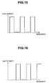
- FIG. 15 is a view showing an example of a spectral distribution of a first illumination light emitted from an illumination section included in the subject observation apparatus according to the second embodiment of the present invention.
- FIG. 16 is a view showing an example of a spectral distribution of a second illumination light emitted from the illumination section included in the subject observation apparatus according to the second embodiment of the present invention.
- FIG. 17 is a view showing an example of a specific configuration of an image pickup section included in the subject observation apparatus according to the second embodiment of the present invention.
- FIG. 14 is a view showing a configuration of a main part of a subject observation apparatus according to the second embodiment of the present invention.
- FIG. 15 is a view showing an example of a spectral distribution of a first illumination light emitted from an illumination section included in the
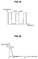
- FIG. 18 is a view showing an example of a specific configuration of an optical modulator included in the image pickup section in FIG 17 .
- FIG. 19 is a view showing an example of light transmission rates of the light selective-transmitting portion and the light-transmitting portion included in the optical modulator in FIG. 18 .
- FIG. 20 is a view showing a modulation result in a case where an optical modulation has been performed by the optical modulator in FIG. 18 on the scattering lights having the scattering angle distributions in FIG. 3 .
- a subject observation apparatus 1001 includes: an illumination section 1002 that emits illumination light to a subject 102A; an image pickup section 1003 that generates an image pickup signal by photoelectrically converting the optically modulated return light of the illumination light, and outputs the generated image pickup signal; a signal processing section 1004 that generates a video signal by signal-processing the image pickup signal and outputs the generated video signal; and a display section 1005 that displays an image of the subject 102A based on the video signal.
- the subject 102A has at least an internal structure in which the above-described first scattering medium 102b and the second scattering medium 102c are arranged in a random manner.
- the illumination section 1002 includes a switch 1002a as a spectral characteristic switching section and is capable of emitting an illumination light while switching between two kinds of illumination lights having spectral distributions different from each other. Specifically, the illumination section 1002 is capable of emitting the illumination light while switching between a first illumination light having a first comb-shaped spectral distribution as shown in FIG. 15 and a second illumination light having a second comb-shaped spectral distribution as shown in FIG. 16 , for example, using the switch 1002a. Note that the wavelength bands in which the light intensity is maximum do not overlap each other in the first comb-shaped spectral distribution and the second comb-shaped distribution.
- the image pickup section 1003 is configured by including: a first optical system 1003a that emits an incident return light as a parallel light having an angle corresponding to an incident angle at which the return light enters the first optical system 1003a itself; an optical modulator 1003b that optically modulates the parallel light emitted from the first optical system 1003a; a second optical system 1003c that forms an image of the light modulated by the optical modulator 3b; and an image pickup device 1003d that generates an image pickup signal by photoelectrically converting the light whose image has been formed by the second optical system 1003c.
- optical modulation section of the present embodiment is configured of the first optical system 1003a and the optical modulator 1003b.
- the first optical system 1003a and the second optical system 1003c are configured of Fresnel lenses having approximately the same diameter.
- the first optical system 1003a as long as it can emit the incident return light as a parallel light, is not limited to one configured of a single Fresnel lens, and may be configured by combining a plurality of lenses.
- the optical modulator 1003b as an optical modulation section is formed in a disk shape having approximately the same diameter as those of the first optical system 1003a and the second optical system 1003c, for example.
- the optical modulator 1003b is formed by including a light selective-transmitting portion 1003b1 and the light-transmitting portion 1003b2 as two regions, the light transmission rates of which are different from each other.
- the light selective-transmitting portion 1003b1 is so formed as to transmit only the lights of wavelength bands coincident with the first comb-shaped spectral distribution and shield the lights of wavelength bands other than the wavelength bands coincident with the first comb-shaped spectral distribution.
- the light-transmitting portion 1003b2 is so formed as to transmit substantially all the incident lights, as shown in FIG. 19 .
- a user operates the switch 1002a to cause the illumination section 1002 to emit the first illumination light.
- the first illumination light emitted from the illumination section 1002 as a light-emitting section is multiply-scattered in the subject 102A, and thereafter incident on the first optical system 1003a as return lights.
- the return lights are incident on the first optical system 1003a as the lights each having the scattering angle equal to or larger than zero degree and smaller than 90 degrees.
- the return lights are from the first scattering medium 102b, the return lights have the scattering angle distribution shown by the curve Db in FIG. 3 .
- the return lights are from the second scattering medium 102c, the return lights have the scattering angle distribution shown by the curve Dc in FIG. 3 .
- the return lights of the first illumination light pass through the first optical system 1003a, and thereafter incident, as parallel lights, on the optical modulator 1003b.
- the light selective-transmitting portion 1003b1 has such a characteristic as to transmit only the lights of the wavelength bands coincident with the first comb-shaped spectral distribution, the parallel lights as the return lights of the first illumination light pass through the optical modulator 1003b.
- the optical modulator 1003b having the above-described configuration transmits the parallel lights corresponding to the return lights of the first illumination light with the intensities thereof substantially maintained, without performing optical modulation on the return lights.
- the parallel lights which have passed through the optical modulator 1003b are image-formed by the second optical system 1003c, and then photoelectrically converted by the image pickup device 1003d to be outputted as an image pickup signal to a signal processing section 1004.
- the image pickup signal outputted from the image pickup device 1003d as a signal output section is converted into a video signal by the signal processing section 1004, and thereafter outputted on the display section 1005.
- the image of the subject 102A having almost natural color is outputted on the display section 1005.
- the user operates the switch 1002a to cause the illumination section 1002 to emit the second illumination light.
- the second illumination light emitted from the illumination section 1002 as a light-emitting section is multiply-scattered in the subject 102A, and thereafter being incident on the first optical system 1003a as return lights.
- the return lights are incident on the first optical system 1003a as the lights each having the scattering angle equal to or larger than zero degree and smaller than 90 degrees.
- the return lights when the return lights are from the first scattering medium 102b, the return lights have the scattering angle distribution shown by the curve Db in FIG. 3 .
- the return lights when the return lights are from the second scattering medium 102c, the return lights have the scattering angle distribution shown by the curve Dc in FIG. 3 .
- the return lights of the second illumination light pass through the first optical system 1003a, and thereafter are incident, as parallel lights, on the optical modulator 1003b.
- the return lights whose incident angles with respect to the first optical system 1003a are equal to or larger than zero degree and equal to or smaller than a predetermined angle ⁇ 2 pass through the light-transmitting portion 1003b2 of the optical modulator 1003b, so that the lights are emitted to the second optical system 1003c with the intensities of the lights being substantially maintained.
- the return lights whose incident angles with respect to the first optical system 1003a are larger than the predetermined angle ⁇ 2 and smaller than 90 degrees are shielded by the light selective-transmitting portion 1003b1 of the optical modulator 1003b.
- the optical modulator 1003b having the above-described configuration optically modulates the parallel lights corresponding to the return lights of the second illumination light so as to emit the lights to the second optical system 1003c with the intensities of the lights substantially maintained when the scattering angles of the return lights are equal to or larger than zero degree and equal to or smaller than a predetermined angle 92, and shield the lights when the scattering angles of the returns lights are larger than the predetermined angle ⁇ 2 and smaller than 90 degrees.
- the scattering angle distributions corresponding to the intensities of the return lights of the second illumination light before and after passing through the first optical system 1003a and the optical modulator 1003b change from the distributions shown by the curves Db and Dc in FIG. 3 to the distributions shown by the curves Dbn and Dcn in FIG. 20 .
- the parallel lights which have been optically modulated by the optical modulator 1003b are image-formed by the second optical system 1003c, photoelectrically converted by the image pickup device 1003d, and thereafter outputted to the signal processing section 1004 as an image pickup signal.
- the image pickup signal outputted from the image pickup device 1003d as a signal output section is converted into a video signal by the signal processing section 1004, and thereafter being outputted on the display section 1005.
- the display section 1005 is displayed the image of the subject 102A having almost natural color in which the light intensity difference between the curve Dbn and the curve Dcn in FIG. 20 is exhibited as a brightness difference.
- the subject 102A is a living tissue
- the first scattering medium 102b is a normal tissue
- the second scattering medium 102c is a tumor tissue.
- the portion where the tumor tissue exists looks brighter than other portions in the image of subject 102A displayed on the display section 1005. That is, when endoscopes and the like provided with the image pickup section 1003 having the above-described configuration are used, it is possible to easily identify the region where the tumor tissue which shows little characteristic finding.
- the switching between whether or not to perform optical modulation in the optical modulator 1003b can be performed only by switching the kinds of the illumination lights emitted from the illumination section 1002, without changing the characteristic of the optical modulator 1003b itself.
- the subject observation apparatus 1001 of the present embodiment can identify the region exhibiting a desired scattering characteristic in the scattering medium which has a plurality of regions each having a different scattering characteristic, with a simple operation.
- the color of the image of the subject 102A may be changed when the optical modulation is performed in the optical modulator 1003b.
- the number of the wavelength bands (the number of the comb teeth in the second comb-shaped spectral distribution) in which the light intensity becomes maximum is increased or decreased in accordance with the characteristic of the light selective-transmitting portion 1003b1, or the maximum value of the light intensity (the height of the comb teeth in the second comb-shaped spectral distribution) is made smaller than that in the first comb-shaped spectral distribution as shown in FIG. 15 .
- the illumination section 1002 in the subject observation apparatus 1001 of the present embodiment is not limited to the illumination section which emits an illumination light while switching between the first illumination light without the optical modulation in the optical modulator 1003b and the second illumination light with the optical modulation in the optical modulator.
- the illumination section 1002 may be configured to be able to gradually change the spectral distribution of the illumination light emitted by the illumination section itself, from the first comb-shaped spectral distribution to the second comb-shaped spectral distribution (and vice versa).
- Such a configuration makes it possible for the optical modulator 1003b to continuously or gradually perform the optical modulation on the light emitted from the first optical system 1003a.
- the switching of the illumination lights emitted from the illumination section 1002 is not limited to the switching performed through the switch 1002a.
- the switching may be performed in conjunction with operation of the magnification lever or the rigidity change lever in the endoscope.
Applications Claiming Priority (2)
| Application Number | Priority Date | Filing Date | Title |
|---|---|---|---|
| JP2008190175A JP5191831B2 (ja) | 2008-07-23 | 2008-07-23 | 被検体観測装置及び被検体観測装置の作動方法 |
| JP2008190176A JP2010025867A (ja) | 2008-07-23 | 2008-07-23 | 被検体観測装置及び被検体観測方法 |
Publications (2)
| Publication Number | Publication Date |
|---|---|
| EP2147635A1 true EP2147635A1 (de) | 2010-01-27 |
| EP2147635B1 EP2147635B1 (de) | 2016-04-20 |
Family
ID=41066528
Family Applications (1)
| Application Number | Title | Priority Date | Filing Date |
|---|---|---|---|
| EP09008979.8A Not-in-force EP2147635B1 (de) | 2008-07-23 | 2009-07-09 | Vorrichtung und Verfahren für die Beobachtung eines Gegenstandes |
Country Status (3)
| Country | Link |
|---|---|
| US (1) | US9345385B2 (de) |
| EP (1) | EP2147635B1 (de) |
| KR (1) | KR101109968B1 (de) |
Families Citing this family (4)
| Publication number | Priority date | Publication date | Assignee | Title |
|---|---|---|---|---|
| US8780362B2 (en) | 2011-05-19 | 2014-07-15 | Covidien Lp | Methods utilizing triangulation in metrology systems for in-situ surgical applications |
| WO2013188014A1 (en) * | 2012-06-13 | 2013-12-19 | Boston Scientific Scimed, Inc. | Medical device visualization system |
| US10586198B2 (en) | 2016-06-17 | 2020-03-10 | Predictive Safety Srp, Inc. | Cognitive testing system and method |
| US11835707B2 (en) * | 2017-05-04 | 2023-12-05 | Massachusetts Institute Of Technology | Scanning optical imaging device |
Citations (8)
| Publication number | Priority date | Publication date | Assignee | Title |
|---|---|---|---|---|
| US5028135A (en) * | 1989-09-05 | 1991-07-02 | University Of Akron | Combined high spatial resolution and high total intensity selection optical train for laser spectroscopy |
| US5305073A (en) * | 1992-02-12 | 1994-04-19 | Precision Detectors, Inc. | Methods and apparatus for molecular characterization |
| JPH11258167A (ja) | 1998-03-09 | 1999-09-24 | Asahi Techno Glass Corp | ガラス管の欠陥検査方法および装置 |
| US6420709B1 (en) * | 1992-07-15 | 2002-07-16 | Optix Lp | Methods of minimizing scattering and improving tissue sampling in non-invasive testing and imaging |
| US6690520B1 (en) | 1996-05-15 | 2004-02-10 | Sysmex Corporation | Optical system for visualizing an object in a light scattering medium |
| JP2006341078A (ja) | 2005-05-12 | 2006-12-21 | Olympus Medical Systems Corp | 生体観測装置 |
| EP1787577A1 (de) * | 2004-08-30 | 2007-05-23 | Olympus Corporation | Endoskop |
| JP2007325781A (ja) * | 2006-06-08 | 2007-12-20 | Olympus Medical Systems Corp | 散乱媒質内観察装置および散乱媒質内観察方法 |
Family Cites Families (19)
| Publication number | Priority date | Publication date | Assignee | Title |
|---|---|---|---|---|
| JPS61169819A (ja) * | 1985-01-23 | 1986-07-31 | Canon Inc | 光変調装置 |
| JPS6244650A (ja) | 1985-08-22 | 1987-02-26 | Canon Inc | 粒子解析装置 |
| JPH0313847A (ja) | 1989-06-12 | 1991-01-22 | Toa Medical Electronics Co Ltd | 光学式粒子分析装置 |
| JP3260469B2 (ja) | 1992-04-01 | 2002-02-25 | シスメックス株式会社 | 粒子分析装置 |
| JPH10221248A (ja) | 1997-02-06 | 1998-08-21 | Nikon Corp | 光学的検査方法及び光学的検査装置 |
| JPH10246697A (ja) | 1997-03-03 | 1998-09-14 | Nikon Corp | 光学的検査方法及び光学的検査装置 |
| US6091984A (en) | 1997-10-10 | 2000-07-18 | Massachusetts Institute Of Technology | Measuring tissue morphology |
| JP3635901B2 (ja) | 1997-12-10 | 2005-04-06 | 富士電機システムズ株式会社 | 前方散乱光受光光学系及びその製造方法 |
| WO2000043750A2 (en) | 1999-01-25 | 2000-07-27 | Newton Laboratories, Inc. | Imaging of tissue using polarized light |
| JP2000230901A (ja) | 1999-02-09 | 2000-08-22 | Mitsubishi Chemicals Corp | 光学ユニット |
| US7253897B2 (en) * | 2001-06-01 | 2007-08-07 | Cidra Corporation | Optical spectrum analyzer |
| JP4535697B2 (ja) | 2003-07-23 | 2010-09-01 | オリンパス株式会社 | 生体組織の光散乱観測内視鏡装置 |
| EP1709405A1 (de) * | 2003-09-26 | 2006-10-11 | Tidal Photonics, Inc. | Vorrichtungen und verfahren in bezug auf verbesserte spektrale messsysteme |
| GB0513128D0 (en) * | 2005-06-27 | 2005-08-03 | Ojk Consulting Ltd | An optical arrangement for a flow cytometer |
| US7336323B2 (en) * | 2005-09-27 | 2008-02-26 | Chemimage Corporation | Liquid crystal filter with tunable rejection band |
| AU2006302086B2 (en) * | 2005-10-11 | 2011-08-18 | Duke University | Systems and method for endoscopic angle-resolved low coherence interferometry |
| WO2007133684A2 (en) | 2006-05-12 | 2007-11-22 | Northwestern University | Systems, methods, and apparatuses of low-coherence enhanced backscattering spectroscopy |
| US7460248B2 (en) * | 2006-05-15 | 2008-12-02 | Carestream Health, Inc. | Tissue imaging system |
| AU2007275720A1 (en) | 2006-07-18 | 2008-01-24 | Boston Medical Center Corporation | Device with integrated multi-fiber optical probe and methods of use |
-
2009
- 2009-05-26 KR KR1020090045876A patent/KR101109968B1/ko not_active IP Right Cessation
- 2009-07-09 EP EP09008979.8A patent/EP2147635B1/de not_active Not-in-force
- 2009-07-20 US US12/505,751 patent/US9345385B2/en active Active
Patent Citations (8)
| Publication number | Priority date | Publication date | Assignee | Title |
|---|---|---|---|---|
| US5028135A (en) * | 1989-09-05 | 1991-07-02 | University Of Akron | Combined high spatial resolution and high total intensity selection optical train for laser spectroscopy |
| US5305073A (en) * | 1992-02-12 | 1994-04-19 | Precision Detectors, Inc. | Methods and apparatus for molecular characterization |
| US6420709B1 (en) * | 1992-07-15 | 2002-07-16 | Optix Lp | Methods of minimizing scattering and improving tissue sampling in non-invasive testing and imaging |
| US6690520B1 (en) | 1996-05-15 | 2004-02-10 | Sysmex Corporation | Optical system for visualizing an object in a light scattering medium |
| JPH11258167A (ja) | 1998-03-09 | 1999-09-24 | Asahi Techno Glass Corp | ガラス管の欠陥検査方法および装置 |
| EP1787577A1 (de) * | 2004-08-30 | 2007-05-23 | Olympus Corporation | Endoskop |
| JP2006341078A (ja) | 2005-05-12 | 2006-12-21 | Olympus Medical Systems Corp | 生体観測装置 |
| JP2007325781A (ja) * | 2006-06-08 | 2007-12-20 | Olympus Medical Systems Corp | 散乱媒質内観察装置および散乱媒質内観察方法 |
Non-Patent Citations (1)
| Title |
|---|
| ANDERSON G E ET AL: "MICROSCOPE IMAGING THROUGH HIGHLY SCATTERING MEDIA", OPTICS LETTERS, OSA, OPTICAL SOCIETY OF AMERICA, WASHINGTON, DC, US, vol. 19, no. 13, 1 July 1994 (1994-07-01), pages 981 - 983, XP000454703, ISSN: 0146-9592 * |
Also Published As
| Publication number | Publication date |
|---|---|
| EP2147635B1 (de) | 2016-04-20 |
| KR20100010899A (ko) | 2010-02-02 |
| KR101109968B1 (ko) | 2012-02-17 |
| US20100022858A1 (en) | 2010-01-28 |
| US9345385B2 (en) | 2016-05-24 |
Similar Documents
| Publication | Publication Date | Title |
|---|---|---|
| US10111614B2 (en) | Apparatus and method for detecting NIR fluorescence at sentinel lymph node | |
| JP6062405B2 (ja) | 赤外蛍光を観察するための手術用顕微鏡、顕微鏡検査方法、および手術用顕微鏡の使用 | |
| JP5133595B2 (ja) | 照明光検出用光学系並びにそれを備えた光学装置及び内視鏡装置 | |
| US7746560B2 (en) | Illumination optical system that uses a solid-state lighting element which generates white light, and an optical device equipped therewith | |
| EP2446809B1 (de) | Elektronisches Endoskopsystem mit Prozessorvorrichtung und Verfahren zur Verarbeitung endoskopischer Bilder | |
| US8007433B2 (en) | Electronic endoscope | |
| NL2009124C2 (en) | Method and device for detecting fluorescence radiation. | |
| WO2009081969A1 (ja) | 生体画像取得装置 | |
| US20140037179A1 (en) | Fluoroscopy apparatus and fluoroscopy system | |
| US10527861B2 (en) | Color separation prism and imaging device | |
| WO2022257946A1 (zh) | 多光谱成像系统、成像方法和存储介质 | |
| JP6120722B2 (ja) | 観察装置及び観察装置の作動方法 | |
| EP2147635B1 (de) | Vorrichtung und Verfahren für die Beobachtung eines Gegenstandes | |
| EP3263007A1 (de) | Endoskopsystem | |
| EP1935326B1 (de) | Biodiagnostisches gerät | |
| US20220104693A1 (en) | Optical Filter System for a Video Endoscope, Display System and Video Endoscope | |
| US9568721B2 (en) | Fluorescent biological sample operating and monitoring system | |
| JP6617774B2 (ja) | 顕微鏡装置 | |
| JP5191831B2 (ja) | 被検体観測装置及び被検体観測装置の作動方法 | |
| TW201827914A (zh) | 觀察裝置及觀察方法 | |
| JP2010025867A (ja) | 被検体観測装置及び被検体観測方法 | |
| US11415505B2 (en) | Method and system for observing a sample under ambient lighting | |
| US20230172444A1 (en) | Optical Filter for an Objective System of an Endoscope, Objective System, and Endoscope | |
| US20220091039A1 (en) | Filter set, fluorescence observation system and method for simultaneously observing fluorescent and non-fluorescent regions of an object | |
| KR20200070926A (ko) | 복수의 광원 조합을 기반으로 다중 영상을 획득하는 내시경용 촬상 모듈 및 의료용 내시경 |
Legal Events
| Date | Code | Title | Description |
|---|---|---|---|
| PUAI | Public reference made under article 153(3) epc to a published international application that has entered the european phase |
Free format text: ORIGINAL CODE: 0009012 |
|
| 17P | Request for examination filed |
Effective date: 20090709 |
|
| AK | Designated contracting states |
Kind code of ref document: A1 Designated state(s): AT BE BG CH CY CZ DE DK EE ES FI FR GB GR HR HU IE IS IT LI LT LU LV MC MK MT NL NO PL PT RO SE SI SK SM TR |
|
| AX | Request for extension of the european patent |
Extension state: AL BA RS |
|
| 17Q | First examination report despatched |
Effective date: 20100824 |
|
| RAP1 | Party data changed (applicant data changed or rights of an application transferred) |
Owner name: OLYMPUS CORPORATION |
|
| GRAP | Despatch of communication of intention to grant a patent |
Free format text: ORIGINAL CODE: EPIDOSNIGR1 |
|
| INTG | Intention to grant announced |
Effective date: 20151127 |
|
| GRAS | Grant fee paid |
Free format text: ORIGINAL CODE: EPIDOSNIGR3 |
|
| GRAA | (expected) grant |
Free format text: ORIGINAL CODE: 0009210 |
|
| AK | Designated contracting states |
Kind code of ref document: B1 Designated state(s): AT BE BG CH CY CZ DE DK EE ES FI FR GB GR HR HU IE IS IT LI LT LU LV MC MK MT NL NO PL PT RO SE SI SK SM TR |
|
| REG | Reference to a national code |
Ref country code: GB Ref legal event code: FG4D |
|
| REG | Reference to a national code |
Ref country code: CH Ref legal event code: EP |
|
| REG | Reference to a national code |
Ref country code: AT Ref legal event code: REF Ref document number: 791439 Country of ref document: AT Kind code of ref document: T Effective date: 20160515 |
|
| REG | Reference to a national code |
Ref country code: IE Ref legal event code: FG4D |
|
| REG | Reference to a national code |
Ref country code: DE Ref legal event code: R096 Ref document number: 602009037896 Country of ref document: DE |
|
| RAP2 | Party data changed (patent owner data changed or rights of a patent transferred) |
Owner name: OLYMPUS CORPORATION |
|
| REG | Reference to a national code |
Ref country code: LT Ref legal event code: MG4D |
|
| REG | Reference to a national code |
Ref country code: AT Ref legal event code: MK05 Ref document number: 791439 Country of ref document: AT Kind code of ref document: T Effective date: 20160420 |
|
| RAP2 | Party data changed (patent owner data changed or rights of a patent transferred) |
Owner name: OLYMPUS CORPORATION |
|
| REG | Reference to a national code |
Ref country code: NL Ref legal event code: MP Effective date: 20160420 |
|
| RAP2 | Party data changed (patent owner data changed or rights of a patent transferred) |
Owner name: OLYMPUS CORPORATION |
|
| PG25 | Lapsed in a contracting state [announced via postgrant information from national office to epo] |
Ref country code: LT Free format text: LAPSE BECAUSE OF FAILURE TO SUBMIT A TRANSLATION OF THE DESCRIPTION OR TO PAY THE FEE WITHIN THE PRESCRIBED TIME-LIMIT Effective date: 20160420 Ref country code: NL Free format text: LAPSE BECAUSE OF FAILURE TO SUBMIT A TRANSLATION OF THE DESCRIPTION OR TO PAY THE FEE WITHIN THE PRESCRIBED TIME-LIMIT Effective date: 20160420 Ref country code: PL Free format text: LAPSE BECAUSE OF FAILURE TO SUBMIT A TRANSLATION OF THE DESCRIPTION OR TO PAY THE FEE WITHIN THE PRESCRIBED TIME-LIMIT Effective date: 20160420 Ref country code: NO Free format text: LAPSE BECAUSE OF FAILURE TO SUBMIT A TRANSLATION OF THE DESCRIPTION OR TO PAY THE FEE WITHIN THE PRESCRIBED TIME-LIMIT Effective date: 20160720 Ref country code: FI Free format text: LAPSE BECAUSE OF FAILURE TO SUBMIT A TRANSLATION OF THE DESCRIPTION OR TO PAY THE FEE WITHIN THE PRESCRIBED TIME-LIMIT Effective date: 20160420 |
|
| PG25 | Lapsed in a contracting state [announced via postgrant information from national office to epo] |
Ref country code: LV Free format text: LAPSE BECAUSE OF FAILURE TO SUBMIT A TRANSLATION OF THE DESCRIPTION OR TO PAY THE FEE WITHIN THE PRESCRIBED TIME-LIMIT Effective date: 20160420 Ref country code: SE Free format text: LAPSE BECAUSE OF FAILURE TO SUBMIT A TRANSLATION OF THE DESCRIPTION OR TO PAY THE FEE WITHIN THE PRESCRIBED TIME-LIMIT Effective date: 20160420 Ref country code: ES Free format text: LAPSE BECAUSE OF FAILURE TO SUBMIT A TRANSLATION OF THE DESCRIPTION OR TO PAY THE FEE WITHIN THE PRESCRIBED TIME-LIMIT Effective date: 20160420 Ref country code: AT Free format text: LAPSE BECAUSE OF FAILURE TO SUBMIT A TRANSLATION OF THE DESCRIPTION OR TO PAY THE FEE WITHIN THE PRESCRIBED TIME-LIMIT Effective date: 20160420 Ref country code: HR Free format text: LAPSE BECAUSE OF FAILURE TO SUBMIT A TRANSLATION OF THE DESCRIPTION OR TO PAY THE FEE WITHIN THE PRESCRIBED TIME-LIMIT Effective date: 20160420 Ref country code: GR Free format text: LAPSE BECAUSE OF FAILURE TO SUBMIT A TRANSLATION OF THE DESCRIPTION OR TO PAY THE FEE WITHIN THE PRESCRIBED TIME-LIMIT Effective date: 20160721 Ref country code: PT Free format text: LAPSE BECAUSE OF FAILURE TO SUBMIT A TRANSLATION OF THE DESCRIPTION OR TO PAY THE FEE WITHIN THE PRESCRIBED TIME-LIMIT Effective date: 20160822 |
|
| PG25 | Lapsed in a contracting state [announced via postgrant information from national office to epo] |
Ref country code: IT Free format text: LAPSE BECAUSE OF FAILURE TO SUBMIT A TRANSLATION OF THE DESCRIPTION OR TO PAY THE FEE WITHIN THE PRESCRIBED TIME-LIMIT Effective date: 20160420 Ref country code: BE Free format text: LAPSE BECAUSE OF FAILURE TO SUBMIT A TRANSLATION OF THE DESCRIPTION OR TO PAY THE FEE WITHIN THE PRESCRIBED TIME-LIMIT Effective date: 20160420 |
|
| REG | Reference to a national code |
Ref country code: DE Ref legal event code: R097 Ref document number: 602009037896 Country of ref document: DE |
|
| PG25 | Lapsed in a contracting state [announced via postgrant information from national office to epo] |
Ref country code: SK Free format text: LAPSE BECAUSE OF FAILURE TO SUBMIT A TRANSLATION OF THE DESCRIPTION OR TO PAY THE FEE WITHIN THE PRESCRIBED TIME-LIMIT Effective date: 20160420 Ref country code: RO Free format text: LAPSE BECAUSE OF FAILURE TO SUBMIT A TRANSLATION OF THE DESCRIPTION OR TO PAY THE FEE WITHIN THE PRESCRIBED TIME-LIMIT Effective date: 20160420 Ref country code: EE Free format text: LAPSE BECAUSE OF FAILURE TO SUBMIT A TRANSLATION OF THE DESCRIPTION OR TO PAY THE FEE WITHIN THE PRESCRIBED TIME-LIMIT Effective date: 20160420 Ref country code: DK Free format text: LAPSE BECAUSE OF FAILURE TO SUBMIT A TRANSLATION OF THE DESCRIPTION OR TO PAY THE FEE WITHIN THE PRESCRIBED TIME-LIMIT Effective date: 20160420 Ref country code: CZ Free format text: LAPSE BECAUSE OF FAILURE TO SUBMIT A TRANSLATION OF THE DESCRIPTION OR TO PAY THE FEE WITHIN THE PRESCRIBED TIME-LIMIT Effective date: 20160420 |
|
| PLBE | No opposition filed within time limit |
Free format text: ORIGINAL CODE: 0009261 |
|
| STAA | Information on the status of an ep patent application or granted ep patent |
Free format text: STATUS: NO OPPOSITION FILED WITHIN TIME LIMIT |
|
| PG25 | Lapsed in a contracting state [announced via postgrant information from national office to epo] |
Ref country code: SM Free format text: LAPSE BECAUSE OF FAILURE TO SUBMIT A TRANSLATION OF THE DESCRIPTION OR TO PAY THE FEE WITHIN THE PRESCRIBED TIME-LIMIT Effective date: 20160420 |
|
| REG | Reference to a national code |
Ref country code: CH Ref legal event code: PL |
|
| GBPC | Gb: european patent ceased through non-payment of renewal fee |
Effective date: 20160720 |
|
| 26N | No opposition filed |
Effective date: 20170123 |
|
| PG25 | Lapsed in a contracting state [announced via postgrant information from national office to epo] |
Ref country code: MC Free format text: LAPSE BECAUSE OF FAILURE TO SUBMIT A TRANSLATION OF THE DESCRIPTION OR TO PAY THE FEE WITHIN THE PRESCRIBED TIME-LIMIT Effective date: 20160420 |
|
| PG25 | Lapsed in a contracting state [announced via postgrant information from national office to epo] |
Ref country code: LI Free format text: LAPSE BECAUSE OF NON-PAYMENT OF DUE FEES Effective date: 20160731 Ref country code: FR Free format text: LAPSE BECAUSE OF NON-PAYMENT OF DUE FEES Effective date: 20160801 Ref country code: CH Free format text: LAPSE BECAUSE OF NON-PAYMENT OF DUE FEES Effective date: 20160731 |
|
| REG | Reference to a national code |
Ref country code: FR Ref legal event code: ST Effective date: 20170331 |
|
| REG | Reference to a national code |
Ref country code: IE Ref legal event code: MM4A |
|
| PG25 | Lapsed in a contracting state [announced via postgrant information from national office to epo] |
Ref country code: SI Free format text: LAPSE BECAUSE OF FAILURE TO SUBMIT A TRANSLATION OF THE DESCRIPTION OR TO PAY THE FEE WITHIN THE PRESCRIBED TIME-LIMIT Effective date: 20160420 Ref country code: GB Free format text: LAPSE BECAUSE OF NON-PAYMENT OF DUE FEES Effective date: 20160720 |
|
| PG25 | Lapsed in a contracting state [announced via postgrant information from national office to epo] |
Ref country code: IE Free format text: LAPSE BECAUSE OF NON-PAYMENT OF DUE FEES Effective date: 20160709 |
|
| PG25 | Lapsed in a contracting state [announced via postgrant information from national office to epo] |
Ref country code: LU Free format text: LAPSE BECAUSE OF NON-PAYMENT OF DUE FEES Effective date: 20160709 |
|
| PG25 | Lapsed in a contracting state [announced via postgrant information from national office to epo] |
Ref country code: CY Free format text: LAPSE BECAUSE OF FAILURE TO SUBMIT A TRANSLATION OF THE DESCRIPTION OR TO PAY THE FEE WITHIN THE PRESCRIBED TIME-LIMIT Effective date: 20160420 Ref country code: HU Free format text: LAPSE BECAUSE OF FAILURE TO SUBMIT A TRANSLATION OF THE DESCRIPTION OR TO PAY THE FEE WITHIN THE PRESCRIBED TIME-LIMIT; INVALID AB INITIO Effective date: 20090709 |
|
| PG25 | Lapsed in a contracting state [announced via postgrant information from national office to epo] |
Ref country code: MK Free format text: LAPSE BECAUSE OF FAILURE TO SUBMIT A TRANSLATION OF THE DESCRIPTION OR TO PAY THE FEE WITHIN THE PRESCRIBED TIME-LIMIT Effective date: 20160420 Ref country code: TR Free format text: LAPSE BECAUSE OF FAILURE TO SUBMIT A TRANSLATION OF THE DESCRIPTION OR TO PAY THE FEE WITHIN THE PRESCRIBED TIME-LIMIT Effective date: 20160420 Ref country code: IS Free format text: LAPSE BECAUSE OF FAILURE TO SUBMIT A TRANSLATION OF THE DESCRIPTION OR TO PAY THE FEE WITHIN THE PRESCRIBED TIME-LIMIT Effective date: 20160420 Ref country code: MT Free format text: LAPSE BECAUSE OF NON-PAYMENT OF DUE FEES Effective date: 20160731 |
|
| PG25 | Lapsed in a contracting state [announced via postgrant information from national office to epo] |
Ref country code: BG Free format text: LAPSE BECAUSE OF FAILURE TO SUBMIT A TRANSLATION OF THE DESCRIPTION OR TO PAY THE FEE WITHIN THE PRESCRIBED TIME-LIMIT Effective date: 20160420 |
|
| PGFP | Annual fee paid to national office [announced via postgrant information from national office to epo] |
Ref country code: DE Payment date: 20180626 Year of fee payment: 10 |
|
| REG | Reference to a national code |
Ref country code: DE Ref legal event code: R119 Ref document number: 602009037896 Country of ref document: DE |
|
| PG25 | Lapsed in a contracting state [announced via postgrant information from national office to epo] |
Ref country code: DE Free format text: LAPSE BECAUSE OF NON-PAYMENT OF DUE FEES Effective date: 20200201 |