EP2147170B1 - Seismisches strukturelement - Google Patents
Seismisches strukturelement Download PDFInfo
- Publication number
- EP2147170B1 EP2147170B1 EP08747677.6A EP08747677A EP2147170B1 EP 2147170 B1 EP2147170 B1 EP 2147170B1 EP 08747677 A EP08747677 A EP 08747677A EP 2147170 B1 EP2147170 B1 EP 2147170B1
- Authority
- EP
- European Patent Office
- Prior art keywords
- connection
- plate
- joint
- diagonal
- plates
- Prior art date
- Legal status (The legal status is an assumption and is not a legal conclusion. Google has not performed a legal analysis and makes no representation as to the accuracy of the status listed.)
- Active
Links
Images


Classifications
-
- E—FIXED CONSTRUCTIONS
- E04—BUILDING
- E04H—BUILDINGS OR LIKE STRUCTURES FOR PARTICULAR PURPOSES; SWIMMING OR SPLASH BATHS OR POOLS; MASTS; FENCING; TENTS OR CANOPIES, IN GENERAL
- E04H9/00—Buildings, groups of buildings or shelters adapted to withstand or provide protection against abnormal external influences, e.g. war-like action, earthquake or extreme climate
- E04H9/02—Buildings, groups of buildings or shelters adapted to withstand or provide protection against abnormal external influences, e.g. war-like action, earthquake or extreme climate withstanding earthquake or sinking of ground
- E04H9/021—Bearing, supporting or connecting constructions specially adapted for such buildings
- E04H9/0237—Structural braces with damping devices
-
- E—FIXED CONSTRUCTIONS
- E04—BUILDING
- E04B—GENERAL BUILDING CONSTRUCTIONS; WALLS, e.g. PARTITIONS; ROOFS; FLOORS; CEILINGS; INSULATION OR OTHER PROTECTION OF BUILDINGS
- E04B1/00—Constructions in general; Structures which are not restricted either to walls, e.g. partitions, or floors or ceilings or roofs
- E04B1/18—Structures comprising elongated load-supporting parts, e.g. columns, girders, skeletons
- E04B1/24—Structures comprising elongated load-supporting parts, e.g. columns, girders, skeletons the supporting parts consisting of metal
- E04B1/2403—Connection details of the elongated load-supporting parts
- E04B2001/2439—Adjustable connections, e.g. using elongated slots or threaded adjustment elements
-
- E—FIXED CONSTRUCTIONS
- E04—BUILDING
- E04B—GENERAL BUILDING CONSTRUCTIONS; WALLS, e.g. PARTITIONS; ROOFS; FLOORS; CEILINGS; INSULATION OR OTHER PROTECTION OF BUILDINGS
- E04B1/00—Constructions in general; Structures which are not restricted either to walls, e.g. partitions, or floors or ceilings or roofs
- E04B1/18—Structures comprising elongated load-supporting parts, e.g. columns, girders, skeletons
- E04B1/24—Structures comprising elongated load-supporting parts, e.g. columns, girders, skeletons the supporting parts consisting of metal
- E04B1/2403—Connection details of the elongated load-supporting parts
- E04B2001/2442—Connections with built-in weakness points
-
- E—FIXED CONSTRUCTIONS
- E04—BUILDING
- E04H—BUILDINGS OR LIKE STRUCTURES FOR PARTICULAR PURPOSES; SWIMMING OR SPLASH BATHS OR POOLS; MASTS; FENCING; TENTS OR CANOPIES, IN GENERAL
- E04H9/00—Buildings, groups of buildings or shelters adapted to withstand or provide protection against abnormal external influences, e.g. war-like action, earthquake or extreme climate
- E04H9/02—Buildings, groups of buildings or shelters adapted to withstand or provide protection against abnormal external influences, e.g. war-like action, earthquake or extreme climate withstanding earthquake or sinking of ground
- E04H9/028—Earthquake withstanding shelters
-
- Y—GENERAL TAGGING OF NEW TECHNOLOGICAL DEVELOPMENTS; GENERAL TAGGING OF CROSS-SECTIONAL TECHNOLOGIES SPANNING OVER SEVERAL SECTIONS OF THE IPC; TECHNICAL SUBJECTS COVERED BY FORMER USPC CROSS-REFERENCE ART COLLECTIONS [XRACs] AND DIGESTS
- Y10—TECHNICAL SUBJECTS COVERED BY FORMER USPC
- Y10T—TECHNICAL SUBJECTS COVERED BY FORMER US CLASSIFICATION
- Y10T403/00—Joints and connections
- Y10T403/16—Joints and connections with adjunctive protector, broken parts retainer, repair, assembly or disassembly feature
- Y10T403/1616—Position or guide means
- Y10T403/1624—Related to joint component
Definitions
- the present invention generally relates to a link beam joint that is utilized in a structure that is subject to seismic loads.
- the link beam joint is a link-fuse joint that lengthens dynamic periods and reduces the forces that must be resisted within shear wall or frame construction of structures so that the walls or frames can withstand seismic activity without sustaining significant damage.
- Structures have been constructed, and are being constructed daily, in areas subject to seismic activity. Special considerations must be given to the design of such structures.
- the walls and frames of these structures must be designed not only to accommodate normal loading conditions, but also those loading conditions that are unique to seismic activity. For example, link beams within shear walls are typically subject to cyclic motions during seismic events. To withstand such loading conditions, structures subject to seismic activity must behave with ductility to allow for the dissipation of energy under those extreme loads.
- reinforced link beams subject to seismic loads have been designed with the beams fully connected directly to reinforced concrete shear walls with fully developed reinforcing bars. These beams are designed to elastically resist service wind and frequent earthquake events and are designed to plastically perform or hinge during severe earthquake events.
- link beam length-to-depth ratios are relatively small, shear will typically control the behavior of the beams.
- diagonal reinforcement arranged in elevation in the shape of an "X" is apically required.
- embedded structural steel members are placed within the reinforced concrete beams to resist the load.
- these beams are designed to permanently deform in a severe seismic event. Reinforcing bars and structural steel, if used permanently, deform and concrete cracks or spalls. Energy is dissipated and beams act with ductility but plastically deform with conventional designs.
- steel beams located between braces are designed to fuse during extreme seismic events. The behavior is similar to beam links used in eccentrically braced frames. These beams are designed to yield and plastically deform, protecting the bracing members and columns and the overall integrity of the structure.
- U.S. Patent Application Publication 2005/284041 A1 describes a seismic-protection wheel locational anchorage including a first fastening member and a second fastening member.
- the first fastening member has a first horizontal part and a first perpendicular part vertically and downwardly extending from one end of the first horizontal part.
- the second fastening member has a second perpendicular part and a second horizontal part extending parallel from a lower end of the second perpendicular part.
- the first horizontal part of the first fastening member is fastened to the bottom of a machine frame.
- the second horizontal part is securely fastened to the ground.
- a "link-fuse" joint consistent with the present invention enables a shear wall or steel braced frame to withstand a seismic event without experiencing significant beam or joint failure.
- the link-fuse joint is also referred to as a joint connection herein.
- the link-fuse joint is generally utilized in a link beam assembly.
- the link-fuse joint may be incorporated, for example, into the reinforced concrete shear walls or steel braced frames of a building or other structure subject to seismic activity and improves the structure's dynamic characteristics by allowing the link-fuse joint to slip under extreme loads. This slippage changes the structure's dynamic characteristics by lengthening the structure's fundamental period and softening the structure, which allows the structure to exhibit elastic properties during seismic events.
- link-fuse joint By utilizing the link-fuse joint, it is generally not necessary to use shear walls or steel frames and link beams as large as typically used for a similar sized structure to withstand an extreme seismic event. Accordingly, overall building costs can also be reduced through the use of a link-fuse joint consistent with the present invention.
- the link-fuse joint may be employed in a link beam, where the beam attaches to neighboring walls or frames of a structure.
- a plate assembly within a beam is designed to mate and be held together by a pin assembly extending through connection plates that extend outward from the plate assembly. Additionally, the plate assembly has diagonally opposed slots.
- the plate assembly may be secured together, for example, by a threaded rod, multiple threaded rods, multiple high-strength steel bolts, and the like. These connections allow for the slotted plates to slip relative to each other when subject to extreme seismic loads without a significant loss in clamping force. Movement in the joint may be further restricted by treating the faying surfaces of the plate assembly with brass.
- the brass shims used within the connection possess a predetermined load-displacement behavior and excellent cyclic attributes.
- the friction developed from the clamping force within the plate assembly with the brass shims against the steel surface prevents the joint from slipping under most service loading conditions, such as those imposed by wind, gravity, and moderate seismic vents.
- the threaded rod(s) or high-strength bolts are torqued to provide a slip resistant connection by developing friction between the connected surfaces.
- the level of force applied to the connection exceeds the product of the coefficient of friction times the normal rod or bolt clamping force, which causes the joint to slip in a planer direction while maintaining connectivity.
- the sliding of the joint during seismic events provides for the transfer of shear forces and bending moment from the link beams to the shear walls or braced frames. This sliding dissipates energy, which is also known as “fusing. " This energy dissipation reduces potential damage to the structure due to seismic activity.
- a joint connection that accommodates relative lateral and vertical movement between connected walls during seismic activity, the joint connection is provided.
- the joint connection comprises a first plate assembly having (a) two or more parallel first connection plates each including a first diagonal slot formed therethrough that extends along a first diagonal direction, and (b) a first securable plate to which the first connection plates are immovably fixed.
- the first diagonal slots are aligned with each other.
- the first securable plate being secured to a first support member that is a part of or connected to a first wall.
- the two or more first connection plates extend along a lateral direction from the first securable plate and in parallel first planes, wherein the first diagonal slot is diagonal relative to a vertical direction which is orthogonal to the lateral direction.
- the joint connection further comprises a second plate assembly having (a) at least one second connection plate the at least one second connection plate positioned between two of the first connection plates and including a second diagonal slot formed therethrough that extends along a second diagonal direction, and (b) a second securable plate to which the at least one second connection plate is immovably secured.
- the second securable plate is secured to a second support member that is a part of or connected to a second wall.
- Each second connection plate extends along the lateral direction in a respective second plane that is parallel to the first planes.
- the second diagonal slot is diagonally opposite to the first diagonal slot relative to the vertical direction such that the first diagonal direction and the second diagonal direction cross each other
- Each second connection plate is positioned such that at least a portion of its second diagonal slot aligns with each other second diagonal slot and overlaps a portion of each first diagonal slot.
- the joint connection further comprises a pin assembly clamping together the first plate assembly and the second plate assembly with a clamping force and including a pin extending through each first diagonal slot and each second diagonal slot.
- the joint connection permits lateral slippage along the lateral direction, vertical slippage along the vertical direction, or both, of the first plate assembly and the second plate assembly relative to each other when the joint connection is subject to a seismic load but without significant loss of the clamping force.
- a joint connection consistent with the present invention will slip under extreme seismic loads to dissipate the energy, the joints will, however, remain elastic due to their construction. Furthermore, the joint generally does not become plastic nor yields when subjected to the loading and the slip. This allows, for example, a shear wall structure utilizing the joint connection to remain in service after enduring a seismic event and resist further seismic activity.
- the link-fuse joint enables a shear wall or steel braced frame to withstand a seismic event without experiencing significant beam or joint failure.
- the link-fuse joint may be incorporated, for example, into the reinforced concrete shear walls or steel braced frames of a building or other structure subject to seismic activity and improves the structure's dynamic characteristics by allowing the link-fuse joint to slip under extreme loads. This slippage changes the structure's dynamic characteristics by lengthening the structure's fundamental period and softening the structure, which allows the structure to exhibit elastic properties during seismic events.
- it is generally not necessary to use shear walls or steel frames and link beams as large as typically used for a similar sized structure to withstand an extreme seismic event. Accordingly, overall building costs can also be reduced through the use of a link-fuse joint consistent with the present invention.
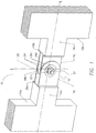
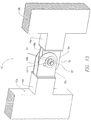
- FIG. 1 is a perspective view of one embodiment of a link beam joint assembly 10 consistent with the present invention.
- a link-fuse joint 19 in structures comprising other materials, such as structural steel and/or composite materials, e. g., a combination of structural steel and reinforced concrete.
- the link-fuse joint may be used between columns within a braced frame, for example.
- the illustrative link beam joint assembly 10 includes walls 12a and 12b connected via beams 14a and 14b.
- the walls 12a, 12b are reinforced concrete walls.
- the walls may alternatively comprise different materials, such as steel columns and the like.
- the beams may be, for example, concrete beams, steel beams, and the like.
- Embedded plates 28a, 28b are secured to a respective beam 14a, 14b, for example by being welded to the beam and/or secured within the beam's concrete material.
- Spaced-apart connection plates 16a, 16b extend from an end of embedded plate 28b.
- Spaced-apart connection plates 18a, 18b extend from an end of embedded plate 28a.
- the connection plates may be, for example, steel plates and the like and connect to the embedded plate, for example, by being welded to the embedded plate.
- Connection plates 16a, 16b and connection plates 18a, 18b are connected to each other via a link-fuse joint 19.
- the respective connection plates 16a, 16b and 18a, 18b are connected to each other via a pin assembly 20 that extends through the sets of connection plates 16a, 16b and 18a, 18b.
- the pin assembly 20 may comprise, for example, structural steel or another suitable material.
- connection plates 16a, 16b are positioned as inner plates between outer connection plates 18a, 18b. Each set of inner connection plates 16a, 16b and outer connection plates 18a, 18b abut against one another when the joint 19 is complete.
- connection plates 16a, 16b and 18a, 18b together via the pin assembly 20 through opposing slots 30 and 31 in plates 16a, 16b and 18a, 18b, respectively, creates the link-fuse joint 19 consistent with the present invention.
- connection plates 16a and 16b there are two connection plates 16a and 16b that abut against two connection plates 18a and 18b.
- each side of the link-fuse joint may comprise a different number of connection plates.
- one side of the joint may include two connection plates 16a and 16b and the opposite side of the joint may include a single, wider connection plate 18.
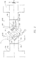
- FIG. 2 is an exploded front view of the link beam joint assembly 10 illustrated in FIG. 1 .
- This view illustrates the connection plates 16a and 18a as they would appear when the joint 19 is disconnected.
- the connection plates 16a and 18a are welded to the respective embedded plates 28a, 28b and extend away from the embedded plates.
- connection plates 16a, 16b and outside connection plates 18a, 18b each include a diagonal slot 30 and 31, respectively. These slots are diagonally opposed with a reference angle 0, typically 0' to 90'. These diagonally opposed slots allow for an imposed lateral or vertical moment in the plane of the walls 12a and 12b.
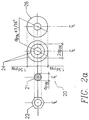
- FIG 2a is a front view of an illustrative pin assembly 20, which includes a structural steel pin (or threaded rod) 21, four steel nuts 22, and eight steel washers 24.
- the pin 21 is inserted into the diagonal slots 30 and 31 in the connection plates 16a, 16b and 18a, 18b.
- the pin 21 is then restrained to the connection plates with steel washers 24 and torqued steel nuts 22.
- the steel washers 24 are located under the steel nuts 22.
- the pin 21 is aligned through diagonally opposite slots 30 and 31.
- the pin assembly components may comprise materials other than those described above with respect to the illustrative example. Further, the pin assembly configuration may be adapted to include fewer or a greater number of components, such as additional washers or nuts.
- FIG. 3 is an exploded top view of the link beam joint assembly 10 illustrated in FIG. 1 .
- This view depicts the placement of the inner connection plates 16a, 16b and the outer connection plates 18a, 18b.
- the position of the diagonal slots 30 and 31 is also shown in this figure.
- connection plate 16a includes slot 30a
- connection plate 16b includes slot 30b
- connection plate 18a includes slot 31 a
- connection plate 18b includes slot 31b.
- the connection plates 16a, 16b and 18a, 18b extend directly outward from the embedded plates 28a, 28b, and parallel to the respective link beams 14a, 14b.
- the connection plates 16 and 18 are placed equidistant from one another relative to the center line of the plate assembly.
- FIG. 3a Illustrated in FIG. 3a , is a top view of the pin assembly 20 used to connect the plates 16a, 16b and 18a, 18b.
- This view illustrates how the pin 21, which is a threaded steel rod in the example, is fastened to the connection plates 16a, 16b and 18a, 18b with steel nuts 22 over steel washers 24.
- Brass shims 26 are placed between steel washers 24 and connection plates 16a, 16b and 18a, 18b.
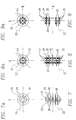
- FIG. 4 is a cross sectional view of the plate assembly 18 of FIG. 2 taken along line IV-IV'.
- the section illustrates the cross-section of the outer connection plates 18a, 18b.
- this view illustrates the position of the diagonal slots 31a, 31b relative to the horizontal center line axis 40 of the beam 14a taken along line IV-IV'.
- FIG. 5 is cross sectional view of the plate assembly 16 of FIG. 2 taken along line VV'.
- the section illustrates the cross-section of the inner connection plates 16a, 16b.
- This view illustrates the position of the diagonal slots 30a, 30b relative to the horizontal center line axis 50 of the beam 14b taken along V-V'.
- FIG. 6 is a cross sectional view of the plate assembly 16a, 16b of FIG. 2 taken along line VI-VI'. This view illustrates the connection of plates 16a, 16b normal to the embedded steel plate 28 with their position relative to the centering axis 60 of beam 14b and wall 12b beyond.
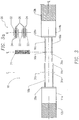
- FIG. 7 is a top view of the completed pin assembly 20 used to connect inner connection plates 16a, 16b and outer connection plates 18a, 18b utilizing a single steel threaded thru-rod 21.
- This illustrative pin assembly includes a completely threaded steel rod 21, steel nuts 22 used for torquing the rod, steel washers 24, and brass shims 26.
- FIG. 7a is a side view of the completed pin assembly 20.
- FIG. 8 is a top view of another embodiment of the completed pin assembly 20 used to connect inner connection plates 16a, 16b and outer connection plates 18a, 18b utilizing multiple steel threaded thru-rods 32.
- This pin assembly includes multiple threaded steel rods 32, steel nuts 33 used for torquing the rods, steel washers 24, brass shims 26, and a steel spacer plate 36 used to keep the rods aligned. Spacer plate 36 may use standard diameter holes to match the rod diameter.
- FIG. 8a is a side view of the completed pin assembly 20 that utilizes multiple steel threaded thru-rods 32.
- FIG. 9 is a top view of yet another embodiment of the completed pin assembly 20 used to connect inner plates 16a, 16b and outer plates 18a, 18b utilizing multiple high-strength steel bolts 34.
- This pin assembly includes high-strength steel bolts with threads excluded from the shear plane 34, steel nuts 35 used for torquing the bolts, steel washers 24, and brass shims 26.
- FIG. 9a is a side view of the completed pin assembly 20 that utilizes multiple high-strength steel bolts 34.
- FIG. 10 is a front view of one embodiment of the link beam joint assembly 10 as it would appear with the connection plates 16a, 16b and 18a, 18b connected via the link-fuse joint 19.
- This view illustrates the placement of the pin assembly 20 through connection plates 16a, 16b and 18a, 18b.
- This connection may be accomplished, for example, with a single thru-rod 21, multiple thru-rods 32, or multiple high-strength bolts 34.
- the diagonally opposed slots 30 and 31 in the connection plates 18a, 18b and 16a, 16b, respectively allow the connection plates to slide relative to one another when subject to extreme seismic loads. As the connection plates move, they are held together via the pin 20, yet are enabled to move as the pin 20 travels within the slots. The slipping that occurs between the plates 16a, 16b and 18a, 18b transfers to embedded plates 28a, 28b, thereby dissipating energy at the joint 19.
- one or more brass shims 26 may be placed, for example, between the connection plates and/or between the connection plates and adjacent washers.
- the coefficient of friction of the brass, or other material that is used, against the cleaned mill surface of structural steel, or other material, is very well understood and can be accurately predicted.
- connection plates 16a, 16b and 18a, 18b can be determined.
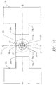
- FIG. 11 is a top view of one embodiment of the link beam joint assembly 10. This view illustrates the positioning of the connection plates 16a, 16b and 18a, 18b, relative to one another, when the joint 19 is connected, as well as embedded plates 28.
- shims 26 may be positioned, for example, between the connection plates (e. g., between connection plate 16a and connection plate 18a), between the connection plates and interior washers (e. g., between connection plate 16b and washer 24), and/or between the connection plates and exterior washers (e. g., between connection plate 18b and washer 24.)
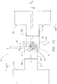
- FIG. 12 is a side view and FIG. 13 is a perspective view of the link-fuse joint 19 as it would appear slipped when placed under a severe seismic load.
- shear forces and bending moments are introduced into the wall 12a, 12b from ground motions due to seismic activity.
- the link-fuse joint 19 will slip, as shown in FIG. 12 and FIG. 13 .
- the joint 19 will slide about the pin 21 (or 32 or 34) connection, which is created through the introduction of the pin assembly 20 into the connection plates 16a, 16b and 18a, 18b while using diagonally opposed slots 30 and 31. Shear loads are transferred to the link beam 14a, 14b then to the shear wall 12a, 12b through this pin connection.
- the wall 12a has shifted, for example, toward the upper left relative to the joint 19, such that the pin 21 has slid to the base of slot 31, while the pin 21 has not changed position within slot 30.
- the pin 21 could however change position within slot 30 during overall shifting of the structure.
- the diagonally opposed slots enable the pin 21 to maintain a connection within the joint 19 when the walls 12a, 12b move relative to each other.
- link-fuse joint 19 within a building frame may include the introduction of the joint 19 into other structural support members in addition to the beam, such as the shear wall 12, primarily at the base of the shear walls 12.
- Other materials may be considered for the building frame and joint 10, including, but are not limited to, composite resin materials such as fiberglass.
- Alternate structural steel shapes may also be used in the link-fuse joints 19, including, but not limited to, built-up sections, e. g., welded plates, or other rolled shaped such as channels.
- Alternative materials (other than brass) may also be used between the connection plates 16a, 16b and 18a, 18b to achieve a predictable slip threshold.
- Such materials may include, but not be limited to, Teflon, bronze or steel with a controlled mill finish. Steel, Teflon, bronze or other materials may also be used in place of the brass shims 26 in the plate end connection.
Landscapes
- Engineering & Computer Science (AREA)
- Architecture (AREA)
- Business, Economics & Management (AREA)
- Emergency Management (AREA)
- Environmental & Geological Engineering (AREA)
- Civil Engineering (AREA)
- Structural Engineering (AREA)
- Buildings Adapted To Withstand Abnormal External Influences (AREA)
- Joining Of Building Structures In Genera (AREA)
- Vibration Prevention Devices (AREA)
- Vibration Dampers (AREA)
Claims (18)
- Gelenkverbindung, die eine laterale und vertikale Relativbewegung zwischen verbundenen Wänden während seismischer Aktivität aufnimmt, wobei die Gelenkverbindung Folgendes umfasst:eine erste Plattenanordnung mit (a) zwei oder mehr parallelen ersten Verbindungsplatten (18a, 18b), die jeweils einen dort hindurch ausgebildeten ersten diagonalen Schlitz (31) beinhalten, der sich entlang einer ersten diagonalen Richtung erstreckt, und (b) einer ersten befestigbaren Platte (28a), an der die ersten Verbindungsplatten unbeweglich fixiert sind, wobei die ersten diagonalen Schlitze zueinander fluchtend ausgerichtet sind, wobei die erste befestigbare Platte (28a) an einem ersten Stützelement (12a oder 14a) befestigt ist, das ein Teil einer ersten Wand oder damit verbunden ist, wobei sich die zwei oder mehr ersten Verbindungsplatten entlang einer lateralen Richtung von der ersten befestigbaren Platte und in parallelen ersten Ebenen erstrecken, wobei der erste diagonale Schlitz relativ zu einer vertikalen Richtung diagonal ist, die zur lateralen Richtung orthogonal ist;eine zweite Plattenanordnung mit (a) zumindest einer zweiten Verbindungsplatte (16a oder 16b), wobei die zumindest eine zweite Verbindungsplatte zwischen zwei der ersten Verbindungsplatten angeordnet ist und einen dort hindurch ausgebildeten zweiten diagonalen Schlitz (30) beinhaltet, der sich entlang einer zweiten diagonalen Richtung erstreckt, und (b) einer zweiten befestigbaren Platte (28b), an der die zumindest eine zweite Verbindungsplatte unbeweglich befestigt ist, wobei die zweite befestigbare Platte (28b) an einem zweiten Stützelement (12b oder 14b) befestigt ist, das ein Teil einer zweiten Wand oder damit verbunden ist, wobei sich jede zweite Verbindungsplatte (16a, 16b) entlang der lateralen Richtung in einer jeweiligen zweiten Ebene erstreckt, die parallel zu den ersten Ebenen ist, wobei der zweite diagonale Schlitz dem ersten diagonalen Schlitz relativ zur vertikalen Richtung diagonal entgegengesetzt ist, so dass die erste diagonale Richtung und die zweite diagonale Richtung einander schneiden, wobei jede zweite Verbindungsplatte so angeordnet ist, dass zumindest ein Abschnitt ihres zweiten diagonalen Schlitzes zu jedem anderen zweiten diagonalen Schlitz fluchtend ausgerichtet ist und einen Abschnitt jedes ersten diagonalen Schlitzes überlappt; undeine Stiftanordnung (20), die die erste Plattenanordnung und die zweite Plattenanordnung mit einer Klemmkraft zusammenklemmt und einen Stift (21) beinhaltet, der sich durch jeden ersten diagonalen Schlitz und jeden zweiten diagonalen Schlitz erstreckt, wobei die Gelenkverbindung ein laterales Verrutschen entlang der lateralen Richtung, ein vertikales Verrutschen entlang der vertikalen Richtung oder beides der ersten Plattenanordnung und der zweiten Plattenanordnung relativ zueinander erlaubt, wenn die Gelenkverbindung einer seismischen Belastung unterliegt, jedoch ohne signifikanten Verlust der Klemmkraft.
- Gelenkverbindung nach Anspruch 1, wobei jede von zwei entgegengesetzt gerichteten Seiten der zumindest einen zweiten Verbindungsplatte an einer jeweiligen der zwei ersten Verbindungsplatten anliegt.
- Gelenkverbindung nach Anspruch 1, umfassend mehrere der zweiten Verbindungsplatten (16a und 16b), wobei die zweiten diagonalen Schlitze der mehreren zweiten Verbindungsplatten zueinander fluchtend ausgerichtet sind.
- Gelenkverbindung nach Anspruch 1, wobei die erste befestigbare Platte an einem ersten Träger befestigt ist, der sich lateral von der ersten Wand erstreckt, und die zweite befestigbare Platte an einem zweiten Träger befestigt ist, der sich lateral von der zweiten Wand erstreckt.
- Gelenkverbindung nach Anspruch 4, wobei zumindest eines des ersten Stützelements oder des zweiten Stützelements ein sich lateral erstreckender Träger (14a oder 14b) ist.
- Gelenkverbindung nach Anspruch 4, wobei zumindest eines des ersten Stützelements oder des zweiten Stützelements eine Scherwand (12a oder 12b) ist.
- Gelenkverbindung nach Anspruch 4, wobei zumindest eines des ersten Stützelements oder des zweiten Stützelements aus Baustahl besteht.
- Gelenkverbindung nach Anspruch 4, wobei zumindest eines des ersten Stützelements oder des zweiten Stützelements aus Stahlbeton besteht.
- Gelenkverbindung nach Anspruch 4, wobei zumindest eines des ersten Stützelements oder des zweiten Stützelements aus einem Verbundwerkstoff besteht.
- Gelenkverbindung nach Anspruch 1, ferner umfassend eine Beilagscheibe (26), die zwischen einer der ersten Verbindungsplatten und der zumindest einen zweiten Verbindungsplatte angeordnet ist.
- Gelenkverbindung nach Anspruch 10, wobei die Beilagscheibe Messing umfasst.
- Gelenkverbindung nach Anspruch 10, wobei die Beilagscheibe Stahl umfasst.
- Gelenkverbindung nach Anspruch 10, wobei die Beilagscheibe Teflon umfasst.
- Gelenkverbindung nach Anspruch 10, wobei die Beilagscheibe Bronze umfasst.
- Gelenkverbindung nach Anspruch 1, wobei der Stift (21) eines aus einer Gewindestahlstange, mehreren Gewindestahlstangen und mehreren hochfesten Bolzen umfasst.
- Gelenkverbindung nach Anspruch 1, wobei im montierten Zustand jede der ersten und zweiten Plattenanordnung an einem jeweiligen Verbindungsträger (14a, 14b) angebracht ist, so dass sich jede erste Verbindungsplatte und die zumindest eine zweite Verbindungsplatte von dem Verbindungsträger, an dem seine jeweilige Plattenanordnung angebracht ist, weg erstrecken und zu ihm parallel sind und die ersten diagonalen Schlitze und der zumindest eine zweite diagonale Schlitz dem Stift (21) ermöglichen, sich lateral und vertikal innerhalb eines jeweiligen der Schlitze (30, 31) zu bewegen, und zwar als Reaktion auf eine entsprechende seismisch induzierte Bewegung eines der Verbindungsträger.
- Gelenkverbindung nach Anspruch 16, ferner umfassend eine Beilagscheibe (26), die zwischen einer der ersten Verbindungsplatten und der zumindest einen zweiten Verbindungsplatte angeordnet ist und eine Öffnung aufweist, durch die sich der Stift erstreckt, wobei die Beilagscheibe ausgelegt ist, um eine Bewegung des Stifts innerhalb entweder der ersten diagonalen Schlitze oder des zumindest einen zweiten diagonalen Schlitzes zu verhindern, wenn der Stift einer Scherkraft auf oder unterhalb eines vorbestimmten Niveaus unterliegt, wobei die Beilagscheibe Messing, Stahl, Teflon oder Bronze umfasst.
- Gelenkverbindung nach Anspruch 1, umfassend nur zwei erste Verbindungsplatten und nur eine zweite Verbindungsplatte, die zwischen den nur zwei ersten Verbindungsplatten angeordnet ist, wobei die nur eine zweite Verbindungsplatte in einer Richtung zwischen den nur zwei ersten Verbindungsplatten breiter als die nur zwei ersten Verbindungsplatten ist, wobei entgegengesetzt gerichtete Seiten der nur einen zweiten Verbindungsplatte an einer jeweiligen der nur zwei ersten Verbindungsplatten anliegen.
Applications Claiming Priority (2)
| Application Number | Priority Date | Filing Date | Title |
|---|---|---|---|
| US11/751,156 US7647734B2 (en) | 2007-05-21 | 2007-05-21 | Seismic structural device |
| PCT/US2008/062728 WO2008147642A1 (en) | 2007-05-21 | 2008-05-06 | Seismic structural device |
Publications (3)
| Publication Number | Publication Date |
|---|---|
| EP2147170A1 EP2147170A1 (de) | 2010-01-27 |
| EP2147170A4 EP2147170A4 (de) | 2016-08-10 |
| EP2147170B1 true EP2147170B1 (de) | 2021-05-05 |
Family
ID=40071100
Family Applications (1)
| Application Number | Title | Priority Date | Filing Date |
|---|---|---|---|
| EP08747677.6A Active EP2147170B1 (de) | 2007-05-21 | 2008-05-06 | Seismisches strukturelement |
Country Status (8)
| Country | Link |
|---|---|
| US (1) | US7647734B2 (de) |
| EP (1) | EP2147170B1 (de) |
| JP (1) | JP5123378B2 (de) |
| CN (1) | CN101680223B (de) |
| CA (1) | CA2687090C (de) |
| ES (1) | ES2870998T3 (de) |
| PT (1) | PT2147170T (de) |
| WO (1) | WO2008147642A1 (de) |
Families Citing this family (30)
| Publication number | Priority date | Publication date | Assignee | Title |
|---|---|---|---|---|
| US8001734B2 (en) | 2004-05-18 | 2011-08-23 | Simpson Strong-Tie Co., Inc. | Moment frame links wall |
| US7647734B2 (en) * | 2007-05-21 | 2010-01-19 | Skidmore Owings & Merrill Llp | Seismic structural device |
| CN102782227B (zh) * | 2009-10-02 | 2014-11-26 | 减振技术公司 | 阻尼系统 |
| US8452573B2 (en) * | 2010-01-29 | 2013-05-28 | Skidmore, Owings & Merrill Llp | Carbon footprint analysis tool for structures |
| JP4729134B1 (ja) * | 2010-06-16 | 2011-07-20 | 新日本製鐵株式会社 | 制震用金属板及び建築構造物 |
| ES2585208T3 (es) * | 2011-07-15 | 2016-10-04 | Damptech A/S | Amortiguador pasivo |
| US8393118B2 (en) * | 2011-12-22 | 2013-03-12 | General Electric Company | Friction damping bolt connection for a wind tower lattice structure |
| US9631391B2 (en) * | 2013-04-08 | 2017-04-25 | Nippon Steel & Sumikin Engineering Co., Ltd | Buckling restrained brace and load-bearing structure provided with the same |
| CN104032858B (zh) * | 2014-05-15 | 2016-06-29 | 中国建筑股份有限公司 | 装配式钢梁接缝一字形混合连肢墙及其施工方法 |
| CN104032855B (zh) * | 2014-05-15 | 2016-08-24 | 中国建筑股份有限公司 | 装配式十字形混合连肢墙及其施工方法 |
| CN106320560B (zh) * | 2016-11-11 | 2020-09-11 | 华东建筑设计研究院有限公司 | 一种装配式结构的阻尼器 |
| CN106545107B (zh) * | 2016-12-08 | 2022-06-07 | 华侨大学 | 具有自复位功能的钢筋混凝土混合剪力墙 |
| CN106703245B (zh) * | 2016-12-08 | 2022-07-29 | 华侨大学 | 震损部位可更换的钢筋混凝土混合剪力墙 |
| KR20180072034A (ko) * | 2016-12-20 | 2018-06-29 | 단국대학교 산학협력단 | 계단실과 본 건물의 사이를 활용한 감쇠시스템 |
| US10544577B2 (en) * | 2017-04-13 | 2020-01-28 | Novel Structures, LLC | Member-to-member laminar fuse connection |
| CA3059998C (en) * | 2017-04-13 | 2023-02-28 | Novel Structures, LLC | Member-to-member laminar fuse connection |
| GB2554967B (en) * | 2017-06-12 | 2020-12-09 | Eqrbs Ltd | A joint |
| US11280080B2 (en) | 2017-06-12 | 2022-03-22 | Peter James Bucklitsch | Kit for defining a recess for a single or multi-way joint |
| CN107724544A (zh) * | 2017-11-13 | 2018-02-23 | 中国地震局工程力学研究所 | 装配式剪力墙间的竖向多铰连接结构及施工方法 |
| CN108331191B (zh) * | 2018-01-31 | 2023-07-25 | 广州大学 | 一种圆盘放大阻尼器 |
| CN109826480B (zh) * | 2019-02-28 | 2020-08-11 | 长安大学 | 单向阻尼铰装置及应用其进行结构被动振动控制的方法 |
| CN109972732B (zh) * | 2019-03-08 | 2020-08-04 | 邢台职业技术学院 | 一种建筑承重结构 |
| US11286683B2 (en) * | 2019-03-12 | 2022-03-29 | Idaho State University | Ductile connections for pre-formed construction elements |
| CN110080591A (zh) * | 2019-04-18 | 2019-08-02 | 济南大学 | 一种钢框架梁柱抗震耗能连接件及其设计方法 |
| US11512461B2 (en) * | 2019-05-06 | 2022-11-29 | Stanislav BERDICHEVSKY | Engineered beam with adjustable angle connection |
| US11396746B2 (en) * | 2019-06-14 | 2022-07-26 | Quaketek Inc. | Beam coupler operating as a seismic brake, seismic energy dissipation device and seismic damage control device |
| CN113356669B (zh) * | 2020-07-20 | 2022-08-12 | 长江师范学院 | 一种双重减震效果的建筑保护装置 |
| CN111749327A (zh) * | 2020-07-31 | 2020-10-09 | 西安建筑科技大学 | 一种装配式混凝土梁柱耗能连接键 |
| CN112555319B (zh) * | 2020-12-01 | 2022-07-26 | 故宫博物院 | 一种适用于通体展柜的文物隔震装置 |
| CN115492234B (zh) * | 2022-08-26 | 2024-12-17 | 华南理工大学 | 一种双向变形协同和多阶段工作的摩擦消能柱 |
Citations (1)
| Publication number | Priority date | Publication date | Assignee | Title |
|---|---|---|---|---|
| US2877875A (en) * | 1956-09-12 | 1959-03-17 | Deere & Co | Adjustable support for partition-to-floor mountings |
Family Cites Families (35)
| Publication number | Priority date | Publication date | Assignee | Title |
|---|---|---|---|---|
| US2733786A (en) * | 1951-12-21 | 1956-02-07 | Drake | |
| US2990920A (en) * | 1958-01-21 | 1961-07-04 | Republic Steel Corp | Structural building elements |
| US3490797A (en) * | 1968-12-17 | 1970-01-20 | Eugene L Platte | Clip assembly |
| US3798865A (en) * | 1972-03-17 | 1974-03-26 | Integrated Ceilings Inc | Grid support structure and clip means therefor |
| US4035093A (en) * | 1976-03-01 | 1977-07-12 | The Boeing Company | Bi-directional adjustable couplings |
| US4557457A (en) * | 1984-02-06 | 1985-12-10 | Frame-Lok, Inc. | Attachment assembly |
| US4577729A (en) * | 1984-12-05 | 1986-03-25 | Westinghouse Electric Corp. | Guide rail clamping assembly |
| US5048243A (en) * | 1988-03-11 | 1991-09-17 | Ward John D | Earthquake restraint mechanism |
| GB8911779D0 (en) * | 1989-05-23 | 1989-07-12 | Jaguar Cars | Adjustable bracket |
| JP2796997B2 (ja) * | 1989-08-03 | 1998-09-10 | 株式会社竹中工務店 | ボルト締めによる制震用ダンパー |
| JP3156007B2 (ja) * | 1991-09-27 | 2001-04-16 | 株式会社竹中工務店 | 周期的エネルギーの吸収装置 |
| US5375382A (en) * | 1992-01-21 | 1994-12-27 | Weidlinger; Paul | Lateral force resisting structures and connections therefor |
| US5375385A (en) * | 1993-01-28 | 1994-12-27 | Feder; David | Contoured marble and method of fabrication |
| US5420762A (en) * | 1993-09-24 | 1995-05-30 | Trw Inc. | Automotive headlamp assembly fastening system |
| US5720571A (en) * | 1994-12-22 | 1998-02-24 | Super Stud Building Products, Inc. | Deflection slide clip |
| US5846018A (en) * | 1996-08-26 | 1998-12-08 | Super Stud Building Products, Inc. | Deflection slide clip |
| JP3329698B2 (ja) * | 1997-07-17 | 2002-09-30 | 昭和電線電纜株式会社 | 動吸振器 |
| US5876006A (en) * | 1997-08-22 | 1999-03-02 | Scafco Corporation | Stud mounting clip |
| JPH11124926A (ja) * | 1997-10-22 | 1999-05-11 | Kawakubo Kensetsu Kk | 建築構造体およびその組立方法 |
| JP2000352113A (ja) * | 1999-04-06 | 2000-12-19 | Ohbayashi Corp | ボルト接合部の制振構造 |
| US6196356B1 (en) * | 1999-08-24 | 2001-03-06 | Terryle L. Sneed | Method and apparatus for installing elevator car and counterweight guide rails |
| US6213679B1 (en) * | 1999-10-08 | 2001-04-10 | Super Stud Building Products, Inc. | Deflection slide clip |
| US6688069B2 (en) * | 2000-07-24 | 2004-02-10 | Unimast Incorporated | Vertical slide clip |
| CA2446498A1 (en) * | 2001-05-09 | 2002-11-14 | Damptech Aps | Frictional damper for damping movement of structures |
| JP4615790B2 (ja) * | 2001-09-25 | 2011-01-19 | 大和ハウス工業株式会社 | 摩擦ダンパー |
| JP2003307253A (ja) * | 2002-04-12 | 2003-10-31 | Ohbayashi Corp | 摩擦ダンパー |
| US6681538B1 (en) * | 2002-07-22 | 2004-01-27 | Skidmore, Owings & Merrill Llp | Seismic structural device |
| US6994385B2 (en) * | 2003-10-23 | 2006-02-07 | Sigears John M | Arrow extractor |
| WO2005067828A2 (en) * | 2004-01-07 | 2005-07-28 | Dj Orthopedics, Llc | Knee brace hinges with adaptive motion |
| US7293393B2 (en) * | 2004-01-27 | 2007-11-13 | Worthington Armstrong Venture | Perimeter clip for seismic ceilings |
| TWI242628B (en) * | 2004-06-04 | 2005-11-01 | Ind Tech Res Inst | Seismic-protection wheel locational anchorage |
| JP4775808B2 (ja) * | 2004-12-03 | 2011-09-21 | 株式会社不二越 | 免震部品ユニット及び免震装置 |
| JP2007040063A (ja) * | 2005-08-05 | 2007-02-15 | Daiwa House Ind Co Ltd | ブレース構造 |
| US7306191B1 (en) * | 2006-09-01 | 2007-12-11 | Bi-Ju Chen | Suspension structure for a ceiling fan |
| US7647734B2 (en) * | 2007-05-21 | 2010-01-19 | Skidmore Owings & Merrill Llp | Seismic structural device |
-
2007
- 2007-05-21 US US11/751,156 patent/US7647734B2/en active Active
-
2008
- 2008-05-06 CA CA2687090A patent/CA2687090C/en active Active
- 2008-05-06 PT PT87476776T patent/PT2147170T/pt unknown
- 2008-05-06 WO PCT/US2008/062728 patent/WO2008147642A1/en not_active Ceased
- 2008-05-06 CN CN2008800171883A patent/CN101680223B/zh active Active
- 2008-05-06 ES ES08747677T patent/ES2870998T3/es active Active
- 2008-05-06 JP JP2010509427A patent/JP5123378B2/ja active Active
- 2008-05-06 EP EP08747677.6A patent/EP2147170B1/de active Active
Patent Citations (1)
| Publication number | Priority date | Publication date | Assignee | Title |
|---|---|---|---|---|
| US2877875A (en) * | 1956-09-12 | 1959-03-17 | Deere & Co | Adjustable support for partition-to-floor mountings |
Also Published As
| Publication number | Publication date |
|---|---|
| CN101680223A (zh) | 2010-03-24 |
| US20080289268A1 (en) | 2008-11-27 |
| ES2870998T3 (es) | 2021-10-28 |
| US7647734B2 (en) | 2010-01-19 |
| CN101680223B (zh) | 2012-12-26 |
| CA2687090C (en) | 2015-06-23 |
| EP2147170A4 (de) | 2016-08-10 |
| CA2687090A1 (en) | 2008-12-04 |
| JP2010528234A (ja) | 2010-08-19 |
| WO2008147642A1 (en) | 2008-12-04 |
| PT2147170T (pt) | 2021-06-01 |
| EP2147170A1 (de) | 2010-01-27 |
| JP5123378B2 (ja) | 2013-01-23 |
Similar Documents
| Publication | Publication Date | Title |
|---|---|---|
| EP2147170B1 (de) | Seismisches strukturelement | |
| EP2147171B1 (de) | Anti-seismische verbindung und entsprechende rahmenstruktur | |
| US6681538B1 (en) | Seismic structural device | |
| JP5398980B2 (ja) | モーメントフレーム連結 | |
| US7637076B2 (en) | Moment-resistant building column insert system and method | |
| US6012256A (en) | Moment-resistant structure, sustainer and method of resisting episodic loads | |
| US9683365B2 (en) | Piston based self-centering brace apparatus | |
| CN113863531B (zh) | 地震屈服连接 | |
| EP3262245B1 (de) | Scharnierzelle für eine verbindung zwischen träger und stütze | |
| HK1140525B (en) | Seismic structural device | |
| JP2000120299A (ja) | 構造物用制振装置 | |
| JP4379732B2 (ja) | 建物の耐震補強工法 | |
| HK1140526B (en) | Anti-seinsmic joint connection and corresponding structural frame | |
| HK1140526A (en) | Anti-seinsmic joint connection and corresponding structural frame |
Legal Events
| Date | Code | Title | Description |
|---|---|---|---|
| PUAI | Public reference made under article 153(3) epc to a published international application that has entered the european phase |
Free format text: ORIGINAL CODE: 0009012 |
|
| 17P | Request for examination filed |
Effective date: 20091116 |
|
| AK | Designated contracting states |
Kind code of ref document: A1 Designated state(s): AT BE BG CH CY CZ DE DK EE ES FI FR GB GR HR HU IE IS IT LI LT LU LV MC MT NL NO PL PT RO SE SI SK TR |
|
| AX | Request for extension of the european patent |
Extension state: AL BA MK RS |
|
| DAX | Request for extension of the european patent (deleted) | ||
| REG | Reference to a national code |
Ref country code: HK Ref legal event code: DE Ref document number: 1140525 Country of ref document: HK |
|
| RA4 | Supplementary search report drawn up and despatched (corrected) |
Effective date: 20160713 |
|
| RIC1 | Information provided on ipc code assigned before grant |
Ipc: E04H 9/02 20060101ALI20160707BHEP Ipc: E04B 1/24 20060101ALI20160707BHEP Ipc: E04B 1/98 20060101AFI20160707BHEP |
|
| STAA | Information on the status of an ep patent application or granted ep patent |
Free format text: STATUS: EXAMINATION IS IN PROGRESS |
|
| 17Q | First examination report despatched |
Effective date: 20170831 |
|
| GRAP | Despatch of communication of intention to grant a patent |
Free format text: ORIGINAL CODE: EPIDOSNIGR1 |
|
| STAA | Information on the status of an ep patent application or granted ep patent |
Free format text: STATUS: GRANT OF PATENT IS INTENDED |
|
| INTG | Intention to grant announced |
Effective date: 20201207 |
|
| GRAS | Grant fee paid |
Free format text: ORIGINAL CODE: EPIDOSNIGR3 |
|
| GRAA | (expected) grant |
Free format text: ORIGINAL CODE: 0009210 |
|
| STAA | Information on the status of an ep patent application or granted ep patent |
Free format text: STATUS: THE PATENT HAS BEEN GRANTED |
|
| AK | Designated contracting states |
Kind code of ref document: B1 Designated state(s): AT BE BG CH CY CZ DE DK EE ES FI FR GB GR HR HU IE IS IT LI LT LU LV MC MT NL NO PL PT RO SE SI SK TR |
|
| REG | Reference to a national code |
Ref country code: GB Ref legal event code: FG4D |
|
| REG | Reference to a national code |
Ref country code: CH Ref legal event code: EP |
|
| REG | Reference to a national code |
Ref country code: AT Ref legal event code: REF Ref document number: 1389980 Country of ref document: AT Kind code of ref document: T Effective date: 20210515 |
|
| REG | Reference to a national code |
Ref country code: DE Ref legal event code: R096 Ref document number: 602008063934 Country of ref document: DE |
|
| REG | Reference to a national code |
Ref country code: IE Ref legal event code: FG4D |
|
| REG | Reference to a national code |
Ref country code: PT Ref legal event code: SC4A Ref document number: 2147170 Country of ref document: PT Date of ref document: 20210601 Kind code of ref document: T Free format text: AVAILABILITY OF NATIONAL TRANSLATION Effective date: 20210524 |
|
| REG | Reference to a national code |
Ref country code: RO Ref legal event code: EPE |
|
| REG | Reference to a national code |
Ref country code: SE Ref legal event code: TRGR |
|
| REG | Reference to a national code |
Ref country code: LT Ref legal event code: MG9D |
|
| REG | Reference to a national code |
Ref country code: GR Ref legal event code: EP Ref document number: 20210401945 Country of ref document: GR Effective date: 20210813 |
|
| REG | Reference to a national code |
Ref country code: ES Ref legal event code: FG2A Ref document number: 2870998 Country of ref document: ES Kind code of ref document: T3 Effective date: 20211028 |
|
| PG25 | Lapsed in a contracting state [announced via postgrant information from national office to epo] |
Ref country code: LT Free format text: LAPSE BECAUSE OF FAILURE TO SUBMIT A TRANSLATION OF THE DESCRIPTION OR TO PAY THE FEE WITHIN THE PRESCRIBED TIME-LIMIT Effective date: 20210505 Ref country code: FI Free format text: LAPSE BECAUSE OF FAILURE TO SUBMIT A TRANSLATION OF THE DESCRIPTION OR TO PAY THE FEE WITHIN THE PRESCRIBED TIME-LIMIT Effective date: 20210505 Ref country code: HR Free format text: LAPSE BECAUSE OF FAILURE TO SUBMIT A TRANSLATION OF THE DESCRIPTION OR TO PAY THE FEE WITHIN THE PRESCRIBED TIME-LIMIT Effective date: 20210505 Ref country code: BG Free format text: LAPSE BECAUSE OF FAILURE TO SUBMIT A TRANSLATION OF THE DESCRIPTION OR TO PAY THE FEE WITHIN THE PRESCRIBED TIME-LIMIT Effective date: 20210805 |
|
| PG25 | Lapsed in a contracting state [announced via postgrant information from national office to epo] |
Ref country code: LV Free format text: LAPSE BECAUSE OF FAILURE TO SUBMIT A TRANSLATION OF THE DESCRIPTION OR TO PAY THE FEE WITHIN THE PRESCRIBED TIME-LIMIT Effective date: 20210505 Ref country code: PL Free format text: LAPSE BECAUSE OF FAILURE TO SUBMIT A TRANSLATION OF THE DESCRIPTION OR TO PAY THE FEE WITHIN THE PRESCRIBED TIME-LIMIT Effective date: 20210505 Ref country code: NO Free format text: LAPSE BECAUSE OF FAILURE TO SUBMIT A TRANSLATION OF THE DESCRIPTION OR TO PAY THE FEE WITHIN THE PRESCRIBED TIME-LIMIT Effective date: 20210805 |
|
| REG | Reference to a national code |
Ref country code: AT Ref legal event code: UEP Ref document number: 1389980 Country of ref document: AT Kind code of ref document: T Effective date: 20210505 |
|
| REG | Reference to a national code |
Ref country code: NL Ref legal event code: MP Effective date: 20210505 |
|
| PG25 | Lapsed in a contracting state [announced via postgrant information from national office to epo] |
Ref country code: NL Free format text: LAPSE BECAUSE OF FAILURE TO SUBMIT A TRANSLATION OF THE DESCRIPTION OR TO PAY THE FEE WITHIN THE PRESCRIBED TIME-LIMIT Effective date: 20210505 |
|
| PG25 | Lapsed in a contracting state [announced via postgrant information from national office to epo] |
Ref country code: SK Free format text: LAPSE BECAUSE OF FAILURE TO SUBMIT A TRANSLATION OF THE DESCRIPTION OR TO PAY THE FEE WITHIN THE PRESCRIBED TIME-LIMIT Effective date: 20210505 Ref country code: EE Free format text: LAPSE BECAUSE OF FAILURE TO SUBMIT A TRANSLATION OF THE DESCRIPTION OR TO PAY THE FEE WITHIN THE PRESCRIBED TIME-LIMIT Effective date: 20210505 Ref country code: DK Free format text: LAPSE BECAUSE OF FAILURE TO SUBMIT A TRANSLATION OF THE DESCRIPTION OR TO PAY THE FEE WITHIN THE PRESCRIBED TIME-LIMIT Effective date: 20210505 Ref country code: CZ Free format text: LAPSE BECAUSE OF FAILURE TO SUBMIT A TRANSLATION OF THE DESCRIPTION OR TO PAY THE FEE WITHIN THE PRESCRIBED TIME-LIMIT Effective date: 20210505 Ref country code: LU Free format text: LAPSE BECAUSE OF NON-PAYMENT OF DUE FEES Effective date: 20210506 |
|
| REG | Reference to a national code |
Ref country code: DE Ref legal event code: R097 Ref document number: 602008063934 Country of ref document: DE |
|
| PLBE | No opposition filed within time limit |
Free format text: ORIGINAL CODE: 0009261 |
|
| STAA | Information on the status of an ep patent application or granted ep patent |
Free format text: STATUS: NO OPPOSITION FILED WITHIN TIME LIMIT |
|
| PG25 | Lapsed in a contracting state [announced via postgrant information from national office to epo] |
Ref country code: MC Free format text: LAPSE BECAUSE OF FAILURE TO SUBMIT A TRANSLATION OF THE DESCRIPTION OR TO PAY THE FEE WITHIN THE PRESCRIBED TIME-LIMIT Effective date: 20210505 |
|
| 26N | No opposition filed |
Effective date: 20220208 |
|
| PG25 | Lapsed in a contracting state [announced via postgrant information from national office to epo] |
Ref country code: IE Free format text: LAPSE BECAUSE OF NON-PAYMENT OF DUE FEES Effective date: 20210506 |
|
| PG25 | Lapsed in a contracting state [announced via postgrant information from national office to epo] |
Ref country code: HU Free format text: LAPSE BECAUSE OF FAILURE TO SUBMIT A TRANSLATION OF THE DESCRIPTION OR TO PAY THE FEE WITHIN THE PRESCRIBED TIME-LIMIT; INVALID AB INITIO Effective date: 20080506 Ref country code: CY Free format text: LAPSE BECAUSE OF FAILURE TO SUBMIT A TRANSLATION OF THE DESCRIPTION OR TO PAY THE FEE WITHIN THE PRESCRIBED TIME-LIMIT Effective date: 20210505 |
|
| PG25 | Lapsed in a contracting state [announced via postgrant information from national office to epo] |
Ref country code: MT Free format text: LAPSE BECAUSE OF FAILURE TO SUBMIT A TRANSLATION OF THE DESCRIPTION OR TO PAY THE FEE WITHIN THE PRESCRIBED TIME-LIMIT Effective date: 20210505 |
|
| PGFP | Annual fee paid to national office [announced via postgrant information from national office to epo] |
Ref country code: SE Payment date: 20250310 Year of fee payment: 18 |
|
| PGFP | Annual fee paid to national office [announced via postgrant information from national office to epo] |
Ref country code: FR Payment date: 20250310 Year of fee payment: 18 |
|
| PGFP | Annual fee paid to national office [announced via postgrant information from national office to epo] |
Ref country code: GB Payment date: 20250313 Year of fee payment: 18 |
|
| PGFP | Annual fee paid to national office [announced via postgrant information from national office to epo] |
Ref country code: DE Payment date: 20250311 Year of fee payment: 18 |
|
| PGFP | Annual fee paid to national office [announced via postgrant information from national office to epo] |
Ref country code: ES Payment date: 20250603 Year of fee payment: 18 |
|
| PGFP | Annual fee paid to national office [announced via postgrant information from national office to epo] |
Ref country code: IS Payment date: 20250429 Year of fee payment: 18 |
|
| PGFP | Annual fee paid to national office [announced via postgrant information from national office to epo] |
Ref country code: BE Payment date: 20250410 Year of fee payment: 18 Ref country code: IT Payment date: 20250422 Year of fee payment: 18 |
|
| PGFP | Annual fee paid to national office [announced via postgrant information from national office to epo] |
Ref country code: PT Payment date: 20250506 Year of fee payment: 18 |
|
| PGFP | Annual fee paid to national office [announced via postgrant information from national office to epo] |
Ref country code: GR Payment date: 20250416 Year of fee payment: 18 |
|
| PGFP | Annual fee paid to national office [announced via postgrant information from national office to epo] |
Ref country code: CH Payment date: 20250601 Year of fee payment: 18 |
|
| PGFP | Annual fee paid to national office [announced via postgrant information from national office to epo] |
Ref country code: RO Payment date: 20250409 Year of fee payment: 18 Ref country code: AT Payment date: 20250425 Year of fee payment: 18 |
|
| PGFP | Annual fee paid to national office [announced via postgrant information from national office to epo] |
Ref country code: TR Payment date: 20250425 Year of fee payment: 18 |