EP2146140B1 - Dispositif d'éclairage réglable - Google Patents
Dispositif d'éclairage réglable Download PDFInfo
- Publication number
- EP2146140B1 EP2146140B1 EP20090164890 EP09164890A EP2146140B1 EP 2146140 B1 EP2146140 B1 EP 2146140B1 EP 20090164890 EP20090164890 EP 20090164890 EP 09164890 A EP09164890 A EP 09164890A EP 2146140 B1 EP2146140 B1 EP 2146140B1
- Authority
- EP
- European Patent Office
- Prior art keywords
- clip
- light
- support
- bearing shoe
- opening
- Prior art date
- Legal status (The legal status is an assumption and is not a legal conclusion. Google has not performed a legal analysis and makes no representation as to the accuracy of the status listed.)
- Not-in-force
Links
Images

Classifications
-
- F—MECHANICAL ENGINEERING; LIGHTING; HEATING; WEAPONS; BLASTING
- F21—LIGHTING
- F21V—FUNCTIONAL FEATURES OR DETAILS OF LIGHTING DEVICES OR SYSTEMS THEREOF; STRUCTURAL COMBINATIONS OF LIGHTING DEVICES WITH OTHER ARTICLES, NOT OTHERWISE PROVIDED FOR
- F21V21/00—Supporting, suspending, or attaching arrangements for lighting devices; Hand grips
- F21V21/14—Adjustable mountings
- F21V21/30—Pivoted housings or frames
-
- F—MECHANICAL ENGINEERING; LIGHTING; HEATING; WEAPONS; BLASTING
- F21—LIGHTING
- F21S—NON-PORTABLE LIGHTING DEVICES; SYSTEMS THEREOF; VEHICLE LIGHTING DEVICES SPECIALLY ADAPTED FOR VEHICLE EXTERIORS
- F21S8/00—Lighting devices intended for fixed installation
- F21S8/02—Lighting devices intended for fixed installation of recess-mounted type, e.g. downlighters
-
- F—MECHANICAL ENGINEERING; LIGHTING; HEATING; WEAPONS; BLASTING
- F21—LIGHTING
- F21V—FUNCTIONAL FEATURES OR DETAILS OF LIGHTING DEVICES OR SYSTEMS THEREOF; STRUCTURAL COMBINATIONS OF LIGHTING DEVICES WITH OTHER ARTICLES, NOT OTHERWISE PROVIDED FOR
- F21V21/00—Supporting, suspending, or attaching arrangements for lighting devices; Hand grips
- F21V21/02—Wall, ceiling, or floor bases; Fixing pendants or arms to the bases
- F21V21/04—Recessed bases
Definitions
- recessed spotlights, ceiling lights or pendant lights which usually have a mounting ring or an annular support body, a holding or rotating ring and a housing with a reflector and a socket for a lamp.
- the mounting ring is permanently attached in a designated mounting cutout in a mostly flat building cutout.
- On the rotary ring means for fixing the reflector and the lamp are provided.
- the rotary ring is connected to the mounting ring, so that they are mutually rotatable about their geometric center or its axis. If, for example, the reflector is fastened in a position inclined to the installation axis, then the beam direction of the luminaire can be changed by means of rotation about the axis of rotation.
- lights are known in which the aforementioned housing is pivotally mounted via a pivot bearing on the rotary ring.
- the beam direction or inclination of the reflector can be additionally changed by pivoting thereof, wherein the inclination angle of the reflector can be increased or reduced.
- the housing is usually held by a braking device so that the lamp only with additional effort, for example, manually or motorized with respect to their inclination can be positioned.
- a lamp of the type described is in the document US 6'554'457 B1 proposed, which comprises a arranged in a frame housing and held by a retaining ring lamp with reflector, a rotary ring with a fixedly connected to this bracket and a mounting ring for mounting the lamp to a ceiling.
- the frame housing is pivotally mounted about two molded on this cam in the rotary ring and locked in different pivot positions by means of a brake acting on the bracket.
- the rotary ring in turn is mounted in the mounting ring on a flange and rotatable about an axis of rotation, wherein the rotary ring with tabs of the mounting ring is secured such that the rotary ring in the assembled state can not be removed from the mounting ring.
- the luminaire also has the disadvantage that it has a structurally complex design.
- the present invention is therefore based on the object, a luminaire of the type mentioned in such a way that the disadvantages of the prior art are avoided as much as possible.
- An essential feature of the present invention is a luminaire with a circular opening having a holding body, a bracket and a carrier, which comprises at least one socket for holding at least one electric lamp and a reflector, wherein the opening has an opening edge and an opening center and a perpendicular to Defined opening axis through the opening center axis of rotation defines that the carrier has at least one carrier-bearing shoe, that the bracket has at least one bow-bearing shoe and that the or each carrier-bearing shoe and the or each bracket-bearing shoe embrace the opening edge such that they are rotatably supported along the opening edge around the opening center.
- the installation of such a lamp is characterized in that the or each leg of the bracket of a lamp are slidably held on the holding means of the carrier, mounted for engaging the lamp, the carrier bearing shoes and the bracket bearing shoes engaging the opening edge of the holder body and held under tension of the bracket, wherein the or each leg of the bracket are secured by the acting as a brake holding means against automatic pivoting and / or turning.
- the bracket bearing shoe and the carrier bearing shoe are offset along the opening edge and arranged approximately diametrically opposite each other. Each shoe forms together with at least one section the opening edge a pivoting means.
- the bracket bearing shoe and carrier bearing shoe encompass the opening edge in each case in a central angle of less than 180 degrees.
- the installation of the lamp is facilitated by the fact that it can be rotated in approximately 360 degrees to the center of the opening for the purpose of positioning and at the same time can be tilted in tilt about the opening edge.
- One of the advantages of the invention is that, once the luminaire is coupled to a corresponding power supply, it can be mounted by hand and without additional tools in an opening of a ceiling, a wall, a piece of furniture, a merchandise display or the like.
- the bracket is arranged so that its spring force causes the bracket and retaining body engage in the region of the opening edge by the respective bearing shoes and are held by friction.
- Lamp and reflector can be present as two separate parts. However, it is also possible to use a lamp with an integrated reflector or emitter, as are known, for example, from halogen lamps.
- these objects are achieved by the invention in that the or each carrier-bearing shoe of the wearer of the device is movable around the opening edge, so that it is at least approximately pivotable about a pivot axis perpendicular to the axis of rotation.
- the light cone of the luminaire can be aligned with the object (s) to be illuminated.
- the orientation of the lamp requires no tools, but can be easily done by hand.
- the objects are achieved by the invention also in that the opening of the holding body comprises an opening edge, that the support of the lamp holding means for holding the bracket to brake pivoting of the carrier about the pivot axis and to hold the carrier in different pivotal positions, that the or each leg of the bracket are slidably held in the holding means.
- the luminaire can not pivot by itself and / or rotate and remains locked in the holding body. There are no other screws, clamps or similar means necessary to hold the lamp in its predetermined position.
- the carrier-bearing shoe of the luminaire has at least one hook-shaped part and that the bracket bearing shoe has at least one hook-shaped part.
- the hook-shaped bearing shoes are relatively simple and inexpensive to produce.
- the objects are achieved by the invention also in that the carrier has holding means for holding the bracket to brake pivoting of the carrier about the pivot axis and to hold the carrier in different pivot positions.
- the bracket is at least in places elastic and resilient and is preferably formed from a bent spring steel wire.
- One of the advantages of the invention is that of a piece of wire at the same time a bracket with bearing shoe and hook or eye can be formed. Such a bracket also has the required spring properties or elastic properties.
- the objects are achieved by the invention also in that the bracket has at least one resilient, at least partially bent leg which penetrates at least two mutually spaced, for example, slot-shaped openings of the holding means, so that the or each leg of the bracket is held displaceably in the holding means.
- the bracket has at least one resilient, at least partially bent leg which penetrates at least two mutually spaced, for example, slot-shaped openings of the holding means, so that the or each leg of the bracket is held displaceably in the holding means.
- these objects are achieved by the invention in that the or each strap-bearing shoe is arranged at one end of the or a leg and that the or each leg at the opposite end of at least one bow-bearing shoe a hook-shaped and / or. or eye-shaped, serving as a stop end member having.
- One of the advantages of the invention is that such an end of a leg advantageously serves to ensure that the bar does not detach itself from the holding means.
- the holding means serve as a stop or end stop for the bracket.
- Another advantage of such an end element is that a fitter does not injure himself during installation at an otherwise almost pointed end of a leg. Also is achieved by the hook and / or eye-shaped design that the electrical cable is not injured.
- the objects are also achieved by the invention in that the bracket has two side by side, at a distance from each other and their one ends interconnecting cross member and two bracket bearing shoes, which are formed by one of the ends of the legs and / or the cross member ,
- each of the two legs penetrates a first opening and a second opening of the holding means, that the two first openings have a distance a from each other that the two second openings have a distance b from each other.
- One of the advantages of the invention is that each of a first and a second opening of the retaining means piercing legs of the bracket is clamped so that the lamp remains in its assigned holding position. An additional fixation of the legs to the holding means such as screws, clamps or the like is not necessary. In the production of the holding means, the holding force can be adjusted to different types of lights by varying the distances a and b.
- the objects are also achieved by the invention in that the distance a is smaller or larger than the distance b.
- One of the advantages of the invention is that the retaining force of the bracket in the holding means in certain ranges of the inclination of the lamp can be influenced.
- these objects are achieved by the invention in that the distance a is equal to the distance b.
- One of the advantages of the invention is that the retention force of the stirrup in the holding means is similar over at least a large range of inclination.
- the objects are also achieved by the invention in that the distance between the two legs changes at least locally in the direction away from the transverse element.
- One of the advantages of the invention is that in addition to the change in the distance a, the distance b and the distance c and the shape of the bracket or each leg is variable and different strap shapes can be produced. As a result, the holding force between bracket and holding means can be influenced.
- the two legs extend at least approximately parallel to each other.
- One of the advantages of the invention is that at approximately mutually parallel legs of the bracket results in at least over large areas uniform holding force of the bracket in the holding means.
- the holding body comprises fastening means for mounting the holding body to a building part.
- fastening means for mounting the holding body to a building part.
- the strap stop means and the holding body comprises at least one stop means for limiting the angle of rotation about the axis of rotation.
- One of the advantages of the invention is that rotation of more than 360 degrees is prevented. This serves in particular to ensure that an electrical cable mounted on the lamp is not over-tightened or even detached from the lamp.
- the objects are also achieved by the invention in that the or each carrier-bearing shoe has a hook-shaped part, that the or each bracket bearing shoe has a hook-shaped part.
- the carrier has at least one carrier projection which in an axis parallel to the pivot axis of the support bearing shoe viewing direction together with the hook-shaped part of the or a support bearing shoe at least approximately closed eyelet forms.
- the at least one carrier-bearing shoe with the carrier projection in the side view forms an almost closed eyelet, which surrounds the opening edge. The carrier is thereby held on the holding means, that both a rotary and a pivoting movement about the opening edge is possible.
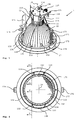
- the FIG. 1 1 illustrates a luminaire 1 according to the invention, namely a recessed luminaire for installation in a ceiling, with a holding body 17 having at least one circular opening with an opening edge 171.
- the luminaire 1 additionally comprises a stirrup 13 and a carrier 11.
- the carrier 11 comprises at least one holder 111 to hold at least one in FIG. 8
- the electric lamp 1111 and a reflector 15 are further illustrated.
- the carrier 11 further includes an elongated leg or carrier arm 112.
- the reflector 15 is held in the socket 111 by a spring 122.
- the opening has an opening center 19 and defines a rotation axis perpendicular to the opening plane through the opening center.
- the bracket 13 and the carrier 11 are rotatable together about the rotation axis.
- the carrier 11 is close to the opening edge 171 about a nearly vertical axis of rotation Swivel axis swiveling and / or tilting.
- the carrier 11 has a bracket 13 acting on the brake.
- the brake also points in FIG. 9 shown holding means 113,114,115,116, wherein the holding means in the mounted state engage the bracket 13.
- the holding means 113, 114, 115, 116 are held on a holding means 11b detachably mounted on the carrier.
- the slot-shaped opening of the hidden in the figure holding means 116 is shown simplified in dashed line.
- the holding means 11b forming plate and four away from this against the holding body 17 and - in a mounted on a ceiling light - against angled down and / or bent tabs each of which forms one of the retaining means 113, 114, 115, 116.
- the holding means 113, 114 or 115, 116 can also be connected inseparably to the carrier 11.
- the carrier 11 is preferably made of cast aluminum or heat and / or fire resistant plastic. The brake brakes pivoting of the carrier 11 about the pivot axis and holds the carrier 11 in different pivoting positions.
- the holding means 113,114,115,116 each have an opening, which consists in the illustrated embodiment of an extending from top to bottom slot or slot.
- the openings of the holding means 114,116 are referred to as first openings and have the distance a from each other.
- the openings of the holding means 113,115 are referred to as second openings and have the distance b from each other, wherein the distances a and b are measured from the center of the opening to the center of the opening.
- the bracket 13 has at least one bent leg and namely two curved legs 131,132, the main sections at least approximately form a circular arc about the pivot axis to the carrier is pivotable and / or tiltable.
- the leg 131 penetrates the openings of the holding means 113,114.
- the leg 132 penetrates the openings of the holding means 115,116.
- the two legs 131,132 are at their closer to the holding body ends by a cross member 138, which is shown here in a dashed line, connected to each other, which consists together with the legs of a wire.
- the distance between the legs in the region of the transverse element 138 and in FIG. 8 denoted by reference c may be greater, smaller or equal to the distance a or the distance b.
- these holding means 113,114,115,116 can slide along the two legs 131,132.
- the bracket 13 is preferably elastically deformable and resilient.
- Each opening in the holding means 113,114,115,116 is designed such that the guided leg of the bracket 13 has some play, but touches at least one point of the opening edge. Due to the elasticity of the bracket but at the same time a certain friction of the bracket is achieved in the edge region of the opening of the holding means. Thereby, a braking effect can be obtained, so that the lamp maintains in a given position.
- the distances a and b can be the same size, for example.
- the braking effect or the static friction and / or sliding friction between a leg of the bracket 13 and the edges of the openings of the retaining means 113,114,115,116 may possibly be strengthened or weakened by the distance a between the opening centers of the retaining means 114,116 being smaller or larger than the distance b of the corresponding holding means 113,115 is selected.
- the openings of the holding means according to the drawings instead of forming the openings of the holding means according to the drawings as longitudinal holes or slots, they could be designed as round holes.
- this can the braking effect to be influenced.
- the two legs 131, 132 of the bracket can, for example, run approximately parallel next to one another.
- the braking effect can also be enhanced or mitigated by the legs of the bracket are prefabricated so that they are not parallel to each other.
- the distance between the two legs 131, 132 may, for example, increase or decrease at least in places in a direction away from the transverse element 138.
- the carrier 11 has at least one as in FIG. 8 illustrated carrier-bearing shoe 118,119, wherein this is disposed on the socket 111 opposite the end of the support arm 112.
- the bracket 13 has at least one bracket bearing shoe 133,134.
- the embodiments shown in the figures show two carrier bearing shoes 118,119 and two strap bearing shoes 133,134.
- the carrier projection 1121 on the leg of the carrier 11 consists as in the embodiment shown of a part, but may also consist of several separated by interruptions projections.
- the or each carrier projection is located according to the drawings between the two carrier bearing shoes, but could also be in the same place as these.
- the or each support-bearing shoe 118,119 and the or each bracket-bearing shoe 133,134 surround the opening edge 171 such that they are rotatably mounted along the opening edge 171 around the opening center 19 around.
- the reference numerals 173 and 175 show on the holding body 17 held wings.
- the wings each include a clip or locking tabs 174 and 176 as a means of attachment, wherein in the assembly of the holding body 17 in the section in FIG. 3 shown building part 122 between the support surface 172 and the locking tabs 174 and 176 is clamped.
- FIG. 3 illustrates the luminaire mounted in the building part 122 Status.
- the building part 122 is shown in section and broken off.
- FIG. 2 illustrates a view of the lamp from below.
- the or each bracket bearing shoe is connected to a transverse element 138 of the bracket 13.
- the holding body 17 has a stop means 177 designed as a projection, nipple or lip.
- the nipples can be produced by embossing a metallic holding body 17.
- the at least one strap-bearing shoe 133,134 may be formed into a stop means 137.
- the stop means 137 of the bracket 13 is the stop means 177 of the holding body 17 such that they come into abutment with each other when the lamp is rotated on the holding means 17.
- FIG. 2 also illustrates the carrier bearing shoes 118,119 and the bracket bearing shoes 133,134.
- the holding nipple 152 hold the transparent plate 151 in the reflector 15.
- the transparent pane is preferably made of glass.
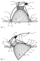
- FIG. 4 illustrates the inclined about the pivot axis lamp.
- the resilient bracket 13 preferably made of spring steel, is guided by the holding means 113,114, 115,116 such that the Light is braked in the selected inclination and does not dissolve by itself.
- the carrier bearing shoe 118,119 is preferably provided as a C-shaped hook with a hook tip 1181 and at least one projection held on the carrier and designed as a carrier projection or carrier nose 1121.
- the opening of the at least one carrier-bearing shoe is designed such that the carrier-bearing shoe in an angular range of ⁇ 1 to ⁇ 2 is pivotable about the opening edge 171.
- the at least one bracket-bearing shoe 133,134 is shaped so that it encloses the region of the opening edge 171 of the holding body 17 from both sides, as shown in FIG. 5 is apparent.
- FIG. 5 illustrates the holding body 17 shown as cut and broken off in the sectional view V according to FIG. 2
- the FIGS. 6 and 7 show the shown as cut and broken holding body 17 in the sectional view VI according to FIG. 2 ,
- FIG. 6 shows the cut carrier-bearing shoe 118, wherein the lamp is held perpendicular to the opening plane.
- FIG. 6 illustrates the carrier-bearing shoe 118 of the inclined lamp as a detail of the FIG. 4 ,
- FIG. 7 shows the carrier bearing shoe 118 in a detail view of FIG. 3 .
- An almost C-shaped hook tip 1181 of the carrier bearing shoe 118 and the carrier projection 1121 are guided around the opening edge 171 during the tilting process and / or unrolled.
- the carrier-bearing shoe 118 and the Carrier projection 1121 result in the side view of an almost closed eyelet. At least a portion of the inside of the bearing shoe 118 is in contact with the opening edge 171.
- the illustration applies to the support bearing shoe 119th
- FIG. 8 illustrates the inventive lamp without the reflector 15, but essentially with the one support arm 112 and a socket 111 having carrier 11 and bracket 13.
- the support bearing shoe 118,119 is preferably a c-shaped hook or gripper with a hook tip 1181,1191st and at least one projection held on the carrier and formed as a carrier projection or carrier nose 1121.
- the carrier projection 1121 is shown partially broken away here, so that the carrier bearing shoe 119 can be seen.
- the holding means designated by reference numeral 11b comprises the holding means 113,114, 115,116 and is preferably made of sheet steel. It is, for example, connected by screws, rivets or pressing with the carrier 11.
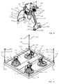
- FIG. 9 illustrates an embodiment of the inventive lamp.
- the holding body 17 has, for example, a square base area and essentially has at least two openings, each with corresponding opening edges 171.
- the holding body 17 may comprise mounting means 178, 180 and / or cable 179, so that the holding body can, for example, be mounted on a room ceiling and the light can be hung, for example, as a pendant light on the ceiling.
- the holding body 17 may in this embodiment have an electrical distributor 181, so that a central supply allows efficient installation of the lights.
- FIG. 9 also illustrates the holding means 113,114,115,116 on the mounted differently rotated and tilted lights.
Landscapes
- Engineering & Computer Science (AREA)
- General Engineering & Computer Science (AREA)
- Fastening Of Light Sources Or Lamp Holders (AREA)
- Non-Portable Lighting Devices Or Systems Thereof (AREA)
Claims (17)
- Luminaire (1), comportant un corps de retenue (17) présentant au moins une ouverture circulaire, un arceau (13) et un support (11) qui comprend au moins une douille (111) pour maintenir au moins une ampoule électrique, l'ouverture comprenant une marge d'ouverture (171) ainsi qu'un centre d'ouverture (19) et définissant un axe de rotation perpendiculaire au plan de l'ouverture et passant par le centre d'ouverture (19), caractérisé en ce que- le support (11) comprend au moins un patin d'appui de support (118, 119) ;- l'arceau (13) comprend au moins un patin d'appui d'arceau (133, 134) ; et- le ou les patins d'appui de support (118, 119) et le ou les patins d'appui d'arceau (133, 134) sont engagés autour de la marge d'ouverture (171) de telle manière qu'ils peuvent coulisser le long de la marge d'ouverture (171) et peuvent tourner ensemble autour de l'axe de rotation.
- Luminaire (1) selon la revendication 1, caractérisé en ce que le ou les patins d'appui de support (118, 119) du support (11) sont aptes à coulisser sur la marge d'ouverture (171) si bien qu'ils sont aptes à basculer de manière au moins approximative autour d'un axe de basculement perpendiculaire à l'axe de rotation.
- Luminaire (1) selon une ou plusieurs des revendications précédentes, caractérisé en ce que le support (11) comprend des moyens de retenue (113, 114 ; 115, 116) pour retenir l'arceau (13), pour freiner des basculements du support (11) autour de l'axe de basculement et pour immobiliser le support (11) dans différentes positions de basculement.
- Luminaire (1) selon une ou plusieurs des revendications précédentes, caractérisé en ce que l'arceau (13) est configuré au moins par endroits comme un élément élastique ou un ressort et, de préférence, est réalisé à l'aide d'un fil d'acier à ressort courbé.
- Luminaire (1) selon une ou plusieurs des revendications précédentes, caractérisé en ce que l'arceau (13) comprend au moins une branche élastique (131, 132), au moins partiellement courbée, qui traverse au moins deux ouvertures des moyens de retenue (113, 114 ; 115, 116) écartées l'une de l'autre, par exemple en forme de fente, si bien que les moyens de retenue, lorsqu'ils coulissent, sont retenus par l'effet du frottement sur la ou les branches (131, 132) de l'arceau (13).
- Luminaire (1) selon la revendication 5, caractérisé en ce que :- le ou les patins d'appui d'arceau (133, 134) sont implantés à une extrémité de la branche (131, 132) ou de l'une de celles-ci ; et- la ou les branches (131, 132), à l'extrémité opposée à un patin d'appui d'arceau (133, 134), possèdent un élément final (135, 136) en forme de crochet et/ou d'oeillet, qui sert de butée.
- Luminaire (1) selon l'une des revendications 5 ou 6, caractérisé en ce que l'arceau (13) possède deux branches (131, 132) juxtaposées à une certaine distance l'une de l'autre et un élément transversal (138) qui les relie entre elles par l'une de leurs extrémités, ainsi que deux patins d'appui d'arceau (133, 134) qui sont formés par l'une des extrémités des branches (131, 132) et/ou par l'élément transversal (138).
- Luminaire (1) selon la revendication 7, caractérisé en ce que :- chacune des deux branches (131, 132) traverse une première ouverture et une deuxième ouverture des moyens de retenue (113, 114 ; 115, 116) ;- les deux premières ouvertures sont à une distance a l'une de l'autre ; et- les deux deuxièmes ouvertures sont à une distance b l'une de l'autre.
- Luminaire (1) selon la revendication 8, caractérisé en ce que la distance a est inférieure ou supérieure à la distance b.
- Luminaire (1) selon la revendication 8, caractérisé en ce que la distance a est égale à la distance b.
- Luminaire (1) selon une ou plusieurs des revendications 7 à 10, caractérisé en ce que la distance des deux branches (131, 132) varie au moins par endroits dans la direction s'éloignant de l'élément transversal (138).
- Luminaire (1) selon une ou plusieurs des revendications 7 à 10, caractérisé en ce que les deux branches (131, 132) sont au moins approximativement parallèles entre elles.
- Luminaire (1) selon une ou plusieurs des revendications précédentes, caractérisé en ce que le corps de retenue (17) comprend des moyens de fixation (173, 174, 178, 179) pour le montage du corps de retenue (17) sur un élément de construction.
- Luminaire (1) selon une ou plusieurs des revendications précédentes, caractérisé en ce que l'arceau (13) possède des butées (137) et le corps de retenue (17) possède au moins une butée (177) afin de limiter l'angle de rotation autour de l'axe de rotation.
- Luminaire (1) selon une ou plusieurs des revendications précédentes, caractérisé en ce que :- le ou les patins d'appui de support (118, 119) possèdent une partie en forme de crochet ; et- le ou les patins d'appui d'arceau (133, 134) possèdent une partie en forme de crochet.
- Luminaire (1) selon la revendication 2 et la revendication 15, caractérisé en ce que le support (11) possède au moins une saillie de support (1121) qui, dans une direction d'observation parallèle à l'axe de basculement du patin d'appui de support (118, 119), forme avec la partie en forme de crochet du ou des patins d'appui de support (118, 119) un oeillet au moins approximativement fermé.
- Procédé de montage d'un luminaire selon une ou plusieurs des revendications précédentes, caractérisé en ce que :- la ou les branches (131, 132) de l'arceau (13) sont maintenues de manière coulissante sur les moyens de retenue (113, 114 ; 115, 116) du support (11) ;- pour assembler le support (11) et l'arceau (13) sur le corps de retenue (17) du luminaire, les patins d'appui de support (118, 119) et les patins d'appui d'arceau (133, 134) sont montés de part et d'autre de la marge d'ouverture (171) du corps de retenue (17) et sont maintenus par la tension de l'arceau (13), la ou les branches (131, 132) de l'arceau (13) étant immobilisées par les moyens de retenue (113, 114 ; 115, 116) jouant le rôle de frein pour éviter qu'elles ne basculent et/ou ne tournent d'elles-mêmes.
Applications Claiming Priority (1)
| Application Number | Priority Date | Filing Date | Title |
|---|---|---|---|
| CH01091/08A CH699116A1 (de) | 2008-07-14 | 2008-07-14 | Leuchte. |
Publications (3)
| Publication Number | Publication Date |
|---|---|
| EP2146140A2 EP2146140A2 (fr) | 2010-01-20 |
| EP2146140A3 EP2146140A3 (fr) | 2011-07-20 |
| EP2146140B1 true EP2146140B1 (fr) | 2012-08-08 |
Family
ID=40020244
Family Applications (1)
| Application Number | Title | Priority Date | Filing Date |
|---|---|---|---|
| EP20090164890 Not-in-force EP2146140B1 (fr) | 2008-07-14 | 2009-07-08 | Dispositif d'éclairage réglable |
Country Status (2)
| Country | Link |
|---|---|
| EP (1) | EP2146140B1 (fr) |
| CH (1) | CH699116A1 (fr) |
Families Citing this family (1)
| Publication number | Priority date | Publication date | Assignee | Title |
|---|---|---|---|---|
| WO2019204944A1 (fr) * | 2018-04-27 | 2019-10-31 | Fluxwerx Illumination Inc. | Ensembles, systèmes et procédés de suspension équilibrée de luminaires |
Family Cites Families (4)
| Publication number | Priority date | Publication date | Assignee | Title |
|---|---|---|---|---|
| FR2729742A1 (fr) * | 1995-01-24 | 1996-07-26 | Epi D Or Diffusion | Dispositif de montage de spot dans un faux-plafond ou un faux-mur |
| US6554457B1 (en) * | 2000-09-28 | 2003-04-29 | Juno Lighting, Inc. | System for lamp retention and relamping in an adjustable trim lighting fixture |
| CA2550685A1 (fr) * | 2006-06-19 | 2007-12-19 | Yen-Chang Chen | Appareil d'eclairage encastre |
| DE202008000857U1 (de) * | 2008-01-22 | 2008-03-20 | Trilux Gmbh & Co. Kg | Schwenkbare Einbauleuchte |
-
2008
- 2008-07-14 CH CH01091/08A patent/CH699116A1/de not_active Application Discontinuation
-
2009
- 2009-07-08 EP EP20090164890 patent/EP2146140B1/fr not_active Not-in-force
Also Published As
| Publication number | Publication date |
|---|---|
| EP2146140A3 (fr) | 2011-07-20 |
| CH699116A1 (de) | 2010-01-15 |
| EP2146140A2 (fr) | 2010-01-20 |
Similar Documents
| Publication | Publication Date | Title |
|---|---|---|
| EP0732540A2 (fr) | Armature lumineuse encastrée avec des moyens pour sa fixation dans le corps de logement | |
| DE202013104140U1 (de) | Einbauleuchte | |
| EP3209933B1 (fr) | Plafonnier à spots lumineux | |
| EP2250434B2 (fr) | Dispositif de montage pour lampe encastrée ou montée en saillie au plafond | |
| EP2146140B1 (fr) | Dispositif d'éclairage réglable | |
| DE202012104544U1 (de) | Deckeneinbauleuchte | |
| EP2166280B1 (fr) | Lampe dotée d'un support magnétique pour la suspension d'un élément de montage sur un boîtier de lampes | |
| EP2616737B1 (fr) | Dispositif de montage pour spot | |
| EP1085257B1 (fr) | Projecteur d'éclairage avec verrouillage de l'articulation | |
| EP3209934B1 (fr) | Plafonnier à spots lumineux | |
| EP2602542B1 (fr) | Dispositif d'éclairage | |
| DE19954735B4 (de) | Leuchte für den Einbau in eine Öffnung in einer Einbaufläche | |
| EP2365245A1 (fr) | Réflecteur | |
| EP2107298B1 (fr) | Lampe suspendue allongée | |
| EP0912860B1 (fr) | Luminaire encastre comportant des moyens de retenue pour sa fixation dans un corps de fixation, ou moyens de retenue pour un tel luminaire | |
| EP0892211B1 (fr) | Lampe à encastrer | |
| EP2208192B1 (fr) | Appareil d'éclairage pour pictogramme | |
| DE202018101307U1 (de) | Seilleuchte für eine Straßenbeleuchtung | |
| DE1497267A1 (de) | Einbauleuchte fuer Decken,Waende od.dgl.,insbesondere fuer Schaufenster | |
| EP3070397B1 (fr) | Support de monture reglable pour une lampe reflechissante et lampe reflechissante | |
| AT513703B1 (de) | Deckeneinbauleuchte | |
| DE19942793A1 (de) | Schwenkbare Leuchtenhalterung | |
| DE7522285U (de) | Einrichtung zur lösbaren Verbindung zweier Bauteile | |
| EP3056798B1 (fr) | Élement d'installation, de preference lampe encastree | |
| EP0166942B1 (fr) | Profilé mural pour support de lampe |
Legal Events
| Date | Code | Title | Description |
|---|---|---|---|
| PUAI | Public reference made under article 153(3) epc to a published international application that has entered the european phase |
Free format text: ORIGINAL CODE: 0009012 |
|
| AK | Designated contracting states |
Kind code of ref document: A2 Designated state(s): AT BE BG CH CY CZ DE DK EE ES FI FR GB GR HR HU IE IS IT LI LT LU LV MC MK MT NL NO PL PT RO SE SI SK SM TR |
|
| PUAL | Search report despatched |
Free format text: ORIGINAL CODE: 0009013 |
|
| AK | Designated contracting states |
Kind code of ref document: A3 Designated state(s): AT BE BG CH CY CZ DE DK EE ES FI FR GB GR HR HU IE IS IT LI LT LU LV MC MK MT NL NO PL PT RO SE SI SK SM TR |
|
| GRAP | Despatch of communication of intention to grant a patent |
Free format text: ORIGINAL CODE: EPIDOSNIGR1 |
|
| 17P | Request for examination filed |
Effective date: 20120120 |
|
| GRAS | Grant fee paid |
Free format text: ORIGINAL CODE: EPIDOSNIGR3 |
|
| GRAA | (expected) grant |
Free format text: ORIGINAL CODE: 0009210 |
|
| AK | Designated contracting states |
Kind code of ref document: B1 Designated state(s): AT BE BG CH CY CZ DE DK EE ES FI FR GB GR HR HU IE IS IT LI LT LU LV MC MK MT NL NO PL PT RO SE SI SK SM TR |
|
| REG | Reference to a national code |
Ref country code: GB Ref legal event code: FG4D Free format text: NOT ENGLISH |
|
| REG | Reference to a national code |
Ref country code: AT Ref legal event code: REF Ref document number: 569974 Country of ref document: AT Kind code of ref document: T Effective date: 20120815 Ref country code: CH Ref legal event code: EP |
|
| REG | Reference to a national code |
Ref country code: IE Ref legal event code: FG4D Free format text: LANGUAGE OF EP DOCUMENT: GERMAN |
|
| REG | Reference to a national code |
Ref country code: DE Ref legal event code: R096 Ref document number: 502009004306 Country of ref document: DE Effective date: 20121004 |
|
| REG | Reference to a national code |
Ref country code: CH Ref legal event code: NV Representative=s name: BRAUNPAT BRAUN EDER AG |
|
| REG | Reference to a national code |
Ref country code: NL Ref legal event code: VDEP Effective date: 20120808 |
|
| REG | Reference to a national code |
Ref country code: LT Ref legal event code: MG4D Effective date: 20120808 |
|
| PG25 | Lapsed in a contracting state [announced via postgrant information from national office to epo] |
Ref country code: IS Free format text: LAPSE BECAUSE OF FAILURE TO SUBMIT A TRANSLATION OF THE DESCRIPTION OR TO PAY THE FEE WITHIN THE PRESCRIBED TIME-LIMIT Effective date: 20121208 Ref country code: CY Free format text: LAPSE BECAUSE OF FAILURE TO SUBMIT A TRANSLATION OF THE DESCRIPTION OR TO PAY THE FEE WITHIN THE PRESCRIBED TIME-LIMIT Effective date: 20120808 Ref country code: FI Free format text: LAPSE BECAUSE OF FAILURE TO SUBMIT A TRANSLATION OF THE DESCRIPTION OR TO PAY THE FEE WITHIN THE PRESCRIBED TIME-LIMIT Effective date: 20120808 Ref country code: HR Free format text: LAPSE BECAUSE OF FAILURE TO SUBMIT A TRANSLATION OF THE DESCRIPTION OR TO PAY THE FEE WITHIN THE PRESCRIBED TIME-LIMIT Effective date: 20120808 Ref country code: NO Free format text: LAPSE BECAUSE OF FAILURE TO SUBMIT A TRANSLATION OF THE DESCRIPTION OR TO PAY THE FEE WITHIN THE PRESCRIBED TIME-LIMIT Effective date: 20121108 Ref country code: LT Free format text: LAPSE BECAUSE OF FAILURE TO SUBMIT A TRANSLATION OF THE DESCRIPTION OR TO PAY THE FEE WITHIN THE PRESCRIBED TIME-LIMIT Effective date: 20120808 |
|
| PG25 | Lapsed in a contracting state [announced via postgrant information from national office to epo] |
Ref country code: SE Free format text: LAPSE BECAUSE OF FAILURE TO SUBMIT A TRANSLATION OF THE DESCRIPTION OR TO PAY THE FEE WITHIN THE PRESCRIBED TIME-LIMIT Effective date: 20120808 Ref country code: LV Free format text: LAPSE BECAUSE OF FAILURE TO SUBMIT A TRANSLATION OF THE DESCRIPTION OR TO PAY THE FEE WITHIN THE PRESCRIBED TIME-LIMIT Effective date: 20120808 Ref country code: PL Free format text: LAPSE BECAUSE OF FAILURE TO SUBMIT A TRANSLATION OF THE DESCRIPTION OR TO PAY THE FEE WITHIN THE PRESCRIBED TIME-LIMIT Effective date: 20120808 Ref country code: PT Free format text: LAPSE BECAUSE OF FAILURE TO SUBMIT A TRANSLATION OF THE DESCRIPTION OR TO PAY THE FEE WITHIN THE PRESCRIBED TIME-LIMIT Effective date: 20121210 Ref country code: GR Free format text: LAPSE BECAUSE OF FAILURE TO SUBMIT A TRANSLATION OF THE DESCRIPTION OR TO PAY THE FEE WITHIN THE PRESCRIBED TIME-LIMIT Effective date: 20121109 Ref country code: SI Free format text: LAPSE BECAUSE OF FAILURE TO SUBMIT A TRANSLATION OF THE DESCRIPTION OR TO PAY THE FEE WITHIN THE PRESCRIBED TIME-LIMIT Effective date: 20120808 |
|
| PG25 | Lapsed in a contracting state [announced via postgrant information from national office to epo] |
Ref country code: NL Free format text: LAPSE BECAUSE OF FAILURE TO SUBMIT A TRANSLATION OF THE DESCRIPTION OR TO PAY THE FEE WITHIN THE PRESCRIBED TIME-LIMIT Effective date: 20120808 |
|
| PG25 | Lapsed in a contracting state [announced via postgrant information from national office to epo] |
Ref country code: EE Free format text: LAPSE BECAUSE OF FAILURE TO SUBMIT A TRANSLATION OF THE DESCRIPTION OR TO PAY THE FEE WITHIN THE PRESCRIBED TIME-LIMIT Effective date: 20120808 Ref country code: ES Free format text: LAPSE BECAUSE OF FAILURE TO SUBMIT A TRANSLATION OF THE DESCRIPTION OR TO PAY THE FEE WITHIN THE PRESCRIBED TIME-LIMIT Effective date: 20121119 Ref country code: RO Free format text: LAPSE BECAUSE OF FAILURE TO SUBMIT A TRANSLATION OF THE DESCRIPTION OR TO PAY THE FEE WITHIN THE PRESCRIBED TIME-LIMIT Effective date: 20120808 Ref country code: DK Free format text: LAPSE BECAUSE OF FAILURE TO SUBMIT A TRANSLATION OF THE DESCRIPTION OR TO PAY THE FEE WITHIN THE PRESCRIBED TIME-LIMIT Effective date: 20120808 Ref country code: CZ Free format text: LAPSE BECAUSE OF FAILURE TO SUBMIT A TRANSLATION OF THE DESCRIPTION OR TO PAY THE FEE WITHIN THE PRESCRIBED TIME-LIMIT Effective date: 20120808 |
|
| PG25 | Lapsed in a contracting state [announced via postgrant information from national office to epo] |
Ref country code: SK Free format text: LAPSE BECAUSE OF FAILURE TO SUBMIT A TRANSLATION OF THE DESCRIPTION OR TO PAY THE FEE WITHIN THE PRESCRIBED TIME-LIMIT Effective date: 20120808 Ref country code: IT Free format text: LAPSE BECAUSE OF FAILURE TO SUBMIT A TRANSLATION OF THE DESCRIPTION OR TO PAY THE FEE WITHIN THE PRESCRIBED TIME-LIMIT Effective date: 20120808 |
|
| PLBE | No opposition filed within time limit |
Free format text: ORIGINAL CODE: 0009261 |
|
| STAA | Information on the status of an ep patent application or granted ep patent |
Free format text: STATUS: NO OPPOSITION FILED WITHIN TIME LIMIT |
|
| 26N | No opposition filed |
Effective date: 20130510 |
|
| PG25 | Lapsed in a contracting state [announced via postgrant information from national office to epo] |
Ref country code: BG Free format text: LAPSE BECAUSE OF FAILURE TO SUBMIT A TRANSLATION OF THE DESCRIPTION OR TO PAY THE FEE WITHIN THE PRESCRIBED TIME-LIMIT Effective date: 20121108 |
|
| REG | Reference to a national code |
Ref country code: DE Ref legal event code: R097 Ref document number: 502009004306 Country of ref document: DE Effective date: 20130510 |
|
| BERE | Be: lapsed |
Owner name: REGENT BELEUCHTUNGSKORPER A.G. Effective date: 20130731 |
|
| PG25 | Lapsed in a contracting state [announced via postgrant information from national office to epo] |
Ref country code: MC Free format text: LAPSE BECAUSE OF FAILURE TO SUBMIT A TRANSLATION OF THE DESCRIPTION OR TO PAY THE FEE WITHIN THE PRESCRIBED TIME-LIMIT Effective date: 20120808 |
|
| GBPC | Gb: european patent ceased through non-payment of renewal fee |
Effective date: 20130708 |
|
| REG | Reference to a national code |
Ref country code: IE Ref legal event code: MM4A |
|
| REG | Reference to a national code |
Ref country code: FR Ref legal event code: ST Effective date: 20140331 |
|
| PG25 | Lapsed in a contracting state [announced via postgrant information from national office to epo] |
Ref country code: GB Free format text: LAPSE BECAUSE OF NON-PAYMENT OF DUE FEES Effective date: 20130708 Ref country code: BE Free format text: LAPSE BECAUSE OF NON-PAYMENT OF DUE FEES Effective date: 20130731 |
|
| PG25 | Lapsed in a contracting state [announced via postgrant information from national office to epo] |
Ref country code: FR Free format text: LAPSE BECAUSE OF NON-PAYMENT OF DUE FEES Effective date: 20130731 |
|
| PG25 | Lapsed in a contracting state [announced via postgrant information from national office to epo] |
Ref country code: IE Free format text: LAPSE BECAUSE OF NON-PAYMENT OF DUE FEES Effective date: 20130708 |
|
| PG25 | Lapsed in a contracting state [announced via postgrant information from national office to epo] |
Ref country code: SM Free format text: LAPSE BECAUSE OF FAILURE TO SUBMIT A TRANSLATION OF THE DESCRIPTION OR TO PAY THE FEE WITHIN THE PRESCRIBED TIME-LIMIT Effective date: 20120808 |
|
| PG25 | Lapsed in a contracting state [announced via postgrant information from national office to epo] |
Ref country code: TR Free format text: LAPSE BECAUSE OF FAILURE TO SUBMIT A TRANSLATION OF THE DESCRIPTION OR TO PAY THE FEE WITHIN THE PRESCRIBED TIME-LIMIT Effective date: 20120808 Ref country code: MT Free format text: LAPSE BECAUSE OF FAILURE TO SUBMIT A TRANSLATION OF THE DESCRIPTION OR TO PAY THE FEE WITHIN THE PRESCRIBED TIME-LIMIT Effective date: 20120808 |
|
| PG25 | Lapsed in a contracting state [announced via postgrant information from national office to epo] |
Ref country code: LU Free format text: LAPSE BECAUSE OF NON-PAYMENT OF DUE FEES Effective date: 20130708 Ref country code: HU Free format text: LAPSE BECAUSE OF FAILURE TO SUBMIT A TRANSLATION OF THE DESCRIPTION OR TO PAY THE FEE WITHIN THE PRESCRIBED TIME-LIMIT; INVALID AB INITIO Effective date: 20090708 Ref country code: MK Free format text: LAPSE BECAUSE OF FAILURE TO SUBMIT A TRANSLATION OF THE DESCRIPTION OR TO PAY THE FEE WITHIN THE PRESCRIBED TIME-LIMIT Effective date: 20120808 |
|
| PGFP | Annual fee paid to national office [announced via postgrant information from national office to epo] |
Ref country code: CH Payment date: 20160802 Year of fee payment: 8 Ref country code: DE Payment date: 20160705 Year of fee payment: 8 |
|
| PGFP | Annual fee paid to national office [announced via postgrant information from national office to epo] |
Ref country code: AT Payment date: 20160630 Year of fee payment: 8 |
|
| REG | Reference to a national code |
Ref country code: DE Ref legal event code: R119 Ref document number: 502009004306 Country of ref document: DE |
|
| REG | Reference to a national code |
Ref country code: CH Ref legal event code: PL |
|
| REG | Reference to a national code |
Ref country code: AT Ref legal event code: MM01 Ref document number: 569974 Country of ref document: AT Kind code of ref document: T Effective date: 20170708 |
|
| PG25 | Lapsed in a contracting state [announced via postgrant information from national office to epo] |
Ref country code: DE Free format text: LAPSE BECAUSE OF NON-PAYMENT OF DUE FEES Effective date: 20180201 Ref country code: LI Free format text: LAPSE BECAUSE OF NON-PAYMENT OF DUE FEES Effective date: 20170731 Ref country code: CH Free format text: LAPSE BECAUSE OF NON-PAYMENT OF DUE FEES Effective date: 20170731 |
|
| PG25 | Lapsed in a contracting state [announced via postgrant information from national office to epo] |
Ref country code: AT Free format text: LAPSE BECAUSE OF NON-PAYMENT OF DUE FEES Effective date: 20170708 |
|
| P01 | Opt-out of the competence of the unified patent court (upc) registered |
Effective date: 20230714 |