EP2146129A2 - Rohrauskleidungsmaterial und Verfahren zu dessen Herstellung - Google Patents
Rohrauskleidungsmaterial und Verfahren zu dessen Herstellung Download PDFInfo
- Publication number
- EP2146129A2 EP2146129A2 EP09163415A EP09163415A EP2146129A2 EP 2146129 A2 EP2146129 A2 EP 2146129A2 EP 09163415 A EP09163415 A EP 09163415A EP 09163415 A EP09163415 A EP 09163415A EP 2146129 A2 EP2146129 A2 EP 2146129A2
- Authority
- EP
- European Patent Office
- Prior art keywords
- lining material
- resin
- pipe
- absorbent
- absorbent material
- Prior art date
- Legal status (The legal status is an assumption and is not a legal conclusion. Google has not performed a legal analysis and makes no representation as to the accuracy of the status listed.)
- Withdrawn
Links
Images


Classifications
-
- B—PERFORMING OPERATIONS; TRANSPORTING
- B29—WORKING OF PLASTICS; WORKING OF SUBSTANCES IN A PLASTIC STATE IN GENERAL
- B29C—SHAPING OR JOINING OF PLASTICS; SHAPING OF MATERIAL IN A PLASTIC STATE, NOT OTHERWISE PROVIDED FOR; AFTER-TREATMENT OF THE SHAPED PRODUCTS, e.g. REPAIRING
- B29C63/00—Lining or sheathing, i.e. applying preformed layers or sheathings of plastics; Apparatus therefor
- B29C63/26—Lining or sheathing of internal surfaces
- B29C63/34—Lining or sheathing of internal surfaces using tubular layers or sheathings
-
- F—MECHANICAL ENGINEERING; LIGHTING; HEATING; WEAPONS; BLASTING
- F16—ENGINEERING ELEMENTS AND UNITS; GENERAL MEASURES FOR PRODUCING AND MAINTAINING EFFECTIVE FUNCTIONING OF MACHINES OR INSTALLATIONS; THERMAL INSULATION IN GENERAL
- F16L—PIPES; JOINTS OR FITTINGS FOR PIPES; SUPPORTS FOR PIPES, CABLES OR PROTECTIVE TUBING; MEANS FOR THERMAL INSULATION IN GENERAL
- F16L55/00—Devices or appurtenances for use in, or in connection with, pipes or pipe systems
- F16L55/16—Devices for covering leaks in pipes or hoses, e.g. hose-menders
- F16L55/162—Devices for covering leaks in pipes or hoses, e.g. hose-menders from inside the pipe
- F16L55/165—Devices for covering leaks in pipes or hoses, e.g. hose-menders from inside the pipe a pipe or flexible liner being inserted in the damaged section
- F16L55/1656—Devices for covering leaks in pipes or hoses, e.g. hose-menders from inside the pipe a pipe or flexible liner being inserted in the damaged section materials for flexible liners
-
- B—PERFORMING OPERATIONS; TRANSPORTING
- B29—WORKING OF PLASTICS; WORKING OF SUBSTANCES IN A PLASTIC STATE IN GENERAL
- B29C—SHAPING OR JOINING OF PLASTICS; SHAPING OF MATERIAL IN A PLASTIC STATE, NOT OTHERWISE PROVIDED FOR; AFTER-TREATMENT OF THE SHAPED PRODUCTS, e.g. REPAIRING
- B29C63/00—Lining or sheathing, i.e. applying preformed layers or sheathings of plastics; Apparatus therefor
- B29C63/26—Lining or sheathing of internal surfaces
-
- F—MECHANICAL ENGINEERING; LIGHTING; HEATING; WEAPONS; BLASTING
- F16—ENGINEERING ELEMENTS AND UNITS; GENERAL MEASURES FOR PRODUCING AND MAINTAINING EFFECTIVE FUNCTIONING OF MACHINES OR INSTALLATIONS; THERMAL INSULATION IN GENERAL
- F16L—PIPES; JOINTS OR FITTINGS FOR PIPES; SUPPORTS FOR PIPES, CABLES OR PROTECTIVE TUBING; MEANS FOR THERMAL INSULATION IN GENERAL
- F16L55/00—Devices or appurtenances for use in, or in connection with, pipes or pipe systems
- F16L55/16—Devices for covering leaks in pipes or hoses, e.g. hose-menders
- F16L55/162—Devices for covering leaks in pipes or hoses, e.g. hose-menders from inside the pipe
- F16L55/165—Devices for covering leaks in pipes or hoses, e.g. hose-menders from inside the pipe a pipe or flexible liner being inserted in the damaged section
- F16L55/1652—Devices for covering leaks in pipes or hoses, e.g. hose-menders from inside the pipe a pipe or flexible liner being inserted in the damaged section the flexible liner being pulled into the damaged section
- F16L55/1654—Devices for covering leaks in pipes or hoses, e.g. hose-menders from inside the pipe a pipe or flexible liner being inserted in the damaged section the flexible liner being pulled into the damaged section and being inflated
Definitions
- the present invention relates to a pipe lining material comprising a flexible, tubular resin-absorbent material impregnated with a curable liquid resin, and to a method for manufacturing the pipe lining material.
- Pipe lining methods for lining and repairing sewer pipes or other conduits without having to dig the conduit out of the ground have been used in cases where the conduit has deteriorated.
- a pipe lining material is everted or pulled into a conduit using fluid pressure.
- the pipe lining material comprises a tubular resin-absorbent material having an exterior surface covered by a plastic film, the material being impregnated with an uncured curable liquid resin.
- the pipe lining material is held pressed against the inner wall of the conduit, and the curable resin impregnated in the pipe lining material is cured to line the inner wall of the conduit.
- a photo-curing resin or a thermosetting resin is used for the curable resin with which the tubular resin-absorbent material is impregnated.
- the resin is cured by maneuvering an irradiation device (a UV lamp, a visible-light source, or another light irradiation source) into the pipe lining material which is kept pressed against the inner wall of the conduit and held in a circular shape.
- an irradiation device a UV lamp, a visible-light source, or another light irradiation source
- hot water, hot air, or another heat medium is applied to the pipe lining material to cure the resin.
- a tubular resin-absorbent material be impregnated by both a photo-curing resin and a thermosetting resin, so that curing can be accomplished in a relatively short time, even if the pipe lining material is thick (see Japanese Laid-open Patent Application Publication No. 2003-33970 ).
- the photo-curing resin of such a pipe lining material will be on the interior side. First the inside resin is cured by being exposed to light, and the other resin is cured by the heat generated when the interior-side resin is cured.
- the heat generated as a result of the curing of the photo-curing resin is of high temperature, so that the other resin can cure rapidly by generated heat.
- the rapid curing leads to problems in that voids (gaps) form in the cured pipe lining material, water-tightness deteriorates, and water may seep in from the ground even after the pipeline has been lined.
- a problem is also presented in that, after having cured, the finished lining is of poor quality.
- a pipe lining material for insertion into a pipe to rehabilitate an inner peripheral surface thereof comprises an outer lining material made of a tubular resin-absorbent material impregnated with a curable liquid resin, and an inner lining material which comes into close contact with an inner peripheral surface of the outer lining material and which is made of a tubular resin-absorbent material impregnated with a curable liquid resin.
- the resin-absorbent material of the inner lining material has a higher density than that of the outer lining material.
- the present invention provides a method for manufacturing a pipe lining material that is inserted into a pipe to rehabilitate an inner peripheral surface thereof.
- Prepared in the method are an outer lining material made of a tubular resin-absorbent material that is impregnated with a curable liquid resin, and an inner lining material made of a tubular resin-absorbent material that is impregnated with a curable liquid resin.
- the resin-absorbent material of the inner lining material has a higher density than the resin-absorbent material of the outer lining material.
- the inner lining material is inserted into the outer lining material so as to be in close contact therewith to manufacture a pipe lining material having the outer lining material and the inner lining material.
- an inner lining material that is made of a tubular resin-absorbent material impregnated with a curable liquid resin is disposed as a layer inside an outer lining material made of a tubular resin-absorbent material impregnated with a curable liquid resin.
- the resin-absorbent material of the inner lining material has a higher density than the resin-absorbent material of the outer lining material. Since the density of the resin-absorbent material of the inner lining material is higher than the density of the resin-absorbent material of the outer lining material, voids are less readily formed, and the surface becomes smooth and airtight.
- the same effect will be obtained for cases where the resin-absorbent materials of the inner and outer lining materials are both impregnated with a photo-cursing resin and a thermosetting resin; where the resin-absorbent materials of the inner and outer lining materials are impregnated with only a photo-curing resin or with only a thermosetting resin, or where one of the resin-absorbent materials is impregnated with a photo-curing resin or a thermosetting resin and the other resin-absorbent material is impregnated with both a photo-curing resin and a thermosetting resin.
- a sewer main pipe is shown as a pipe to be rehabilitated.
- the present invention can also be applied to cases in which pipes used in a water supply system, agricultural irrigation system, and the like will be lined.
- first resin a resin that cures by light
- second resin a thermosetting resin or an ambient-temperature-curing resin that cures by heat
- the present invention can also be applied to a case in which the resin-absorbent material of either the inner or outer lining material is impregnated with the first or second resin, and the resin-absorbent material of the other lining material is impregnated with both the first and second resins.
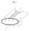
- FIGS. 1 to 3 show one embodiment of a pipe lining material according to the present invention.
- the pipe lining material 1 has a two-layer structure comprising an outer lining material (outer liner) 10 and an inner lining material (inner liner) 11.
- the outer lining material 10 is made of a nonwoven, flexible, tubular resin-absorbent material 10a, an outer peripheral surface thereof being coated with an airtight plastic film 10b.
- the resin-absorbent material 10a is impregnated with the first resin and the second resin, which are in the state of an uncured liquid.
- the nonwoven resin-absorbent material 10a is made of fibers of plastics such as polyester, polypropylene, nylon, acrylic, vinylon, or the like; glass fibers; and the like.
- the liquid-form second resin with which the resin-absorbent material 10a is impregnated is an unsaturated polyester resin, epoxy resin, vinyl ester resin, or the like to which a thermal catalyst has been added.
- the liquid-form first resin with which the resin-absorbent material 10a is impregnated is the same resin as the second resin, but a photocatalyst is added in place of a thermal catalyst.
- the first resin and the second resin are thus the same except the catalyst added, and are both thermosetting resins; however, the second resin having a thermal catalyst added thereto may be called a thermosetting resin, and the first resin having a photocatalyst added thereto a photo-curing resin.
- Polyethylene polyethylene/nylon copolymer, vinyl chloride, polypropylene, or the like is used for the airtight plastic film 10b.
- the resin-absorbent material 10a of the outer lining material 10 is impregnated with the first and second resins that are in a mixed state.
- the resins can also be impregnated in a distributed fashion, with the inner peripheral surface being impregnated with the first resin and the outer peripheral surface being impregnated with the second resin.
- Two-layer impregnation is also possible, a layer of the first resin being formed on the inner peripheral surface and a layer of the second resin being formed on the outer peripheral surface.
- the terms “inner peripheral surface” and “outer peripheral surface” express the relationship between the inside and the outside of a pipe lining material that has been inserted into an existing pipe and prepared for exposure to light. Accordingly, in a case in which the lining material is to be inserted into an existing pipe using eversion, the lining material, before being inserted, will be in a state in which the first resin is distributed or present in the outer peripheral surface thereof, and the second resin is distributed or present in the inner peripheral surface thereof.
- the resin-absorbent material 10a of the outer lining material 10 is a material of prescribed width and length, which has been coated on one side with a high-airtightness plastic film 10b.
- the flat resin-absorbent material is formed into a cylindrical shape, the two ends thereof are aligned and stitched together, and the resin-absorbent material 10a is formed in a tubular shape as shown in the upper part of FIG. 2 .
- a polyurethane, polyethylene, or polypropylene tape 14 is affixed to the resin-absorbent material 10a, whereby a region 10c where the two ends of the resin-absorbent material 10a have been aligned is hermetically sealed.
- FIG. 3 is a view of a cross-section of the pipe lining material, wherein the joined region 10c of the resin-absorbent material 10a, the tape 14, and other similar features are not shown for simplicity of the drawing.
- the resin-absorbent material 10a thus formed into a tubular shape is impregnated with the first and second resins through vacuum suction.
- the flat resin-absorbent material may also be rolled into a cylinder after being impregnated with the first and second resins, after which the two ends thereof are bonded or stitched together so as to form a tubular shape.
- the outer lining material 10 of such construction is inserted into an aged pipe and pressed against an inner wall thereof using compressed air. In this state, the lining material is exposed to light to cure the first resin. The heat generated from the curing of the first resin causes the second resin to cure.
- an inner lining material composed of a tubular, flexible, resin-absorbent material is used.
- the pipe lining material is thus of a two-layer construction comprising outer and inner lining materials.
- the material on the inside is regarded as the “inner lining material,” and the material on the outside as the “outer lining material.”
- a flexible, tubular resin-absorbent material 11a of the inner lining material 11 has higher density than the resin-absorbent material 10a of the outer lining material 10.
- the resin-absorbent material 10a of the outer lining material 10 is made of needle-punched nonwoven plastic fibers of polyester or the like, a resin-absorbent material having the same qualities as the resin-absorbent material 10a is used and compressed and needle-punched to manufacture the resin-absorbent material 11a having a higher density than the resin-absorbent material 10a.
- a nonwoven spunbonded plastic fibers is used for the resin-absorbent material 10a, and a heavy, spunbonded, nonwoven having the same quality as the material 10a and a greater weight per unit area is used for the resin-absorbent material 11a.
- This also makes it possible to manufacture a resin-absorbent material 11a having a higher density than the resin-absorbent material 10a.
- a polyurethane, polyethylene, or polypropylene tape 15 is affixed to the resin-absorbent material 11a to hermetically seal a region 11b where the two ends of the resin-absorbent material 11a have been aligned.
- the resin-absorbent material 11a of the inner lining material 11 is impregnated with the first and second resins that are in a mixed state.
- the characteristics of each of the first and second resins with which the resin-absorbent material 11a is impregnated are the same as those of each of the first and second resins with which the resin-absorbent material 10a is impregnated.
- the resin-absorbent materials 10a, 11a are configured in dimension so that an outer diameter of the resin-absorbent material 11a of the inner lining material 11 is substantially the same as an inner diameter of the resin-absorbent material 10a of the outer lining material 10 when the pipe lining material 1 has been inflated so as to be circular in cross-section. This ensures that the outer peripheral surface of the resin-absorbent material 11a of the inner lining material 11 comes into close contact with the inner peripheral surface of the resin-absorbent material 10a of the outer lining material 10, as shown in FIG. 3 .
- the resin-absorbent material 11a is made to be as thick as, or thinner than, the resin-absorbent material 10a.
- FIG. 5 shows the steps wherein the resin-absorbent material 11a is impregnated with resins, and the inner and outer lining materials 11 and 10 are formed into two layers.
- the inner lining material 11 is pulled inside a cylindrical inner tube 12, and the resin-absorbent material 11a of the inner lining material 11 is impregnated with the first and second resins.
- FIG. 5b one end of the inner lining material 11 and one end of the inner tube 12 (the ends on the right side in the drawing) are folded back, and the other ends are connected to a rope 16 ( FIG. 5e ).
- FIG. 5c the folded-back ends of the inner lining material 11 and the inner tube 12 are attached to the left end of the outer lining material 10 that has been impregnated with the first and second resins, and eversion pressure is applied to the inner lining material 11 and the inner tube 12.
- the application of the eversion pressure causes the inner lining material 11 and the inner tube 12 to be everted and drawn inside the outer lining material 10 ( FIG. 5d ).
- FIG. 5e when the leading end of the inner lining material 11 juts out a prescribed length from the right end side of the outer lining material 10, the eversion pressure is cancelled out and the insertion of the inner lining material 11 into the outer lining material 10 is complete.
- This allows the two-layer pipe lining material 1 ( FIG. 1 ) to be fabricated which comprises the outer and inner lining materials 10 and 11.
- the compressed air is expelled from the tubular pipe lining material 1 in the state shown in FIG. 5e , it deflates into a flattened tubular shape.
- the inner lining material 11 may also be pulled and inserted into the outer lining material 10 instead of being everted as described above.
- FIG. 6 shows the manner in which the pipe is repaired.
- the pipe lining material 1 in the shape of a flattened tube, is transported to the repairing site using a work vehicle 24 and drawn into a main pipe 22 from a manhole 20 so that one end of the pipe lining material 1 may be led to a manhole 21.
- An irradiation device 27 for emitting UV and/or visible light is brought in through the end of the pipe lining material 1 at the manhole 21, and end packers 26, 28 are inserted at both ends to hermetically seal the pipe lining material 1. Compressed air is supplied to the interior of the pipe lining material 1 via a line 25 from the work vehicle 24.
- the pipe lining material 1 then expands to a circular shape, and the airtight plastic film 10b of the outer lining material 10 that forms the outermost periphery of the pipe lining material 1 is brought into close contact with the inner peripheral surface of the main pipe 22. In this state, a rope 23 is pulled to convey the irradiation device 27 from the end at the manhole 21 toward the manhole 20.
- the irradiation device 27 emits light inside the pipe lining material 1 to photo-cure the first resins of the lining materials 11 and 10.
- the heat generated by photo-curing the first resins cures the second resins of the inner and outer lining materials 11 and 10.
- the resin-absorbent material of the inner lining material 11 has a higher density than the resin-absorbent material of the outer lining material 10; therefore, the first and second resins will be present in a high impregnation density in the inner lining material 11, the amount of air will decrease in proportion thereto, fewer voids will be generated, and the water-tightness when the first and second resins have cured will dramatically improve.
- the outer lining material 10 is covered by the inner lining material 11 having few voids and an even finish. This ensures that the pipe lining material 1 will have better water-tightness and a high-quality finish even if voids are generated in the resin-absorbent material of the outer lining material 10.
- the water-tightness of the pipe lining material 1 improves the most in a case wherein each of the resin-absorbent materials 10a, 11a is impregnated with both the first and the second resins.
- each of the resin-absorbent materials 10a, 11a is impregnated with both the first and the second resins.
- both the resin-absorbent materials 10a, 11a are impregnated with only the first resin, or only the second resin.
- Similar results are also obtained in a case in which the resin-absorbent material of one of either the inner or outer lining material is impregnated with the first resin or the second resin, and the other resin-absorbent material is impregnated with both the first and the second resins.
- a strong UV-blocking film may also be affixed to the outer peripheral surface of the outer lining material 10 using, e.g., heat-welding.
- a UV-blocking film of this type will obstruct ultraviolet rays; therefore, it is possible to prevent the first resin with which the outer lining material is impregnated from curing unintentionally due to exposure to exterior light. Also, since the UV-blocking film is strong, it is possible to prevent the outer and inner lining materials from stretching when the pipe lining material is drawn into the pipe. If the UV-blocking film is to be made airtight, the airtight film 10b of the outer lining material can be omitted.
- the pipe lining material 1 may be inserted into the main pipe 22 by eversion rather than being pulled into the pipe. In this case, the relationship between the interior and the exterior of the inner lining material and the outer lining material is reversed.
Landscapes
- Engineering & Computer Science (AREA)
- General Engineering & Computer Science (AREA)
- Mechanical Engineering (AREA)
- Manufacturing & Machinery (AREA)
- Lining Or Joining Of Plastics Or The Like (AREA)
- Protection Of Pipes Against Damage, Friction, And Corrosion (AREA)
Applications Claiming Priority (2)
| Application Number | Priority Date | Filing Date | Title |
|---|---|---|---|
| JP2008187475 | 2008-07-18 | ||
| JP2008326759A JP5167107B2 (ja) | 2008-07-18 | 2008-12-24 | 管ライニング材及び管ライニング材の製造方法 |
Publications (1)
| Publication Number | Publication Date |
|---|---|
| EP2146129A2 true EP2146129A2 (de) | 2010-01-20 |
Family
ID=41259352
Family Applications (1)
| Application Number | Title | Priority Date | Filing Date |
|---|---|---|---|
| EP09163415A Withdrawn EP2146129A2 (de) | 2008-07-18 | 2009-06-22 | Rohrauskleidungsmaterial und Verfahren zu dessen Herstellung |
Country Status (4)
| Country | Link |
|---|---|
| US (1) | US20100012214A1 (de) |
| EP (1) | EP2146129A2 (de) |
| JP (1) | JP5167107B2 (de) |
| KR (1) | KR20100009478A (de) |
Families Citing this family (22)
| Publication number | Priority date | Publication date | Assignee | Title |
|---|---|---|---|---|
| JP2010208289A (ja) * | 2009-03-12 | 2010-09-24 | Yoshika Kk | 既設管補修用の管状ライニング材 |
| US8200857B2 (en) * | 2009-11-30 | 2012-06-12 | Lsi Corporation | Coalescing multiple contexts into a single data transfer in a media controller architecture |
| US8245112B2 (en) * | 2009-06-04 | 2012-08-14 | Lsi Corporation | Flash memory organization |
| JP5599043B2 (ja) * | 2009-11-06 | 2014-10-01 | 芦森工業株式会社 | 管路の内張り材及び内張り材用積層部材 |
| DE102011102135B3 (de) | 2011-05-20 | 2012-08-30 | Impreg Gmbh | Einlegeschlauch zum Auskleiden und Sanieren von Rohrleitungen und Kanälen, insbesondere von Abwasserkanälen |
| DE102011103001B4 (de) * | 2011-05-24 | 2023-03-16 | Brandenburger Liner Gmbh & Co. Kg | Auskleidungsschlauch zur Sanierung von defekten Abwasserkanälen |
| DK2720862T3 (en) | 2011-06-17 | 2016-09-19 | Fiberweb Inc | Vapor permeable, water impervious TOTAL MAJOR MULTI-LAYER ARTICLE |
| EP2723568B1 (de) | 2011-06-23 | 2017-09-27 | Fiberweb, LLC | Dampfdurchlässiger und im wesentlichen wasserundurchlässiger mehrschichtiger artikel |
| US10369769B2 (en) | 2011-06-23 | 2019-08-06 | Fiberweb, Inc. | Vapor-permeable, substantially water-impermeable multilayer article |
| US9765459B2 (en) | 2011-06-24 | 2017-09-19 | Fiberweb, Llc | Vapor-permeable, substantially water-impermeable multilayer article |
| CN103827379B (zh) * | 2011-08-22 | 2015-09-09 | 费德罗-莫格尔动力系公司 | 径向可折叠和可展开的织物套筒及其构造方法 |
| US9289862B2 (en) * | 2011-09-23 | 2016-03-22 | Patrick Edison Kane | Device for sealing a delivery fluid system and method |
| JP6030937B2 (ja) * | 2012-12-07 | 2016-11-24 | 芦森工業株式会社 | 管路の内張り材、及び、管路の内張り方法 |
| DE102013203840A1 (de) * | 2013-03-06 | 2014-09-11 | Saertex Multicom Gmbh | Kurzliner zur Kanalsanierung |
| DE102013014796A1 (de) * | 2013-09-09 | 2015-03-12 | Brandenburger Patentverwertung GbR (vertretungsberechtigter Gesellschafter: Wilhelm Leo Betz, 76887 Bad Bergzabern) | Auskleidungsschlauch mit einem überlappend durch Klebeband verbundenen Außenfolienschlauch zur Auskleidung von Rohrleitungen und Verfahren zur Herstellung eines solchen |
| KR101602826B1 (ko) * | 2015-01-08 | 2016-03-11 | 김성수 | 환경오염 방지 및 지수를 위한 지열관용 팩커 및 이를 이용한 지중열 교환시스템의 시공방법 |
| US10077855B2 (en) * | 2015-09-22 | 2018-09-18 | Ina Acquisition Corp. | Method of lining pipe with high strength liner, high strength liner, and pipe lined with high strength liner |
| DE102015122313A1 (de) * | 2015-12-18 | 2017-06-22 | Sml Verwaltungs Gmbh | Verfahren zum Aushärten eines Auskleidungsschlauchs |
| US10914416B2 (en) * | 2016-07-01 | 2021-02-09 | Infrastructure Technologies, Llc. | Cured in place pipe system having integrated thermoplastic with improved melt-flow characteristics |
| US10767805B2 (en) * | 2016-07-28 | 2020-09-08 | BLD Services, LLC | Pipe lining systems and methods of use |
| US11674628B2 (en) | 2017-08-18 | 2023-06-13 | Moray Group, Llc | Method, apparatus and system for lining conduits |
| KR102186950B1 (ko) * | 2020-06-24 | 2020-12-04 | 리니어(주) | 비굴착식 배관 보수용 양면 융착 보강튜브 |
Citations (1)
| Publication number | Priority date | Publication date | Assignee | Title |
|---|---|---|---|---|
| JP2003033970A (ja) | 2001-07-25 | 2003-02-04 | Toa Grout Kogyo Co Ltd | 管路更生用ライニング材およびこの材料を用いた管路更生方法 |
Family Cites Families (9)
| Publication number | Priority date | Publication date | Assignee | Title |
|---|---|---|---|---|
| JPS61143129A (ja) * | 1984-12-18 | 1986-06-30 | 芦森工業株式会社 | 管路の内張り材 |
| WO1986004858A1 (en) * | 1985-02-18 | 1986-08-28 | Ashimori Kogyo Kabushiki Kaisha | Lining material for duct |
| JP2686807B2 (ja) * | 1989-02-20 | 1997-12-08 | 日本バイリーン株式会社 | 筒状繊維質補強体 |
| JPH08426B2 (ja) * | 1993-04-13 | 1996-01-10 | 株式会社湘南合成樹脂製作所 | 管ライニング材とその製造方法及び管路補修工法 |
| GB9511834D0 (en) * | 1995-06-10 | 1995-08-09 | Sound Pipe Ltd | Improvements relating to the lining of pipelines and passageways |
| US5944058A (en) * | 1997-02-04 | 1999-08-31 | Shonan Gosei-Jushi Seisakusho K.K. | Branch pipe liner assembly and a pipe lining method |
| JP2000177010A (ja) * | 1998-12-15 | 2000-06-27 | Shonan Gosei Jushi Seisakusho:Kk | 管ライニング材及び管ライニング工法 |
| US6024668A (en) * | 1999-04-01 | 2000-02-15 | Daimlerchrysler Corporation | Extreme cold logic limiting shifts to first and third speeds |
| JP2005319625A (ja) * | 2004-05-07 | 2005-11-17 | Kansui Kogyo Kk | 管ライニング用積層基材の製造方法及び管ライニング材の製造方法 |
-
2008
- 2008-12-24 JP JP2008326759A patent/JP5167107B2/ja not_active Expired - Fee Related
-
2009
- 2009-06-12 KR KR1020090052321A patent/KR20100009478A/ko not_active Application Discontinuation
- 2009-06-22 EP EP09163415A patent/EP2146129A2/de not_active Withdrawn
- 2009-07-15 US US12/460,229 patent/US20100012214A1/en not_active Abandoned
Patent Citations (1)
| Publication number | Priority date | Publication date | Assignee | Title |
|---|---|---|---|---|
| JP2003033970A (ja) | 2001-07-25 | 2003-02-04 | Toa Grout Kogyo Co Ltd | 管路更生用ライニング材およびこの材料を用いた管路更生方法 |
Also Published As
| Publication number | Publication date |
|---|---|
| JP2010042652A (ja) | 2010-02-25 |
| JP5167107B2 (ja) | 2013-03-21 |
| US20100012214A1 (en) | 2010-01-21 |
| KR20100009478A (ko) | 2010-01-27 |
Similar Documents
| Publication | Publication Date | Title |
|---|---|---|
| EP2146129A2 (de) | Rohrauskleidungsmaterial und Verfahren zu dessen Herstellung | |
| EP2226184A1 (de) | Rohrauskleidungsmaterial | |
| JP4582550B2 (ja) | 一体化した内側の不浸透層を有する現場硬化型ライナー及び連続製造方法 | |
| US6117507A (en) | Sealed inversion liner for lining an existing pipeline or conduit | |
| US20100154187A1 (en) | Pipe-lining material and pipe-lining method | |
| EP0978681B1 (de) | Auskleidung eines Abzweigrohres und Auskleidungsverfahren | |
| US7311122B2 (en) | Lining material for rehabilitating an existing pipe and a manhole, and barrier liner and method for rehabilitating a pipe and a manhole | |
| JP4833075B2 (ja) | 内側の不浸透層を有する現場硬化型ライナーの設置方法 | |
| JP2009515746A (ja) | 長手方向に補強された、その場硬化型ライナーと、補強コーティング | |
| JPH04355115A (ja) | 枝管ライニング材及びその製造方法 | |
| EP2208920B1 (de) | Rohrleitungsabdichtungsverfahren und -system | |
| JP2007513800A (ja) | 長手方向に強化された現場硬化型ライナー | |
| JP4590413B2 (ja) | 反転された外側の不浸透層を有する現場硬化型ライナー及び製造方法 | |
| US20160033072A1 (en) | Short liner for sewer rehabilitation | |
| US20130098535A1 (en) | Method and apparatus for forming a coating on a lining of a conduit in situ | |
| JP4583380B2 (ja) | 現場硬化型ライナー用樹脂含浸タワー | |
| JP5714870B2 (ja) | 枝管ライニング工法及び枝管ライニング装置 | |
| JP2013018148A (ja) | 枝管ライニング材、その製造方法及び枝管ライニング工法 | |
| JP7064526B2 (ja) | 老朽管の補修及び補強の方法と補修・補強構造体 | |
| US8256468B1 (en) | Methods and apparatus for lining a passageway | |
| JP2012096457A (ja) | 枝管ライニング材及び枝管ライニング材の製造方法 | |
| JP3226263B2 (ja) | 枝管ライニング材 | |
| KR20040101983A (ko) | 부분보수용 관 라이닝재 제조방법 및 이 라이닝재를이용한 관로 부분보수공법 | |
| TW201119841A (en) | Pipe lining material and manufacturing method thereof | |
| JP2000033650A (ja) | 枝管ライニング材の製造方法及び枝管ライニング工法 |
Legal Events
| Date | Code | Title | Description |
|---|---|---|---|
| PUAI | Public reference made under article 153(3) epc to a published international application that has entered the european phase |
Free format text: ORIGINAL CODE: 0009012 |
|
| AK | Designated contracting states |
Kind code of ref document: A2 Designated state(s): AT BE BG CH CY CZ DE DK EE ES FI FR GB GR HR HU IE IS IT LI LT LU LV MC MK MT NL NO PL PT RO SE SI SK TR |
|
| AX | Request for extension of the european patent |
Extension state: AL BA RS |
|
| STAA | Information on the status of an ep patent application or granted ep patent |
Free format text: STATUS: THE APPLICATION HAS BEEN WITHDRAWN |
|
| 18W | Application withdrawn |
Effective date: 20120417 |