EP2145773A1 - Device and method for producing multi-sheet, folded printed products, in particular magazines and brochures - Google Patents
Device and method for producing multi-sheet, folded printed products, in particular magazines and brochures Download PDFInfo
- Publication number
- EP2145773A1 EP2145773A1 EP08012915A EP08012915A EP2145773A1 EP 2145773 A1 EP2145773 A1 EP 2145773A1 EP 08012915 A EP08012915 A EP 08012915A EP 08012915 A EP08012915 A EP 08012915A EP 2145773 A1 EP2145773 A1 EP 2145773A1
- Authority
- EP
- European Patent Office
- Prior art keywords
- web
- material web
- printed
- folded
- partial products
- Prior art date
- Legal status (The legal status is an assumption and is not a legal conclusion. Google has not performed a legal analysis and makes no representation as to the accuracy of the status listed.)
- Granted
Links
- 238000004519 manufacturing process Methods 0.000 title claims description 7
- 239000000463 material Substances 0.000 claims abstract description 80
- 238000000034 method Methods 0.000 claims abstract description 39
- 239000000853 adhesive Substances 0.000 claims abstract description 26
- 230000001070 adhesive effect Effects 0.000 claims abstract description 26
- 238000005520 cutting process Methods 0.000 claims abstract description 16
- 239000000047 product Substances 0.000 claims description 77
- 239000007795 chemical reaction product Substances 0.000 claims description 15
- 239000012467 final product Substances 0.000 description 7
- 239000013067 intermediate product Substances 0.000 description 2
- 238000000926 separation method Methods 0.000 description 2
- 238000009966 trimming Methods 0.000 description 2
- 230000001419 dependent effect Effects 0.000 description 1
- 238000011161 development Methods 0.000 description 1
- 230000018109 developmental process Effects 0.000 description 1
- 238000002360 preparation method Methods 0.000 description 1
Images


Classifications
-
- B—PERFORMING OPERATIONS; TRANSPORTING
- B42—BOOKBINDING; ALBUMS; FILES; SPECIAL PRINTED MATTER
- B42D—BOOKS; BOOK COVERS; LOOSE LEAVES; PRINTED MATTER CHARACTERISED BY IDENTIFICATION OR SECURITY FEATURES; PRINTED MATTER OF SPECIAL FORMAT OR STYLE NOT OTHERWISE PROVIDED FOR; DEVICES FOR USE THEREWITH AND NOT OTHERWISE PROVIDED FOR; MOVABLE-STRIP WRITING OR READING APPARATUS
- B42D5/00—Sheets united without binding to form pads or blocks
-
- B—PERFORMING OPERATIONS; TRANSPORTING
- B41—PRINTING; LINING MACHINES; TYPEWRITERS; STAMPS
- B41F—PRINTING MACHINES OR PRESSES
- B41F17/00—Printing apparatus or machines of special types or for particular purposes, not otherwise provided for
- B41F17/02—Printing apparatus or machines of special types or for particular purposes, not otherwise provided for for printing books or manifolding sets
-
- B—PERFORMING OPERATIONS; TRANSPORTING
- B42—BOOKBINDING; ALBUMS; FILES; SPECIAL PRINTED MATTER
- B42C—BOOKBINDING
- B42C3/00—Making booklets, pads, or form sets from multiple webs
-
- B—PERFORMING OPERATIONS; TRANSPORTING
- B65—CONVEYING; PACKING; STORING; HANDLING THIN OR FILAMENTARY MATERIAL
- B65H—HANDLING THIN OR FILAMENTARY MATERIAL, e.g. SHEETS, WEBS, CABLES
- B65H37/00—Article or web delivery apparatus incorporating devices for performing specified auxiliary operations
- B65H37/04—Article or web delivery apparatus incorporating devices for performing specified auxiliary operations for securing together articles or webs, e.g. by adhesive, stitching or stapling
-
- B—PERFORMING OPERATIONS; TRANSPORTING
- B65—CONVEYING; PACKING; STORING; HANDLING THIN OR FILAMENTARY MATERIAL
- B65H—HANDLING THIN OR FILAMENTARY MATERIAL, e.g. SHEETS, WEBS, CABLES
- B65H45/00—Folding thin material
- B65H45/02—Folding limp material without application of pressure to define or form crease lines
- B65H45/04—Folding sheets
-
- B—PERFORMING OPERATIONS; TRANSPORTING
- B65—CONVEYING; PACKING; STORING; HANDLING THIN OR FILAMENTARY MATERIAL
- B65H—HANDLING THIN OR FILAMENTARY MATERIAL, e.g. SHEETS, WEBS, CABLES
- B65H45/00—Folding thin material
- B65H45/12—Folding articles or webs with application of pressure to define or form crease lines
- B65H45/28—Folding in combination with cutting
-
- B—PERFORMING OPERATIONS; TRANSPORTING
- B65—CONVEYING; PACKING; STORING; HANDLING THIN OR FILAMENTARY MATERIAL
- B65H—HANDLING THIN OR FILAMENTARY MATERIAL, e.g. SHEETS, WEBS, CABLES
- B65H45/00—Folding thin material
- B65H45/12—Folding articles or webs with application of pressure to define or form crease lines
- B65H45/30—Folding in combination with creasing, smoothing or application of adhesive
-
- B—PERFORMING OPERATIONS; TRANSPORTING
- B42—BOOKBINDING; ALBUMS; FILES; SPECIAL PRINTED MATTER
- B42C—BOOKBINDING
- B42C19/00—Multi-step processes for making books
- B42C19/06—Multi-step processes for making books starting with webs not provided for elsewhere
-
- Y—GENERAL TAGGING OF NEW TECHNOLOGICAL DEVELOPMENTS; GENERAL TAGGING OF CROSS-SECTIONAL TECHNOLOGIES SPANNING OVER SEVERAL SECTIONS OF THE IPC; TECHNICAL SUBJECTS COVERED BY FORMER USPC CROSS-REFERENCE ART COLLECTIONS [XRACs] AND DIGESTS
- Y10—TECHNICAL SUBJECTS COVERED BY FORMER USPC
- Y10T—TECHNICAL SUBJECTS COVERED BY FORMER US CLASSIFICATION
- Y10T156/00—Adhesive bonding and miscellaneous chemical manufacture
- Y10T156/10—Methods of surface bonding and/or assembly therefor
- Y10T156/1002—Methods of surface bonding and/or assembly therefor with permanent bending or reshaping or surface deformation of self sustaining lamina
- Y10T156/1007—Running or continuous length work
- Y10T156/1008—Longitudinal bending
-
- Y—GENERAL TAGGING OF NEW TECHNOLOGICAL DEVELOPMENTS; GENERAL TAGGING OF CROSS-SECTIONAL TECHNOLOGIES SPANNING OVER SEVERAL SECTIONS OF THE IPC; TECHNICAL SUBJECTS COVERED BY FORMER USPC CROSS-REFERENCE ART COLLECTIONS [XRACs] AND DIGESTS
- Y10—TECHNICAL SUBJECTS COVERED BY FORMER USPC
- Y10T—TECHNICAL SUBJECTS COVERED BY FORMER US CLASSIFICATION
- Y10T156/00—Adhesive bonding and miscellaneous chemical manufacture
- Y10T156/10—Methods of surface bonding and/or assembly therefor
- Y10T156/1002—Methods of surface bonding and/or assembly therefor with permanent bending or reshaping or surface deformation of self sustaining lamina
- Y10T156/1043—Subsequent to assembly
-
- Y—GENERAL TAGGING OF NEW TECHNOLOGICAL DEVELOPMENTS; GENERAL TAGGING OF CROSS-SECTIONAL TECHNOLOGIES SPANNING OVER SEVERAL SECTIONS OF THE IPC; TECHNICAL SUBJECTS COVERED BY FORMER USPC CROSS-REFERENCE ART COLLECTIONS [XRACs] AND DIGESTS
- Y10—TECHNICAL SUBJECTS COVERED BY FORMER USPC
- Y10T—TECHNICAL SUBJECTS COVERED BY FORMER US CLASSIFICATION
- Y10T156/00—Adhesive bonding and miscellaneous chemical manufacture
- Y10T156/10—Methods of surface bonding and/or assembly therefor
- Y10T156/1052—Methods of surface bonding and/or assembly therefor with cutting, punching, tearing or severing
- Y10T156/1062—Prior to assembly
- Y10T156/1075—Prior to assembly of plural laminae from single stock and assembling to each other or to additional lamina
-
- Y—GENERAL TAGGING OF NEW TECHNOLOGICAL DEVELOPMENTS; GENERAL TAGGING OF CROSS-SECTIONAL TECHNOLOGIES SPANNING OVER SEVERAL SECTIONS OF THE IPC; TECHNICAL SUBJECTS COVERED BY FORMER USPC CROSS-REFERENCE ART COLLECTIONS [XRACs] AND DIGESTS
- Y10—TECHNICAL SUBJECTS COVERED BY FORMER USPC
- Y10T—TECHNICAL SUBJECTS COVERED BY FORMER US CLASSIFICATION
- Y10T428/00—Stock material or miscellaneous articles
- Y10T428/24—Structurally defined web or sheet [e.g., overall dimension, etc.]
- Y10T428/24802—Discontinuous or differential coating, impregnation or bond [e.g., artwork, printing, retouched photograph, etc.]
Definitions
- the present invention relates to a method and an apparatus for producing multi-leaved, folded printed products, especially magazines and brochures, according to the preamble of claim 1 and of claim 9, as well as a produced according to the inventive method multi-leaved, folded printed product.
- the present invention is based on the object, starting from a printed in a digital printing material web, which is printed with three and more juxtaposed pages of a printed product, in the simplest possible and time-saving manner and thus produce inexpensive finished printed products.
- a first material web strand is brought together with a second material web strand and joined to the latter along a connecting line extending in the longitudinal direction of the material web in the region of a later fold line by means of an adhesive.
- the merging of the web strands can be carried out in various ways, but preferably as defined in claims 5 and 6.
- partial products are continuously separated from the two interconnected and moving material web strands by transverse cutting. These partial products are stacked in a third step to a stack. At the Stacking or after stacking, the partial products are joined together in a fourth step.
- the partial products are treated individually, i. before stacking, or folded as a stack.
- end products can also be produced from a printed material web which has four printed material web sections arranged next to one another.
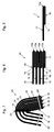
- the printed in a digital printing station web 1 has three juxtaposed, printed material web sections 2, 3 and 4 of the same width.
- FIG. 1a is the demarcation between the material web sections 2, 3 by dotted lines 5, 6, which extend in the longitudinal direction of the web 1, indicated.
- Each material web section 2, 3, 4 is printed with successive pages of a printed product, wherein in each case 3 sides a, b, c or d, e, f are arranged with their longitudinal sides running parallel to the longitudinal direction of the material web 1 side by side.
- the delimitation between the individual sides of each web strand 2, 3, 4 in the longitudinal direction of the web 1 is indicated by dotted lines 7, 8 and 9 respectively.
- the material web 1 coming from the digital printing station is moved forward in the direction of the arrow A which extends in the longitudinal direction of the material web 1.
- a first material web strand 10 formed by the material web section 4 is folded around a line 12 parallel to the feed direction A, which coincides with the delimitation line 6, against a second material web strand 11, which is formed by the two other material web sections 2 and 3, like that by the arrow B in FIG. 1a is indicated.
- the second material web strand 11 is twice as wide as the first material web strand 10.
- the material web 1 is perforated along the fold line 12, as shown in FIG FIG. 1a by the only schematically illustrated perforating tool 13 is indicated. This perforation, which serves as a preparation for later folding, can also be omitted.
- an adhesive is applied in the longitudinal direction of the material web 1 in the region of the center line of the material web strand 11, ie in the region of the delimitation line 5, to the second material web strand 11, as in FIG FIG. 1a indicated by the arrow C.
- FIG. 2 is shown in front view, the material web 1 with the two interconnected web strands 10, 11, wherein the adhesive connection with 14 and the folded edge is denoted by 12a.
- each partial product 15 is connected by means of an adhesive with the previously placed on the stack 20 partial product 15 in the region of the center line 19 of the second sheet 18, which coincides with the longitudinal center line of the wider web strand 11 and the later fold line.
- the application of an adhesive to the second sheet 18 is in Figure 1e indicated by the arrow D.
- FIG. 3 are shown in front view of the stack 20 superimposed partial products 15, wherein the adhesive connection between the partial products 15 is designated 21.
- the stacked partial products 15 are folded along a fold line 22 coinciding with the center line 19 of the second sheet 18 to form an end product 23, as shown in FIG. 1f is indicated by the arrow E.
- FIG. 4 is shown in front view of the folded end product 23, the folded edge is denoted by 24.
- the end product 23 is shown cut to the side edges 23a, 23b adjoining the fold edge 24 and to the side edge 23c lying opposite the fold edge 24.
- edge portions 25, 25 ', 25''cut away as symbolized by the scissors 26.
- the partial products 15 when stacked to stack 20 are not connected to each other, that is, the application of an adhesive between the superposed partial products 15 and thus the adhesive connection 21 accounts. This is from the FIG. 6 the remainder of the FIG. 3 equivalent.
- the superimposed partial products 15 are folded around a fold line 22 to a final product 23 ', wherein the stacked partial products 15 before or after folding along the fold line 22 and the folding edge 24 are connected together in an appropriate manner, preferably by stitching.
- the FIG. 7 , the the FIG. 4 shows, in front view, the folded and stapled end product 23 ', wherein the schematically illustrated stitching connection is denoted by 27.
- the final product 23 'can, as on hand of the Figure 1e be trimmed if necessary at the margins.
- This second embodiment differs from the first embodiment according to FIG. 1 by a different way of bringing together the two web strands 10 and 11. Therefore, for themselves corresponding features and parts in the FIG. 8 and the associated FIGS. 9 to 11 the same reference numerals as in the FIGS. 1 to 7 , In the description of this second embodiment is always on the description of the FIGS. 1 to 7 Referenced.
- the first, narrower material web strand 10 is not folded over against the second material web strand 11 as in the first embodiment, but along a cutting line 28 which runs parallel to the feed direction A and coincides with the delimitation line 6. separated from the second web strand 11, as in the FIG. 8a symbolized by the pair of scissors 29. Subsequently, the cut material web strand 10 is placed on the second web strand 11, that the two web strands 10 and 11 along one of its longitudinal edges 10 a, 11 a aligned with each other, as in FIG. 8a indicated by the arrow F.
- the application of the adhesive to the second material web strand in the longitudinal direction of the material web 1 in the region of the center line of the second material web strand 11, ie in the region of the delimitation line 5, is indicated by the arrow C.
- FIGS. 8b to 8g illustrated method steps, namely the separation of partial products 15 of the material web 1 with the second material web strand 11 and laid with this associated first web strand 10 (FIG. FIGS. 8b to 8d ), the stacking of the partial products 15 to a stack 20 (FIG. FIG. 8e ), the folding of the stacked partial products 15 along a fold line 22 to an end product 23 (FIG. FIG. 8f ) and the trimming of the final product 23 at the side edges 23a, 23b, 23c ( Figure 8g ) takes place in the same manner as in the first embodiment. It is therefore based on the corresponding explanations in the description of the method FIG. 1 directed.
- FIG. 9 shown in front view of material web 1 with superimposed and interconnected web strands 10, 11 differs from the in of the FIG. 2 shown material web 1 only in that the web strands 10, 11 are not connected to each other at their mutually aligned longitudinal edges 10a, 11a.
- FIGS. 9 to 11 will now be a variant of the second embodiment of the inventive method according to FIG. 8 explained.
- This variant corresponds to the variant according to the FIGS. 5 to 7 , That means that in the in the FIGS. 12 to 14 shown variant, the partial products 15 are not connected to each other when superimposed and thus the adhesive connection 21 is omitted. For this purpose, the stacked partial products 15 are joined together before or after folding along the folded edge 24, preferably by stitching.
- This booklet connection is in the FIG. 14 same as in the FIG. 7 denoted by 27.
- a processing line 30 having an unwinding station 31 for unwinding the web to be printed from a roll.
- This unwinding station 31 can be, for example, an unwinding module UW 6 distributed by the applicant.
- the unwind station 31 is a digital printing station 32 downstream.
- the material web printed in this digital printing station 32 is fed to a merging station 33, in which the web strands 10, 11 are brought together and connected to one another by means of an adhesive.
- the merging station 33 may be a longitudinal folding station of known type.
- the Georgia Pacific WGMA is a processing unit for separating the first web strand 10 from the second web strand 11 and then superimposing the two web strands 10, 11, as sold for example by the applicant under the name "Bahnmerger WM6-Even".
- a combined processing station as the merging station 33, which optionally brings together the material web strands 10, 11 according to the first embodiment or according to the second embodiment.
- Such a combined processing station is the subject of European patent application no. 08 009 232.2 dated May 20, 2008 and is sold by the assignee under the name "Folder-Merger FM6".
- Each embodiment of the merging station 33 is equipped with a device for connecting the two material web strands 10, 11 along a connecting line by means of an adhesive.
- the merging station 33 is followed by a cross cutting station 34 for separating the partial products 15.
- a cross cutting station 34 is suitable for the cross-cutting module CS6-I marketed by the applicant.
- the cross-cutting station 34 leaving partial products 15 are placed in a stacking station 35 to a stack 20 each other.
- a stacking station 35 is particularly suitable in the EP-A-1 471 022 described collection device, which is sold by the applicant under the name "Drum Collector DC7".
- the stacking station 35 is equipped with a device for applying an adhesive to the respective uppermost sub-product 15 in the stack 20 in the region of the later folding line.
- the stacked in the stacking station 35 partial products 15 are folded in a folding station 36 to a final product 23.
- a folding station 36 for example, in the EP-B-1 213 245 described folding device or a knife folding ZK500, the company Griesser & Kunzmann GmbH & CO. KG in Wellendingen (Federal Republic of Germany).
- the folding station 36 is adjoined by a side edge cutting station 37 in which the folded end products 23 are cut at the side edges 23a, 23b and 23c.
- This side edge cutting station 37 may be omitted under certain circumstances.
- the finished end products 23 are transferred to a removal module 38 at the end of the processing line 30.
- the production of end products takes place in a manner similar to that described above.
- the two together run material web strands have the same width and each consist of two juxtaposed, printed material web sections.
- the partial products produced in the manner described then consist of a folded, outer, printed sheet and arranged inside the outer sheet, folded, inside, printed sheet. The two sheets are connected to each other by means of an adhesive in the region of the folded edge of the outer sheet.
- the bonding of the superimposed partial products instead of by means of an applied before or during stacking of the partial products adhesive can be done by stitching the superimposed partial products along the fold line.
Abstract
Description
Die vorliegende Erfindung betrifft ein Verfahren und eine Vorrichtung zum Herstellen von mehrblättrigen, gefalzten Druckereierzeugnissen, insbesondere Zeitschriften und Broschüren, gemäss Oberbegriff des Anspruchs 1 bzw. des Anspruchs 9, sowie ein nach dem erfindungsgemässen Verfahren hergestelltes mehrblättriges, gefalztes Druckereierzeugnis.The present invention relates to a method and an apparatus for producing multi-leaved, folded printed products, especially magazines and brochures, according to the preamble of
Bei der Herstellung von Druckereierzeugnissen, wie Zeitschriften, Broschüren, Hefte und dgl., im Digitaldruck werden die Seiten eines Druckereierzeugnisses hintereinander gedruckt. Erst wenn alle Seiten eines Erzeugnisses gedruckt sind, wird mit dem Drucken des nächsten Erzeugnisses begonnen.In the production of printed matter such as magazines, brochures, booklets and the like. In digital printing, the pages of a printed product are printed one after the other. Only when all pages of a product have been printed does printing of the next product begin.
Mit den bisher zur Verfügung stehenden Digitaldruckern, mit denen Materialbahnen mit einer Bahnbreite von bis zu 50 cm bedruckt werden können, ist es möglich, bei der Herstellung von Druckerzeugnissen im Format DIN A4 (bzw. 81/2 x 11 zoll) zwei Seiten desselben Erzeugnisses, die mit ihrer Längsseite parallel zur Längserstreckung der Materialbahn verlaufen, nebeneinander zu drucken (sog. Doppelnutzen). Es werden aber bereits Digitaldruckmaschinen eingesetzt, die Materialbahnen mit einer Breite von 67 cm bedrucken können. Mit solchen Digitaldruckmaschinen können bei Druckereierzeugnissen im erwähnten Format DIN A4 drei Seiten desselben Erzeugnisses nebeneinander gedruckt werden (Dreifachnutzen).With the digital printers available so far, with which material webs with a web width of up to 50 cm can be printed, it is possible to produce two pages of the same product in the production of DIN A4 (or 81/2 x 11 inch) printed products , which run with their long side parallel to the longitudinal extent of the material web to print next to each other (so-called double-use). But there are already digital printing machines used that can print webs with a width of 67 cm. With such digital printing machines, three pages of the same product can be printed next to each other (triple benefit) for printed products in the above-mentioned DIN A4 format.
Der vorliegenden Erfindung liegt nun die Aufgabe zugrunde, ausgehend von einer in einer Digitaldruckmaschine bedruckten Materialbahn, die mit drei und mehr nebeneinander angeordneten Seiten eines Druckereierzeugnisses bedruckt ist, auf möglichst einfache und zeitsparende Weise und damit kostengünstig fertige Druckereierzeugnisse herzustellen.The present invention is based on the object, starting from a printed in a digital printing material web, which is printed with three and more juxtaposed pages of a printed product, in the simplest possible and time-saving manner and thus produce inexpensive finished printed products.
Diese Aufgabe wird erfindungsgemäss mit einem Verfahren mit den Merkmalen des Anspruchs 1 und mit einer Vorrichtung mit den Merkmalen des Anspruchs 9 gelöst. Das auf die erfindungsgemässe Weise hergestellte Druckereierzeugnis zeichnet sich durch die Merkmale des Anspruchs 15 bzw. des Anspruchs 16 aus.This object is achieved according to the invention by a method having the features of
Das Herstellen eines gefalzten Endprodukts ausgehend von einer Materialbahn mit drei und mehr nebeneinander angeordneten, bedruckten Materialbahnabschnitten läuft dabei auf einfache Weise wie folgt ab:The production of a folded end product starting from a material web with three and more printed material web sections arranged next to one another proceeds in a simple manner as follows:
In einem ersten Schritt wird bei sich vorwärts bewegender Materialbahn ein erster Materialbahnstrang mit einem zweiten Materialbahnstrang zusammengebracht und mit letzterem entlang einer Verbindungslinie, die in Längsrichtung der Materialbahn im Bereich einer späteren Falzlinie verläuft, mittels eines Klebstoffs verbunden. Das Zusammenführen der Materialbahnstränge kann dabei auf verschiedene Weise erfolgen, vorzugsweise jedoch wie in den Ansprüchen 5 und 6 definiert.In a first step, when the material web advances, a first material web strand is brought together with a second material web strand and joined to the latter along a connecting line extending in the longitudinal direction of the material web in the region of a later fold line by means of an adhesive. The merging of the web strands can be carried out in various ways, but preferably as defined in
In einem zweiten Schritt werden von den beiden miteinander verbundenen und sich vorwärts bewegenden Materialbahnsträngen durch Querschneiden kontinuierlich Teilprodukte abgetrennt. Diese Teilprodukte werden in einem dritten Schritt zu einem Stapel gestapelt. Beim Stapeln oder nach dem Stapeln werden die Teilprodukte in einem vierten Schritt miteinander verbunden.In a second step, partial products are continuously separated from the two interconnected and moving material web strands by transverse cutting. These partial products are stacked in a third step to a stack. At the Stacking or after stacking, the partial products are joined together in a fourth step.
In einem weitern, fünften Schritt werden die Teilprodukte einzeln, d.h. vor dem Stapeln, oder als Stapel gefalzt.In a fifth step, the partial products are treated individually, i. before stacking, or folded as a stack.
Auf entsprechende Weise lassen sich gemäss Anspruch 8 auch Endprodukte aus einer bedruckten Materialbahn, die vier nebeneinander angeordnete, bedruckte Materialbahnabschnitte aufweist, herstellen.In a corresponding manner, end products can also be produced from a printed material web which has four printed material web sections arranged next to one another.
Andere bevorzugte Weiterausgestaltungen des erfindungsgemässen Verfahrens und der erfindungsgemässen Vorrichtung bilden Gegenstand der übrigen abhängigen Ansprüche.Other preferred further developments of the inventive method and the inventive device form the subject of the other dependent claims.
Im Folgenden wird die Erfindung anhand der Zeichnungen nähe erläutert. Es zeigen rein schematisch:
- Fig. 1
- den Ablauf des erfindungsgemässen Verfahrens bei einer ersten Ausführungsform,
- Fig. 2
- in einer Vorderansicht die beiden im Verlauf des Verfahrens gemäss
Fig. 1 zusammengeführten und miteinander verbundenen Materialbahnstränge, - Fig. 3
- in Vorderansicht die im Verlauf des Verfahrens gemäss
Fig. 1 zu einem Stapel aufeinander gelegten und miteinander verbundenen Teilprodukte, - Fig. 4
- in Vorderansicht ein nach dem Verfahren gemäss
Fig.1 hergestelltes gefalztes Endprodukt, - Fig. 5-7
- in, den
Fig. 2 bis 4 entsprechenden, Darstellungen Zwischen- und Endprodukte, die gemäss einer Variante des in derFig. 1 dargestellten Verfahrens hergestellt sind, - Fig. 8
- den Ablauf des erfindungsgemässen Verfahrens bei einer zweiten Ausführungsform,
- Fig. 9
- in einer Vorderansicht die beiden im Verlauf des Verfahrens gemäss
Fig. 8 zusammengeführten und miteinander verbundenen Materialbahnstränge, - Fig. 10
- in Vorderansicht die im Verlauf des Verfahrens gemäss
Fig. 8 zu einem Stapel aufeinander gelegten Teilprodukte, - Fig. 11
- in Vorderansicht ein nach dem Verfahren gemäss
Fig. 8 hergestelltes gefalztes Endprodukt, - Fig. 12-14
- in, den
Fig. 9 bis 11 entsprechenden, Darstellungen Zwischen- und Endprodukte, die gemäss einer Variante des in derFig. 8 dargestellten Verfahrens hergestellt sind, und - Fig. 15
- in Draufsicht eine Anlage zur Herstellung von Druckereierzeugnissen nach dem Verfahren gemäss
Fig. 1 .
- Fig. 1
- the sequence of the inventive method in a first embodiment,
- Fig. 2
- in a front view, the two in the course of the process according to
Fig. 1 merged and interconnected web strands, - Fig. 3
- in front view in the course of the procedure according to
Fig. 1 to a stack of stacked and interconnected subproducts, - Fig. 4
- in front view according to the method according to
Fig.1 produced folded end product, - Fig. 5-7
- in the
Fig. 2 to 4 corresponding representations intermediate and end products, which according to a variant of the in theFig. 1 prepared method are produced, - Fig. 8
- the sequence of the inventive method in a second embodiment,
- Fig. 9
- in a front view, the two in the course of the process according to
Fig. 8 merged and interconnected web strands, - Fig. 10
- in front view in the course of the procedure according to
Fig. 8 to a stack of stacked sub-products, - Fig. 11
- in front view according to the method according to
Fig. 8 produced folded end product, - Fig. 12-14
- in the
Fig. 9 to 11 corresponding representations intermediate and end products, which according to a variant of the in theFig. 8 are shown, and - Fig. 15
- in plan view a plant for the production of printed products according to the method according to
Fig. 1 ,
An Hand der Figuren wird nun eine erste Ausführungsform des erfindungsgemässen Verfahrens erläutert.A first embodiment of the method according to the invention will now be explained with reference to the figures.
Die in einer Digitaldruckstation bedruckte Materialbahn 1 weist drei nebeneinander angeordnete, bedruckte Materialbahnabschnitte 2, 3 und 4 gleicher Breite auf. In der
Die von der Digitaldruckstation kommende Materialbahn 1 wird in Richtung des Pfeils A, die in Längsrichtung der Materialbahn 1 verläuft, vorwärts bewegt. Während dieser Vorwärtsbewegung wird ein durch den Materialbahnabschnitt 4 gebildeter erster Materialbahnstrang 10 um eine parallel zur Vorschubrichtung A verlaufende Linie 12, die mit der Abgrenzungslinie 6 zusammenfällt, gegen einen zweiten Materialbahnstrang 11, der durch die beiden anderen Materialbahnabschnitte 2 und 3 gebildet wird, gefalzt, wie das durch den Pfeil B in
Zum Verbinden der auf diese Weise zusammen geführten Materialbahnstränge 10 und 11 wird in Längsrichtung der Materialbahn 1 im Bereich der Mittellinie des Materialbahnstranges 11, d.h. im Bereich der Abgrenzungslinie 5, auf den zweiten Materialbahnstrang 11 ein Klebstoff aufgetragen, wie das in
Von der in Vorschubrichtung A weiter vorgeschobenen Materialbahn 1 mit dem gegen den zweiten Materialbahnstrang 11 umgelegten und mit letzterem verklebten ersten Materialbahnstrang 10 (
Diese Teilprodukte 15 (
Im nachfolgenden Verfahrensschritt werden die gestapelten Teilprodukte 15 entlang einer mit der Mittellinie 19 der zweiten Bogen 18 zusammenfallenden Falzlinie 22 zu einem Endprodukt 23 gefalzt, wie das in
Wie in der
Das Wegschneiden der Randabschnitte 25 und 25' kann unter Umständen entfallen, z.B, dann, wenn an die Qualität des Endprodukts 23 keine allzu hohen Anforderungen gestellt werden.The cutting away of the
Unter Bezugnahme auf die
Bei dieser Variante erfolgt das Umfalzen des ersten Materialbandstrangs 10 und das Verkleben des letzteren mit dem zweiten Materialbahnstrang 11 gleich wie beim an Hand der
Anders als beim an Hand der
Die aufeinander liegenden Teilprodukte 15 werden um eine Falzlinie 22 zu einem Endprodukt 23' gefalzt, wobei die gestapelten Teilprodukte 15 vor oder nach dem Falzen entlang der Falzlinie 22 bzw. der Faltkante 24 auf eine geeignete Weise miteinander verbunden werden, vorzugsweise durch Heften. Die
Das Endprodukt 23' kann, wie an Hand der
Nachfolgend wir an Hand der
Diese zweite Ausführungsform unterscheidet sich von der ersten Ausführungsform gemäss
Bei der Vorwärtsbewegung der aus einer Digitaldruckstation kommenden, bedruckten Materialbahn 1 wird der erste, schmalere Materialbahnstrang 10 nicht wie bei der ersten Ausführungsform gegen den zweiten Materialbahnstrang 11 umgefalzt, sondern entlang einer parallel zur Vorschubrichtung A verlaufenden Schnittlinie 28, die mit der Abgrenzungslinie 6 zusammenfällt, vom zweiten Materialbahnstrang 11 abgetrennt, wie das in der
Die weiteren, in den
Die in der
An Hand der
Diese Variante entspricht der Variante gemäss den
An Hand der
In der
Der Zusammenführstation 33 ist eine Querschneidstation 34 zum Abtrennen der Teilprodukte 15 nachgeschaltet. Als eine solche Querschneidstation 34 eignet sich das von der Anmelderin vertriebene Querschneidmodul CS6-I.The merging
Die die Querschneidstation 34 verlassenden Teilprodukte 15 werden in einer Stapelstation 35 zu einem Stapel 20 aufeinander gelegt. Als Stapelstation 35 eignet sich ganz besonders die in der
Die in der Stapelstation 35 gestapelten Teilprodukte 15 werden in einer Falzstation 36 zu einem Endprodukt 23 gefalzt. Für die Falzstation 36 kann beispielsweise die in der
An die Falzstation 36 schliesst eine Seitenrandschneidstation 37 an, in der die gefalzten Endprodukte 23 an den Seitenrändern 23a, 23b und 23c beschnitten wird. Diese Seitenrandschneidstation 37 kann unter Umständen entfallen.The
Die fertigen Endprodukte 23 werden am Ende der Verarbeitungslinie 30 einem Wegführmodul 38 übergeben.The
Für die Durchführung der Variante der ersten und zweiten' Ausführungsform des erfindungsgemässen verfahrens wird die in
Wird die Materialbahn 1 in der Digitaldruckstation 32 so bedruckt, dass 4 bedruckte Materialbahnabschnitte nebeneinander angeordnet sind, so erfolgt das Herstellen von Endprodukten ähnlich wie vorstehend beschrieben. Im Gegensatz zu den an Hand der
Nachfolgend wird ein drittes, in den Figuren nicht gezeigtes Ausführungsbeispiel des Erfindungsgegenstands beschrieben, bei dem das Stapeln der Teilprodukte 15 und das verbinden derselben miteinander anders als bei den Ausführungsbeispielen gemäss den
Bei einer Variante dieses dritten Ausführungsbeispiels kann das Verbinden der übereinander liegenden Teilprodukte statt mittels eines vor oder beim Stapeln der Teilprodukte aufgetragenen Klebstoffs durch Heften der übereinander liegenden Teilprodukte entlang deren Falzlinie erfolgen.In a variant of this third embodiment, the bonding of the superimposed partial products instead of by means of an applied before or during stacking of the partial products adhesive can be done by stitching the superimposed partial products along the fold line.
Claims (16)
Priority Applications (3)
| Application Number | Priority Date | Filing Date | Title |
|---|---|---|---|
| EP08012915.8A EP2145773B1 (en) | 2008-07-17 | 2008-07-17 | Device and method for producing multi-sheet, folded printed products, in particular magazines and brochures |
| US12/458,639 US8871047B2 (en) | 2008-07-17 | 2009-07-17 | Method of, and apparatus for, producing multi-leaf, folded printed products, in particular periodicals and brochures |
| US14/296,902 US9555659B2 (en) | 2008-07-17 | 2014-06-05 | Method of, and apparatus for, producing multi-leaf, folded printed products, in particular periodicals and brochures |
Applications Claiming Priority (1)
| Application Number | Priority Date | Filing Date | Title |
|---|---|---|---|
| EP08012915.8A EP2145773B1 (en) | 2008-07-17 | 2008-07-17 | Device and method for producing multi-sheet, folded printed products, in particular magazines and brochures |
Publications (2)
| Publication Number | Publication Date |
|---|---|
| EP2145773A1 true EP2145773A1 (en) | 2010-01-20 |
| EP2145773B1 EP2145773B1 (en) | 2016-09-14 |
Family
ID=40350253
Family Applications (1)
| Application Number | Title | Priority Date | Filing Date |
|---|---|---|---|
| EP08012915.8A Active EP2145773B1 (en) | 2008-07-17 | 2008-07-17 | Device and method for producing multi-sheet, folded printed products, in particular magazines and brochures |
Country Status (2)
| Country | Link |
|---|---|
| US (2) | US8871047B2 (en) |
| EP (1) | EP2145773B1 (en) |
Cited By (5)
| Publication number | Priority date | Publication date | Assignee | Title |
|---|---|---|---|---|
| EP2484617A1 (en) * | 2011-02-07 | 2012-08-08 | Heidelberger Druckmaschinen AG | Folding machine with a device for cutting fold edges and method for folding sheets |
| WO2013067650A1 (en) | 2011-11-10 | 2013-05-16 | Hunkeler Ag | Method for producing printed products consisting of at least three sub-products |
| DE102014205939A1 (en) * | 2014-03-31 | 2015-10-01 | Koenig & Bauer Ag | Method and device for producing a printed product and printed product |
| DE102016015200A1 (en) * | 2016-12-21 | 2018-06-21 | Bernd Rose | Document with paper pages of different thicknesses |
| DE102022124182A1 (en) | 2022-09-21 | 2024-03-21 | Müller Martini Holding AG | Dynamic benefit change |
Families Citing this family (3)
| Publication number | Priority date | Publication date | Assignee | Title |
|---|---|---|---|---|
| WO2016207977A1 (en) * | 2015-06-23 | 2016-12-29 | ホリゾン・インターナショナル株式会社 | Book block forming apparatus |
| US10751968B2 (en) * | 2015-06-30 | 2020-08-25 | Vsl International Ag | Cylindrical thermal protection sheath |
| US11071419B2 (en) * | 2017-04-28 | 2021-07-27 | Novex Products Incorporated | Tabbed easy sliding interfolded dispenser napkins |
Citations (12)
| Publication number | Priority date | Publication date | Assignee | Title |
|---|---|---|---|---|
| DE3016573A1 (en) * | 1980-04-30 | 1981-11-05 | Fried. Krupp Gmbh, 4300 Essen | Advertising folder made from printed web - is made into six sheets and covers by adhesive coating, perforating and folding sequence |
| US5156384A (en) * | 1991-11-04 | 1992-10-20 | Webcraft Technologies, Inc. | Collect tab stacking method with transverse cutting stage forming inserts and indexing inserts |
| US5242521A (en) * | 1991-09-25 | 1993-09-07 | The Lehigh Press, Inc. | Method of making a controllable fragrance sampler |
| FR2721009A1 (en) * | 1994-06-10 | 1995-12-15 | Packart | Installation for producing and packaging printed documents |
| US20010040371A1 (en) * | 2000-02-17 | 2001-11-15 | Dahlquist | Coupon booklet and method |
| EP1288015A1 (en) * | 2001-09-03 | 2003-03-05 | Grapha-Holding AG | Method for the, at least partially synchronized, production of bound printed products such as books, magazines or similar |
| EP1213245B1 (en) | 2000-11-28 | 2003-10-08 | Hunkeler AG | Method and device for folding sheets |
| EP1431025A2 (en) * | 2002-12-20 | 2004-06-23 | Eukerdruck GmbH & Co. KG | Process for making folded and glued rolled inserts |
| EP1471022A1 (en) | 2003-04-22 | 2004-10-27 | Hunkeler AG | Collecting device and method for operating the same |
| US20040222583A1 (en) * | 2003-05-08 | 2004-11-11 | Maschinenbau Oppenweiler Binder Gmbh & Co. Kg | Method of, and apparatus for, processing sheets further to produce multi-leaf printed products |
| WO2005072980A2 (en) | 2004-01-28 | 2005-08-11 | Ibis Integrated Bindery Systems Limited | Process for binding sheets |
| EP1661673A1 (en) * | 2004-11-23 | 2006-05-31 | Rotanotice | Method and device for aligning the edges of webs |
Family Cites Families (4)
| Publication number | Priority date | Publication date | Assignee | Title |
|---|---|---|---|---|
| US3697061A (en) * | 1971-03-24 | 1972-10-10 | Sidney V Levine | Method and apparatus for making twelve-page booklets or signatures |
| US3917251A (en) * | 1974-01-25 | 1975-11-04 | S & F Delise Realty Corp | Method for the high speed folding of sheet paper |
| US6010122A (en) * | 1997-05-16 | 2000-01-04 | Wallace Computer Services, Inc. | Method and apparatus for producing high page count signatures |
| EP1005984B1 (en) * | 1998-11-27 | 2004-07-07 | Hunkeler AG Papierverarbeitungsmaschinen | Method for realising a printed, bound product and the printed product |
-
2008
- 2008-07-17 EP EP08012915.8A patent/EP2145773B1/en active Active
-
2009
- 2009-07-17 US US12/458,639 patent/US8871047B2/en active Active
-
2014
- 2014-06-05 US US14/296,902 patent/US9555659B2/en active Active
Patent Citations (12)
| Publication number | Priority date | Publication date | Assignee | Title |
|---|---|---|---|---|
| DE3016573A1 (en) * | 1980-04-30 | 1981-11-05 | Fried. Krupp Gmbh, 4300 Essen | Advertising folder made from printed web - is made into six sheets and covers by adhesive coating, perforating and folding sequence |
| US5242521A (en) * | 1991-09-25 | 1993-09-07 | The Lehigh Press, Inc. | Method of making a controllable fragrance sampler |
| US5156384A (en) * | 1991-11-04 | 1992-10-20 | Webcraft Technologies, Inc. | Collect tab stacking method with transverse cutting stage forming inserts and indexing inserts |
| FR2721009A1 (en) * | 1994-06-10 | 1995-12-15 | Packart | Installation for producing and packaging printed documents |
| US20010040371A1 (en) * | 2000-02-17 | 2001-11-15 | Dahlquist | Coupon booklet and method |
| EP1213245B1 (en) | 2000-11-28 | 2003-10-08 | Hunkeler AG | Method and device for folding sheets |
| EP1288015A1 (en) * | 2001-09-03 | 2003-03-05 | Grapha-Holding AG | Method for the, at least partially synchronized, production of bound printed products such as books, magazines or similar |
| EP1431025A2 (en) * | 2002-12-20 | 2004-06-23 | Eukerdruck GmbH & Co. KG | Process for making folded and glued rolled inserts |
| EP1471022A1 (en) | 2003-04-22 | 2004-10-27 | Hunkeler AG | Collecting device and method for operating the same |
| US20040222583A1 (en) * | 2003-05-08 | 2004-11-11 | Maschinenbau Oppenweiler Binder Gmbh & Co. Kg | Method of, and apparatus for, processing sheets further to produce multi-leaf printed products |
| WO2005072980A2 (en) | 2004-01-28 | 2005-08-11 | Ibis Integrated Bindery Systems Limited | Process for binding sheets |
| EP1661673A1 (en) * | 2004-11-23 | 2006-05-31 | Rotanotice | Method and device for aligning the edges of webs |
Cited By (9)
| Publication number | Priority date | Publication date | Assignee | Title |
|---|---|---|---|---|
| EP2484617A1 (en) * | 2011-02-07 | 2012-08-08 | Heidelberger Druckmaschinen AG | Folding machine with a device for cutting fold edges and method for folding sheets |
| WO2013067650A1 (en) | 2011-11-10 | 2013-05-16 | Hunkeler Ag | Method for producing printed products consisting of at least three sub-products |
| JP2014534099A (en) * | 2011-11-10 | 2014-12-18 | フンケラー アクチェンゲゼルシャフト | Method for producing a printed product comprising at least three partial products |
| DE102014205939A1 (en) * | 2014-03-31 | 2015-10-01 | Koenig & Bauer Ag | Method and device for producing a printed product and printed product |
| DE102014205939B4 (en) * | 2014-03-31 | 2020-09-17 | Koenig & Bauer Ag | Method and device for the production of a printed product |
| DE102016015200A1 (en) * | 2016-12-21 | 2018-06-21 | Bernd Rose | Document with paper pages of different thicknesses |
| US10857781B2 (en) | 2016-12-21 | 2020-12-08 | Bernd Rose | Method and device for producing documents |
| DE102022124182A1 (en) | 2022-09-21 | 2024-03-21 | Müller Martini Holding AG | Dynamic benefit change |
| EP4349610A2 (en) | 2022-09-21 | 2024-04-10 | Müller Martini Holding AG | Dynamic utility switching |
Also Published As
| Publication number | Publication date |
|---|---|
| US20100015414A1 (en) | 2010-01-21 |
| US8871047B2 (en) | 2014-10-28 |
| US9555659B2 (en) | 2017-01-31 |
| US20140353958A1 (en) | 2014-12-04 |
| EP2145773B1 (en) | 2016-09-14 |
Similar Documents
| Publication | Publication Date | Title |
|---|---|---|
| EP2159070B1 (en) | Device and method for manufacturing piles of book blocks | |
| EP2145773B1 (en) | Device and method for producing multi-sheet, folded printed products, in particular magazines and brochures | |
| EP1733988B1 (en) | Process and apparatus for the production of newspapers | |
| DE2558049A1 (en) | PROCESS FOR MANUFACTURING A PRINTED PRODUCT AND ROTARY PRINTING MACHINE FOR CARRYING OUT THE PROCESS | |
| EP1802466A2 (en) | Method and printing machine for producing a printed product with a number of volumes | |
| EP2776252B1 (en) | Method for producing printed products consisting of at least three sub-products | |
| DE3016573A1 (en) | Advertising folder made from printed web - is made into six sheets and covers by adhesive coating, perforating and folding sequence | |
| EP3251869B1 (en) | Method for producing printed products with integrated envelope | |
| DE102010027410B4 (en) | Process for producing an overprinted printed product | |
| DE102014205939B4 (en) | Method and device for the production of a printed product | |
| EP1834804B1 (en) | Method and device for applying a cover | |
| EP2165847B1 (en) | Device and method for manufacturing printed products | |
| DE102015202379B4 (en) | Process for the production of a printed product | |
| DE102014205938B4 (en) | Method for producing a printed product in a printing machine | |
| EP2813369B1 (en) | Method for producing a printed product, in particular a package insert, and printed product | |
| DE10259655B3 (en) | Stream mixing device for combining of printed sheets in printing process has stapler located on one guide path for stapling of part stream guided on this guide path | |
| DE3305760C2 (en) | ||
| DE3312931A1 (en) | Method of producing brochures having at least sixteen pages from one sheet | |
| DE591271C (en) | Method for folding into one another endless, printed paper webs coming from different printing units | |
| DE102016215373A1 (en) | Process for the preparation of a printed product and printed product | |
| DE102016216429B4 (en) | Printed product, method and web-fed printing machine for producing a printed product | |
| DE102013201901B4 (en) | Method and device for producing a multilayer printed product and printing machine | |
| DE102015202381B3 (en) | Method and device for producing a printed product | |
| DE102014222387B4 (en) | Process for the production of a printed product as well as a printed product | |
| DE102015202378B4 (en) | Printed product |
Legal Events
| Date | Code | Title | Description |
|---|---|---|---|
| PUAI | Public reference made under article 153(3) epc to a published international application that has entered the european phase |
Free format text: ORIGINAL CODE: 0009012 |
|
| AK | Designated contracting states |
Kind code of ref document: A1 Designated state(s): AT BE BG CH CY CZ DE DK EE ES FI FR GB GR HR HU IE IS IT LI LT LU LV MC MT NL NO PL PT RO SE SI SK TR |
|
| AX | Request for extension of the european patent |
Extension state: AL BA MK RS |
|
| 17P | Request for examination filed |
Effective date: 20100709 |
|
| AKX | Designation fees paid |
Designated state(s): AT BE BG CH CY CZ DE DK EE ES FI FR GB GR HR HU IE IS IT LI LT LU LV MC MT NL NO PL PT RO SE SI SK TR |
|
| 17Q | First examination report despatched |
Effective date: 20110916 |
|
| GRAP | Despatch of communication of intention to grant a patent |
Free format text: ORIGINAL CODE: EPIDOSNIGR1 |
|
| INTG | Intention to grant announced |
Effective date: 20151104 |
|
| GRAS | Grant fee paid |
Free format text: ORIGINAL CODE: EPIDOSNIGR3 |
|
| GRAP | Despatch of communication of intention to grant a patent |
Free format text: ORIGINAL CODE: EPIDOSNIGR1 |
|
| INTG | Intention to grant announced |
Effective date: 20160520 |
|
| GRAS | Grant fee paid |
Free format text: ORIGINAL CODE: EPIDOSNIGR3 |
|
| GRAA | (expected) grant |
Free format text: ORIGINAL CODE: 0009210 |
|
| AK | Designated contracting states |
Kind code of ref document: B1 Designated state(s): AT BE BG CH CY CZ DE DK EE ES FI FR GB GR HR HU IE IS IT LI LT LU LV MC MT NL NO PL PT RO SE SI SK TR |
|
| REG | Reference to a national code |
Ref country code: GB Ref legal event code: FG4D Free format text: NOT ENGLISH |
|
| REG | Reference to a national code |
Ref country code: CH Ref legal event code: EP |
|
| REG | Reference to a national code |
Ref country code: CH Ref legal event code: NV Representative=s name: PATENTANWAELTE SCHAAD, BALASS, MENZL AND PARTN, CH |
|
| REG | Reference to a national code |
Ref country code: IE Ref legal event code: FG4D Free format text: LANGUAGE OF EP DOCUMENT: GERMAN |
|
| REG | Reference to a national code |
Ref country code: AT Ref legal event code: REF Ref document number: 828512 Country of ref document: AT Kind code of ref document: T Effective date: 20161015 |
|
| REG | Reference to a national code |
Ref country code: DE Ref legal event code: R096 Ref document number: 502008014625 Country of ref document: DE |
|
| REG | Reference to a national code |
Ref country code: SE Ref legal event code: TRGR |
|
| REG | Reference to a national code |
Ref country code: LT Ref legal event code: MG4D |
|
| REG | Reference to a national code |
Ref country code: NL Ref legal event code: MP Effective date: 20160914 |
|
| PG25 | Lapsed in a contracting state [announced via postgrant information from national office to epo] |
Ref country code: NO Free format text: LAPSE BECAUSE OF FAILURE TO SUBMIT A TRANSLATION OF THE DESCRIPTION OR TO PAY THE FEE WITHIN THE PRESCRIBED TIME-LIMIT Effective date: 20161214 Ref country code: HR Free format text: LAPSE BECAUSE OF FAILURE TO SUBMIT A TRANSLATION OF THE DESCRIPTION OR TO PAY THE FEE WITHIN THE PRESCRIBED TIME-LIMIT Effective date: 20160914 Ref country code: LT Free format text: LAPSE BECAUSE OF FAILURE TO SUBMIT A TRANSLATION OF THE DESCRIPTION OR TO PAY THE FEE WITHIN THE PRESCRIBED TIME-LIMIT Effective date: 20160914 Ref country code: FI Free format text: LAPSE BECAUSE OF FAILURE TO SUBMIT A TRANSLATION OF THE DESCRIPTION OR TO PAY THE FEE WITHIN THE PRESCRIBED TIME-LIMIT Effective date: 20160914 |
|
| PG25 | Lapsed in a contracting state [announced via postgrant information from national office to epo] |
Ref country code: ES Free format text: LAPSE BECAUSE OF FAILURE TO SUBMIT A TRANSLATION OF THE DESCRIPTION OR TO PAY THE FEE WITHIN THE PRESCRIBED TIME-LIMIT Effective date: 20160914 Ref country code: NL Free format text: LAPSE BECAUSE OF FAILURE TO SUBMIT A TRANSLATION OF THE DESCRIPTION OR TO PAY THE FEE WITHIN THE PRESCRIBED TIME-LIMIT Effective date: 20160914 Ref country code: LV Free format text: LAPSE BECAUSE OF FAILURE TO SUBMIT A TRANSLATION OF THE DESCRIPTION OR TO PAY THE FEE WITHIN THE PRESCRIBED TIME-LIMIT Effective date: 20160914 Ref country code: GR Free format text: LAPSE BECAUSE OF FAILURE TO SUBMIT A TRANSLATION OF THE DESCRIPTION OR TO PAY THE FEE WITHIN THE PRESCRIBED TIME-LIMIT Effective date: 20161215 |
|
| PG25 | Lapsed in a contracting state [announced via postgrant information from national office to epo] |
Ref country code: EE Free format text: LAPSE BECAUSE OF FAILURE TO SUBMIT A TRANSLATION OF THE DESCRIPTION OR TO PAY THE FEE WITHIN THE PRESCRIBED TIME-LIMIT Effective date: 20160914 Ref country code: RO Free format text: LAPSE BECAUSE OF FAILURE TO SUBMIT A TRANSLATION OF THE DESCRIPTION OR TO PAY THE FEE WITHIN THE PRESCRIBED TIME-LIMIT Effective date: 20160914 |
|
| PG25 | Lapsed in a contracting state [announced via postgrant information from national office to epo] |
Ref country code: CZ Free format text: LAPSE BECAUSE OF FAILURE TO SUBMIT A TRANSLATION OF THE DESCRIPTION OR TO PAY THE FEE WITHIN THE PRESCRIBED TIME-LIMIT Effective date: 20160914 Ref country code: PT Free format text: LAPSE BECAUSE OF FAILURE TO SUBMIT A TRANSLATION OF THE DESCRIPTION OR TO PAY THE FEE WITHIN THE PRESCRIBED TIME-LIMIT Effective date: 20170116 Ref country code: SK Free format text: LAPSE BECAUSE OF FAILURE TO SUBMIT A TRANSLATION OF THE DESCRIPTION OR TO PAY THE FEE WITHIN THE PRESCRIBED TIME-LIMIT Effective date: 20160914 Ref country code: BG Free format text: LAPSE BECAUSE OF FAILURE TO SUBMIT A TRANSLATION OF THE DESCRIPTION OR TO PAY THE FEE WITHIN THE PRESCRIBED TIME-LIMIT Effective date: 20161214 Ref country code: IS Free format text: LAPSE BECAUSE OF FAILURE TO SUBMIT A TRANSLATION OF THE DESCRIPTION OR TO PAY THE FEE WITHIN THE PRESCRIBED TIME-LIMIT Effective date: 20170114 Ref country code: PL Free format text: LAPSE BECAUSE OF FAILURE TO SUBMIT A TRANSLATION OF THE DESCRIPTION OR TO PAY THE FEE WITHIN THE PRESCRIBED TIME-LIMIT Effective date: 20160914 |
|
| REG | Reference to a national code |
Ref country code: DE Ref legal event code: R097 Ref document number: 502008014625 Country of ref document: DE |
|
| PLBE | No opposition filed within time limit |
Free format text: ORIGINAL CODE: 0009261 |
|
| STAA | Information on the status of an ep patent application or granted ep patent |
Free format text: STATUS: NO OPPOSITION FILED WITHIN TIME LIMIT |
|
| REG | Reference to a national code |
Ref country code: FR Ref legal event code: PLFP Year of fee payment: 10 |
|
| PG25 | Lapsed in a contracting state [announced via postgrant information from national office to epo] |
Ref country code: DK Free format text: LAPSE BECAUSE OF FAILURE TO SUBMIT A TRANSLATION OF THE DESCRIPTION OR TO PAY THE FEE WITHIN THE PRESCRIBED TIME-LIMIT Effective date: 20160914 |
|
| 26N | No opposition filed |
Effective date: 20170615 |
|
| PG25 | Lapsed in a contracting state [announced via postgrant information from national office to epo] |
Ref country code: SI Free format text: LAPSE BECAUSE OF FAILURE TO SUBMIT A TRANSLATION OF THE DESCRIPTION OR TO PAY THE FEE WITHIN THE PRESCRIBED TIME-LIMIT Effective date: 20160914 |
|
| REG | Reference to a national code |
Ref country code: IE Ref legal event code: MM4A |
|
| PG25 | Lapsed in a contracting state [announced via postgrant information from national office to epo] |
Ref country code: IE Free format text: LAPSE BECAUSE OF NON-PAYMENT OF DUE FEES Effective date: 20170717 |
|
| REG | Reference to a national code |
Ref country code: BE Ref legal event code: MM Effective date: 20170731 |
|
| PG25 | Lapsed in a contracting state [announced via postgrant information from national office to epo] |
Ref country code: LU Free format text: LAPSE BECAUSE OF NON-PAYMENT OF DUE FEES Effective date: 20170717 |
|
| REG | Reference to a national code |
Ref country code: FR Ref legal event code: PLFP Year of fee payment: 11 |
|
| PG25 | Lapsed in a contracting state [announced via postgrant information from national office to epo] |
Ref country code: BE Free format text: LAPSE BECAUSE OF NON-PAYMENT OF DUE FEES Effective date: 20170731 |
|
| REG | Reference to a national code |
Ref country code: AT Ref legal event code: MM01 Ref document number: 828512 Country of ref document: AT Kind code of ref document: T Effective date: 20170717 |
|
| PG25 | Lapsed in a contracting state [announced via postgrant information from national office to epo] |
Ref country code: MT Free format text: LAPSE BECAUSE OF FAILURE TO SUBMIT A TRANSLATION OF THE DESCRIPTION OR TO PAY THE FEE WITHIN THE PRESCRIBED TIME-LIMIT Effective date: 20160914 |
|
| PG25 | Lapsed in a contracting state [announced via postgrant information from national office to epo] |
Ref country code: AT Free format text: LAPSE BECAUSE OF NON-PAYMENT OF DUE FEES Effective date: 20170717 |
|
| PG25 | Lapsed in a contracting state [announced via postgrant information from national office to epo] |
Ref country code: HU Free format text: LAPSE BECAUSE OF FAILURE TO SUBMIT A TRANSLATION OF THE DESCRIPTION OR TO PAY THE FEE WITHIN THE PRESCRIBED TIME-LIMIT; INVALID AB INITIO Effective date: 20080717 Ref country code: MC Free format text: LAPSE BECAUSE OF FAILURE TO SUBMIT A TRANSLATION OF THE DESCRIPTION OR TO PAY THE FEE WITHIN THE PRESCRIBED TIME-LIMIT Effective date: 20160914 |
|
| PG25 | Lapsed in a contracting state [announced via postgrant information from national office to epo] |
Ref country code: CY Free format text: LAPSE BECAUSE OF NON-PAYMENT OF DUE FEES Effective date: 20160914 |
|
| PG25 | Lapsed in a contracting state [announced via postgrant information from national office to epo] |
Ref country code: TR Free format text: LAPSE BECAUSE OF FAILURE TO SUBMIT A TRANSLATION OF THE DESCRIPTION OR TO PAY THE FEE WITHIN THE PRESCRIBED TIME-LIMIT Effective date: 20160914 |
|
| P01 | Opt-out of the competence of the unified patent court (upc) registered |
Effective date: 20230510 |
|
| PGFP | Annual fee paid to national office [announced via postgrant information from national office to epo] |
Ref country code: IT Payment date: 20230724 Year of fee payment: 16 Ref country code: GB Payment date: 20230720 Year of fee payment: 16 Ref country code: CH Payment date: 20230801 Year of fee payment: 16 |
|
| PGFP | Annual fee paid to national office [announced via postgrant information from national office to epo] |
Ref country code: SE Payment date: 20230719 Year of fee payment: 16 Ref country code: FR Payment date: 20230725 Year of fee payment: 16 Ref country code: DE Payment date: 20230719 Year of fee payment: 16 |