EP2143098B1 - Revêtement léger d'isolation acoustique pour pièce de carrosserie d'un véhicule à moteur et son procédé de réalisation - Google Patents
Revêtement léger d'isolation acoustique pour pièce de carrosserie d'un véhicule à moteur et son procédé de réalisation Download PDFInfo
- Publication number
- EP2143098B1 EP2143098B1 EP08736279.4A EP08736279A EP2143098B1 EP 2143098 B1 EP2143098 B1 EP 2143098B1 EP 08736279 A EP08736279 A EP 08736279A EP 2143098 B1 EP2143098 B1 EP 2143098B1
- Authority
- EP
- European Patent Office
- Prior art keywords
- layer
- porous
- sound absorbing
- absorbing layer
- lining
- Prior art date
- Legal status (The legal status is an assumption and is not a legal conclusion. Google has not performed a legal analysis and makes no representation as to the accuracy of the status listed.)
- Not-in-force
Links
Images


Classifications
-
- G—PHYSICS
- G10—MUSICAL INSTRUMENTS; ACOUSTICS
- G10K—SOUND-PRODUCING DEVICES; METHODS OR DEVICES FOR PROTECTING AGAINST, OR FOR DAMPING, NOISE OR OTHER ACOUSTIC WAVES IN GENERAL; ACOUSTICS NOT OTHERWISE PROVIDED FOR
- G10K11/00—Methods or devices for transmitting, conducting or directing sound in general; Methods or devices for protecting against, or for damping, noise or other acoustic waves in general
- G10K11/16—Methods or devices for protecting against, or for damping, noise or other acoustic waves in general
- G10K11/162—Selection of materials
- G10K11/168—Plural layers of different materials, e.g. sandwiches
-
- B—PERFORMING OPERATIONS; TRANSPORTING
- B60—VEHICLES IN GENERAL
- B60R—VEHICLES, VEHICLE FITTINGS, OR VEHICLE PARTS, NOT OTHERWISE PROVIDED FOR
- B60R13/00—Elements for body-finishing, identifying, or decorating; Arrangements or adaptations for advertising purposes
- B60R13/08—Insulating elements, e.g. for sound insulation
- B60R13/0815—Acoustic or thermal insulation of passenger compartments
- B60R13/083—Acoustic or thermal insulation of passenger compartments for fire walls or floors
Definitions
- the invention relates to a lightweight, sound-insulating cladding for a body part of a motor vehicle, in particular in the form of a light end wall cladding, comprising a sound absorber layer, a directly connected to the sound absorber layer, substantially airtight sound insulation layer and an adjoining foam layer. Furthermore, the invention relates to a method for producing such a cladding.
- Conventional end wall panels for motor vehicles are constructed of a sound-absorbing heavy layer and a foam layer or textile nonwoven layer, wherein the foam or nonwoven layer act as an elastic spring and the heavy layer as the mass of an acoustic spring-mass system.
- Mats or molded parts made of thermoplastic elastomer (TPE) or EPDM, which frequently contain filler, for example barium sulfate or calcium carbonate, are used as heavy layers.
- the heavy layer has a relatively high weight. It often has a basis weight of 2 to 4 kg / m 2 , sometimes even a basis weight between 4 and 8 kg / m 2 .
- As elastic spring usually a PUR flexible foam or a nonwoven layer of polyester or cotton fibers is used.
- the weight per unit area of such end wall linings is thus usually in the range above 3.5 kg / m 2 , which is unfavorable with regard to a reduction in the total vehicle weight or fuel consumption.
- the side of the heavy layer facing away from the foam layer is laminated with a sound absorbing layer of, for example, PET nonwoven, due to the relatively high number of different materials used, a corresponding time-consuming and costly production process for such end wall cladding results.
- a specific light designed as a double mat spring-mass system known, which consists of open-cell flexible polyurethane foam and a top layer of filled polyurethane foam and is designed in particular as a front wall paneling of a motor vehicle.
- the polyurethane foam is designed as integral foam, has a Shore A hardness of 80 to 90 and contains an additional filler content of 400 to 500 wt .-%.
- To realize the stated degree of hardness of the cover layer is a polyol mixture commercial hard foam polyol and commercial Welchschaumpolyol used.
- cover layer and the flexible polyurethane foam layer are joined together by back-foaming, wherein the cover layer is inserted into a mold and back-foamed with the flexible polyurethane foam.
- back-foaming wherein the cover layer is inserted into a mold and back-foamed with the flexible polyurethane foam.
- the DE 10 2004 054 646 A1 discloses a lightweight sound-insulating panel for a body part of a motor vehicle, in particular in the form of a front wall paneling, and a method for their preparation.
- the cladding has a form-foamed sound insulation layer made of polyurethane foam and a molded foam sound-absorbing layer of open-cell flexible polyurethane foam.
- the sound insulation layer of the same isocyanate material and the same polyol material as the sound-absorbing layer, but with different mixing ratio of isocyanate material and polyol material, such that the sound insulation layer has a higher bulk density and is harder than the sound-absorbing layer, wherein the sound-absorbing layer has a substantially air-impermeable outer skin.
- the DE 10 2005 056 840 B3 describes a soundproofing part, in particular for motor vehicles, with at least one sound-absorbing layer and at least one heavy-duty layer directly bonded thereto, and a method for producing such a sound-insulating part.
- the heavy layer is formed as a microporous spray skin, in such a way that it has at least one air-permeable surface portion and at least one air-impermeable surface portion.
- the present invention has for its object to provide a sound-absorbing and sound-absorbing panel, in particular a bulkhead trim for motor vehicles, which has a low weight and can be implemented relatively inexpensively.
- a method for the cost-effective production of such a sound-insulating cladding is to be specified.
- the cladding according to the invention comprises a sound absorber layer, a substantially airtight sound insulation layer directly connected to the sound absorber layer and a foam layer adjoining thereto.
- the sound absorber layer is formed of a porous absorber, preferably a non-woven fabric or foam, which has an air permeability in the range of 150 to 2000 liters / m 2 s at a test pressure of 100 Pa.
- the soundproofing layer is formed from an integral, at least 0.5 mm thick, skin layer of the foam layer, wherein the soundproofing layer is connected in a materially bonded manner to the latter by foaming the porous absorber substantially without foam penetration.
- the sound absorbing layer and the foam layer are thus made from the same starting materials in a single process step and are integrally joined together in the finished casing.
- the foam layer is preferably a flexible polyurethane foam layer having an essentially non-porous skin layer serving as sound insulation layer.
- EPDM ethylene-propylene-diene rubber
- the porous absorber which preferably consists of nonwoven or open-pore foam, is bonded without sticking to the sound-absorbing layer (skin layer). Due to its relatively high air permeability, the porous absorber has a high sound absorption capacity. However, the high air permeability of the porous absorber is unfavorable with regard to the suppression of a foam punch in the foam backing of the absorber. However, the inventors have solved this problem by favorable process measures, so that the sound absorption capacity of the porous absorber is hardly affected by the foam backing.
- the sound insulation layer locally has different thickness surface areas, wherein the thickness difference is at least 1 mm, in particular at least 2 mm. This makes it possible to optimize the sound-insulating effect of the weight-reduced panel, taking into account the generally uneven sound level distribution.
- the inventive method is essentially characterized in that a porous, preferably made of nonwoven or open cell foam formed sound absorbing layer having an air permeability in a range of 150 to 2000 liters / m 2 s at a test pressure of 100 Pa, with a polyol and isocyanate-containing Reaction mixture is back-foamed directly in a foaming tool, wherein the reaction mixture is introduced into the foaming tool substantially parallel to the back of the sound absorber layer and / or parallel to the bottom surface of a cavity of the foaming tool, and wherein a predetermined surface portion of the foaming mold so tempered and / or during the introduction
- the mixing ratio of polyol to isocyanate is changed so that the result of the reaction mixture is a foam layer which is an integral, substantially has an airtight, at least 0.5 mm thick skin layer, which is substantially cohesively connected without foam penetration with the sound absorber layer.
- the inventive method allows the use of standard nonwoven fabrics, in particular nonwoven webs, of polyethylene fibers, polypropylene fibers, a mixture of polyethylene and polypropylene fibers, cotton fibers or a mixture of polyethylene and natural fibers.
- the fibrous web used in the lining according to the invention need not have any special surface treatment; it also does not have to be specially impregnated.
- the nonwoven fabric of the cladding according to the invention may thus be standard commodity.
- a preferred embodiment of the method according to the invention consists in that a limited volume of the reaction mixture is introduced into the foaming mold in such a way that the reaction mixture initially does not touch the porous absorber, whereby the cohesive connection between the reaction mixture and the porous absorber then results on reacting the reaction mixture ,
- the reaction mixture is introduced into the foaming tool in such a way that the porous absorber "floats" on reacting (expanding) the reaction mixture on it.
- the porous absorber can be fixed or fixed to the underside of an upper Schwarzumtechnikmaschinehgan.
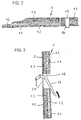
- the sound-insulating cladding according to the invention is preferably designed as an inner end wall cladding 1 for a motor vehicle 2. However, it may in principle also be designed as a sound-insulating lining for other body parts of a motor vehicle, e.g. as bonnet cover or headliner.
- the panel 1 is adapted to the inside contour of an end wall 3, which separates the passenger compartment 4 from the engine compartment 5.
- the panel 1 is self-supporting and is characterized by a relatively low weight. Their total basis weight is, for example, less than 2,500 g / m 2 , preferably less than 2,000 g / m 2 .
- It has a sound absorber layer 1.1, a substantially airtight sound insulation layer 1.2 and an adjoining foam layer 1.3.
- the sound absorber layer 1.1 is formed from a fiber fleece.
- the sound insulation layer 1.2 consists of an integral, at least 0.5 mm thick, skin layer of a soft polyurethane foam layer.
- the sound insulation layer (skin layer) 1.2 is bonded cohesively to the fiber fleece 1.1.
- the non-woven fabric 1.1 is back-foamed with a reaction mixture containing polyol and isocyanate, preferably in one shot ("one-shot process"), ie in a single-stage operation.
- the foam backing of the fibrous web 1.1 is carried out in such a way that foam penetration through the fibrous web is prevented.
- the sound-absorbing properties of the fibrous web 1.1 thus remain substantially unchanged.
- the injection flow direction E of the reaction mixture is aligned parallel to the underside of the fiber fleece 1.1 or to the surface of the lower Häumwerkmaschinehberg.
- the non-woven fabric 1.1 is formed of polyethylene fibers, polypropylene fibers, a mixture of polyethylene and polypropylene fibers, cotton fibers or a mixture of polyethylene and natural fibers. It may in particular be a volume fleece. It has an air permeability in the range of 150 to 2,000 liters / m 2 s (measured at a test pressure of 100 Pa). Its length-related flow resistance is in the range of 5 kNs / m 4 to 40 kNs / m 4 , preferably in the range of 5 kNs / m 4 to 25 kNs / m 4 .
- the fibrous web 1.1 was not subjected to any special mechanical and / or chemical surface treatment, such as impregnation.
- the fiber fleece 1.1 to be foam-backed is cut out, for example, as a two-dimensional punched part from a nonwoven fibrous web. Viewed over the cross section, the nonwoven fabric has a substantially uniform density and a substantially uniform flow resistance. As a non-woven fabric can thus be used in the panel according to the invention, a low-priced standard product.
- the basis weight of the non-woven fabric 1.1 is in the range of 100 g / m 2 to 1,600 g / m 2 , preferably in the range of 100 g / m 2 to 1,200 g / m 2 .
- the layer thickness of the fibrous web 1.1 is for example 2 mm to 30 mm, in particular 5 mm to 20 mm.
- the skin formation of the soft polyurethane foam is used in the reaction of its mixture components in the foaming mold.
- the thickness and density of the insulating layer 1.2 is controlled or influenced by the formulation of the reaction mixture and / or the mold temperature.
- the thickness of the sound insulation layer 1.2 is for example 1 mm to 5 mm.
- Their apparent density is, for example, in the range of 0.08 to 2.0 g / cm 3 , preferably in the range of 0.08 to 1.4 g / cm 3 .
- the bulk density of the foam layer 1.3 is in the range from 0.02 to 0.1 g / cm 3 , for example in the range from 0.02 to 0.06 g / cm 3
- the foam backing of the fibrous web 1.1 can take place both in a closed and in an open foaming tool.
- the production of a lining according to the invention will now be with reference to the FIGS. 4 to 10 explained.
- a multi-part foaming tool 6 is shown schematically.
- Other system elements such as storage tanks, containers with agitator, metering pumps, piping, mixing heads, etc., are not shown for clarity.
- the main components (isocyanate and polyol) of the reaction mixture are transferred from storage tanks to intermediate tanks, brought to the required temperature and fed via metering units a mixing head (not shown) which is connected to one or more sprue openings 7 of the lower Shuumwerkmaschinemaschinemaschine 6.1.
- Filler can be added to the reaction mixture or its main components. Suitable fillers are, for example, barium sulfate and / or chalk. Optionally, however, can be dispensed with filler.
- the filler (BaSO 4 and / or chalk) is optionally combined with CO 2 . By adding CO 2 , the bulk density of the soft foam layer 1.3 can be reduced.
- the foaming tool 6 has a lower mold half 6.1 and an upper mold half 6.2, which together in the closed state of the tool one of to be produced corresponding cavity 8 define.
- the upper mold half 6.2 can be raised and lowered relative to the lower mold half 6.1.
- a blank of a fiber web 1.1 is releasably fixed.
- the blank is produced for example by punching.
- needles for releasable fixing of the fiber fleece 1.1, for example needles, in particular barb elements having needles, Velcro strips, gripping elements or the like may be provided on the underside of the tool half 6.2.
- the introduction of the reaction mixture into the mold cavity 8 takes place via one or more feed channels 9 formed in the lower mold half (mold half) 6.2.
- the respective feed channel is designed such that the injection flow direction E of the reaction mixture is substantially parallel to the underside of the fiber web 1.1 or to the bottom surface 8.1 of the tool cavity is aligned.
- the injection of the reaction mixture into the mold cavity 8 takes place in the opened state of the foaming tool 6.
- the reaction mixture thus does not initially touch the fibrous web 1.1.
- the foaming tool is closed.
- the direct cohesive connection between the reaction mixture and the fiber fleece 1.1 results in the reaction of the reaction mixture, which expands in the cavity 8.
- the fiber fleece 1.1 floats practically on the rising PUR soft foam.
- the foaming tool 6 is provided with a tempering device which comprises separately controllable fluid channels integrated in the tool halves 6.1, 6.2, by means of which predetermined surface regions of the foaming tool 6 delimiting the cavity 8 can be specifically tempered (cooled).
- Temperature control of surface areas of the foaming tool 6 in the present context means a relative cooling of the respective surface areas with respect to the warmer flexible foam reaction mixture.
- the lower die half 6.1 has a group of fluid passages 10 connected to a common fluid supply manifold (not shown) and to a common fluid discharge manifold (not shown).
- the temperature of the fluid supplied to this group of fluid channels is controlled so that the tool surface closest to these fluid channels 10 has a temperature in the range of 50 ° C to 90 ° C, e.g. about 70 ° C ⁇ 15 ° C or there is a temperature in the temperature range.
- the fluid channels 11 integrated in the upper die half 6.2 form a second group of fluid passages which are connected to another common distribution line (not shown) supplying fluid and to another collecting line (not shown) discharging this fluid, the temperature of which Fluid is regulated so that the fluid channels 11 nearest surface of the upper mold half 6.2 a temperature in the range of 15 ° C to 60 ° C, eg about 35 ° C ⁇ 15 ° C or there is a temperature in this temperature range.
- the temperature difference between the cavities limiting surfaces of the tool halves 6.1, 6.2 is at least 15 ° C, preferably at least 25 ° C.
- the foam structure of the flexible foam layer is formed essentially by the resulting in the chemical crosslinking of the reaction mixture propellant gases.
- the optionally added CO 2 supports the foaming process.
- the foaming process in the reaction mixture is suppressed in the region adjoining the cooler tool surface, so that there an integral, substantially non-porous skin 1.2 with a thickness of at least 0 , 5 mm, preferably at least 0.8 mm, more preferably at least 1 mm is produced.
- the skin acts as a sound-insulating layer 1.2. It is preferably airtight or at least substantially airtight.
- the skin 1.2 connects cohesively to the back of the fibrous web 1.1.
- the fiber fleece 1.1 when attached to the foaming tool 6, has a temperature which is considerably below the temperature of the surface of the upper die half 6.1.
- the nonwoven fabric 1.1 is cooled to a temperature in the range of 10 ° C to 15 ° C and fixed in this cooled state at the upper mold half 6.2.
- On the warmer surface of the lower mold half 6.2 forms by the foaming an open-porous sound absorber 1.3, which has an open-pored surface or only a very thin skin 1.4, this thin skin 1.4 but sound-transparent or sound transparent.
- the sound-permeable skin 1.4 has a thickness of less than 400 ⁇ m, preferably less than 250 ⁇ m. It is for example thinner than 150 microns and may also be only partially formed.
- the lining 1 according to the invention has on the edge a flexible sealing lip 12 which can compensate for any manufacturing tolerances that exist and thus ensures a tight adaptation of the lining 1 to adjacent components or body sections (cf. Fig. 2 ).
- fluid channels 13 are provided in the lower mold half 6.1 near the cavity section corresponding to the sealing lip, which are also connected to the fluid distribution line (not shown) associated with the second group of fluid channels 10. The fluid flowing through the fluid channels 10 and 13 thus has the same temperature.
- plunger 14 are also integrated, by means of which the finished molding, so the panel 1 after opening the foaming tool 6 can be ejected.
- FIG. 2 is shown at an opening 15 for a cable or a hose, preferably an elastically expandable spout 16 for sealed passage of the cable or hose line (not shown) on the gullet side of the panel 1, so on the integral, substantially non-porous skin 1.2 having trained page.
- Fig. 3 is a sectional view of a portion of an end wall 3 of a motor vehicle with a breakthrough 3.1 of the end wall cross-pedaling 17 schematically shown.
- a panel 1 according to the invention is arranged, which has an opening 18 for the pedal assembly 17.
- FIGS. 6 and 7 schematically show a further Schwarzumwerkmaschine 6 'for producing a panel according to the invention 1.
- the injection elements 19 each have a tube part 20 which is received axially slidably in a bore 21 of the lower mold half 6.1.
- the tube part 20 is provided with a deflection element 22, via which the reaction mixture containing the polyol and isocyanate is deflected radially relative to the tube part.
- the deflection element 22 ensures that the reaction mixture is not injected substantially perpendicularly onto the fiber fleece 1.1.
- the injection flow direction E of the reaction mixture is aligned substantially parallel to the surface of the fiber fleece 1.1 or to the bottom surface 8.1 of the cavity 8.
- the deflecting element 22 may be formed, for example, in the form of a disk-shaped plate.
- the reaction mixture also comes into direct contact with the fiber fleece 1.1 during injection into the cavity 8 and flows along along the underside of the fiber fleece.
- the injection flow direction E and thus the main flow direction or compressive force of the reaction mixture are directed substantially parallel to the underside of the fiber fleece 1.1.
- essentially a laminar flow of the reaction mixture results parallel to the underside of the fibrous web 1.1.
- the porous sound absorbing layer 1.1 (eg nonwoven fabric) only partially in one or more subregions of the cladding 1 according to the invention. This applies in particular in the case of a breakthrough for the passage of a cable or a hose through the lining 1 according to the invention.
- the reaction mixture can optionally also be injected (injected) perpendicularly against the upper tool half 6.2 into the cavity , In the area of the non-woven fabric 1.1, however, it is not injected perpendicularly to it, but substantially parallel to its underside.
- the opening into the cavity 8 ends of the holes 21 are each extended with a recess 23 into which the deflecting element 22 is retracted after completion of the injection phase.
- the injection elements 19 also serve as a plunger to eject the finished molding from the tool cavity.
- the reaction mixture can also be sprayed or poured into a cavity of a temperature-controlled molding tool (not shown) and a blank of a fiber web 1.1 can then be placed on top of the introduced reaction mixture.
- the upper side of the freshly applied flexible foam and / or the fiber fleece 1.1 are preferably cooled relative to the tempered mold.
- the nonwoven cut is preferably fixed with a holder relative to the ascending reaction mixture.
- the fiber fleece 1.1 thus "floats" during expansion (foaming) of the reaction mixture on the soft foam layer 1.3 and combines during curing of the foam cohesively with the integral, substantially airtight skin 1.2 of the soft foam layer 1.3.
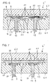
- FIGS. 8 to 10 schematically further multi-part foaming tools for the production of linings according to the invention are shown.
- the sound absorber layer 1.1 formed from a porous absorber, preferably from a nonwoven fabric, in particular a nonwoven web, or from open-celled, air-permeable foam can be arranged over its entire surface or partially on one side of the foamed soundproofing layer 1.2.
- a cladding according to the invention having a sound absorber layer covering only a partial area of the sound insulation layer 1.2 can be produced with a foaming tool 6 ", as is shown by way of example in FIG Fig. 8 outlined.
- the lower mold half 6.1 defines a mold wall (molding surface) 30, in which at least one recess (pocket) 31 is formed for receiving a blank of the porous, air-permeable sound absorber layer 1.1.
- the cavity defined by the recess 31 is substantially completely filled by the absorber blank 1.1 inserted therein.
- a peripheral frame 32 is placed at the edge of the recess 31 and its transition to the mold wall 30 of the mold half 6.1.
- the frame 32 prevents that from being produced the foam layer flows into the cavity 8 of the foaming mold 6 "under the sound absorbing layer 1.1
- the frame 32 covers the edge of the sound absorbing layer 1.1 and extends outwardly beyond the edge of the recess 31.
- the frame 32 is flat and consists for example of It is coated with release agent (anti-adhesive).
- the at least one injection channel 9 (so-called Anschmantician) of the Schwarzumwerkmaschinees 6 "is arranged in relation to the at least one a sound absorbing layer receiving recess 31 so that the reaction mixture R is substantially parallel to the back of the sound absorber layer 1.1 in the Schwarzumwerkmaschine 6" introduced.
- Fig. 8 is indicated by the arrow E that introduced via the injection channel 9 into the cavity reaction mixture R flows substantially parallel to the back of the inserted into the recess 31 absorber blank 1.1.
- the foaming tool further has a vent bore 33 which opens into the cavity 8 and is formed, for example, in the upper die half 6.2.
- a fluid is passed whose temperature is in the range of 50 ° C to 90 ° C, while passing through the fluid channels 11, a fluid whose temperature is in the range of 15 ° C to 60 ° C.
- the temperatures of the fluids are controlled in such a way that a temperature difference of at least 15 ° C., preferably at least 20 ° C., is established between the surfaces of the tool halves 6.1, 6.2 bordering the cavity 8.
- FIG. 9 A foaming tool 6 "'for producing a lining according to the invention is shown, which is intended to have at least one opening for the passage of a pipe and / or a mechanical component, using a blank of a sound absorbing layer 1.1 in which the at least one opening 15' is already cut out ,
- the mold wall 30 delimiting the cavity 8 of the foaming mold is provided with at least one socket-shaped or frustoconical projection 34, which is assigned to the opening 15 'of the sound-absorbing layer 1.1.
- the projection 34 penetrates the opening 15 'of the sound absorber layer 1.1 when it enters the cavity 8 of the foaming tool 6 "'. is inserted.
- the projection 34 has a circumferential undercut, so that it covers the edge of the opening 15 'on the back-foaming of the rear side of the sound absorber layer 1.1 and thus prevents the injected reaction mixture R flows through the opening 15' to the front of the sound absorber layer 1.1.
- the undercut is formed for example by a baffle plate 34.1, which is attached to the outer end face of the projection 34.
- the sound absorber layer 1.1 which preferably consists of an air-permeable nonwoven, covers the mold wall 30 of the mold half 6.1 delimiting the cavity 8 substantially over its entire area.
- the foaming tool 6 "' is in turn provided with ventilation channels 33 which open into the cavity 8 near the outer edge of the inserted sound absorber layer 1.1.
- a further advantageous embodiment of the cladding according to the invention is that only their sound absorbing layer forms a flexible sealing lip 12 '.
- the sound absorber layer 1.1 is embossed edge side, i. permanently condensed. It towers laterally beyond the edge of the foamed sound insulation 1.2.
- the sealing lip 12 ' can extend along the entire circumference or only along one or more sections of the edge of the sound insulation layer 1.2.
- the edge embossing of the sound absorbing layer 1.1 which preferably consists of a thermoplastic nonwoven, is in Fig. 10 shown.
- the upper mold half 6.2 and the lower mold half 6.1 of the foaming mold 6 IV form a clamping region 35 at the edge of the cavity.
- the sound absorber layer 1.1 placed on the lower mold half 6.1 is dimensioned so that its edge is clamped in the clamp region 35 after closing the foaming tool 6 IV ,
- the edge-side clamping of the sound absorber layer 1.1 prevents the injected into the closed cavity reaction mixture flows around the edge of the sound absorber layer 1.1.
- the introduction of the reaction mixture to foam the sound absorber layer 1.1 takes place by means of one or more axially displaceable injection elements 19, the in FIGS.
- the thickness of the air-permeable thermoplastic sound absorbing layer 1.1 is, for example, in the range of 10 mm to 20 mm.
- the thickness of the flexible sealing lip 12 ' is about 2 to 3 mm.
- the foaming tool 6 IV has a clamping device 35 associated with the heating device, with which there compressed edge of the thermoplastic sound absorbing layer 1.1 can be heated to a temperature above 100 ° C, for example to about 120 ° C.
- the heater comprises in the illustrated embodiment, fluid channels 36 in which circulates a suitable liquid, such as an oil. Alternatively, the heater may also include electrical heating elements. Otherwise, the foaming tool 6 IV is in turn provided with fluid channels 10, 11, wherein the temperatures of the fluids flowing therein as described above with reference to Fig. 8 be mentioned.
- the porous absorber 1.1 or an additionally attached cover fleece from a flame retardant nonwoven fabric, preferably made of polyester nonwoven fabric is formed.
- the cladding is preferably equipped so that it has a temperature resistance of at least 150 ° C.
- the panel according to the invention can be used so advantageous in the motor-related area of a motor vehicle or on similarly temperature-stressed areas.
- the embodiment of the invention is not limited to the embodiments described above. Rather, different variants are conceivable that make use of the idea of the invention reproduced in the claims, even if they are fundamentally deviating in design.
- a porous, open-pore foam can also be used as the sound absorber layer.
- the lining 1 according to the invention can, for example, also comprise a plurality of partial sound-insulating regions, i. have a plurality of integral, spaced-apart, substantially non-porous, air-impermeable skin areas, which are arranged selectively on the panel 1 according to the acoustic requirements of the sound insulation.
Landscapes
- Physics & Mathematics (AREA)
- Acoustics & Sound (AREA)
- Engineering & Computer Science (AREA)
- Mechanical Engineering (AREA)
- Multimedia (AREA)
- Vehicle Interior And Exterior Ornaments, Soundproofing, And Insulation (AREA)
- Laminated Bodies (AREA)
- Soundproofing, Sound Blocking, And Sound Damping (AREA)
- Casting Or Compression Moulding Of Plastics Or The Like (AREA)
- Molding Of Porous Articles (AREA)
Claims (19)
- Revêtement léger, d'isolation acoustique (1) pour une pièce de carrosserie d'un véhicule à moteur, en particulier sous forme d'un revêtement léger de paroi avant, comprenant une couche absorbant le bruit (1.1), une couche amortissant le bruit (1.2) étanche à l'air directement reliée à la couche absorbant le bruit (1.1) et une couche de mousse consécutive (1.3), la couche absorbant le bruit (1.1) étant formée d'un absorbeur poreux, de préférence un non tissé fibreux ou une mousse, caractérisé en ce que l'absorbeur poreux (1.1) présente pour une pression test de 100 Pa une perméabilité d'air dans le domaine de 150 à 2.000 litres/m2s, la couche amortissant le bruit (1.2) étant formée par une couche de pellicule intégrale d'au moins 0,5 mm d'épaisseur de la couche de mousse (1.3) et étant reliée par surmoussage de l'absorbeur poreux (1.1) sans pénétration de mousse par liaison de matière à l'absorbeur poreux (1.1).
- Revêtement (1) selon la revendication 1, caractérisé en ce que l'absorbeur poreux (1.1) présente une résistance à l'écoulement relative à la longueur comprise dans le domaine de 5 kNs/m4 à 40 kNs/m4, de préférence dans le domaine de 5 kNs/m4 à 25 kNs/m4
- Revêtement (1) selon la revendication 1 ou 2, caractérisé en ce que l'absorbeur poreux (1.1) présente une densité homogène et/ou une résistance à l'écoulement régulière observée sur sa section transversale.
- Revêtement (1) selon l'une des revendications 1 à 3, caractérisé en ce que l'absorbeur poreux (1.1) présente un grammage de 100 g/m2 à 1.600 g/m2 et/ou compris une épaisseur dans le domaine de 2 mm à 30 mm.
- Revêtement (1) selon l'une des revendications 1 à 4, caractérisé en ce que l'absorbeur poreux (1.1) est composé d'un non tissé fibreux en fibres de polyéthylène, de polypropylène, d'un mélange de fibres de polyéthylène et de polypropylène, de fibres de coton ou un mélange de fibres polyéthylène et de fibres naturels.
- Revêtement (1) selon l'une des revendications 1 à 5, caractérisé en ce que la couche amortissant le bruit (1.2) présente une épaisseur dans le domaine de 1 mm à 5 mm.
- Revêtement (1) selon l'une des revendications 1 à 6, caractérisé en ce que la couche amortissant le bruit (1.2) présente une densité brute dans le domaine de 0,08 à 2,0 g/cm3, de préférence dans le domaine de 0,08 à 1,4 g/cm3.
- Revêtement (1) selon l'une des revendications 1 à 7, caractérisé en ce que la couche amortissant le bruit (1.2) présente localement des zones de surfaces d'épaisseur différentes dont la différence est d'au moins un 1 mm.
- Revêtement (1) selon l'une des revendications 1 à 8, caractérisé en ce que la couche de mousse (1.3) présente une densité brute dans le domaine de 0,02 à 0,06 g/cm3.
- Revêtement (1) selon l'une des revendications 1 à 9, caractérisé en ce que son grammage total est inférieur à 2.500 g/m2, de préférence est inférieur à 2.000 g/m2.
- Procédé pour la fabrication d'un revêtement léger, d'isolation acoustique (1) pour une pièce de carrosserie d'un véhicule à moteur, en particulier sous forme d'un revêtement léger de paroi avant, où une couche poreuse absorbant le bruit (1.1) est directement surmoulé dans un outil de moussage (6, 6') avec un mélange de réaction contenant du polyol et de l'isocyanate, caractérisé en ce qu'on utilise en tant que couche poreuse absorbant le bruit (1.1) un absorbeur qui présente pour une pression test de 100 Pa une perméabilité d'air dans le domaine de 150 à 2.000 litres/m2s, en ce que le mélange de réaction est introduit dans l'outil de moussage parallèlement à la face arrière de la couche absorbant le bruit (1.1) et/ou parallèlement à la surface de fond (8.1) d'une cavité de l'outil de moussage (6, 6'), et en ce qu'une zone prédéterminée partielle de surface de l'outil de moussage (6, 6') est tempérée et/ou pendant l'introduction le rapport de mélange entre le polyol et l'isocyanate est modifiée de sorte qu'il en résulte à partir du mélange de réaction une couche de mousse (1.3) qui présente une couche de pellicule intégrale (1.2) d'au moins 0,5 mm d'épaisseur qui est reliée à la liaison de matière à la couche absorbant le bruit (1.1) sans pénétration de mousse.
- Procédé selon la revendication 11, caractérisé en ce qu'un volume limité du mélange de réaction est introduit à l'outil de moussage (6, 6') de sorte que le mélange de réaction ne touche pas tout d'abord la couche poreuse absorbant le bruit (1.1), la liaison de matière entre le mélange de réaction et la couche poreuse absorbant le bruit (1.1) se réalisant ensuite lors de la réaction du mélange de réaction.
- Procédé selon la revendication 11 ou 12, caractérisé en ce que le surmoussage de la couche poreuse absorbant le bruit (1.1) est effectué dans un outil de moussage ouvert (6).
- Procédé selon la revendication 11 ou 12, caractérisé en ce que le surmoussage de la couche poreuse absorbant le bruit (1.1) est effectué dans un outil de moussage fermé (6').
- Procédé selon la revendication 14, caractérisé en ce que le mélange de réaction est injecté dans l'outil fermé (6') de moussage en utilisant un outil de déviation (22), l'outil de déviation (22) imposant au mélange de réaction une direction d'écoulement d'injection (E) orientée parallèlement à la face arrière de la couche poreuse absorbant le bruit (1.1).
- Procédé selon l'une des revendications 11 à 15, caractérisé en ce que la couche poreuse absorbant le bruit (1.1) utilisée présente observée sur sa section transversale une densité homogène et/ou une résistance d'écoulement régulière.
- Procédé selon l'une des revendications 11 à 16, caractérisé en ce que la couche poreuse absorbant le bruit (1.1) présente une résistance d'écoulement relative à la longueur dans le domaine de 5 kNs/m4 à 40 kNs/m4, de préférence dans le domaine de 5 kNs/m4 à 25 kNs/m4.
- Procédé selon l'une des revendications 11 à 17, caractérisé en ce que la couche poreuse absorbant le bruit (1.1) utilisée présente un grammage de 100 g/m2 à 1.600 g/m2 et/ou une épaisseur dans le domaine de 2 mm à 30 mm.
- Procédé selon l'une des revendications 11 à 18, caractérisé en ce que la couche poreuse absorbant le bruit (1.1) utilisée est composée de fibres de polyéthylène, de polypropylène, d'un mélange de fibres de polyéthylène et de polypropylène, de fibres de coton ou d'un mélange de fibres naturelles et de polyéthylène.
Applications Claiming Priority (2)
| Application Number | Priority Date | Filing Date | Title |
|---|---|---|---|
| DE102007020832A DE102007020832B4 (de) | 2007-05-02 | 2007-05-02 | Leichte, schallisolierende Verkleidung für ein Karosserieteil eines Kraftfahrzeuges und Verfahren zu deren Herstellung |
| PCT/EP2008/054604 WO2008135357A1 (fr) | 2007-05-02 | 2008-04-16 | Revêtement léger d'isolation acoustique pour pièce de carrosserie d'un véhicule à moteur et son procédé de réalisation |
Publications (2)
| Publication Number | Publication Date |
|---|---|
| EP2143098A1 EP2143098A1 (fr) | 2010-01-13 |
| EP2143098B1 true EP2143098B1 (fr) | 2013-12-04 |
Family
ID=39672660
Family Applications (1)
| Application Number | Title | Priority Date | Filing Date |
|---|---|---|---|
| EP08736279.4A Not-in-force EP2143098B1 (fr) | 2007-05-02 | 2008-04-16 | Revêtement léger d'isolation acoustique pour pièce de carrosserie d'un véhicule à moteur et son procédé de réalisation |
Country Status (13)
| Country | Link |
|---|---|
| US (1) | US7980358B2 (fr) |
| EP (1) | EP2143098B1 (fr) |
| JP (1) | JP5319660B2 (fr) |
| KR (1) | KR20100014243A (fr) |
| CN (1) | CN101601085B (fr) |
| BR (1) | BRPI0805831A2 (fr) |
| CA (1) | CA2670401A1 (fr) |
| DE (1) | DE102007020832B4 (fr) |
| IN (1) | IN2009KN02413A (fr) |
| MX (1) | MX2009009554A (fr) |
| RU (1) | RU2456680C2 (fr) |
| TW (1) | TW200904670A (fr) |
| WO (1) | WO2008135357A1 (fr) |
Families Citing this family (46)
| Publication number | Priority date | Publication date | Assignee | Title |
|---|---|---|---|---|
| US20090038875A1 (en) * | 2005-05-12 | 2009-02-12 | Arctic Cat, Inc. | Off-road engine configuration with noise reduction system |
| DE102006009134B4 (de) * | 2006-02-24 | 2016-03-24 | Bayer Materialscience Aktiengesellschaft | Verbessertes Verfahren zur Herstellung einer leichten, schallisolierenden Verkleidung für Kraftfahrzeuge und entsprechende Verkleidung |
| FR2912100B1 (fr) * | 2007-02-06 | 2009-05-08 | Cera | Panneau de protection acoustique pour vehicule automobile comprenant une couche d'etancheite impregnee |
| DE102008062999A1 (de) * | 2008-12-23 | 2010-08-12 | Elringklinger Ag | Trennvorrichtung |
| DE102009020995A1 (de) | 2009-05-12 | 2011-02-10 | Dr. Freist Automotive Bielefeld Gmbh | Leichte, schallisolierende Verkleidung für ein Karosserieteil oder eine Komponente eines Kraftfahrzeugs und Verfahren zu deren Herstellung |
| FR2953786B1 (fr) * | 2009-12-15 | 2012-02-24 | Cera | Panneau de protection acoustique pour vehicule automobile |
| EP2364881B1 (fr) * | 2010-03-09 | 2015-05-13 | Autoneum Management AG | Pièce de garniture d'automobile pour l'isolation sonore et l'absorption |
| DE202010005400U1 (de) * | 2010-05-07 | 2010-07-15 | Recticel N.V. | Elastischer Fahrzeugreifen |
| US8770269B2 (en) | 2010-06-11 | 2014-07-08 | Hs Marston Aerospace Ltd. | Three phase fin surface cooler |
| US8544531B2 (en) | 2010-06-11 | 2013-10-01 | Hs Marston Aerospace Ltd. | Surface cooler with noise reduction |
| DE102010031855A1 (de) * | 2010-07-22 | 2012-01-26 | J. Eberspächer GmbH & Co. KG | Abgasanlage |
| DE102010035431A1 (de) | 2010-08-26 | 2012-03-01 | Entwicklungsgesellschaft für Akustik (EfA) mit beschränkter Haftung | Breitbandiger Schallabsorber |
| FI123952B (fi) * | 2011-01-12 | 2014-01-15 | Acoustic Group Oy | Pinnoite ja sen valmistusmenetelmä |
| DE102011078935A1 (de) | 2011-07-11 | 2013-01-17 | Bayerische Motoren Werke Aktiengesellschaft | Hochabsorptives Schallisolationsbauteil, insbesondere für den Kraftfahrzeuginnenraum |
| DE102012216500A1 (de) * | 2012-09-17 | 2014-03-20 | Hp Pelzer Holding Gmbh | Mehrlagiger gelochter Schallabsorber |
| IN2015DN03907A (fr) | 2012-11-06 | 2015-10-02 | Hyundai Motor Co Ltd | |
| US9139142B2 (en) | 2013-03-15 | 2015-09-22 | Cadillac Products Automotive Company | Three-layer acoustic insulator |
| DE202013012568U1 (de) | 2013-05-07 | 2017-07-17 | Johann Borgers GmbH | Hinterschäumbares Akustikelement eines Kraftfahrzeugkarosserieverkleidungsbauteils |
| DE102013107203A1 (de) * | 2013-07-09 | 2015-01-15 | Dr. Ing. H.C. F. Porsche Aktiengesellschaft | Dachschalen-Aufbau für ein Kraftfahrzeug |
| GB2516489A (en) * | 2013-07-24 | 2015-01-28 | Geko Innovations Ltd | Acoustic Panel |
| FR3012557B1 (fr) * | 2013-10-31 | 2016-01-08 | Cera | Joint d’etancheite acoustique |
| CN103786659B (zh) * | 2014-01-25 | 2015-11-18 | 湖北三环汽车工程塑料有限公司 | 一种复合结构的轻量化隔音垫及其生产方法 |
| US20150232044A1 (en) * | 2014-02-14 | 2015-08-20 | Cadillac Products Automotive Company | Latex impregnated fibrous acoustic insulator |
| DE102014203053A1 (de) * | 2014-02-20 | 2015-08-20 | Volkswagen Aktiengesellschaft | Modul eines Fahrgastraums eines Fahrzeugs |
| US9434325B2 (en) | 2014-04-23 | 2016-09-06 | Toyota Motor Engineering & Manufacturing North America, Inc. | Radiant barrier for automotive vehicle |
| EP3012155A1 (fr) * | 2014-10-20 | 2016-04-27 | Autoneum Management AG | Partie de plancher principal destiné à un petit véhicule utilitaire |
| EP3015314B1 (fr) * | 2014-10-30 | 2017-08-23 | Autoneum Management AG | Pièce de garniture acoustique légère |
| DE102015118967B4 (de) * | 2014-11-06 | 2022-05-25 | Cadillac Products Automotive Company | Schallschutz-Baugruppe mit Schallabdichtung und Verfahren zur Herstellung derselben |
| US9908485B2 (en) * | 2014-11-06 | 2018-03-06 | Cadillac Products Automotive Company | Acoustic barrier assembly with acoustic seal |
| FR3028817B1 (fr) | 2014-11-25 | 2018-03-02 | Autoneum Management Ag. | Piece automobile d'ecrantage acoustique et son procede de fabrication |
| DE102015209105A1 (de) * | 2015-05-19 | 2016-11-24 | Hp Pelzer Holding Gmbh | Leichtes akustisches Bauteil |
| US20160369865A1 (en) * | 2015-06-19 | 2016-12-22 | Ford Global Technologies, Llc | Acoustical Absorber With Integral Fastener |
| US20170030074A1 (en) | 2015-07-30 | 2017-02-02 | Certainteed Corporation | System, method and apparatus for compressed insulation |
| FR3049752B1 (fr) * | 2016-04-05 | 2018-05-11 | Treves Products, Services & Innovation | Procede de fabrication d’un panneau de protection acoustique pour vehicule automobile |
| JP6771029B2 (ja) * | 2016-05-17 | 2020-10-21 | 三井化学株式会社 | シール部材およびその製造方法と乗物用ドアおよび建物用ドア |
| US11104098B2 (en) | 2016-05-31 | 2021-08-31 | Cadillac Products Automotive Company | Fibrous vehicle underbody shield |
| DE102016211687A1 (de) | 2016-06-29 | 2018-01-04 | Volkswagen Aktiengesellschaft | Verfahren zum Herstellen eines schallisolierenden Verkleidungsteils und schallisolierendes Verkleidungsteil |
| US10418017B1 (en) * | 2017-02-28 | 2019-09-17 | Technicon Industries, Inc. | Acoustic insulation with hook and loop fasteners |
| DE102017105679A1 (de) * | 2017-03-16 | 2018-09-20 | Webasto SE | Dachschale mit Akustikdämmschicht |
| CA3053172C (fr) * | 2017-04-03 | 2021-03-30 | Cascade Engineering, Inc. | Silencieux a fibres acoustiques |
| DE102017217083A1 (de) * | 2017-09-26 | 2019-03-28 | Volkswagen Aktiengesellschaft | Schalldämpfungsteil, Verfahren zur Herstellung einer schallgedämmten Karosserie und Kraftfahrzeug |
| US11524430B2 (en) * | 2017-11-29 | 2022-12-13 | Kyoraku Co., Ltd. | Structure, and method for manufacturing same |
| EP3760397A4 (fr) * | 2018-02-28 | 2021-08-11 | Sony Group Corporation | Dispositif d'insonorisation, dispositif robot, procédé et programme de commande de dispositif robot |
| WO2020040908A2 (fr) * | 2018-07-17 | 2020-02-27 | Certainteed Ceilings Corporation | Panneaux acoustiques et procédés de préparation de ceux-ci |
| US12065084B2 (en) | 2018-12-18 | 2024-08-20 | Adler Pelzer Holding Gmbh | Sound insulation element for the firewall of a vehicle body and support element for a sound insulation element of this type |
| CN112319396B (zh) * | 2020-11-27 | 2022-10-21 | 安徽江淮汽车集团股份有限公司 | 一种汽车内前围隔音垫组件及汽车 |
Citations (1)
| Publication number | Priority date | Publication date | Assignee | Title |
|---|---|---|---|---|
| WO2007096427A1 (fr) * | 2006-02-24 | 2007-08-30 | Carcoustics Techconsult Gmbh | Procédé amélioré pour la fabrication d'un revêtement d'isolation phonique léger pour les véhicules automobiles et revêtement correspondant |
Family Cites Families (43)
| Publication number | Priority date | Publication date | Assignee | Title |
|---|---|---|---|---|
| US3816233A (en) * | 1970-10-01 | 1974-06-11 | Specialty Converters | Manufacture of urethane foam sheets |
| US3936555A (en) * | 1972-01-28 | 1976-02-03 | The Fiberwoven Corporation | Filled textile fabric with a density gradient |
| US4101704A (en) * | 1976-04-29 | 1978-07-18 | National Research Development Corporation | Energy absorbing materials |
| DE2735153A1 (de) * | 1977-08-04 | 1979-02-15 | Helmut Pelzer | Spezifisch leichtes feder-masse- system in bekannter weise als doppelmatte ausgebildet |
| US4438166A (en) * | 1983-02-04 | 1984-03-20 | The Celotex Corporation | Structural laminate and method for making same |
| US4476183A (en) * | 1983-11-21 | 1984-10-09 | Monsanto Company | Thermoformable laminate structure with improved acoustical absorption |
| US4529639A (en) * | 1984-06-27 | 1985-07-16 | Collins & Aikman Corporation | Molded foam-backed carpet assembly and method of producing same |
| DE3430775C2 (de) * | 1984-08-21 | 1993-01-28 | Dr. Alois Stankiewicz GmbH, 3101 Adelheidsdorf | Teppichteil, Verfahren zu seiner Herstellung und seine Verwendung |
| CA1322209C (fr) * | 1988-05-18 | 1993-09-14 | Honda Giken Kogyo Kabushiki Kaisha (Also Trading As Honda Motor Co., Ltd .) | Materiau d'insonorisation pour vehicules automobiles |
| JP2513500B2 (ja) * | 1988-10-03 | 1996-07-03 | 株式会社ブリヂストン | 自動車用内装材 |
| US5925207A (en) * | 1991-01-16 | 1999-07-20 | Kasai Kogyo Co., Ltd. | Automotive interior components, and method and device for manufacturing the same |
| RU2081010C1 (ru) * | 1992-05-26 | 1997-06-10 | Научно-технический центр производственного объединения "АвтоВАЗ" | Деталь интерьера салона транспортного средства |
| ATA129392A (de) * | 1992-06-25 | 1999-02-15 | Greiner & Soehne C A | Schaumstoffplatte, insbesondere formteil aus einer oder mehreren schaumstoffplatten |
| JP3488271B2 (ja) * | 1993-09-27 | 2004-01-19 | 三菱化学株式会社 | 吸音材 |
| JP3304264B2 (ja) * | 1996-09-25 | 2002-07-22 | カネボウ株式会社 | 自動車用車体パネルインシュレータ |
| WO1998018656A1 (fr) * | 1996-10-29 | 1998-05-07 | Rieter Automotive (International) Ag | Assemblage de materiaux ultraleger, multifonctionnel et insonorisant |
| US5932331A (en) * | 1998-10-08 | 1999-08-03 | Simco Automotive Trim, Inc. | Automotive trim panel having dual density foam support layer |
| US6669265B2 (en) * | 2000-06-30 | 2003-12-30 | Owens Corning Fiberglas Technology, Inc. | Multidensity liner/insulator |
| US6572723B1 (en) * | 2000-06-30 | 2003-06-03 | Owens Corning Fiberglas Technology, Inc. | Process for forming a multilayer, multidensity composite insulator |
| US6955845B1 (en) * | 2000-06-30 | 2005-10-18 | Owens Corning Fiberglas Technology, Inc. | Acoustical and thermal insulator |
| WO2002059870A1 (fr) * | 2001-01-23 | 2002-08-01 | Kasai Kogyo Co., Ltd. | Materiau insonorise pour vehicule et son procede de fabrication |
| US6846169B2 (en) * | 2001-03-30 | 2005-01-25 | Sumitomo Chemical Company, Ltd. | Mold for producing a multilayer molded article and a method for producing a multilayer molded article |
| DE10143167A1 (de) * | 2001-09-04 | 2003-03-27 | Hp Chem Pelzer Res & Dev Ltd | Wärme- und schalldämmende Verkleidung für den Motorraum von Kraftfahrzeugen |
| US6659223B2 (en) * | 2001-10-05 | 2003-12-09 | Collins & Aikman Products Co. | Sound attenuating material for use within vehicles and methods of making same |
| US6802389B2 (en) * | 2001-12-07 | 2004-10-12 | Collins & Aikman Products Co. | Multi-density sound attenuating laminates and methods of making same |
| JP3656232B2 (ja) * | 2002-03-25 | 2005-06-08 | 河西工業株式会社 | 車両用吸音材 |
| US6695374B1 (en) * | 2002-09-27 | 2004-02-24 | Collins & Aikman Products Co. | Vehicle cockpit assemblies having integrated dash insulators, instrument panels and floor coverings, and methods of installing same within vehicles |
| US7070848B2 (en) * | 2002-10-21 | 2006-07-04 | Cascade Engineering, Inc. | Vehicle acoustic barrier |
| DE10251327A1 (de) * | 2002-11-05 | 2004-05-19 | Hp-Chemie Pelzer Research And Development Ltd. | Verfahren zum Direkthinterschäumen von Absorber-System |
| FR2848904B1 (fr) * | 2002-12-23 | 2006-09-08 | Faurecia Automotive Ind | Procede pour realiser une piece d'insonorisation d'epaisseur variable. |
| US7320739B2 (en) * | 2003-01-02 | 2008-01-22 | 3M Innovative Properties Company | Sound absorptive multilayer composite |
| DE10318136B3 (de) * | 2003-04-17 | 2004-10-07 | Carcoustics Tech Center Gmbh | Aus Korkpartikeln und wärmereaktivem Bindemittel gebildeter poröser Schallabsorber und Verfahren zu dessen Herstellung |
| US7585559B2 (en) * | 2003-06-03 | 2009-09-08 | Intellectual Property Holdings, Llc | Foam barrier heat shield |
| DE10334274B3 (de) * | 2003-07-25 | 2005-03-03 | Carcoustics Tech Center Gmbh | Schallisolierendes Verbundteil und Verfahren zu dessen Herstellung |
| US7318498B2 (en) * | 2004-04-06 | 2008-01-15 | Azdel, Inc. | Decorative interior sound absorbing panel |
| DE202004005948U1 (de) * | 2004-04-13 | 2005-08-25 | Carcoustics Tech Center Gmbh | Sandwichartig aufgebauter Luftschallabsorber |
| JP2006017983A (ja) * | 2004-07-01 | 2006-01-19 | Tokai Rubber Ind Ltd | ダッシュパネル用防音部材 |
| US7566475B2 (en) * | 2004-11-09 | 2009-07-28 | International Automotive Components Group North America, Inc. | Acoustic insulator with controlled airflow resistance and method of making same |
| DE102004054646B4 (de) * | 2004-11-11 | 2008-12-04 | Carcoustics Tech Center Gmbh | Leichte schallisolierende Verkleidung für ein Karosserieteil eines Kraftfahrzeuges und Verfahren zu ihrer Herstellung |
| US20060289231A1 (en) * | 2005-06-28 | 2006-12-28 | Priebe Joseph A | Acoustic absorber/barrier composite |
| DE102005056840B3 (de) | 2005-11-28 | 2007-04-12 | Carcoustics Tech Center Gmbh | Schallisolationsteil und Verfahren zu dessen Herstellung |
| DE202006009245U1 (de) * | 2006-06-09 | 2007-10-11 | Carcoustics Tech Center Gmbh | Luftschall absorbierende Motorraumverkleidung für Kraftfahrzeuge, insbesondere Motorhaubenverkleidung |
| FR2912100B1 (fr) * | 2007-02-06 | 2009-05-08 | Cera | Panneau de protection acoustique pour vehicule automobile comprenant une couche d'etancheite impregnee |
-
2007
- 2007-05-02 DE DE102007020832A patent/DE102007020832B4/de not_active Expired - Fee Related
-
2008
- 2008-04-16 IN IN2413KON2009 patent/IN2009KN02413A/en unknown
- 2008-04-16 WO PCT/EP2008/054604 patent/WO2008135357A1/fr active Application Filing
- 2008-04-16 CN CN2008800011583A patent/CN101601085B/zh not_active Expired - Fee Related
- 2008-04-16 US US12/450,190 patent/US7980358B2/en not_active Expired - Fee Related
- 2008-04-16 BR BRPI0805831-8A patent/BRPI0805831A2/pt not_active IP Right Cessation
- 2008-04-16 EP EP08736279.4A patent/EP2143098B1/fr not_active Not-in-force
- 2008-04-16 MX MX2009009554A patent/MX2009009554A/es active IP Right Grant
- 2008-04-16 KR KR1020097010265A patent/KR20100014243A/ko not_active Application Discontinuation
- 2008-04-16 CA CA002670401A patent/CA2670401A1/fr not_active Abandoned
- 2008-04-16 RU RU2009140409/28A patent/RU2456680C2/ru not_active IP Right Cessation
- 2008-04-16 JP JP2010504627A patent/JP5319660B2/ja not_active Expired - Fee Related
- 2008-05-01 TW TW097116062A patent/TW200904670A/zh unknown
Patent Citations (1)
| Publication number | Priority date | Publication date | Assignee | Title |
|---|---|---|---|---|
| WO2007096427A1 (fr) * | 2006-02-24 | 2007-08-30 | Carcoustics Techconsult Gmbh | Procédé amélioré pour la fabrication d'un revêtement d'isolation phonique léger pour les véhicules automobiles et revêtement correspondant |
Also Published As
| Publication number | Publication date |
|---|---|
| RU2009140409A (ru) | 2011-05-10 |
| US7980358B2 (en) | 2011-07-19 |
| TW200904670A (en) | 2009-02-01 |
| CA2670401A1 (fr) | 2008-11-13 |
| DE102007020832A1 (de) | 2008-11-13 |
| EP2143098A1 (fr) | 2010-01-13 |
| KR20100014243A (ko) | 2010-02-10 |
| US20100065366A1 (en) | 2010-03-18 |
| MX2009009554A (es) | 2009-09-15 |
| JP5319660B2 (ja) | 2013-10-16 |
| IN2009KN02413A (fr) | 2015-08-07 |
| CN101601085B (zh) | 2013-03-13 |
| RU2456680C2 (ru) | 2012-07-20 |
| DE102007020832B4 (de) | 2009-02-26 |
| BRPI0805831A2 (pt) | 2011-08-30 |
| CN101601085A (zh) | 2009-12-09 |
| WO2008135357A1 (fr) | 2008-11-13 |
| JP2010524768A (ja) | 2010-07-22 |
Similar Documents
| Publication | Publication Date | Title |
|---|---|---|
| EP2143098B1 (fr) | Revêtement léger d'isolation acoustique pour pièce de carrosserie d'un véhicule à moteur et son procédé de réalisation | |
| EP1986833B1 (fr) | Procédé amélioré pour la fabrication d'un revêtement d'isolation phonique léger pour les véhicules automobiles et revêtement correspondant | |
| EP1809460B1 (fr) | Revetement insonorisant leger pour piece de carrosserie d'un vehicule automobile, et procede pour le realiser | |
| DE60018334T2 (de) | Fahrzeugdachhimmel und verwandte Artikel | |
| WO2007000225A1 (fr) | Procede de fabrication d'une piece de revetement ou de logement pour un vehicule | |
| DE10334274B3 (de) | Schallisolierendes Verbundteil und Verfahren zu dessen Herstellung | |
| DE3809980A1 (de) | Aufbau zur schallisolation, verfahren zu seiner herstellung und seine verwendung | |
| AT518080A4 (de) | Verfahren zur Herstellung eines Kfz-Innenausstattungsbauteils | |
| EP2251858A1 (fr) | Structure d'isolation sonore | |
| DE102009020995A1 (de) | Leichte, schallisolierende Verkleidung für ein Karosserieteil oder eine Komponente eines Kraftfahrzeugs und Verfahren zu deren Herstellung | |
| DE102005056840B3 (de) | Schallisolationsteil und Verfahren zu dessen Herstellung | |
| EP0993935B1 (fr) | Procédé de fabrication d'un renfort de toit pour véhicules et renfort fabriqué par ce procédé | |
| DE102009017758A1 (de) | Dachhimmelelement für ein Kraftfahrzeug | |
| EP2529916A1 (fr) | Procédé de fabrication d'une pièce de formage contrecollée | |
| DE102009032896A1 (de) | Verkleidungsteil und Verfahren zur Herstellung eines Verkleidungsteils | |
| DE102016015465A1 (de) | Verfahren zum Herstellen eines Sandwichbauteils | |
| DE4224667C2 (de) | Herstellung einer mehrlagigen Wandverkleidung | |
| DE102007015600A1 (de) | Türverkleidung, insbesondere für ein Kraftfahrzeug, und Fertigungsverfahren | |
| EP1391282A2 (fr) | Procédé de production de revêtement pour l'intérieur d'un véhicule | |
| EP1391283A1 (fr) | Procédé de fabrication d'un revêtement intérieur pour véhicules et revêtement intérieur pour véhicules | |
| DE102004031414B4 (de) | Verfahren zur Herstellung eines Innenausstattungssystems | |
| DE102014207948B4 (de) | Verfahren zum stoffschlüssigen Verbinden von Fahrzeugbauteilen | |
| DE102015217100A1 (de) | Kfz-Funktionskomponente mit durch adhäsiven Schaum aufgebrachter Isolationslage | |
| DE10235091C1 (de) | Schallisolierendes Verbundteil und Verfahren zu dessen Herstellung | |
| DE102004004548B4 (de) | Verkleidungselement und Verfahren zu dessen Herstellung |
Legal Events
| Date | Code | Title | Description |
|---|---|---|---|
| PUAI | Public reference made under article 153(3) epc to a published international application that has entered the european phase |
Free format text: ORIGINAL CODE: 0009012 |
|
| 17P | Request for examination filed |
Effective date: 20090417 |
|
| AK | Designated contracting states |
Kind code of ref document: A1 Designated state(s): AT BE BG CH CY CZ DE DK EE ES FI FR GB GR HR HU IE IS IT LI LT LU LV MC MT NL NO PL PT RO SE SI SK TR |
|
| RIN1 | Information on inventor provided before grant (corrected) |
Inventor name: SOLTAU, DIRK Inventor name: HANSEN, MICHAEL Inventor name: ULBRICH, DAGMAR Inventor name: GROSS, THOMAS |
|
| DAX | Request for extension of the european patent (deleted) | ||
| 17Q | First examination report despatched |
Effective date: 20110421 |
|
| RAP1 | Party data changed (applicant data changed or rights of an application transferred) |
Owner name: BAYER INTELLECTUAL PROPERTY GMBH Owner name: CARCOUSTICS TECHCONSULT GMBH |
|
| GRAP | Despatch of communication of intention to grant a patent |
Free format text: ORIGINAL CODE: EPIDOSNIGR1 |
|
| INTG | Intention to grant announced |
Effective date: 20130624 |
|
| GRAS | Grant fee paid |
Free format text: ORIGINAL CODE: EPIDOSNIGR3 |
|
| GRAA | (expected) grant |
Free format text: ORIGINAL CODE: 0009210 |
|
| AK | Designated contracting states |
Kind code of ref document: B1 Designated state(s): AT BE BG CH CY CZ DE DK EE ES FI FR GB GR HR HU IE IS IT LI LT LU LV MC MT NL NO PL PT RO SE SI SK TR |
|
| REG | Reference to a national code |
Ref country code: GB Ref legal event code: FG4D Free format text: NOT ENGLISH |
|
| REG | Reference to a national code |
Ref country code: CH Ref legal event code: EP |
|
| REG | Reference to a national code |
Ref country code: IE Ref legal event code: FG4D Free format text: LANGUAGE OF EP DOCUMENT: GERMAN Ref country code: AT Ref legal event code: REF Ref document number: 643805 Country of ref document: AT Kind code of ref document: T Effective date: 20140115 |
|
| REG | Reference to a national code |
Ref country code: DE Ref legal event code: R096 Ref document number: 502008011027 Country of ref document: DE Effective date: 20140130 |
|
| REG | Reference to a national code |
Ref country code: NL Ref legal event code: VDEP Effective date: 20131204 |
|
| PG25 | Lapsed in a contracting state [announced via postgrant information from national office to epo] |
Ref country code: LT Free format text: LAPSE BECAUSE OF FAILURE TO SUBMIT A TRANSLATION OF THE DESCRIPTION OR TO PAY THE FEE WITHIN THE PRESCRIBED TIME-LIMIT Effective date: 20131204 Ref country code: NO Free format text: LAPSE BECAUSE OF FAILURE TO SUBMIT A TRANSLATION OF THE DESCRIPTION OR TO PAY THE FEE WITHIN THE PRESCRIBED TIME-LIMIT Effective date: 20140304 Ref country code: HR Free format text: LAPSE BECAUSE OF FAILURE TO SUBMIT A TRANSLATION OF THE DESCRIPTION OR TO PAY THE FEE WITHIN THE PRESCRIBED TIME-LIMIT Effective date: 20131204 Ref country code: SE Free format text: LAPSE BECAUSE OF FAILURE TO SUBMIT A TRANSLATION OF THE DESCRIPTION OR TO PAY THE FEE WITHIN THE PRESCRIBED TIME-LIMIT Effective date: 20131204 Ref country code: NL Free format text: LAPSE BECAUSE OF FAILURE TO SUBMIT A TRANSLATION OF THE DESCRIPTION OR TO PAY THE FEE WITHIN THE PRESCRIBED TIME-LIMIT Effective date: 20131204 Ref country code: FI Free format text: LAPSE BECAUSE OF FAILURE TO SUBMIT A TRANSLATION OF THE DESCRIPTION OR TO PAY THE FEE WITHIN THE PRESCRIBED TIME-LIMIT Effective date: 20131204 |
|
| REG | Reference to a national code |
Ref country code: LT Ref legal event code: MG4D |
|
| PG25 | Lapsed in a contracting state [announced via postgrant information from national office to epo] |
Ref country code: LV Free format text: LAPSE BECAUSE OF FAILURE TO SUBMIT A TRANSLATION OF THE DESCRIPTION OR TO PAY THE FEE WITHIN THE PRESCRIBED TIME-LIMIT Effective date: 20131204 Ref country code: CY Free format text: LAPSE BECAUSE OF FAILURE TO SUBMIT A TRANSLATION OF THE DESCRIPTION OR TO PAY THE FEE WITHIN THE PRESCRIBED TIME-LIMIT Effective date: 20131204 |
|
| PG25 | Lapsed in a contracting state [announced via postgrant information from national office to epo] |
Ref country code: EE Free format text: LAPSE BECAUSE OF FAILURE TO SUBMIT A TRANSLATION OF THE DESCRIPTION OR TO PAY THE FEE WITHIN THE PRESCRIBED TIME-LIMIT Effective date: 20131204 Ref country code: IS Free format text: LAPSE BECAUSE OF FAILURE TO SUBMIT A TRANSLATION OF THE DESCRIPTION OR TO PAY THE FEE WITHIN THE PRESCRIBED TIME-LIMIT Effective date: 20140404 |
|
| PG25 | Lapsed in a contracting state [announced via postgrant information from national office to epo] |
Ref country code: PT Free format text: LAPSE BECAUSE OF FAILURE TO SUBMIT A TRANSLATION OF THE DESCRIPTION OR TO PAY THE FEE WITHIN THE PRESCRIBED TIME-LIMIT Effective date: 20140404 Ref country code: RO Free format text: LAPSE BECAUSE OF FAILURE TO SUBMIT A TRANSLATION OF THE DESCRIPTION OR TO PAY THE FEE WITHIN THE PRESCRIBED TIME-LIMIT Effective date: 20131204 Ref country code: SK Free format text: LAPSE BECAUSE OF FAILURE TO SUBMIT A TRANSLATION OF THE DESCRIPTION OR TO PAY THE FEE WITHIN THE PRESCRIBED TIME-LIMIT Effective date: 20131204 Ref country code: PL Free format text: LAPSE BECAUSE OF FAILURE TO SUBMIT A TRANSLATION OF THE DESCRIPTION OR TO PAY THE FEE WITHIN THE PRESCRIBED TIME-LIMIT Effective date: 20131204 Ref country code: ES Free format text: LAPSE BECAUSE OF FAILURE TO SUBMIT A TRANSLATION OF THE DESCRIPTION OR TO PAY THE FEE WITHIN THE PRESCRIBED TIME-LIMIT Effective date: 20131204 Ref country code: CZ Free format text: LAPSE BECAUSE OF FAILURE TO SUBMIT A TRANSLATION OF THE DESCRIPTION OR TO PAY THE FEE WITHIN THE PRESCRIBED TIME-LIMIT Effective date: 20131204 |
|
| REG | Reference to a national code |
Ref country code: DE Ref legal event code: R097 Ref document number: 502008011027 Country of ref document: DE |
|
| PLBE | No opposition filed within time limit |
Free format text: ORIGINAL CODE: 0009261 |
|
| STAA | Information on the status of an ep patent application or granted ep patent |
Free format text: STATUS: NO OPPOSITION FILED WITHIN TIME LIMIT |
|
| PG25 | Lapsed in a contracting state [announced via postgrant information from national office to epo] |
Ref country code: DK Free format text: LAPSE BECAUSE OF FAILURE TO SUBMIT A TRANSLATION OF THE DESCRIPTION OR TO PAY THE FEE WITHIN THE PRESCRIBED TIME-LIMIT Effective date: 20131204 |
|
| 26N | No opposition filed |
Effective date: 20140905 |
|
| PG25 | Lapsed in a contracting state [announced via postgrant information from national office to epo] |
Ref country code: LU Free format text: LAPSE BECAUSE OF FAILURE TO SUBMIT A TRANSLATION OF THE DESCRIPTION OR TO PAY THE FEE WITHIN THE PRESCRIBED TIME-LIMIT Effective date: 20140416 Ref country code: MC Free format text: LAPSE BECAUSE OF FAILURE TO SUBMIT A TRANSLATION OF THE DESCRIPTION OR TO PAY THE FEE WITHIN THE PRESCRIBED TIME-LIMIT Effective date: 20131204 |
|
| REG | Reference to a national code |
Ref country code: CH Ref legal event code: PL |
|
| REG | Reference to a national code |
Ref country code: DE Ref legal event code: R097 Ref document number: 502008011027 Country of ref document: DE Effective date: 20140905 |
|
| REG | Reference to a national code |
Ref country code: IE Ref legal event code: MM4A |
|
| PG25 | Lapsed in a contracting state [announced via postgrant information from national office to epo] |
Ref country code: CH Free format text: LAPSE BECAUSE OF NON-PAYMENT OF DUE FEES Effective date: 20140430 Ref country code: LI Free format text: LAPSE BECAUSE OF NON-PAYMENT OF DUE FEES Effective date: 20140430 |
|
| PG25 | Lapsed in a contracting state [announced via postgrant information from national office to epo] |
Ref country code: SI Free format text: LAPSE BECAUSE OF FAILURE TO SUBMIT A TRANSLATION OF THE DESCRIPTION OR TO PAY THE FEE WITHIN THE PRESCRIBED TIME-LIMIT Effective date: 20131204 |
|
| PG25 | Lapsed in a contracting state [announced via postgrant information from national office to epo] |
Ref country code: IT Free format text: LAPSE BECAUSE OF FAILURE TO SUBMIT A TRANSLATION OF THE DESCRIPTION OR TO PAY THE FEE WITHIN THE PRESCRIBED TIME-LIMIT Effective date: 20131204 |
|
| REG | Reference to a national code |
Ref country code: FR Ref legal event code: PLFP Year of fee payment: 8 |
|
| PG25 | Lapsed in a contracting state [announced via postgrant information from national office to epo] |
Ref country code: IE Free format text: LAPSE BECAUSE OF NON-PAYMENT OF DUE FEES Effective date: 20140416 |
|
| REG | Reference to a national code |
Ref country code: AT Ref legal event code: MM01 Ref document number: 643805 Country of ref document: AT Kind code of ref document: T Effective date: 20140416 |
|
| PGFP | Annual fee paid to national office [announced via postgrant information from national office to epo] |
Ref country code: GB Payment date: 20150424 Year of fee payment: 8 |
|
| PG25 | Lapsed in a contracting state [announced via postgrant information from national office to epo] |
Ref country code: AT Free format text: LAPSE BECAUSE OF NON-PAYMENT OF DUE FEES Effective date: 20140416 |
|
| PGFP | Annual fee paid to national office [announced via postgrant information from national office to epo] |
Ref country code: FR Payment date: 20150424 Year of fee payment: 8 |
|
| REG | Reference to a national code |
Ref country code: DE Ref legal event code: R082 Ref document number: 502008011027 Country of ref document: DE Representative=s name: COHAUSZ & FLORACK PATENT- UND RECHTSANWAELTE P, DE Ref country code: DE Ref legal event code: R081 Ref document number: 502008011027 Country of ref document: DE Owner name: COVESTRO DEUTSCHLAND AG, DE Free format text: FORMER OWNERS: BAYER INTELLECTUAL PROPERTY GMBH, 40789 MONHEIM, DE; CARCOUSTICS TECHCONSULT GMBH, 51381 LEVERKUSEN, DE Ref country code: DE Ref legal event code: R081 Ref document number: 502008011027 Country of ref document: DE Owner name: CARCOUSTICS TECHCONSULT GMBH, DE Free format text: FORMER OWNERS: BAYER INTELLECTUAL PROPERTY GMBH, 40789 MONHEIM, DE; CARCOUSTICS TECHCONSULT GMBH, 51381 LEVERKUSEN, DE |
|
| REG | Reference to a national code |
Ref country code: GB Ref legal event code: 732E Free format text: REGISTERED BETWEEN 20160303 AND 20160309 |
|
| PG25 | Lapsed in a contracting state [announced via postgrant information from national office to epo] |
Ref country code: MT Free format text: LAPSE BECAUSE OF FAILURE TO SUBMIT A TRANSLATION OF THE DESCRIPTION OR TO PAY THE FEE WITHIN THE PRESCRIBED TIME-LIMIT Effective date: 20131204 |
|
| REG | Reference to a national code |
Ref country code: FR Ref legal event code: TQ Owner name: CARCOUSTICS TECHCONSULT GMBH, DE Effective date: 20160411 Ref country code: FR Ref legal event code: TP Owner name: CARCOUSTICS TECHCONSULT GMBH, DE Effective date: 20160411 |
|
| PG25 | Lapsed in a contracting state [announced via postgrant information from national office to epo] |
Ref country code: BG Free format text: LAPSE BECAUSE OF FAILURE TO SUBMIT A TRANSLATION OF THE DESCRIPTION OR TO PAY THE FEE WITHIN THE PRESCRIBED TIME-LIMIT Effective date: 20131204 |
|
| PG25 | Lapsed in a contracting state [announced via postgrant information from national office to epo] |
Ref country code: GR Free format text: LAPSE BECAUSE OF FAILURE TO SUBMIT A TRANSLATION OF THE DESCRIPTION OR TO PAY THE FEE WITHIN THE PRESCRIBED TIME-LIMIT Effective date: 20140305 |
|
| PG25 | Lapsed in a contracting state [announced via postgrant information from national office to epo] |
Ref country code: TR Free format text: LAPSE BECAUSE OF FAILURE TO SUBMIT A TRANSLATION OF THE DESCRIPTION OR TO PAY THE FEE WITHIN THE PRESCRIBED TIME-LIMIT Effective date: 20131204 Ref country code: BE Free format text: LAPSE BECAUSE OF FAILURE TO SUBMIT A TRANSLATION OF THE DESCRIPTION OR TO PAY THE FEE WITHIN THE PRESCRIBED TIME-LIMIT Effective date: 20140430 Ref country code: HU Free format text: LAPSE BECAUSE OF FAILURE TO SUBMIT A TRANSLATION OF THE DESCRIPTION OR TO PAY THE FEE WITHIN THE PRESCRIBED TIME-LIMIT; INVALID AB INITIO Effective date: 20080416 |
|
| GBPC | Gb: european patent ceased through non-payment of renewal fee |
Effective date: 20160416 |
|
| REG | Reference to a national code |
Ref country code: FR Ref legal event code: ST Effective date: 20161230 |
|
| PG25 | Lapsed in a contracting state [announced via postgrant information from national office to epo] |
Ref country code: FR Free format text: LAPSE BECAUSE OF NON-PAYMENT OF DUE FEES Effective date: 20160502 Ref country code: GB Free format text: LAPSE BECAUSE OF NON-PAYMENT OF DUE FEES Effective date: 20160416 |
|
| PGFP | Annual fee paid to national office [announced via postgrant information from national office to epo] |
Ref country code: DE Payment date: 20210420 Year of fee payment: 14 |
|
| REG | Reference to a national code |
Ref country code: DE Ref legal event code: R119 Ref document number: 502008011027 Country of ref document: DE |
|
| PG25 | Lapsed in a contracting state [announced via postgrant information from national office to epo] |
Ref country code: DE Free format text: LAPSE BECAUSE OF NON-PAYMENT OF DUE FEES Effective date: 20221103 |