EP2141284A2 - Schaberklingenhaltevorrichtung - Google Patents
Schaberklingenhaltevorrichtung Download PDFInfo
- Publication number
- EP2141284A2 EP2141284A2 EP09162553A EP09162553A EP2141284A2 EP 2141284 A2 EP2141284 A2 EP 2141284A2 EP 09162553 A EP09162553 A EP 09162553A EP 09162553 A EP09162553 A EP 09162553A EP 2141284 A2 EP2141284 A2 EP 2141284A2
- Authority
- EP
- European Patent Office
- Prior art keywords
- cover plate
- clamping
- holding device
- blade holding
- air hose
- Prior art date
- Legal status (The legal status is an assumption and is not a legal conclusion. Google has not performed a legal analysis and makes no representation as to the accuracy of the status listed.)
- Granted
Links
Images


Classifications
-
- D—TEXTILES; PAPER
- D21—PAPER-MAKING; PRODUCTION OF CELLULOSE
- D21G—CALENDERS; ACCESSORIES FOR PAPER-MAKING MACHINES
- D21G3/00—Doctors
- D21G3/005—Doctor knifes
Definitions
- the invention relates to a doctor blade holding device, which has a bottom part, a cover plate, a pivot bearing, finger devices and at least one positioned between the bottom part and the cover plate air hose.
- Such a doctor blade holding device can be used, for example, in a paper mill in papermaking or in the steel industry. It serves to receive a scraper blade for the purpose of even contact with a rotating roller or roller in order to clean the surface during operation.
- a roller may have a width of several meters.
- the scraper blade provided for cleaning such a roller must rest over the entire length of the roller as uniformly as possible at a predetermined angle to the roller. To accomplish this, the doctor blade is generally applied to the roller at a relatively high pressure.
- the cover plate can be removed after a release of one or more screws from the bottom part, for example, to perform service work on the doctor blade holding device.
- the cover plate is removed from the bottom part, the air tubing or tubes remain in the bottom part and then have to be removed from the bottom part within the scope of an additional work step.
- This extra step is in many Cases cumbersome due to the structural conditions of the respective paper machine. For example, an operator must use a ladder in the presence of a tight installation situation, the air hose from the bottom part to solve. Care must be taken to ensure that the air hose does not drop uncontrollably after loosening and causes damage or is itself damaged, for example, by being in contact with hot parts of the paper machine.
- doctor blade holders or the air hoses are positioned without attachment between the bottom part and the cover plate. In such doctor blade holders or the air hoses can fall uncontrollably when removing the cover plate from the bottom part, so that here too damage may occur or increased care is necessary to prevent such damage.
- a doctor blade holding apparatus which has a bottom part, a cover plate, a pivot bearing, finger devices and an air hose positioned between the bottom part and the cover plate.
- the bottom part designated there as the base plate and the cover plate can be pivoted relative to one another about an axis formed by a bearing tube.
- Finger devices are attached to the cover plate in the front area of the cover plate.
- the bearing tube is part of the base plate and is arranged in the finger device end region facing the base plate.
- a device for holding a doctor blade which has a bottom plate and a cover plate.
- the bottom plate and the cover plate are connected to each other via a pivot bearing.
- To attach the squeegee to the cover plate are holding fingers intended.
- In the pivot bearing is a pin hinge, which has several bearing blocks and associated journal blocks.
- In the space between the bottom plate and the cover plate inflatable pressure hoses are provided, by means of one of these pressure hoses, the cover plate can be pressurized, so that the doctor blade is pressed onto the surface of the roller. By means of the other pressure hose, a return of the cover plate is brought about.
- the object of the invention is to provide a doctor blade holding device whose service friendliness is increased.
- the advantages of the invention are in particular that when removing the cover plate from the bottom part of the scraper blade holding device or the air hoses entrained and thus defined and quickly removed from the bottom part. As a result, additional work steps are saved and it is achieved in comparison to the prior art, a time savings. Service work can be done faster overall, which reduces the downtime, for example, a paper machine. In addition, damage caused by the possible uncontrolled dropping of an air hose or several air hoses is also avoided. All this greatly increases the serviceability of a doctor blade holder.
- the invention relates to a doctor blade holding device, which has a bottom part, a cover plate, a pivot bearing, finger devices and at least one positioned between the bottom part and the cover plate air hose, wherein the air hose is fixed to the cover plate.
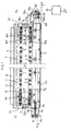
- FIG. 1 shows a sketch of a plan view of such a doctor blade holding device.
- the drive side TS of the device is located on the left side of FIG. 1 , the leader page FS on the right side of FIG. 1 ,
- the cover plate 1 of the device can be seen, which in practice For example, may have a length of 6 m and a width of 20 cm.
- the cover plate 1 has longitudinal sides L1 and L2 and narrow sides S1 and S2.
- trough-shaped bottom part 2 is a in the FIG. 1 Dashed line indicated air hose 3 positioned.
- a plurality of fastening screws 4 is provided, which are passed through the cover plate 1 and in their entirety form a longitudinally extending in the longitudinal direction of the cover plate 1 first row of screws.
- two of these screws 4 are provided for fastening a short square tube 6 to the cover plate 1, wherein these square tubes in the FIG. 1 located below the cover plate 1 and together with a rotatably mounted within the square tubes, firmly connected to the bottom part bearing tube form a pivot bearing.
- cover plate 1 a plurality of further fastening screws 5 are provided, which are also passed through the cover plate 1.
- the fastening screws 5 in their entirety form a second row of screws extending in the longitudinal direction of the cover plate 1.
- two of these screws 5 are provided for fastening a finger device 7 on the cover plate 1, wherein these finger devices in the FIG. 1 located below the cover plate 1.
- These finger devices 7 serve to receive a scraper blade 8, this scraper blade 8 being supported both on the finger devices 7 and on the cover plate 1.
- the air hose 3 is fixed to the cover plate 1.
- a fixed to the cover plate 1 clamping device is provided.
- This clamping device has two clamping units 9 and 10.
- the clamping unit 9 is fixed in the region of the narrow side S1 of the cover plate 1 at this.
- the clamping unit 10 is attached in the region of the narrow side S2 of the cover plate 1 at this.
- the clamping unit 9 has two jaws 9 a and 9 b, wherein in the FIG. 1 the jaws 9 is arranged on the top and the jaws 9b below the jaw 9a. Between these two jaws 9a and 9b, the air hose 3 is clamped such that it is hermetically sealed during operation, is held in the correct position and is subtracted from the bottom part 2 together with the cover plate 1 when the cover plate 1 is removed wherein this removal of the cover plate 1 from the bottom part 2 takes place in the longitudinal direction of the cover plate 1, in particular in the direction of the driver side FS.
- the jaws 9a and 9b are respectively provided with bolt holes 9c through which screws are rotatable to effect the aforementioned tightening.
- the upper jaw 9a is connected by means of a connecting web 9d with a fastening region 9e of the clamping unit 9, whereby the fastening web 9d can be welded onto the fastening region 9e and the clamping jaws 9a, respectively.
- the clamping unit 9 is screwed in its fastening region 9e with the cover plate 1.
- the attachment portion 9e in the longitudinal direction of Cover plate 1 extending recesses 9f and 9g.
- steps 9h, 9i, 9j, 9k are provided, which also extend in the longitudinal direction of the cover plate 1.
- screws 11 are screwed through the cover plate 1 in such a way that, when the clamping unit 9 is screwed to the cover plate 1, said steps serve as a bearing surface for the underside of the screw heads of the screws 11.
- the height of the mounting portion 9e is selected to be greater than or equal to the sum of the height of a step and the height of a screw head.
- the screws 11 are not only used to firmly connect the mounting portion 9e of the clamping unit 9 with the cover plate 1, but further to also attach the finger devices 7 provided in this region of the cover plate to the cover plate.
- the fastening region 9e of the clamping unit 9 is provided with an auxiliary device 12 in its upper region facing away from the cover plate 1, which can be welded onto the upper side of the fastening region 9e.
- this auxiliary device is an approximately cubic metal block, which has a continuous, provided with an internal thread bore 12a in its central region. Through this hole 12a, a threaded rod can be screwed, which together with the auxiliary device 12 serves as insertion or removal aid for the cover plate 1 and attached to this air hose 3.
- the clamping unit 10 which is fastened in the region of the narrow side S2 of the cover plate 1, has a clamping jaw 10a, a further clamping jaw 10b, screw holes 10c, a fastening region 10e, a Recess 10f, a recess 10g and stages 10h, 10i, 10j and 10k on.
- the jaw 10a is disposed on the top and the jaws 10b below the jaw 10a.
- the jaws 10a and 10b are respectively provided with screw holes 10c through which screws are rotatable to fix the two jaws to each other.
- the upper jaw 10a is fixedly connected on its underside to the fastening region 10e of the clamping unit 10, preferably welded.
- the clamping jaw 10b has in its middle region a through hole 101, through which an air connection pipe 10m is guided. On the end of this air connection pipe 10m, which in the FIG. 1 is arranged to the left of the jaws 10b, the right end portion of the air tube 3 is attached. A firm connection of the right end region of the air hose 3 to the end region of the air connection pipe 10m is achieved by clamping the end region of the air hose 3 on the air connection pipe 10m by means of a clamping collar 10n.
- the clamping unit 10 is bolted to the cover plate 1 in its fastening region 10e.
- the fastening region 10e has recesses 10f and 10g extending in the longitudinal direction of the cover plate 1.
- the stages 10h, 10i, 10j, 10k are provided, which also extend in the longitudinal direction of the cover plate 1.
- screws 13 are screwed through the cover plate 1 in such a way that, when the clamping unit 10 is screwed to the cover plate 1, said steps serve as a bearing surface for the underside of the screw heads of the screws 13.
- the height of the attachment portion 10e is selected to be greater than or equal to the sum of the height of a step and the height of a screw head is.
- the fastening region 10e of the clamping unit 10 is provided with an auxiliary device 14 in its upper region facing away from the cover plate 1, which can be welded onto the upper side of the fastening region 10e.
- This auxiliary device is an approximately cube-shaped metal block, which has a continuous, provided with an internal thread bore 14a in its central region. Through this hole 14a, a threaded rod can be screwed, which together with the auxiliary device 14 serves as Einschiebe- or removal aid for the cover plate 1 and attached to this air hose 3.
- a scraper blade holding device is further provided with a control unit 21, which ensures that before removing the cover plate 1 together with the attached air hose 3 in the air hose 3, a vacuum is formed.
- a control unit 21 which ensures that before removing the cover plate 1 together with the attached air hose 3 in the air hose 3, a vacuum is formed.
- This has the advantage that the air tube 3 is contracted or flat, so that it has no contact with the bottom part or other, connected to the bottom part of the doctor blade holding device when removing the cover plate 1. The removal of the cover plate 1 together with the attached air hose 3 can thus be done without friction and is considerably easier.
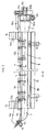
- FIG. 2 shows a sectional view of the in the FIG. 1 shown doctor blade holding device along the section line AA. From the FIG. 2 are beyond the already on the basis of FIG. 1 particular components described Also, the bottom part 2 and an adapter bar 15 can be seen, wherein the bottom part 2 is connected to the adapter bar 15 by means of screws 16 which are guided by a spacer element 19. In particular, goes from the FIG. 2 also shows that the air hose 3 is positioned between the cover plate 1 and the bottom part 2.
- FIG. 3 shows a drive side view of the in the FIG. 1 shown doctor blade holding device. Also from this figure it can be seen that on the drive side narrow side of the cover plate 1, a clamping unit 9 is secured by screws 11 to the cover plate 1, wherein by means of one of these screws 11 also one of the finger devices 7 is fixed to the cover plate and wherein by means of the other Screw 11 in addition, the square tube 6 is attached to the cover plate 1. Between the cover plate 1 and the finger device 7, the scraper blade 8 is positioned, which rests in operation on the roller to be cleaned and abschabt located on a rotation of the roller on the roller residues.
- the bottom part 2 is trough-shaped.
- the bottom part 2 is spaced in its interior from the air hose 3 by the spacer element 19 and contacted in its outer region with the adapter bar 15, wherein the spacer element 19, the bottom part 2 and the adapter bar 15 are screwed together by means of a screw 16.
- the doctor blade 8 facing the end wall of the bottom part 2 is tubular in its end portion 2, said tubular end portion 2a is mounted rotatably within the attached to the cover plate 1 square tube 6.
- sealing plates 17 and 18 are provided.
- the sealing plate 17 extends in its one end region between the bottom part 2 and the adapter bar 15 and is connected by the screw 16 fixed to the bottom part 2.
- the other, free end portion of the seal plate 17 is resiliently against the cover plate 1.
- the sealing plate 18 is screwed to the cover plate 1 and is in its other end resiliently on the doctor blade 8 facing away from the end wall of the bottom part 2.
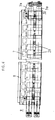
- FIG. 4 shows a sketch of a plan view of a doctor blade holding device according to a second embodiment of the invention.
- the in the FIG. 4 Schaberklingenhaltevorcardi shown largely agrees with the in the FIG. 1
- the scraper blade holding device shown differs, but differs therefrom by a differently realized fastening of the clamping units 9 and 10 on the cover plate 1.
- the first clamping unit 9 is fixed in an end region of the longitudinal side L2 of the cover plate 1 at this and the second clamping unit 10 in the other end region of the longitudinal side L2 of the cover plate 1 attached thereto.
- the clamping unit 10 in the in FIG. 4 shown top view the shape of the letter 1, wherein the two in the FIG. 4 at right angles to the longitudinal axis of the cover plate 1 extending leg connecting middle leg of the clamping unit 10 parallel to the longitudinal side L2 of the cover plate 1 extends.
- the clamping unit 9 has in the in FIG. 4 shown top view the shape of the mirrored letter 1, the two in the FIG. 4 Middle leg of the clamping unit 9 connecting at right angles to the longitudinal direction of the cover plate 1 also runs parallel to the longitudinal side L2 of the cover plate and in alignment with the middle leg of the clamping unit 10.
- FIG. 5 shows a sectional view of a doctor blade holding device according to a third embodiment of the invention.
- the in the FIG. 5 Schaberklingenhaltevorcardi shown largely agrees with the in the FIG. 2
- the scraper blade holding device shown in FIG. 1 differs from it, but differs from it by another embodiment of the on the left side of the FIG. 5 provided clamping unit 9.
- the clamping unit 9 is formed in this third embodiment similar to that on the right side of FIG. 5 In particular, it has clamping jaws 9a and 9b, which are fastened to each other by means of a screw guided through a screw hole 9c.
- the clamping jaw 9b has in its central region a through hole 91 through which an air connection pipe 9m is guided.
- this air connection pipe 9m On the end of this air connection pipe 9m, which in the FIG. 5 is arranged to the right of the jaws 9b, the left end portion of the air hose 3 is attached.
- a firm connection of the left end portion of the air hose 3 with the right end portion of the air connection pipe 9m is achieved in that the left end portion of the air hose 3 is clamped by means of a clamping sleeve 9n on the air connection pipe 9m.
- the air hose 3 is clamped in its two end regions by means of a respective clamping sleeve on an air connection pipe.
- the air supply into the air hose 3 takes place through the air connection pipe 10m.
- the air connection pipe 9m is closed by means of a closure element 9o, so that the respective desired pressure can build up in the air hose 3.
- the FIG. 6 shows a sketch of a plan view of a doctor blade holding device according to a fourth embodiment of the invention.
- the doctor blade holding device comprises two air hoses 3a and 3b, one of which in the FIG. 6 is arranged below the pivot bearing 20 and the other above the pivot bearing 20.
- the pivot bearing 20 is designed as a journal hinge, which has a plurality of bearing blocks and associated journal blocks.
- the first clamping unit 9 serves to clamp the first end region of the first air hose 3a and the first end region of the second air hose 3b.
- the second clamping unit 10 serves to clamp the second end region of the first air hose 3a and the second end region of the second air hose 3b.
- the first clamping unit 9 has two jaws for each of the air hoses, between which the first end region of the respective air hose is clamped.
- the second clamping unit 10 has a clamping sleeve for each of the air hoses, by means of which the second end region of the respective air hose is clamped on a respectively associated air connection pipe.
Landscapes
- Paper (AREA)
- Jigs For Machine Tools (AREA)
- Gripping Jigs, Holding Jigs, And Positioning Jigs (AREA)
- Forklifts And Lifting Vehicles (AREA)
- Auxiliary Devices For Machine Tools (AREA)
- Coating Apparatus (AREA)
- Photoreceptors In Electrophotography (AREA)
Abstract
Description
- Die Erfindung betrifft eine Schaberklingenhaltevorrichtung, welche ein Bodenteil, eine Deckplatte, ein Schwenklager, Fingervorrichtungen und mindestens einen zwischen dem Bodenteil und der Deckplatte positionierten Luftschlauch aufweist.
- Eine derartige Schaberklingenhaltevorrichtung kann beispielsweise in einer Papierfabrik im Rahmen der Papierherstellung oder in der Stahlindustrie verwendet werden. Sie dient zur Aufnahme einer Schaberklinge zwecks gleichmäßiger Anlage an eine rotierende Walze bzw. Rolle, um deren Oberfläche während des Betriebes zu reinigen. Eine derartige Walze kann eine Breite von mehreren Metern aufweisen. Die zur Reinigung einer solchen Walze vorgesehene Schaberklinge muss über die gesamte Länge der Walze möglichst gleichmäßig unter einem vorgegebenen Winkel an der Walze anliegen. Um dies zu erreichen, wird die Schaberklinge im Allgemeinen mit einem relativ großen Druck an die Walze angelegt.
- Bei derartigen bekannten Schaberklingenhaltern kann die Deckplatte nach einem Lösen von einer oder mehreren Schrauben vom Bodenteil entfernt werden, beispielsweise um Servicearbeiten an der Schaberklingenhaltevorrichtung durchführen zu können. Bei diesen bekannten Schaberklingenhaltern besteht das Problem, dass der oder die Luftschläuche bei einem Entfernen der Deckplatte vom Bodenteil im Bodenteil verbleiben und dann im Rahmen eines zusätzlichen Arbeitsschrittes vom Bodenteil entfernt werden müssen. Dieser zusätzliche Arbeitsschritt ist in vielen Fällen aufgrund der baulichen Gegebenheiten der jeweiligen Papiermaschine umständlich. Beispielsweise muss eine Bedienperson unter Verwendung einer Leiter beim Vorliegen einer engen Einbausituation den Luftschlauch vom Bodenteil lösen. Dabei muss darauf geachtet werden, dass der Luftschlauch nach dem Lösen nicht unkontrolliert herunterfällt und Schäden verursacht oder selbst beschädigt wird, beispielsweise dadurch, dass er mit heißen Teilen der Papiermaschine in Kontakt gerät.
- Bei anderen bekannten Schaberklingenhaltern sind der oder die Luftschläuche ohne Befestigung zwischen dem Bodenteil und der Deckplatte positioniert. Bei derartigen Schaberklingenhaltern können der oder die Luftschläuche bei einem Entfernen der Deckplatte vom Bodenteil unkontrolliert herabfallen, so dass auch hier Schäden auftreten können bzw. eine erhöhte Sorgfalt notwendig ist, um derartige Schäden zu vermeiden.
- Aus der
EP-B1-1 567 715 ist bereits eine Schaberklingenhaltevorrichtung bekannt, welche ein Bodenteil, eine Deckplatte, ein Schwenklager, Fingervorrichtungen und einen zwischen dem Bodenteil und der Deckplatte positionierten Luftschlauch aufweist. Bei dieser bekannten Schaberklingenhaltevorrichtung sind das dort als Grundplatte bezeichnete Bodenteil und die Deckplatte um eine von einem Lagerrohr gebildete Achse relativ zueinander verschwenkbar. Im vorderen Bereich der Deckplatte sind Fingervorrichtungen an der Deckplatte befestigt. Das Lagerrohr ist Bestandteil der Grundplatte und ist in dem den Fingervorrichtungen zugewandten Endbereich der Grundplatte angeordnet. - Aus der
EP-B1-1 734 181 ist eine Vorrichtung zum Halten einer Rakel bekannt, welche eine Bodenplatte und eine Deckplatte aufweist. Die Bodenplatte und die Deckplatte sind über ein Schwenklager miteinander verbunden. Zur Befestigung der Rakel an der Deckplatte sind Haltefinger vorgesehen. Bei dem Schwenklager handelt es sich um ein Zapfenscharnier, welches mehrere Lagerböcke und zugehörige Zapfenböcke aufweist. Im Zwischenraum zwischen der Bodenplatte und der Deckplatte sind aufblasbare Druckschläuche vorgesehen, wobei mittels eines dieser Druckschläuche die Deckplatte mit Druck beaufschlagt werden kann, so dass die Rakel auf die Oberfläche der Walze gepresst wird. Mittels des anderen Druckschlauches wird eine Rückstellung der Deckplatte herbeigeführt. - Die Aufgabe der Erfindung besteht darin, eine Schaberklingenhaltevorrichtung anzugeben, deren Servicefreundlichkeit erhöht ist.
- Diese Aufgabe wird durch eine Schaberklingenhaltevorrichtung mit den im Anspruch 1 angegebenen Merkmalen gelöst. Vorteilhafte Ausgestaltungen und Weiterbildungen der Erfindung sind in den abhängigen Ansprüchen angegeben.
- Die Vorteile der Erfindung bestehen insbesondere darin, dass bei einem Entfernen der Deckplatte vom Bodenteil der Schaberklingenhaltevorrichtung der oder die Luftschläuche mitgeführt und damit definiert und schnell vom Bodenteil entfernt werden. Dadurch werden zusätzliche Arbeitsschritte eingespart und es wird im Vergleich zum Stand der Technik eine Zeitersparnis erzielt. Servicearbeiten können insgesamt schneller durchgeführt werden, was die Stillstandszeiten beispielsweise einer Papiermaschine verringert. Des Weiteren werden auch Schäden vermieden, die durch ein eventuelles unkontrolliertes Herunterfallen eines Luftschlauches oder mehrerer Luftschläuche verursacht werden könnten. All dies erhöht die Servicefreundlichkeit einer Schaberklingenhaltevorrichtung in erheblichem Maße.
- Weitere vorteilhafte Eigenschaften der Erfindung ergeben sich aus deren beispielhafter Erläuterung anhand der Figuren. Es zeigt
- Figur 1
- eine Skizze einer Draufsicht auf eine Schaberklingenhaltevorrichtung gemäß der Erfindung,
- Figur 2
- eine Schnittdarstellung der in der
Figur 1 gezeigten Schaberklingenhaltevorrichtung entlang der Schnittlinie A-A, - Figur 3
- eine triebseitige Ansicht der in der
Figur 1 gezeigten Schaberklingenhaltevorrichtung, - Figur 4
- eine Skizze einer Draufsicht auf eine Schaberklingenhaltevorrichtung gemäß einem zweiten Ausführungsbeispiel für die Erfindung,
- Figur 5
- eine Schnittdarstellung einer Schaberklingenhaltevorrichtung gemäß einem dritten Ausführungsbeispiel für die Erfindung und
- Figur 6
- eine Skizze einer Draufsicht auf eine Schaberklingenhaltevorrichtung gemäß einem vierten Ausführungsbeispiel für die Erfindung.
- Die Erfindung betrifft eine Schaberklingenhaltevorrichtung, welche ein Bodenteil, eine Deckplatte, ein Schwenklager, Fingervorrichtungen und mindestens einen zwischen dem Bodenteil und der Deckplatte positionierten Luftschlauch aufweist, wobei der Luftschlauch an der Deckplatte befestigt ist.
- Die
Figur 1 zeigt eine Skizze einer Draufsicht auf eine derartige Schaberklingenhaltevorrichtung. Die Triebseite TS der Vorrichtung befindet sich auf der linken Seite vonFigur 1 , die Führerseite FS auf der rechten Seite vonFigur 1 . - Aus der dargestellten Draufsicht ist insbesondere die Deckplatte 1 der Vorrichtung ersichtlich, die in der Praxis beispielsweise eine Länge von 6 m und eine Breite von 20 cm aufweisen kann.
- Die Deckplatte 1 weist Längsseiten L1 und L2 sowie Schmalseiten S1 und S2 auf.
- Unterhalb der Deckplatte, und zwar im Bereich zwischen der Deckplatte 1 und einem aus der
Figur 1 nicht ersichtlichen, wannenförmig ausgebildeten Bodenteil 2 ist ein in derFigur 1 gestrichelt angedeuteter Luftschlauch 3 positioniert. - Im mittleren Teil der in der
Figur 1 gezeigten Deckplatte 1 ist eine Vielzahl von Befestigungsschrauben 4 vorgesehen, die durch die Deckplatte 1 hindurchgeführt sind und in ihrer Gesamtheit eine sich in Längsrichtung der Deckplatte 1 erstreckende erste Schraubenreihe bilden. Jeweils zwei dieser Schrauben 4 sind zur Befestigung eines kurzen Vierkantrohres 6 an der Deckplatte 1 vorgesehen, wobei sich diese Vierkantrohre in derFigur 1 unterhalb der Deckplatte 1 befinden und zusammen mit einem innerhalb der Vierkantrohre drehbeweglich gelagerten, mit dem Bodenteil fest verbundenen Lagerrohr ein Schwenklager bilden. - Des Weiteren ist im oberen Teil der in der
Figur 1 gezeigten Deckplatte 1 eine Vielzahl von weiteren Befestigungsschrauben 5 vorgesehen, die ebenfalls durch die Deckplatte 1 hindurchgeführt sind. Die Befestigungsschrauben 5 bilden in ihrer Gesamtheit eine sich in Längsrichtung der Deckplatte 1 erstreckende zweite Schraubenreihe. Jeweils zwei dieser Schrauben 5 sind zur Befestigung einer Fingervorrichtung 7 an der Deckplatte 1 vorgesehen, wobei sich diese Fingervorrichtungen in derFigur 1 unterhalb der Deckplatte 1 befinden. Diese Fingervorrichtungen 7 dienen zur Aufnahme einer Schaberklinge 8, wobei diese Schaberklinge 8 sich sowohl an den Fingervorrichtungen 7 als auch an der Deckplatte 1 abstützt. - Der Luftschlauch 3 ist an der Deckplatte 1 befestigt. Zu diesem Zweck ist eine an der Deckplatte 1 befestigte Klemmvorrichtung vorgesehen. Diese Klemmvorrichtung weist zwei Klemmeinheiten 9 und 10 auf.
- Die Klemmeinheit 9 ist im Bereich der Schmalseite S1 der Deckplatte 1 an dieser befestigt. Die Klemmeinheit 10 ist im Bereich der Schmalseite S2 der Deckplatte 1 an dieser befestigt.
- Die Klemmeinheit 9 weist zwei Klemmbacken 9a und 9b auf, wobei in der
Figur 1 der Klemmbacken 9 auf der Oberseite und der Klemmbacken 9b unterhalb des Klemmbackens 9a angeordnet ist. Zwischen diesen beiden Klemmbacken 9a und 9b ist der Luftschlauch 3 derart eingeklemmt, dass er während des Betriebes luftdicht abgeschlossen ist, in der korrekten Position gehalten wird und bei einem Abziehen der Deckplatte 1 vom Bodenteil 2 zusammen mit der Deckplatte 1 vom Bodenteil 2 abgezogen wird, wobei dieses Abziehen der Deckplatte 1 vom Bodenteil 2 in Längsrichtung der Deckplatte 1 erfolgt, insbesondere in Richtung zur Führerseite FS. - Um das Festklemmen des Luftschlauches 3 zwischen den Klemmbacken 9a und 9b zu ermöglichen, sind die Klemmbacken 9a und 9b jeweils mit Schraubenbohrungen 9c versehen, durch welche Schrauben drehbar sind, um das genannte Festklemmen herbeizuführen.
- Der obere Klemmbacken 9a ist mittels eines Verbindungssteges 9d mit einem Befestigungsbereich 9e der Klemmeinheit 9 verbunden, wobei der Befestigungssteg 9d auf dem Befestigungsbereich 9e und dem Klemmbacken 9a jeweils aufgeschweißt sein kann.
- Die Klemmeinheit 9 ist in ihrem Befestigungsbereich 9e mit der Deckplatte 1 verschraubt. Zu diesem Zweck weist der Befestigungsbereich 9e sich in Längsrichtung der Deckplatte 1 erstreckende Aussparungen 9f und 9g auf. Innerhalb dieser Aussparungen sind Stufen 9h, 9i, 9j, 9k vorgesehen, die ebenfalls in Längsrichtung der Deckplatte 1 verlaufen. Im Bereich dieser Aussparungen werden Schrauben 11 derart durch die Deckplatte 1 geschraubt, dass bei an der Deckplatte 1 festgeschraubter Klemmeinheit 9 die genannten Stufen als Auflagefläche für die Unterseite der Schraubenköpfe der Schrauben 11 dienen. Die Höhe des Befestigungsbereiches 9e ist derart gewählt, dass sie größer oder höchstens gleich der Summe der Höhe einer Stufe und der Höhe eines Schraubenkopfes ist. Dies hat den Vorteil, dass die Schraubenköpfe bei an der Deckplatte 1 festgeschraubter Klemmeinheit 9 den Befestigungsbereich 9e nicht nach oben überstehen. Die Schrauben 11 dienen nicht nur dazu, den Befestigungsbereich 9e der Klemmeinheit 9 mit der Deckplatte 1 fest zu verbinden, sondern des Weiteren dazu, auch die in diesem Bereich der Deckplatte vorgesehenen Fingervorrichtungen 7 an der Deckplatte zu befestigen.
- Des Weiteren ist der Befestigungsbereich 9e der Klemmeinheit 9 in seinem oberen, von der Deckplatte 1 abgewandten Bereich mit einer Hilfsvorrichtung 12 versehen, welche auf die Oberseite des Befestigungsbereiches 9e aufgeschweißt sein kann. Bei dieser Hilfsvorrichtung handelt es sich um einen in etwa würfelförmigen Metallblock, welcher in seinem mittleren Bereich eine durchgehende, mit einem Innengewinde versehene Bohrung 12a aufweist. Durch diese Bohrung 12a kann ein Gewindestab geschraubt werden, welcher zusammen mit der Hilfsvorrichtung 12 als Einschiebe- oder Abziehhilfe für die Deckplatte 1 und den an dieser befestigten Luftschlauch 3 dient.
- Die Klemmeinheit 10, die im Bereich der Schmalseite S2 der Deckplatte 1 an dieser befestigt ist, weist einen Klemmbacken 10a, einen weiteren Klemmbacken 10b, Schraubenbohrungen 10c, einen Befestigungsbereich 10e, eine Aussparung 10f, eine Aussparung 10g und Stufen 10h, 10i, 10j und 10k auf.
- Der Klemmbacken 10a ist auf der Oberseite und der Klemmbacken 10b unterhalb des Klemmbackens 10a angeordnet. Die Klemmbacken 10a und 10b sind jeweils mit Schraubenbohrungen 10c versehen, durch welche Schrauben drehbar sind, um die beiden Klemmbacken aneinander zu befestigen. Der obere Klemmbacken 10a ist an seiner Unterseite mit dem Befestigungsbereich 10e der Klemmeinheit 10 fest verbunden, vorzugsweise verschweißt.
- Der Klemmbacken 10b weist in seinem mittleren Bereich eine Durchbohrung 101 auf, durch welche ein Luftanschlussrohr 10m geführt ist. Auf den Endbereich dieses Luftanschlussrohres 10m, welcher in der
Figur 1 links vom Klemmbacken 10b angeordnet ist, ist der rechte Endbereich des Luftschlauches 3 aufgesteckt. Eine feste Verbindung des rechten Endbereiches des Luftschlauches 3 mit dem Endbereich des Luftanschlussrohres 10m wird dadurch erreicht, dass der Endbereich des Luftschlauches 3 mittels einer Klemmmanschette 10n auf dem Luftanschlussrohr 10m festgeklemmt wird. - Die Klemmeinheit 10 ist in ihrem Befestigungsbereich 10e mit der Deckplatte 1 verschraubt. Zu diesem Zweck weist der Befestigungsbereich 10e sich in Längsrichtung der Deckplatte 1 erstreckende Aussparungen 10f und 10g auf. Innerhalb dieser Aussparungen sind die Stufen 10h, 10i, 10j, 10k vorgesehen, die ebenfalls in Längsrichtung der Deckplatte 1 verlaufen. Im Bereich dieser Aussparungen werden Schrauben 13 derart durch die Deckplatte 1 geschraubt, dass bei an der Deckplatte 1 festgeschraubter Klemmeinheit 10 die genannten Stufen als Auflagefläche für die Unterseite der Schraubenköpfe der Schrauben 13 dienen. Die Höhe des Befestigungsbereiches 10e ist derart gewählt, dass sie größer oder höchstens gleich der Summe der Höhe einer Stufe und der Höhe eines Schraubenkopfes ist. Dies hat den Vorteil, dass die Schraubenköpfe bei an der Deckplatte 1 festgeschraubter Klemmeinheit 10 den Befestigungsbereich 10e nicht nach oben überstehen. Mittels der Schrauben 13 wird nicht nur die Klemmeinheit 10 an der Deckplatte 1 befestigt, sondern auch die in diesem Bereich vorgesehenen Fingervorrichtungen 7.
- Des Weiteren ist der Befestigungsbereich 10e der Klemmeinheit 10 in seinem oberen, von der Deckplatte 1 abgewandten Bereich mit einer Hilfsvorrichtung 14 versehen, welche auf die Oberseite des Befestigungsbereiches 10e aufgeschweißt sein kann. Bei dieser Hilfsvorrichtung handelt es sich um einen in etwa würfelförmigen Metallblock, welcher in seinem mittleren Bereich eine durchgehende, mit einem Innengewinde versehene Bohrung 14a aufweist. Durch diese Bohrung 14a kann ein Gewindestab geschraubt werden, welcher zusammen mit der Hilfsvorrichtung 14 als Einschiebe- oder Abziehhilfe für die Deckplatte 1 und den an dieser befestigten Luftschlauch 3 dient.
- Vorzugsweise ist eine Schaberklingenhaltevorrichtung gemäß der vorliegenden Erfindung des Weiteren mit einer Steuereinheit 21 versehen, die dafür sorgt, dass vor einem Abziehen der Deckplatte 1 samt des daran befestigten Luftschlauches 3 im Luftschlauch 3 ein Vakuum gebildet wird. Dies hat den Vorteil, dass der Luftschlauch 3 zusammengezogen bzw. flach wird, so dass er beim Abziehen der Deckplatte 1 keinen Kontakt mit dem Bodenteil oder anderen, mit dem Bodenteil verbundenen Bauteilen der Schaberklingenhaltevorrichtung hat. Das Abziehen der Deckplatte 1 samt des daran befestigten Luftschlauches 3 kann folglich reibungsfrei erfolgen und wird dadurch erheblich erleichtert.
- Die
Figur 2 zeigt eine Schnittdarstellung der in derFigur 1 gezeigten Schaberklingenhaltevorrichtung entlang der Schnittlinie A-A. Aus derFigur 2 sind außer den bereits anhand derFigur 1 beschriebenen Bauteilen insbesondere auch das Bodenteil 2 und eine Adapterleiste 15 ersichtlich, wobei das Bodenteil 2 mit der Adapterleiste 15 mittels Schrauben 16 verbunden ist, die durch ein Distanzelement 19 geführt sind. Insbesondere geht aus derFigur 2 auch hervor, dass der Luftschlauch 3 zwischen der Deckplatte 1 und dem Bodenteil 2 positioniert ist. - Die
Figur 3 zeigt eine triebseitige Ansicht der in derFigur 1 gezeigten Schaberklingenhaltevorrichtung. Auch aus dieser Figur ist ersichtlich, dass auf der triebseitigen Schmalseite der Deckplatte 1 eine Klemmeinheit 9 mittels Schrauben 11 an der Deckplatte 1 befestigt ist, wobei mittels einer dieser Schrauben 11 zusätzlich auch eine der Fingervorrichtungen 7 an der Deckplatte befestigt ist und wobei mittels der anderen Schraube 11 zusätzlich auch das Vierkantrohr 6 an der Deckplatte 1 befestigt ist. Zwischen der Deckplatte 1 und der Fingervorrichtung 7 ist die Schaberklinge 8 positioniert, die im Betrieb an der zu reinigenden Walze anliegt und bei einem Drehen der Walze auf der Walze befindliche Rückstände abschabt. - Des Weiteren ist aus der
Figur 3 ersichtlich, dass das Bodenteil 2 wannenförmig ausgebildet ist. Das Bodenteil 2 ist in seinem Innenbereich vom Luftschlauch 3 durch das Distanzelement 19 beabstandet und in seinem Außenbereich mit der Adapterleiste 15 kontaktiert, wobei das Distanzelement 19, das Bodenteil 2 und die Adapterleiste 15 mittels einer Schraube 16 miteinander verschraubt sind. Die der Schaberklinge 8 zugewandte Abschlusswand des Bodenteils 2 ist in ihrem Endbereich 2 rohrförmig geformt, wobei dieser rohrförmige Endbereich 2a innerhalb des an der Deckplatte 1 befestigten Vierkantrohres 6 drehbeweglich gelagert ist. Durch eine Veränderung des Luftdrucks im Luftschlauch 3 während des Betriebes kann die relative Positionierung zwischen dem Bodenteil und der Deckplatte 1 verändert werden, wobei das Vierkantrohr zusammen mit dem rohrförmigen Endbereich 2a des Bodenteils 2 ein Schwenklager bildet. Dies wiederum verändert den Anpressdruck und/oder den Anpresswinkel der Schaberklinge 8 an die zu reinigende Walze. - Um ein Eindringen von Staub und anderen Schmutzpartikeln in den Innenbereich der Schaberklingenhaltevorrichtung zu verhindern, sind Dichtungsbleche 17 und 18 vorgesehen. Das Dichtungsblech 17 verläuft in seinem einen Endbereich zwischen dem Bodenteil 2 und der Adapterleiste 15 und ist durch die Schraube 16 fest mit dem Bodenteil 2 verbunden. Der andere, freie Endbereich des Dichtungsblechs 17 liegt federnd an der Deckplatte 1 an. Das Dichtungsblech 18 ist mit der Deckplatte 1 verschraubt und liegt in seinem anderen Endbereich federnd an der der Schaberklinge 8 abgewandten Abschlusswand des Bodenteils 2 an.
- Die
Figur 4 zeigt eine Skizze einer Draufsicht auf eine Schaberklingenhaltevorrichtung gemäß einem zweiten Ausführungsbeispiel für die Erfindung. Die in derFigur 4 dargestellte Schaberklingenhaltevorrichtung stimmt weitestgehend mit der in derFigur 1 gezeigten Schaberklingenhaltevorrichtung überein, unterscheidet sich von dieser jedoch durch eine auf andere Weise realisierte Befestigung der Klemmeinheiten 9 und 10 an der Deckplatte 1. - Bei diesem zweiten Ausführungsbeispiel ist die erste Klemmeinheit 9 in einem Endbereich der Längsseite L2 der Deckplatte 1 an dieser befestigt und die zweite Klemmeinheit 10 im anderen Endbereich der Längsseite L2 der Deckplatte 1 an dieser befestigt.
- Bei diesem zweiten Ausführungsbeispiel hat die Klemmeinheit 10 in der in der
Figur 4 gezeigten Draufsicht die Form des Buchstabens 1, wobei der die beiden in derFigur 4 im rechten Winkel zur Längsachse der Deckplatte 1 verlaufenden Schenkel verbindende mittlere Schenkel der Klemmeinheit 10 parallel zur Längsseite L2 der Deckplatte 1 verläuft. - Die Klemmeinheit 9 hat in der in der
Figur 4 gezeigten Draufsicht die Form des gespiegelten Buchstabens 1, wobei die beiden in derFigur 4 im rechten Winkel zur Längsrichtung der Deckplatte 1 verlaufenden Schenkel verbindende mittlere Schenkel der Klemmeinheit 9 ebenfalls parallel zur Längsseite L2 der Deckplatte und in einer Flucht mit dem mittleren Schenkel der Klemmeinheit 10 verläuft. - Die
Figur 5 zeigt eine Schnittdarstellung einer Schaberklingenhaltevorrichtung gemäß einem dritten Ausführungsbeispiel für die Erfindung. Die in derFigur 5 dargestellte Schaberklingenhaltevorrichtung stimmt weitestgehend mit der in derFigur 2 gezeigten Schaberklingenhaltevorrichtung überein, unterscheidet sich von dieser jedoch durch eine andere Ausgestaltung der auf der linken Seite derFigur 5 vorgesehenen Klemmeinheit 9. Die Klemmeinheit 9 ist bei diesem dritten Ausführungsbeispiel ähnlich ausgebildet wie die auf der rechten Seite vonFigur 5 vorgesehene Klemmeinheit 10. Insbesondere weist sie Klemmbacken 9a und 9b auf, welche mittels einer durch eine Schraubenbohrung 9c geführte Schraube aneinander befestigt sind. Der Klemmbacken 9b weist in seinem mittlerem Bereich eine Durchbohrung 91 auf, durch welche ein Luftanschlussrohr 9m geführt ist. Auf den Endbereich dieses Luftanschlussrohres 9m, welcher in derFigur 5 rechts vom Klemmbacken 9b angeordnet ist, ist der linke Endbereich des Luftschlauches 3 aufgesteckt. Eine feste Verbindung des linken Endbereiches des Luftschlauches 3 mit dem rechten Endbereich des Luftanschlussrohres 9m wird dadurch erreicht, dass der linke Endbereich des Luftschlauches 3 mittels einer Klemmmanschette 9n auf dem Luftanschlussrohr 9m festgeklemmt ist. - Bei diesem dritten Ausführungsbeispiel ist folglich der Luftschlauch 3 in seinen beiden Endbereichen mittels jeweils einer Klemmmanschette auf einem Luftanschlussrohr festgeklemmt.
- Durch das Luftanschlussrohr 10m erfolgt im Betrieb die Luftzufuhr in den Luftschlauch 3. Das Luftanschlussrohr 9m ist mittels eines Verschlusselementes 9o verschlossen, so dass sich im Luftschlauch 3 der jeweils gewünschte Druck aufbauen kann.
- Vorstehend wurde die Erfindung anhand von Ausführungsbeispielen beschrieben, bei welchen lediglich ein Luftschlauch zwischen der Deckplatte 1 und dem Bodenteil 2 vorgesehen ist. Alternativ dazu sind auch Ausführungsformen möglich, bei denen zwischen der Deckplatte 1 und dem Bodenteil 2 mehrere Luftschläuche, insbesondere zwei Luftschläuche, vorgesehen sind.
- Die
Figur 6 zeigt eine Skizze einer Draufsicht auf eine Schaberklingenhaltevorrichtung gemäß einem vierten Ausführungsbeispiel für die Erfindung. Gemäß diesem vierten Ausführungsbeispiel weist die Schaberklingenhaltevorrichtung zwei Luftschläuche 3a und 3b auf, von denen einer in derFigur 6 unterhalb des Schwenklagers 20 und der andere oberhalb des Schwenklagers 20 angeordnet ist. Das Schwenklager 20 ist als Zapfenscharnier ausgebildet, welches mehrere Lagerböcke und zugehörige Zapfenböcke aufweist. Die erste Klemmeinheit 9 dient zur Festklemmung des ersten Endbereichs des ersten Luftschlauches 3a und des ersten Endbereiches des zweiten Luftschlauches 3b. Die zweite Klemmeinheit 10 dient zur Festklemmung des zweiten Endbereiches des ersten Luftschlauches 3a und des zweiten Endbereiches des zweiten Luftschlauches 3b. Die erste Klemmeinheit 9 weist für jeden der Luftschläuche zwei Klemmbacken auf, zwischen denen der erste Endbereich des jeweiligen Luftschlauches festgeklemmt ist. Die zweite Klemmeinheit 10 weist für jeden der Luftschläuche eine Klemmmanschette auf, mittels welcher der zweite Endbereich des jeweiligen Luftschlauches auf einem jeweils zugehörigen Luftanschlussrohr festgeklemmt ist. -
- 1
- Deckplatte
- 2
- Bodenteil
- 2a
- rohrförmiger Endbereich
- 3
- Luftschlauch
- 4
- Befestigungsschraube
- 5
- Befestigungsschraube
- 6
- Vierkantrohr
- 7
- Fingervorrichtung
- 8
- Schaberklinge
- 9
- Klemmeinheit
- 9a
- Klemmbacken
- 9b
- Klemmbacken
- 9c
- Schraubenbohrung
- 9d
- Verbindungssteg
- 9e
- Befestigungsbereich
- 9f
- Aussparung
- 9g
- Aussparung
- 9h
- Stufe
- 9i
- Stufe
- 9j
- Stufe
- 9k
- Stufe
- 91
- Durchbohrung
- 9m
- Luftanschlussrohr
- 9n
- Klemmmanschette
- 9o
- Verschlusselement
- 10
- Klemmeinheit
- 10a
- Klemmbacken
- 10b
- Klemmbacken
- 10c
- Schraubenbohrung
- 10e
- Befestigungsbereich
- 10f
- Aussparung
- 10g
- Aussparung
- 10h
- Stufe
- 10i
- Stufe
- 10j
- Stufe
- 10k
- Stufe
- 101
- Durchbohrung
- 10m
- Luftanschlussrohr
- 10n
- Klemmmanschette
- 11
- Schraube
- 12
- Hilfsvorrichtung
- 12a
- Bohrung
- 13
- Schraube
- 14
- Hilfsvorrichtung
- 14a
- Bohrung
- 15
- Adapterleiste
- 16
- Schraube
- 17
- Dichtungsblech
- 18
- Dichtungsblech
- 19
- Distanzelement
- 20
- Schwenklager
- 21
- Steuereinheit
- FS
- Führerseite
- L1
- Längsseite der Deckplatte
- L2
- Längsseite der Deckplatte
- S1
- Schmalseite der Deckplatte
- S2
- Schmalseite der Deckplatte
- TS
- Triebseite
Claims (17)
- Schaberklingenhaltevorrichtung, welche ein Bodenteil (2), eine Deckplatte (1), ein Schwenklager (6,2a), Fingervorrichtungen (7) und mindestens einen zwischen dem Bodenteil (2) und der Deckplatte (1) positionierten Luftschlauch (3) aufweist, dadurch gekennzeichnet, dass der Luftschlauch (3) an der Deckplatte (1) befestigt ist.
- Schaberklingenhaltevorrichtung nach Anspruch 1, dadurch gekennzeichnet, dass der Luftschlauch (3) mittels einer Klemmvorrichtung an der Deckplatte (1) befestigt ist.
- Schaberklingenhaltevorrichtung nach Anspruch 2, dadurch gekennzeichnet, dass die Klemmvorrichtung zwei Klemmeinheiten (9,10) aufweist, von denen entweder- die erste Klemmeinheit (9) im Bereich einer Schmalseite (S1) der Deckplatte (1) an dieser befestigt ist und die zweite Klemmeinheit (10) im Bereich der anderen Schmalseite (S2) der Deckplatte (1) an dieser befestigt ist, oder- die erste Klemmeinheit (9) in einem Endbereich einer Längsseite der Deckplatte (1) an dieser befestigt ist und die zweite Klemmeinheit (10) im anderen Endbereich einer Längsseite der Deckplatte (1) an dieser befestigt ist.
- Schaberklingenhaltevorrichtung nach Anspruch 3, dadurch gekennzeichnet, dass die erste Klemmeinheit (9) zwei Klemmbacken (9a,9b) aufweist, zwischen welchen der Luftschlauch (3) eingeklemmt ist.
- Schaberklingenhaltevorrichtung nach Anspruch 4, dadurch gekennzeichnet, dass die Klemmbacken (9a,9b) jeweils Schraubenbohrungen (9c) aufweisen, durch welche Befestigungsschrauben eindrehbar sind, um den Luftschlauch (3) zwischen den Klemmbacken (9a,9b) festzuklemmen.
- Schaberklingenhaltevorrichtung nach einem der Ansprüche 3 - 5, dadurch gekennzeichnet, dass die zweite Klemmeinheit (10) eine Klemmmanschette (10n) aufweist, mittels welcher ein Endbereich des Luftschlauches (3) auf einem Endbereich eines Luftanschlussrohres (10m) festgeklemmt ist.
- Schaberklingenhaltevorrichtung nach Anspruch 3, dadurch gekennzeichnet, dass beide Klemmeinheiten (9,10) jeweils eine Klemmmanschette (9n,10n) aufweisen, wobei mittels der Klemmmanschette (9n) der ersten Klemmeinheit (9) ein Endbereich des Luftschlauches (3) auf dem Endbereich eines Luftanschlussrohres (9m) festgeklemmt ist und mittels der Klemmmanschette (10n) der andere Endbereich des Luftschlauches (3) auf dem Endbereich eines weiteren Luftanschlussrohres (10m) festgeklemmt ist.
- Schaberklingenhaltevorrichtung nach Anspruch 7, dadurch gekennzeichnet, dass in den Endbereich eines Luftanschlussrohres (9m,10m) ein Verschlusselement (9o) eingesetzt ist.
- Schaberklingenhaltevorrichtung nach einem der Ansprüche 3 - 8, dadurch gekennzeichnet, dass die Klemmeinheiten (9,10) jeweils einen Befestigungsbereich (9e,10e) aufweisen und in diesem Befestigungsbereich an der Deckplatte (1) befestigt sind.
- Schaberklingenhaltevorrichtung nach Anspruch 9, dadurch gekennzeichnet, dass der Befestigungsbereich (9e,10e) sich in Längsrichtung der Deckplatte (1) erstreckende Aussparungen (9f,9g,10f,10g) aufweist und im Bereich dieser Aussparungen mittels Schrauben (11,13) an der Deckplatte (1) befestigt ist.
- Schaberklingenhaltevorrichtung nach Anspruch 10, dadurch gekennzeichnet, dass innerhalb einer Aussparung (9f,9g,10f,10g) in Längsrichtung der Deckplatte (1) verlaufende Stufen (9h,9i,9j,9k,10h,10i,10j,10k) vorgesehen sind, deren Oberseite bei auf der Deckplatte (1) festgeschraubter Klemmeinheit (9,10) als Auflagefläche für die Unterseite der Schraubenköpfe dient.
- Schaberklingenhaltevorrichtung nach Anspruch 11, dadurch gekennzeichnet, dass die Höhe des Befestigungsbereiches (9e,10e) größer oder gleich der Summe der Höhen einer Stufe und eines Schraubenkopfes ist, so dass die Schraubenköpfe bei an der Deckplatte (1) festgeschraubter Klemmeinheit (9,10) den Befestigungsbereich nicht nach oben überstehen.
- Schaberklingenhaltevorrichtung nach einem der Ansprüche 9 - 12, dadurch gekennzeichnet, dass der Befestigungsbereich (9e,10e) mindestens einer Klemmeinheit (9,10) in seinem oberen, von der Deckplatte (1) abgewandten Bereich mit einer Hilfsvorrichtung (12,14) zum Aufschieben der Deckplatte auf das Bodenteil und/oder zum Abziehen der Deckplatte vom Bodenteil ausgestattet ist.
- Schaberklingenhaltevorrichtung nach Anspruch 13, dadurch gekennzeichnet, dass die Hilfsvorrichtung (12,14) mit der Deckplatte (1) verschweißt ist.
- Schaberklingenhaltevorrichtung nach Anspruch 13 oder 14, dadurch gekennzeichnet, dass die Hilfsvorrichtung (12,14) eine sich in Längsrichtung der Deckplatte (1) erstreckende Bohrung (12a,14a) aufweist, welche mit einem Innengewinde versehen ist.
- Schaberklingenhaltevorrichtung nach einem der Ansprüche 3 - 15, dadurch gekennzeichnet, dass sie zwei Luftschläuche (3a,3b) aufweist, die erste Klemmeinheit (9) zur Festklemmung des ersten Endbereichs des einen Luftschlauches (3a) und des ersten Endbereichs des zweiten Luftschlauches (3b) vorgesehen ist und die zweite Klemmeinheit (10) zur Festklemmung des zweiten Endbereichs des ersten Luftschlauches (3a) und des zweiten Endbereichs des zweiten Luftschlauches (3b) vorgesehen ist.
- Schaberklingenhaltevorrichtung nach einem der vorhergehenden Ansprüche, dadurch gekennzeichnet, dass sie eine Steuereinheit (21) aufweist, die zur Erzeugung eines Vakuums in dem mindestens einen Luftschlauch (3) vorgesehen ist.
Applications Claiming Priority (1)
| Application Number | Priority Date | Filing Date | Title |
|---|---|---|---|
| DE102008029091A DE102008029091A1 (de) | 2008-06-20 | 2008-06-20 | Schaberklingenhaltevorrichtung |
Publications (3)
| Publication Number | Publication Date |
|---|---|
| EP2141284A2 true EP2141284A2 (de) | 2010-01-06 |
| EP2141284A3 EP2141284A3 (de) | 2011-05-18 |
| EP2141284B1 EP2141284B1 (de) | 2012-02-15 |
Family
ID=41136984
Family Applications (1)
| Application Number | Title | Priority Date | Filing Date |
|---|---|---|---|
| EP09162553A Active EP2141284B1 (de) | 2008-06-20 | 2009-06-12 | Schaberklingenhaltevorrichtung |
Country Status (4)
| Country | Link |
|---|---|
| EP (1) | EP2141284B1 (de) |
| AT (1) | ATE545731T1 (de) |
| DE (1) | DE102008029091A1 (de) |
| ES (1) | ES2381811T3 (de) |
Cited By (1)
| Publication number | Priority date | Publication date | Assignee | Title |
|---|---|---|---|---|
| WO2013029989A1 (de) * | 2011-08-31 | 2013-03-07 | Joh. Clouth Gmbh & Co. Kg | Vorrichtung zum halten von schaberklingen |
Citations (2)
| Publication number | Priority date | Publication date | Assignee | Title |
|---|---|---|---|---|
| EP1567715B1 (de) | 2002-11-08 | 2006-05-03 | Joh. Clouth GmbH & Co. KG | Schaberklingenhaltevorrichtung |
| EP1734181B1 (de) | 2005-06-16 | 2007-12-26 | Joh. Clouth GmbH & Co. KG | Vorrichtung zum Halten einer Rakel |
Family Cites Families (3)
| Publication number | Priority date | Publication date | Assignee | Title |
|---|---|---|---|---|
| FI105577B (fi) * | 1999-02-03 | 2000-09-15 | Valmet Corp | Paperikoneen kaavinlaitteisto |
| DE102005034452A1 (de) * | 2005-07-23 | 2007-01-25 | Voith Patent Gmbh | Schabervorrichtung |
| FI119823B (fi) * | 2007-10-10 | 2009-03-31 | Metso Paper Inc | Kaavinlaitteisto ja menetelmä rainanmuodostuskoneelle liikkuvan pinnan kaapimiseksi sekä teräpidin |
-
2008
- 2008-06-20 DE DE102008029091A patent/DE102008029091A1/de not_active Withdrawn
-
2009
- 2009-06-12 ES ES09162553T patent/ES2381811T3/es active Active
- 2009-06-12 EP EP09162553A patent/EP2141284B1/de active Active
- 2009-06-12 AT AT09162553T patent/ATE545731T1/de active
Patent Citations (2)
| Publication number | Priority date | Publication date | Assignee | Title |
|---|---|---|---|---|
| EP1567715B1 (de) | 2002-11-08 | 2006-05-03 | Joh. Clouth GmbH & Co. KG | Schaberklingenhaltevorrichtung |
| EP1734181B1 (de) | 2005-06-16 | 2007-12-26 | Joh. Clouth GmbH & Co. KG | Vorrichtung zum Halten einer Rakel |
Cited By (2)
| Publication number | Priority date | Publication date | Assignee | Title |
|---|---|---|---|---|
| WO2013029989A1 (de) * | 2011-08-31 | 2013-03-07 | Joh. Clouth Gmbh & Co. Kg | Vorrichtung zum halten von schaberklingen |
| US8974638B2 (en) | 2011-08-31 | 2015-03-10 | Joh. Clouth Gmbh & Co. Kg | Device for retaining doctor blades |
Also Published As
| Publication number | Publication date |
|---|---|
| ES2381811T3 (es) | 2012-05-31 |
| EP2141284B1 (de) | 2012-02-15 |
| EP2141284A3 (de) | 2011-05-18 |
| DE102008029091A1 (de) | 2009-12-24 |
| ATE545731T1 (de) | 2012-03-15 |
Similar Documents
| Publication | Publication Date | Title |
|---|---|---|
| EP1567715B1 (de) | Schaberklingenhaltevorrichtung | |
| DE112015001669T5 (de) | Spannvorrichtung | |
| EP0119538A2 (de) | Rakel für eine Walzenwaschvorrichtung | |
| AT518414B1 (de) | Verfahren zum Richten eines Werkstücks | |
| DE202011051396U1 (de) | Profilummantelungsmaschine | |
| DE102010004297A1 (de) | Verfahren und Vorrichtung zum Aufbringen eines Haftklebers | |
| EP2080592B1 (de) | Pressring | |
| EP3326748A1 (de) | Verfahren zum spanabhebenden bearbeiten von turbinenschaufeln | |
| EP2141284B1 (de) | Schaberklingenhaltevorrichtung | |
| DE112014003381B4 (de) | Spannvorrichtung | |
| WO2014191191A1 (de) | Abstreifsystem | |
| EP0591634A1 (de) | Druckmaschinezylinder-Waschvorrichtung | |
| EP2627819B1 (de) | Vorrichtung zum halten von schaberklingen | |
| EP2002052B1 (de) | Schaberklingenhaltevorrichtung mit schaberklingenträger | |
| DE102011081925B4 (de) | Vorrichtung zum Halten von Schaberklingen | |
| EP1348574B1 (de) | Verfahren und Vorrichtung zum Ausrichten eines Stapels | |
| DE9213605U1 (de) | Druckmaschinenzylinder-Waschvorrichtung | |
| DE10318959A1 (de) | Vorrichtung zur Perforation einer durchlaufenden Materialbahn | |
| DE102019006362A1 (de) | Vorrichtung zum Zuführen eines Mediums zu einem Werkzeug einer Bearbeitungsmaschine und Verfahren zum Bereitstellen einer derartigen Vorrichtung | |
| EP2233639A2 (de) | Vorrichtung zum Einbau von Schienenklemmen | |
| DE4322195C2 (de) | Druckluft-Verteileinrichtung | |
| DE2853145A1 (de) | Geraet zum einsetzen und herausnehmen von lagern in einer kardanwelle oder einem aehnlichen maschinenelement | |
| DE2638409C3 (de) | Schweißmaschine | |
| DE1499094B2 (de) | Wickeldorn fuer bandwickelmaschinen | |
| DE29611866U1 (de) | Vorrichtung zum axialen Verpressen von Rohrverbindern |
Legal Events
| Date | Code | Title | Description |
|---|---|---|---|
| PUAI | Public reference made under article 153(3) epc to a published international application that has entered the european phase |
Free format text: ORIGINAL CODE: 0009012 |
|
| AK | Designated contracting states |
Kind code of ref document: A2 Designated state(s): AT BE BG CH CY CZ DE DK EE ES FI FR GB GR HR HU IE IS IT LI LT LU LV MC MK MT NL NO PL PT RO SE SI SK TR |
|
| PUAL | Search report despatched |
Free format text: ORIGINAL CODE: 0009013 |
|
| AK | Designated contracting states |
Kind code of ref document: A3 Designated state(s): AT BE BG CH CY CZ DE DK EE ES FI FR GB GR HR HU IE IS IT LI LT LU LV MC MK MT NL NO PL PT RO SE SI SK TR |
|
| 17P | Request for examination filed |
Effective date: 20110917 |
|
| GRAP | Despatch of communication of intention to grant a patent |
Free format text: ORIGINAL CODE: EPIDOSNIGR1 |
|
| GRAS | Grant fee paid |
Free format text: ORIGINAL CODE: EPIDOSNIGR3 |
|
| GRAA | (expected) grant |
Free format text: ORIGINAL CODE: 0009210 |
|
| AK | Designated contracting states |
Kind code of ref document: B1 Designated state(s): AT BE BG CH CY CZ DE DK EE ES FI FR GB GR HR HU IE IS IT LI LT LU LV MC MK MT NL NO PL PT RO SE SI SK TR |
|
| REG | Reference to a national code |
Ref country code: GB Ref legal event code: FG4D Free format text: NOT ENGLISH Ref country code: CH Ref legal event code: EP |
|
| REG | Reference to a national code |
Ref country code: IE Ref legal event code: FG4D Free format text: LANGUAGE OF EP DOCUMENT: GERMAN |
|
| REG | Reference to a national code |
Ref country code: AT Ref legal event code: REF Ref document number: 545731 Country of ref document: AT Kind code of ref document: T Effective date: 20120315 |
|
| REG | Reference to a national code |
Ref country code: DE Ref legal event code: R096 Ref document number: 502009002783 Country of ref document: DE Effective date: 20120412 |
|
| REG | Reference to a national code |
Ref country code: CH Ref legal event code: NV Representative=s name: KELLER & PARTNER PATENTANWAELTE AG |
|
| REG | Reference to a national code |
Ref country code: SE Ref legal event code: TRGR |
|
| REG | Reference to a national code |
Ref country code: ES Ref legal event code: FG2A Ref document number: 2381811 Country of ref document: ES Kind code of ref document: T3 Effective date: 20120531 |
|
| REG | Reference to a national code |
Ref country code: NL Ref legal event code: VDEP Effective date: 20120215 |
|
| LTIE | Lt: invalidation of european patent or patent extension |
Effective date: 20120215 |
|
| PG25 | Lapsed in a contracting state [announced via postgrant information from national office to epo] |
Ref country code: HR Free format text: LAPSE BECAUSE OF FAILURE TO SUBMIT A TRANSLATION OF THE DESCRIPTION OR TO PAY THE FEE WITHIN THE PRESCRIBED TIME-LIMIT Effective date: 20120215 Ref country code: NO Free format text: LAPSE BECAUSE OF FAILURE TO SUBMIT A TRANSLATION OF THE DESCRIPTION OR TO PAY THE FEE WITHIN THE PRESCRIBED TIME-LIMIT Effective date: 20120515 Ref country code: LT Free format text: LAPSE BECAUSE OF FAILURE TO SUBMIT A TRANSLATION OF THE DESCRIPTION OR TO PAY THE FEE WITHIN THE PRESCRIBED TIME-LIMIT Effective date: 20120215 Ref country code: NL Free format text: LAPSE BECAUSE OF FAILURE TO SUBMIT A TRANSLATION OF THE DESCRIPTION OR TO PAY THE FEE WITHIN THE PRESCRIBED TIME-LIMIT Effective date: 20120215 Ref country code: IS Free format text: LAPSE BECAUSE OF FAILURE TO SUBMIT A TRANSLATION OF THE DESCRIPTION OR TO PAY THE FEE WITHIN THE PRESCRIBED TIME-LIMIT Effective date: 20120615 |
|
| PG25 | Lapsed in a contracting state [announced via postgrant information from national office to epo] |
Ref country code: LV Free format text: LAPSE BECAUSE OF FAILURE TO SUBMIT A TRANSLATION OF THE DESCRIPTION OR TO PAY THE FEE WITHIN THE PRESCRIBED TIME-LIMIT Effective date: 20120215 Ref country code: PL Free format text: LAPSE BECAUSE OF FAILURE TO SUBMIT A TRANSLATION OF THE DESCRIPTION OR TO PAY THE FEE WITHIN THE PRESCRIBED TIME-LIMIT Effective date: 20120215 Ref country code: PT Free format text: LAPSE BECAUSE OF FAILURE TO SUBMIT A TRANSLATION OF THE DESCRIPTION OR TO PAY THE FEE WITHIN THE PRESCRIBED TIME-LIMIT Effective date: 20120615 Ref country code: GR Free format text: LAPSE BECAUSE OF FAILURE TO SUBMIT A TRANSLATION OF THE DESCRIPTION OR TO PAY THE FEE WITHIN THE PRESCRIBED TIME-LIMIT Effective date: 20120516 |
|
| REG | Reference to a national code |
Ref country code: IE Ref legal event code: FD4D |
|
| PG25 | Lapsed in a contracting state [announced via postgrant information from national office to epo] |
Ref country code: CY Free format text: LAPSE BECAUSE OF FAILURE TO SUBMIT A TRANSLATION OF THE DESCRIPTION OR TO PAY THE FEE WITHIN THE PRESCRIBED TIME-LIMIT Effective date: 20120215 |
|
| PG25 | Lapsed in a contracting state [announced via postgrant information from national office to epo] |
Ref country code: SI Free format text: LAPSE BECAUSE OF FAILURE TO SUBMIT A TRANSLATION OF THE DESCRIPTION OR TO PAY THE FEE WITHIN THE PRESCRIBED TIME-LIMIT Effective date: 20120215 Ref country code: EE Free format text: LAPSE BECAUSE OF FAILURE TO SUBMIT A TRANSLATION OF THE DESCRIPTION OR TO PAY THE FEE WITHIN THE PRESCRIBED TIME-LIMIT Effective date: 20120215 Ref country code: IE Free format text: LAPSE BECAUSE OF FAILURE TO SUBMIT A TRANSLATION OF THE DESCRIPTION OR TO PAY THE FEE WITHIN THE PRESCRIBED TIME-LIMIT Effective date: 20120215 Ref country code: DK Free format text: LAPSE BECAUSE OF FAILURE TO SUBMIT A TRANSLATION OF THE DESCRIPTION OR TO PAY THE FEE WITHIN THE PRESCRIBED TIME-LIMIT Effective date: 20120215 Ref country code: RO Free format text: LAPSE BECAUSE OF FAILURE TO SUBMIT A TRANSLATION OF THE DESCRIPTION OR TO PAY THE FEE WITHIN THE PRESCRIBED TIME-LIMIT Effective date: 20120215 |
|
| REG | Reference to a national code |
Ref country code: HU Ref legal event code: AG4A Ref document number: E014216 Country of ref document: HU |
|
| PG25 | Lapsed in a contracting state [announced via postgrant information from national office to epo] |
Ref country code: SK Free format text: LAPSE BECAUSE OF FAILURE TO SUBMIT A TRANSLATION OF THE DESCRIPTION OR TO PAY THE FEE WITHIN THE PRESCRIBED TIME-LIMIT Effective date: 20120215 |
|
| PLBE | No opposition filed within time limit |
Free format text: ORIGINAL CODE: 0009261 |
|
| STAA | Information on the status of an ep patent application or granted ep patent |
Free format text: STATUS: NO OPPOSITION FILED WITHIN TIME LIMIT |
|
| BERE | Be: lapsed |
Owner name: JOH. CLOUTH G.M.B.H. & CO. KG Effective date: 20120630 |
|
| 26N | No opposition filed |
Effective date: 20121116 |
|
| PG25 | Lapsed in a contracting state [announced via postgrant information from national office to epo] |
Ref country code: MC Free format text: LAPSE BECAUSE OF NON-PAYMENT OF DUE FEES Effective date: 20120630 |
|
| PG25 | Lapsed in a contracting state [announced via postgrant information from national office to epo] |
Ref country code: MK Free format text: LAPSE BECAUSE OF FAILURE TO SUBMIT A TRANSLATION OF THE DESCRIPTION OR TO PAY THE FEE WITHIN THE PRESCRIBED TIME-LIMIT Effective date: 20120215 |
|
| REG | Reference to a national code |
Ref country code: DE Ref legal event code: R097 Ref document number: 502009002783 Country of ref document: DE Effective date: 20121116 |
|
| PG25 | Lapsed in a contracting state [announced via postgrant information from national office to epo] |
Ref country code: BE Free format text: LAPSE BECAUSE OF NON-PAYMENT OF DUE FEES Effective date: 20120630 |
|
| PG25 | Lapsed in a contracting state [announced via postgrant information from national office to epo] |
Ref country code: MT Free format text: LAPSE BECAUSE OF FAILURE TO SUBMIT A TRANSLATION OF THE DESCRIPTION OR TO PAY THE FEE WITHIN THE PRESCRIBED TIME-LIMIT Effective date: 20120215 Ref country code: BG Free format text: LAPSE BECAUSE OF FAILURE TO SUBMIT A TRANSLATION OF THE DESCRIPTION OR TO PAY THE FEE WITHIN THE PRESCRIBED TIME-LIMIT Effective date: 20120515 |
|
| PG25 | Lapsed in a contracting state [announced via postgrant information from national office to epo] |
Ref country code: TR Free format text: LAPSE BECAUSE OF FAILURE TO SUBMIT A TRANSLATION OF THE DESCRIPTION OR TO PAY THE FEE WITHIN THE PRESCRIBED TIME-LIMIT Effective date: 20120215 |
|
| PG25 | Lapsed in a contracting state [announced via postgrant information from national office to epo] |
Ref country code: LU Free format text: LAPSE BECAUSE OF NON-PAYMENT OF DUE FEES Effective date: 20120612 |
|
| REG | Reference to a national code |
Ref country code: DE Ref legal event code: R082 Ref document number: 502009002783 Country of ref document: DE Representative=s name: ZIMMERMANN & PARTNER, DE Ref country code: DE Ref legal event code: R082 Ref document number: 502009002783 Country of ref document: DE Representative=s name: ZIMMERMANN & PARTNER PATENTANWAELTE MBB, DE |
|
| REG | Reference to a national code |
Ref country code: CH Ref legal event code: PCAR Free format text: NEW ADDRESS: EIGERSTRASSE 2 POSTFACH, 3000 BERN 14 (CH) |
|
| REG | Reference to a national code |
Ref country code: FR Ref legal event code: PLFP Year of fee payment: 7 |
|
| PGFP | Annual fee paid to national office [announced via postgrant information from national office to epo] |
Ref country code: HU Payment date: 20150601 Year of fee payment: 7 |
|
| REG | Reference to a national code |
Ref country code: FR Ref legal event code: PLFP Year of fee payment: 8 |
|
| PG25 | Lapsed in a contracting state [announced via postgrant information from national office to epo] |
Ref country code: HU Free format text: LAPSE BECAUSE OF NON-PAYMENT OF DUE FEES Effective date: 20160613 |
|
| REG | Reference to a national code |
Ref country code: FR Ref legal event code: PLFP Year of fee payment: 9 |
|
| REG | Reference to a national code |
Ref country code: FR Ref legal event code: PLFP Year of fee payment: 10 |
|
| REG | Reference to a national code |
Ref country code: CH Ref legal event code: PFA Owner name: JOH. CLOUTH GMBH AND CO. KG, DE Free format text: FORMER OWNER: JOH. CLOUTH GMBH AND CO. KG, DE |
|
| REG | Reference to a national code |
Ref country code: DE Ref legal event code: R082 Ref document number: 502009002783 Country of ref document: DE Representative=s name: DREISS PATENTANWAELTE PARTG MBB, DE |
|
| REG | Reference to a national code |
Ref country code: DE Ref legal event code: R081 Ref document number: 502009002783 Country of ref document: DE Owner name: JOH. CLOUTH GMBH, DE Free format text: FORMER OWNER: JOH. CLOUTH GMBH & CO KG, 42499 HUECKESWAGEN, DE |
|
| PGFP | Annual fee paid to national office [announced via postgrant information from national office to epo] |
Ref country code: CZ Payment date: 20240530 Year of fee payment: 16 |
|
| REG | Reference to a national code |
Ref country code: GB Ref legal event code: 732E Free format text: REGISTERED BETWEEN 20240704 AND 20240710 |
|
| REG | Reference to a national code |
Ref country code: FI Ref legal event code: PCE Owner name: JOH. CLOUTH GMBH |
|
| REG | Reference to a national code |
Ref country code: AT Ref legal event code: PC Ref document number: 545731 Country of ref document: AT Kind code of ref document: T Owner name: JOH. CLOUTH GMBH, DE Effective date: 20241127 |
|
| REG | Reference to a national code |
Ref country code: ES Ref legal event code: PC2A Owner name: JOH. CLOUTH GMBH Effective date: 20250207 |
|
| PGFP | Annual fee paid to national office [announced via postgrant information from national office to epo] |
Ref country code: SE Payment date: 20250626 Year of fee payment: 17 |
|
| PGFP | Annual fee paid to national office [announced via postgrant information from national office to epo] |
Ref country code: ES Payment date: 20250718 Year of fee payment: 17 |
|
| PGFP | Annual fee paid to national office [announced via postgrant information from national office to epo] |
Ref country code: DE Payment date: 20250815 Year of fee payment: 17 |
|
| PGFP | Annual fee paid to national office [announced via postgrant information from national office to epo] |
Ref country code: IT Payment date: 20250620 Year of fee payment: 17 |
|
| PGFP | Annual fee paid to national office [announced via postgrant information from national office to epo] |
Ref country code: CH Payment date: 20250701 Year of fee payment: 17 |
|
| PG25 | Lapsed in a contracting state [announced via postgrant information from national office to epo] |
Ref country code: CZ Free format text: LAPSE BECAUSE OF NON-PAYMENT OF DUE FEES Effective date: 20250612 |
|
| REG | Reference to a national code |
Ref country code: CH Ref legal event code: U11 Free format text: ST27 STATUS EVENT CODE: U-0-0-U10-U11 (AS PROVIDED BY THE NATIONAL OFFICE) Effective date: 20260701 |
|
| PGFP | Annual fee paid to national office [announced via postgrant information from national office to epo] |
Ref country code: GB Payment date: 20260519 Year of fee payment: 18 |
|
| PGFP | Annual fee paid to national office [announced via postgrant information from national office to epo] |
Ref country code: FI Payment date: 20260622 Year of fee payment: 18 Ref country code: AT Payment date: 20260618 Year of fee payment: 18 |
|
| PGFP | Annual fee paid to national office [announced via postgrant information from national office to epo] |
Ref country code: FR Payment date: 20260623 Year of fee payment: 18 |