EP2139093A2 - Permanent-magnet type electric rotating machine - Google Patents
Permanent-magnet type electric rotating machine Download PDFInfo
- Publication number
- EP2139093A2 EP2139093A2 EP09163623A EP09163623A EP2139093A2 EP 2139093 A2 EP2139093 A2 EP 2139093A2 EP 09163623 A EP09163623 A EP 09163623A EP 09163623 A EP09163623 A EP 09163623A EP 2139093 A2 EP2139093 A2 EP 2139093A2
- Authority
- EP
- European Patent Office
- Prior art keywords
- permanent
- magnet
- character pattern
- rotating machine
- electric rotating
- Prior art date
- Legal status (The legal status is an assumption and is not a legal conclusion. Google has not performed a legal analysis and makes no representation as to the accuracy of the status listed.)
- Ceased
Links
- 238000004804 winding Methods 0.000 claims description 12
- 238000003780 insertion Methods 0.000 claims description 2
- 230000037431 insertion Effects 0.000 claims description 2
- 238000010586 diagram Methods 0.000 description 18
- 230000005347 demagnetization Effects 0.000 description 12
- 238000010606 normalization Methods 0.000 description 11
- 238000000034 method Methods 0.000 description 8
- 230000001133 acceleration Effects 0.000 description 5
- 230000009467 reduction Effects 0.000 description 5
- 230000000694 effects Effects 0.000 description 4
- 230000001154 acute effect Effects 0.000 description 2
- 230000004907 flux Effects 0.000 description 2
- 230000002787 reinforcement Effects 0.000 description 2
- 230000008719 thickening Effects 0.000 description 2
- XEEYBQQBJWHFJM-UHFFFAOYSA-N Iron Chemical group [Fe] XEEYBQQBJWHFJM-UHFFFAOYSA-N 0.000 description 1
- 238000009825 accumulation Methods 0.000 description 1
- 239000011248 coating agent Substances 0.000 description 1
- 238000000576 coating method Methods 0.000 description 1
- 230000006698 induction Effects 0.000 description 1
- JEIPFZHSYJVQDO-UHFFFAOYSA-N iron(III) oxide Inorganic materials O=[Fe]O[Fe]=O JEIPFZHSYJVQDO-UHFFFAOYSA-N 0.000 description 1
- 238000012986 modification Methods 0.000 description 1
- 230000004048 modification Effects 0.000 description 1
- 238000007747 plating Methods 0.000 description 1
- 230000001629 suppression Effects 0.000 description 1
- 239000013585 weight reducing agent Substances 0.000 description 1
Images


Classifications
-
- H—ELECTRICITY
- H02—GENERATION; CONVERSION OR DISTRIBUTION OF ELECTRIC POWER
- H02K—DYNAMO-ELECTRIC MACHINES
- H02K1/00—Details of the magnetic circuit
- H02K1/06—Details of the magnetic circuit characterised by the shape, form or construction
- H02K1/22—Rotating parts of the magnetic circuit
- H02K1/27—Rotor cores with permanent magnets
- H02K1/2706—Inner rotors
- H02K1/272—Inner rotors the magnetisation axis of the magnets being perpendicular to the rotor axis
- H02K1/274—Inner rotors the magnetisation axis of the magnets being perpendicular to the rotor axis the rotor consisting of two or more circumferentially positioned magnets
- H02K1/2753—Inner rotors the magnetisation axis of the magnets being perpendicular to the rotor axis the rotor consisting of two or more circumferentially positioned magnets the rotor consisting of magnets or groups of magnets arranged with alternating polarity
- H02K1/276—Magnets embedded in the magnetic core, e.g. interior permanent magnets [IPM]
- H02K1/2766—Magnets embedded in the magnetic core, e.g. interior permanent magnets [IPM] having a flux concentration effect
-
- B—PERFORMING OPERATIONS; TRANSPORTING
- B60—VEHICLES IN GENERAL
- B60L—PROPULSION OF ELECTRICALLY-PROPELLED VEHICLES; SUPPLYING ELECTRIC POWER FOR AUXILIARY EQUIPMENT OF ELECTRICALLY-PROPELLED VEHICLES; ELECTRODYNAMIC BRAKE SYSTEMS FOR VEHICLES IN GENERAL; MAGNETIC SUSPENSION OR LEVITATION FOR VEHICLES; MONITORING OPERATING VARIABLES OF ELECTRICALLY-PROPELLED VEHICLES; ELECTRIC SAFETY DEVICES FOR ELECTRICALLY-PROPELLED VEHICLES
- B60L3/00—Electric devices on electrically-propelled vehicles for safety purposes; Monitoring operating variables, e.g. speed, deceleration or energy consumption
- B60L3/0023—Detecting, eliminating, remedying or compensating for drive train abnormalities, e.g. failures within the drive train
- B60L3/0061—Detecting, eliminating, remedying or compensating for drive train abnormalities, e.g. failures within the drive train relating to electrical machines
-
- B—PERFORMING OPERATIONS; TRANSPORTING
- B60—VEHICLES IN GENERAL
- B60L—PROPULSION OF ELECTRICALLY-PROPELLED VEHICLES; SUPPLYING ELECTRIC POWER FOR AUXILIARY EQUIPMENT OF ELECTRICALLY-PROPELLED VEHICLES; ELECTRODYNAMIC BRAKE SYSTEMS FOR VEHICLES IN GENERAL; MAGNETIC SUSPENSION OR LEVITATION FOR VEHICLES; MONITORING OPERATING VARIABLES OF ELECTRICALLY-PROPELLED VEHICLES; ELECTRIC SAFETY DEVICES FOR ELECTRICALLY-PROPELLED VEHICLES
- B60L50/00—Electric propulsion with power supplied within the vehicle
- B60L50/50—Electric propulsion with power supplied within the vehicle using propulsion power supplied by batteries or fuel cells
- B60L50/51—Electric propulsion with power supplied within the vehicle using propulsion power supplied by batteries or fuel cells characterised by AC-motors
-
- B—PERFORMING OPERATIONS; TRANSPORTING
- B60—VEHICLES IN GENERAL
- B60L—PROPULSION OF ELECTRICALLY-PROPELLED VEHICLES; SUPPLYING ELECTRIC POWER FOR AUXILIARY EQUIPMENT OF ELECTRICALLY-PROPELLED VEHICLES; ELECTRODYNAMIC BRAKE SYSTEMS FOR VEHICLES IN GENERAL; MAGNETIC SUSPENSION OR LEVITATION FOR VEHICLES; MONITORING OPERATING VARIABLES OF ELECTRICALLY-PROPELLED VEHICLES; ELECTRIC SAFETY DEVICES FOR ELECTRICALLY-PROPELLED VEHICLES
- B60L2200/00—Type of vehicles
- B60L2200/26—Rail vehicles
-
- B—PERFORMING OPERATIONS; TRANSPORTING
- B60—VEHICLES IN GENERAL
- B60L—PROPULSION OF ELECTRICALLY-PROPELLED VEHICLES; SUPPLYING ELECTRIC POWER FOR AUXILIARY EQUIPMENT OF ELECTRICALLY-PROPELLED VEHICLES; ELECTRODYNAMIC BRAKE SYSTEMS FOR VEHICLES IN GENERAL; MAGNETIC SUSPENSION OR LEVITATION FOR VEHICLES; MONITORING OPERATING VARIABLES OF ELECTRICALLY-PROPELLED VEHICLES; ELECTRIC SAFETY DEVICES FOR ELECTRICALLY-PROPELLED VEHICLES
- B60L2240/00—Control parameters of input or output; Target parameters
- B60L2240/10—Vehicle control parameters
- B60L2240/36—Temperature of vehicle components or parts
-
- B—PERFORMING OPERATIONS; TRANSPORTING
- B60—VEHICLES IN GENERAL
- B60L—PROPULSION OF ELECTRICALLY-PROPELLED VEHICLES; SUPPLYING ELECTRIC POWER FOR AUXILIARY EQUIPMENT OF ELECTRICALLY-PROPELLED VEHICLES; ELECTRODYNAMIC BRAKE SYSTEMS FOR VEHICLES IN GENERAL; MAGNETIC SUSPENSION OR LEVITATION FOR VEHICLES; MONITORING OPERATING VARIABLES OF ELECTRICALLY-PROPELLED VEHICLES; ELECTRIC SAFETY DEVICES FOR ELECTRICALLY-PROPELLED VEHICLES
- B60L2260/00—Operating Modes
- B60L2260/20—Drive modes; Transition between modes
- B60L2260/28—Four wheel or all wheel drive
-
- Y—GENERAL TAGGING OF NEW TECHNOLOGICAL DEVELOPMENTS; GENERAL TAGGING OF CROSS-SECTIONAL TECHNOLOGIES SPANNING OVER SEVERAL SECTIONS OF THE IPC; TECHNICAL SUBJECTS COVERED BY FORMER USPC CROSS-REFERENCE ART COLLECTIONS [XRACs] AND DIGESTS
- Y02—TECHNOLOGIES OR APPLICATIONS FOR MITIGATION OR ADAPTATION AGAINST CLIMATE CHANGE
- Y02T—CLIMATE CHANGE MITIGATION TECHNOLOGIES RELATED TO TRANSPORTATION
- Y02T10/00—Road transport of goods or passengers
- Y02T10/60—Other road transportation technologies with climate change mitigation effect
- Y02T10/64—Electric machine technologies in electromobility
-
- Y—GENERAL TAGGING OF NEW TECHNOLOGICAL DEVELOPMENTS; GENERAL TAGGING OF CROSS-SECTIONAL TECHNOLOGIES SPANNING OVER SEVERAL SECTIONS OF THE IPC; TECHNICAL SUBJECTS COVERED BY FORMER USPC CROSS-REFERENCE ART COLLECTIONS [XRACs] AND DIGESTS
- Y02—TECHNOLOGIES OR APPLICATIONS FOR MITIGATION OR ADAPTATION AGAINST CLIMATE CHANGE
- Y02T—CLIMATE CHANGE MITIGATION TECHNOLOGIES RELATED TO TRANSPORTATION
- Y02T10/00—Road transport of goods or passengers
- Y02T10/60—Other road transportation technologies with climate change mitigation effect
- Y02T10/70—Energy storage systems for electromobility, e.g. batteries
Definitions
- the present invention relates to a permanent-magnet type electric rotating machine, a permanent-magnet type electric rotating machine system and especially an automobile-or-train-targeted permanent-magnet type electric rotating machine system including the same machine.
- an induction motor has been employed as the electric rotating machine used for railroad vehicles.
- an induction motor has been employed as the electric rotating machine used for railroad vehicles.
- a permanent-magnet type electric rotating machine which allows its small-sized and light-weighted implementation and high-efficiency implementation. This growing trend has arisen from low-cost implementation of the permanent magnet and prevalence of the high-performance inverter.
- JP-A-9-90517 In a clearance portion within insertion slots for V-character pattern-deployed permanent magnets, there is provided a reinforcement unit for establishing the connection between V-character patterned magnetic-pole parts on the aperture side and V-character patterned yoke parts on the anti-aperture side.
- This reinforcement unit makes it possible to reduce a leakage magnetic flux leaked into the inside of the rotor, and also to ensure the strength against a centrifugal force applied to the rotor.
- JP-A-9-90517 which relates to the rotor of the V-character pattern-deployed permanent magnets
- JP-A-9-90517 there is disclosed in its description a magnet diagram where each permanent magnet becomes increasingly narrower toward its rotation axis.
- the edge portion of each permanent magnet forms an acute angle. This acute angle gives rise to a problem of a stress due to the centrifugal force.
- no connection portion exists in the center of the V-character pattern the stress due to the centrifugal force becomes conspicuous similarly.
- the permanent-magnet type electric rotating machine is configured as follows:
- the deployment of permanent magnets is configured into V-character pattern, the permanent magnets constituting 1-pole inside the rotor iron-core of a rotor.
- the 1-pole constituting permanent magnets are deployed along a circumferential direction of the rotor iron-core with their polarity changed alternately. Connection portions are provided among the center of the V-character pattern, which becomes the inner-diameter side of the rotor iron-core, the outermost-diameter sides of the permanent magnets, which become right and left edge portions of the V-character pattern, and the outer circumference of the rotor iron-core.
- each permanent magnet is designed as follows: From the thickness of the permanent-magnet edge portion on the inner-diameter side of the rotor iron-core, which becomes the center of the V-character pattern, the thickness of the permanent magnet gradually increases toward the outer-diameter side of the rotor iron-core, which become the right and left edge portions of the V-character pattern. Simultaneously, curved lines are provided on both edge portions of the permanent magnet.
- the present invention it becomes possible to prevent the heat demagnetization due to the eddy current, which is induced in a manner of being concentrated onto the edge portions of the permanent magnet on the outer-diameter side of the rotor iron-core.
- Fig. 1 is a cross-sectional diagram of the permanent-magnet type electric rotating machine, which becomes a first embodiment of the present invention.
- the permanent-magnet type electric rotating machine 1 is an 8-pole & 36-slot electric rotating machine. This 8-pole & 36-slot machine is used for a a-few-hundreds-of-kW-class train, and rotates in a range of 300 to 7000 min + .
- a stator 2 is a distribution-winding stator, which includes a cylindrical stator iron-core equipped with a plurality of teeth 3 that protrude from a yoke portion onto its inner-circumference surface, and which also includes a coil 4 formed by winding an elemental wire in a distribution-like manner using the teeth 3.
- the coil 4 is configured by winding a 3-phase (i.e., U-phase, V-phase, and W-phase) winding so that the 8 poles are electrically implemented with the 36 slots.
- An upper coil 6 is deployed on the outer-diameter side of each slot 5 formed between the teeth 3, and a lower coil 7 is deployed on the inner-diameter side of each slot 5.
- the coil 4 is wound in accordance with a scheme referred to as "short-pitch winding", which allows implementation of a reduction in the eddy current loss in comparison with the full-pitch winding.
- the coil 4 is wire-connected such that, of the numbers ranging from #1 to #36 and affixed to the slots 5 for convenience in a counterclockwise direction, the elemental wire, which has left the lower coil 7 of the #1 slot, enters the upper coil 6 of the #5 slot.
- This wire-connection constitutes the above-described 3-phase winding which is repeated in the circumferential direction.
- the number of the #5 slot is the value of 5. This value results from rounding off 4. 5 which is obtained by dividing the slot number 36 by the pole number 8. Setting the ratio between the winding pitch and the magnetic-pole pitch (i.e., short-pitch degree) at 5/6 makes it possible to reduce the fifth and seventh space harmonics.
- the combination of the 8 poles and the 36 slots has been employed. It is also allowable, however, to employ a combination of some other pole number and slot number, and further, the combination with the concentration winding or the full-pitch winding.
- a rotor 8 is deployed such that the rotor 8 becomes coaxially rotatable with the stator 2.
- a shaft 10 is fixed onto the axis of a rotor iron-core 9.
- 1-pole constituting magnet slots 11 are deployed into V-character pattern along an outer circumference portion of the rotor iron-core 9.
- Permanent magnets 12 are embedded into the 1-pole constituting magnet slots 11, For 1 pole, the 2 pieces of same-polarity permanent magnets 12 are embedded into the V-character pattern, i,e., the 16 pieces of permanent magnets 12 are embedded in total.
- each embedded permanent magnet 12 is designed as follows: From the thickness of the permanent-magnet edge portion on the inner-diameter side of the rotor iron-core 9, which becomes the center of the V-character pattern, the thickness of the permanent magnet gradually increases toward the outer-diameter side of the rotor iron-core 9, which become the right and left edge portions of the V-character pattern. Simultaneously, curved-line portions 13 are provided on both edge portions of the permanent magnet. Also, a connection portion 14 is provided on the inner-diameter side of the rotor iron-core 9, which becomes the center of the V-character pattern.
- connection portion 15 is provided between the outermost-diameter sides of the permanent magnets inside the rotor iron-core, which become the right and left edge portions of the V-character pattern, and the outer circumference of the rotor iron-core 9.
- Providing the connection portions 14 and 15 increases the rigidity of the rotor iron-core 9, thereby making it possible to reduce the stress due to the centrifugal force.
- a curved-line portion is provided on the magnet slot in order to reduce the concentration stress. Providing the curved-line portion, however, requires the cross-sectional area of the magnet slot which is wider than the cross-sectional area of the flat-plate permanent magnet.
- the configuration of the magnet slot 11 into a configuration which is geometrically similar to the configuration of the permanent magnet 12, it becomes possible to reduce a clearance between the permanent magnet 12 and the magnet slot 11. This reduction increases an effective magnetic flux supplied from the permanent magnet 12. Also, it becomes possible to limit a movement of the permanent magnet 12 due to the centrifugal force. Also, in order to prevent the phenomena such as rust, flaw, and chipping of the permanent magnet, a surface processing such as coating or plating is applied to the surface of the permanent magnet. At this time, the edge portions of the permanent magnet include acute-angle portions when the flat-plate permanent magnet is used.
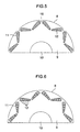
- Figs. 2A and 2B are diagrams for illustrating the configuration of the permanent magnet 12.
- the permanent-magnet thickness of the permanent magnet 12 is set such that an inequality T1 > T2 holds.
- T1 is the thickness of the permanent-magnet edge portion which is positioned on the outer-diameter side of the rotor iron-core 9 when the permanent magnets 12 are deployed into the V-character pattern
- T2 is the thickness of the permanent-magnet edge portion which is positioned on the inner-diameter side of the rotor iron-core 9.
- the location at which the eddy current is induced in a concentrated manner is the permanent-magnet edge portion which is positioned on the outer-diameter side of the rotor iron-core 9.
- This eddy current causes the permanent magnet to liberate heat, thereby resulting in the demagnetization of the permanent magnet.
- Thickening the thickness of the permanent-magnet edge portion on the outer-diameter side at which the eddy current is induced in a concentrated manner is outstandingly effective for preventing the demagnetization.
- Thickening the permanent-magnet thickness increases the Permeance coefficient, thereby making it possible to prevent the demagnetization due to the heat liberation.
- 2 pieces of curved-line portions are provided on the permanent-magnet edge portion on the outer-diameter side of the rotor iron-core 9, which becomes the edge portion of the V-character pattern of the permanent magnets 12.
- curvature radiuses of the curved-line portions are Ra1 and Rb1 respectively. Furthermore, 2 pieces of curved-line portions are also provided on the permanent-magnet edge portion on the inner-diameter side of the rotor iron-core 9, which becomes the center of the V-character pattern, Also, it is assumed that curvature radiuses of the curved-line portions are Ra2 and Rb2 respectively.
- 1 piece of curved-line portion is also provided on the permanent-magnet edge portion on the inner-diameter side of the rotor iron-core 9, which becomes the center of the V-character pattern.
- curvature radiuses of the curved-line portions are R1 and R2 respectively.
- T1 and T2 the condition for T1 and T2 is given as follows: The T1/T2 (T1 > T2) ratio is set, and then, a range of 1. 5 ⁇ T1/T2 ⁇ 3. 8 is determined and set as the optimum range for the T1/T2 ratio.
- T1/T2 T1 > T2
- a range of 1. 5 ⁇ T1/T2 ⁇ 3. 8 is determined and set as the optimum range for the T1/T2 ratio.
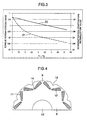
- Fig. 3 illustrates the relationship among the T1/T2 ratio, torque normalization value, and demagnetization-temperature normalization value.
- a line 20 denotes the torque normalization value, where the value at which the specification torque is satisfied is normalized into 1.
- a line 21 denotes the demagnetization-temperature normalization value, where the temperature at which the demagnetization occurs is normalized into 1.
- the target demagnetization temperature requires that the demagnetization-temperature normalization value be made smaller than 1. Accordingly, simultaneously satisfying both of the target torque and the target demagnetization temperature requires the following condition: Namely, from the drawing, the torque normalization value is satisfied when the T1/T2 ratio is lower than 3. 8, and simultaneously, the demagnetization-temperature normalization value is satisfied when the T1/T2 ratio is higher than 1. 5.
- This simultaneous condition makes it possible to operate the present embodiment as the permanent-magnet type electric rotating machine without any questions. On account of this, it is desirable to set the T1/T2 ratio into the range of 1. 5 ⁇ T1/T2 ⁇ 3. 8.
- Setting T1 and T2 in this way makes it possible to acquire the effects without increasing the usage amount of the permanent magnet, thereby allowing implementation of a suppression in the cost.
- Fig. 4 is a one-half edge-portion cross-sectional diagram of the rotor, which becomes a second embodiment of the present invention.
- a concave portion 16 is allowed to be provided in the outer circumference portion of the rotor iron-core 9, which becomes the center of the V-character pattern of the rotor 8, and which has been illustrated in the first embodiment.
- Providing the concave portion 16 makes it possible to reduce the weight of the iron-core which becomes the central portion of the V-character pattern, thereby allowing a reduction in the concentration stress concentrated onto the connection portion 14 which becomes the inner-diameter side of the rotor iron-core 9 of the V-character pattern's center.
- an air layer is created in the portion in which the concave portion 16 has been provided.
- This air layer allows implementation of a reduction in the temperature transmitted to the permanent magnet 12. Also, a similar effect can be obtained by providing an empty hole between the connection portion 14 on the inner-diameter side of the rotor iron-core 9 which becomes the center of the V-character pattern, and the outer circumference of the rotor iron-core 9 which becomes the center of the V-character pattern.
- Fig. 5 is a one-half edge-portion cross-sectional diagram of the rotor, which becomes a third embodiment of the present invention.
- the concave portion 16 is allowed to be provided in the inter-pole outer circumference in which polarities of the rotor 8 differ from each other, and which has been illustrated in the first and second embodiments. Providing the concave portion 16 creates an air layer. This air layer allows implementation of a reduction in the temperature transmitted to the permanent magnet 12.
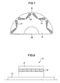
- Fig. 6 is a one-half edge-portion cross-sectional diagram of the rotor, which becomes a fourth embodiment of the present invention.
- Each of the permanent magnets 12, which are deployed into the V-character pattern in the rotor 8, and which have been illustrated in the first, second, and third embodiments, is allowed to be divided in such a manner as to become perpendicular to the inclination angle of the V-character pattern. Dividing the permanent magnet 12 makes it possible to reduce the eddy current.
- a connection portion 17 is allowed to be provided between the permanent magnets resulting from this division. Increasing the connection portion 17 heightens the rigidity of the rotor iron-core 9, thereby making it possible to reduce the stress due to the centrifugal force.
- Fig. 8 is an axis-direction cross-sectional diagram of the rotor, which becomes a fifth embodiment of the present invention.
- Each of the permanent magnets 12, which have been illustrated in the first, second, and third embodiments, is allowed to be divided in the axis direction. Dividing the permanent magnet 12 in the axis direction and embedding the magnets resulting from this division makes it possible to enhance the assembly property of the rotor 8.
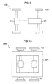
- Fig. 9 illustrates an embodiment where the electric rotating machine of the present invention is applied to an automobile.
- the automobile 100 includes the permanent-magnet type electric rotating machine 1 illustrated in the first to the fourth embodiments, an acceleration gear 101, and wheels 102.
- the permanent-magnet type electric rotating machine 1 drives the wheels 102 via the acceleration gear 101.
- a plurality of electric rotating machines can be installed to be used for the driving.
- Fig. 10 illustrates an embodiment where the electric rotating machine of the present invention is applied to a train.
- the train 200 includes the permanent-magnet type electric rotating machine 1 illustrated in the first to the fourth embodiments, an acceleration gear 101, and wheels 102.
- the permanent-magnet type electric rotating machine 1 drives the wheels 102 via the acceleration gear 101.
- two permanent-magnet type electric rotating machines 1 are illustrated in the drawing, one electric rotating machine, or a plurality of, i.e., two or more electric rotating machines can be installed to be used for the driving.
Landscapes
- Engineering & Computer Science (AREA)
- Power Engineering (AREA)
- Life Sciences & Earth Sciences (AREA)
- Sustainable Development (AREA)
- Sustainable Energy (AREA)
- Transportation (AREA)
- Mechanical Engineering (AREA)
- Permanent Field Magnets Of Synchronous Machinery (AREA)
- Iron Core Of Rotating Electric Machines (AREA)
Abstract
Description
- The present invention relates to a permanent-magnet type electric rotating machine, a permanent-magnet type electric rotating machine system and especially an automobile-or-train-targeted permanent-magnet type electric rotating machine system including the same machine.
- Up to the present time, an induction motor has been employed as the electric rotating machine used for railroad vehicles. In recent years, however, there has been a growing trend to employ a permanent-magnet type electric rotating machine which allows its small-sized and light-weighted implementation and high-efficiency implementation. This growing trend has arisen from low-cost implementation of the permanent magnet and prevalence of the high-performance inverter.
- Under the circumstances like this, in order to improve electric characteristics and strength characteristics of the electric rotating machine, consideration is now being given to the permanent-magnet type rotor structure of various forms. In
JP-A-9-90517 - In the case of the railroad-vehicle-targeted motor, its weight exerts a significant influence on the riding comfort feeling of the railroad vehicle. Accordingly, a weight reduction in the electric rotating machine becomes important. The light-weighted implementation of the electric rotating machine increases its output density. Nevertheless, the small-sized implementation in the constitution of the electric rotating machine increases an influence exerted by the magnetic saturation inside the rotating machine. As a result, a current passing through to the stator is increased in order to satisfy the specification output. The increase in the current also increases a magnet eddy current caused by the armature reaction. Moreover, the increase in the magnet eddy current causes the magnet to liberate heat, thereby giving rise to a problem of the demagnetization. This problem requires the execution of a demagnetization countermeasure against the heat liberation due to the magnet eddy current.
- In
JP-A-9-90517 - In the present invention, as the countermeasure against the heat liberation due to the magnet eddy current, the permanent-magnet type electric rotating machine is configured as follows: The deployment of permanent magnets is configured into V-character pattern, the permanent magnets constituting 1-pole inside the rotor iron-core of a rotor. The 1-pole constituting permanent magnets are deployed along a circumferential direction of the rotor iron-core with their polarity changed alternately. Connection portions are provided among the center of the V-character pattern, which becomes the inner-diameter side of the rotor iron-core, the outermost-diameter sides of the permanent magnets, which become right and left edge portions of the V-character pattern, and the outer circumference of the rotor iron-core. Then, the permanent magnets are embedded. The configuration of each permanent magnet is designed as follows: From the thickness of the permanent-magnet edge portion on the inner-diameter side of the rotor iron-core, which becomes the center of the V-character pattern, the thickness of the permanent magnet gradually increases toward the outer-diameter side of the rotor iron-core, which become the right and left edge portions of the V-character pattern. Simultaneously, curved lines are provided on both edge portions of the permanent magnet.
- It is an object of the invention to avoid the above mentioned disadvantages and to improve a permanent-magnet type electric rotating machine in order to prevent heat demagnetization.
- This object is solved by a permanent-magnet type electric rotating machine with the features of
clam 1. - According to the present invention, it becomes possible to prevent the heat demagnetization due to the eddy current, which is induced in a manner of being concentrated onto the edge portions of the permanent magnet on the outer-diameter side of the rotor iron-core.
- Further advantages and possible applications of the present invention become apparent from the following detailed description with reference to the amplifying embodiments illustrated by way of example in the drawings.
- In the description, the appended claims, the abstract and in the drawings, use is made of the terms and corresponding reference numerals summarized in the list of reference signs. In the drawings is shown:
- Fig. 1
- an explanatory diagram for explaining a carry-out method for the electric rotating machine (first embodiment);
- Figs. 2A and 2B
- explanatory diagrams for illustrating the configuration of the permanent magnet (first embodiment);
- Fig. 3
- an explanatory diagram for explaining the relationship among the permanent-magnet thickness, torque normalization value, and demagnetization-temperature normalization value (first embodiment);
- Fig. 4
- an explanatory diagram for explaining a carry-out method for the electric rotating machine (second embodiment);
- Fig. 5
- an explanatory diagram for explaining a carry-out method for the electric rotating machine (third embodiment);
- Fig. 6
- an explanatory diagram for explaining a carry-out method for the electric rotating machine (fourth embodiment);
- Fig. 7
- an explanatory diagram for explaining the carry-out method for the electric rotating machine (fourth embodiment);
- Fig. 8
- an explanatory diagram for explaining a carry-out method for the electric rotating machine (fifth embodiment);
- Fig. 9
- an explanatory diagram for explaining a carry-out method for the electric rotating machine (sixth embodiment), and
- Fig. 10
- an explanatory diagram for explaining a carry-out method for the electric rotating machine (seventh embodiment).
- Hereinafter, referring to the drawings, the explanation will be given below concerning details of the present invention. In each drawing, the same reference numerals are affixed to the same configuration components.
-
Fig. 1 is a cross-sectional diagram of the permanent-magnet type electric rotating machine, which becomes a first embodiment of the present invention. The permanent-magnet typeelectric rotating machine 1 is an 8-pole & 36-slot electric rotating machine. This 8-pole & 36-slot machine is used for a a-few-hundreds-of-kW-class train, and rotates in a range of 300 to 7000 min+. Astator 2 is a distribution-winding stator, which includes a cylindrical stator iron-core equipped with a plurality ofteeth 3 that protrude from a yoke portion onto its inner-circumference surface, and which also includes acoil 4 formed by winding an elemental wire in a distribution-like manner using theteeth 3. Thecoil 4 is configured by winding a 3-phase (i.e., U-phase, V-phase, and W-phase) winding so that the 8 poles are electrically implemented with the 36 slots. Anupper coil 6 is deployed on the outer-diameter side of eachslot 5 formed between theteeth 3, and alower coil 7 is deployed on the inner-diameter side of eachslot 5. Thecoil 4 is wound in accordance with a scheme referred to as "short-pitch winding", which allows implementation of a reduction in the eddy current loss in comparison with the full-pitch winding. Thecoil 4 is wire-connected such that, of the numbers ranging from #1 to #36 and affixed to theslots 5 for convenience in a counterclockwise direction, the elemental wire, which has left thelower coil 7 of the #1 slot, enters theupper coil 6 of the #5 slot. This wire-connection constitutes the above-described 3-phase winding which is repeated in the circumferential direction. The number of the #5 slot is the value of 5. This value results from rounding off 4. 5 which is obtained by dividing theslot number 36 by thepole number 8. Setting the ratio between the winding pitch and the magnetic-pole pitch (i.e., short-pitch degree) at 5/6 makes it possible to reduce the fifth and seventh space harmonics. Incidentally, in the present embodiment, the combination of the 8 poles and the 36 slots has been employed. It is also allowable, however, to employ a combination of some other pole number and slot number, and further, the combination with the concentration winding or the full-pitch winding. - A
rotor 8 is deployed such that therotor 8 becomes coaxially rotatable with thestator 2. Ashaft 10 is fixed onto the axis of a rotor iron-core 9. 1-poleconstituting magnet slots 11 are deployed into V-character pattern along an outer circumference portion of the rotor iron-core 9.Permanent magnets 12 are embedded into the 1-poleconstituting magnet slots 11, For 1 pole, the 2 pieces of same-polaritypermanent magnets 12 are embedded into the V-character pattern, i,e., the 16 pieces ofpermanent magnets 12 are embedded in total. The configuration of each embeddedpermanent magnet 12 is designed as follows: From the thickness of the permanent-magnet edge portion on the inner-diameter side of the rotor iron-core 9, which becomes the center of the V-character pattern, the thickness of the permanent magnet gradually increases toward the outer-diameter side of the rotor iron-core 9, which become the right and left edge portions of the V-character pattern. Simultaneously, curved-line portions 13 are provided on both edge portions of the permanent magnet. Also, aconnection portion 14 is provided on the inner-diameter side of the rotor iron-core 9, which becomes the center of the V-character pattern. Moreover, aconnection portion 15 is provided between the outermost-diameter sides of the permanent magnets inside the rotor iron-core, which become the right and left edge portions of the V-character pattern, and the outer circumference of the rotor iron-core 9. Providing theconnection portions core 9, thereby making it possible to reduce the stress due to the centrifugal force. When a flat-plate permanent magnet is used, a curved-line portion is provided on the magnet slot in order to reduce the concentration stress. Providing the curved-line portion, however, requires the cross-sectional area of the magnet slot which is wider than the cross-sectional area of the flat-plate permanent magnet. Then, just like the present embodiment, by forming the configuration of themagnet slot 11 into a configuration which is geometrically similar to the configuration of thepermanent magnet 12, it becomes possible to reduce a clearance between thepermanent magnet 12 and themagnet slot 11. This reduction increases an effective magnetic flux supplied from thepermanent magnet 12. Also, it becomes possible to limit a movement of thepermanent magnet 12 due to the centrifugal force. Also, in order to prevent the phenomena such as rust, flaw, and chipping of the permanent magnet, a surface processing such as coating or plating is applied to the surface of the permanent magnet. At this time, the edge portions of the permanent magnet include acute-angle portions when the flat-plate permanent magnet is used. As a result, a significant dimension error occurs due to phenomena such as slack, accumulation, and a variation in the surface thickness. On account of this significant dimension error, the magnet-slot dimension of the rotor iron-core becomes larger. This largeness increases the clearance portion between the permanent magnet and the magnet slot, thereby worsening the magnetic characteristics. Then, just like the present embodiment, providing the curved-line portions on the edge portions of the magnet results in implementation of the following effects: It becomes easier to acquire a uniform surface-processed thickness, thereby being capable of reducing the dimension error of the permanent magnet. Also, it also becomes possible to reduce the clearance portion between the permanent magnet and the magnet slot, thereby being capable of preventing the worsening in the magnetic characteristics. -
Figs. 2A and 2B are diagrams for illustrating the configuration of thepermanent magnet 12. The permanent-magnet thickness of thepermanent magnet 12 is set such that an inequality T1 > T2 holds. Here, it is assumed that T1 is the thickness of the permanent-magnet edge portion which is positioned on the outer-diameter side of the rotor iron-core 9 when thepermanent magnets 12 are deployed into the V-character pattern, and that T2 is the thickness of the permanent-magnet edge portion which is positioned on the inner-diameter side of the rotor iron-core 9. The location at which the eddy current is induced in a concentrated manner is the permanent-magnet edge portion which is positioned on the outer-diameter side of the rotor iron-core 9. This eddy current causes the permanent magnet to liberate heat, thereby resulting in the demagnetization of the permanent magnet. Thickening the thickness of the permanent-magnet edge portion on the outer-diameter side at which the eddy current is induced in a concentrated manner is outstandingly effective for preventing the demagnetization. Thickening the permanent-magnet thickness increases the Permeance coefficient, thereby making it possible to prevent the demagnetization due to the heat liberation. Moreover, 2 pieces of curved-line portions are provided on the permanent-magnet edge portion on the outer-diameter side of the rotor iron-core 9, which becomes the edge portion of the V-character pattern of thepermanent magnets 12. Also, it is assumed that curvature radiuses of the curved-line portions are Ra1 and Rb1 respectively. Furthermore, 2 pieces of curved-line portions are also provided on the permanent-magnet edge portion on the inner-diameter side of the rotor iron-core 9, which becomes the center of the V-character pattern, Also, it is assumed that curvature radiuses of the curved-line portions are Ra2 and Rb2 respectively. At this time, by setting Ra1 into a range of 0 < Ra1 ≦ T1, Rb1 into a range of 0 < Rb1 ≦ T1, Ra2 into a range of 0 < Ra2 ≦ T2, and Rb2 into a range of 0 < Rb2 ≦ T2, it becomes possible to relax the concentration stress generated by the centrifugal force - shown inFig.2A . In addition, as shown inFig.2B ,1 piece of curved-line portion is provided on the permanent-magnet edge portion on the outer-diameter side of the rotor iron-core 9, which becomes the edge portion of the V-character pattern of thepermanent magnets 12. Also, 1 piece of curved-line portion is also provided on the permanent-magnet edge portion on the inner-diameter side of the rotor iron-core 9, which becomes the center of the V-character pattern. Also, it is assumed that curvature radiuses of the curved-line portions are R1 and R2 respectively. At this time, by setting R1 into a range of 0 < R1 ≦ T1, and R2 into a range of 0 < R2 ≦ T2, it also becomes possible to expect a similar effect. Incidentally, in the present drawing, it turns out that Ra1 > Rb1, and Ra2 > Rb2 are set. Another combination, however, is also allowable as long as Ra1, Rb1, Ra2, and Rb2 fall within the above-described ranges. - In the present embodiment, the condition for T1 and T2 is given as follows: The T1/T2 (T1 > T2) ratio is set, and then, a range of 1. 5 < T1/T2 < 3. 8 is determined and set as the optimum range for the T1/T2 ratio. Hereinafter, referring to
Fig. 3 , the explanation will be given below concerning this relationship. -
Fig. 3 illustrates the relationship among the T1/T2 ratio, torque normalization value, and demagnetization-temperature normalization value. On the horizontal axis, there is a tendency that, when the value of T1 is increased, the torque is lowered although the upper-limit of the demagnetization temperature is heightened. Aline 20 denotes the torque normalization value, where the value at which the specification torque is satisfied is normalized into 1. Also, aline 21 denotes the demagnetization-temperature normalization value, where the temperature at which the demagnetization occurs is normalized into 1. When attention is focused on the torque normalization value, satisfying the target torque requires that the torque normalization value be made larger than 1. Meanwhile, when attention is focused on the demagnetization temperature, satisfying the target demagnetization temperature requires that the demagnetization-temperature normalization value be made smaller than 1. Accordingly, simultaneously satisfying both of the target torque and the target demagnetization temperature requires the following condition: Namely, from the drawing, the torque normalization value is satisfied when the T1/T2 ratio is lower than 3. 8, and simultaneously, the demagnetization-temperature normalization value is satisfied when the T1/T2 ratio is higher than 1. 5. This simultaneous condition makes it possible to operate the present embodiment as the permanent-magnet type electric rotating machine without any questions. On account of this, it is desirable to set the T1/T2 ratio into the range of 1. 5 < T1/T2 < 3. 8. Incidentally, when setting T1 and T2, it is desirable to set T1 and T2 such that the resultant area will become equal to the cross-sectional area of the flat-plate permanent magnet at the time when the flat-plate magnet is employed as the criterion - i.e., T1 = T2. Setting T1 and T2 in this way makes it possible to acquire the effects without increasing the usage amount of the permanent magnet, thereby allowing implementation of a suppression in the cost. -
Fig. 4 is a one-half edge-portion cross-sectional diagram of the rotor, which becomes a second embodiment of the present invention. Aconcave portion 16 is allowed to be provided in the outer circumference portion of the rotor iron-core 9, which becomes the center of the V-character pattern of therotor 8, and which has been illustrated in the first embodiment. Providing theconcave portion 16 makes it possible to reduce the weight of the iron-core which becomes the central portion of the V-character pattern, thereby allowing a reduction in the concentration stress concentrated onto theconnection portion 14 which becomes the inner-diameter side of the rotor iron-core 9 of the V-character pattern's center. Moreover, an air layer is created in the portion in which theconcave portion 16 has been provided. This air layer allows implementation of a reduction in the temperature transmitted to thepermanent magnet 12. Also, a similar effect can be obtained by providing an empty hole between theconnection portion 14 on the inner-diameter side of the rotor iron-core 9 which becomes the center of the V-character pattern, and the outer circumference of the rotor iron-core 9 which becomes the center of the V-character pattern. -
Fig. 5 is a one-half edge-portion cross-sectional diagram of the rotor, which becomes a third embodiment of the present invention. Theconcave portion 16 is allowed to be provided in the inter-pole outer circumference in which polarities of therotor 8 differ from each other, and which has been illustrated in the first and second embodiments. Providing theconcave portion 16 creates an air layer. This air layer allows implementation of a reduction in the temperature transmitted to thepermanent magnet 12. -
Fig. 6 is a one-half edge-portion cross-sectional diagram of the rotor, which becomes a fourth embodiment of the present invention. Each of thepermanent magnets 12, which are deployed into the V-character pattern in therotor 8, and which have been illustrated in the first, second, and third embodiments, is allowed to be divided in such a manner as to become perpendicular to the inclination angle of the V-character pattern. Dividing thepermanent magnet 12 makes it possible to reduce the eddy current. Furthermore, as illustrated inFig. 7 , aconnection portion 17 is allowed to be provided between the permanent magnets resulting from this division. Increasing theconnection portion 17 heightens the rigidity of the rotor iron-core 9, thereby making it possible to reduce the stress due to the centrifugal force. -
Fig. 8 is an axis-direction cross-sectional diagram of the rotor, which becomes a fifth embodiment of the present invention. Each of thepermanent magnets 12, which have been illustrated in the first, second, and third embodiments, is allowed to be divided in the axis direction. Dividing thepermanent magnet 12 in the axis direction and embedding the magnets resulting from this division makes it possible to enhance the assembly property of therotor 8. -
Fig. 9 illustrates an embodiment where the electric rotating machine of the present invention is applied to an automobile. Theautomobile 100 includes the permanent-magnet type electricrotating machine 1 illustrated in the first to the fourth embodiments, anacceleration gear 101, andwheels 102. The permanent-magnet type electricrotating machine 1 drives thewheels 102 via theacceleration gear 101. Also, although only one permanent-magnet type electricrotating machine 1 is illustrated in the drawing, a plurality of electric rotating machines can be installed to be used for the driving. -
Fig. 10 illustrates an embodiment where the electric rotating machine of the present invention is applied to a train. Thetrain 200 includes the permanent-magnet type electricrotating machine 1 illustrated in the first to the fourth embodiments, anacceleration gear 101, andwheels 102. The permanent-magnet type electricrotating machine 1 drives thewheels 102 via theacceleration gear 101. Also, although two permanent-magnet type electricrotating machines 1 are illustrated in the drawing, one electric rotating machine, or a plurality of, i.e., two or more electric rotating machines can be installed to be used for the driving. - It should be further understood by those skilled in the art that although the foregoing description has been made on embodiments of the invention, the invention is not limited thereto and various changes and modifications may be made without departing from the spirit of the invention and the scope of the appended claims.
-
- 1
- rotating machine
- 2
- stator
- 3
- teeth
- 4
- coil
- 5
- slot
- 6
- upper coil
- 7
- lower coil
- 8
- rotor
- 9
- iron core
- 10
- shaft
- 11
- magnet slots
- 12
- permanent magnets
- 13
- curved line portions
- 14
- connection portion
- 15
- connection portion
- 16
- concave portion
- 17
- connection portion
- 100
- automobile
- 101
- acceleration gear
- 102
- wheels
- 200
- train
Claims (13)
- A permanent-magnet type electric rotating machine (1) comprising a stator (2) and a rotor (8), characterized in that permanent magnets (12) are provided in a rotor iron-core (9) of said permanent-magnet rotor (8), one pole being configured by deploying said permanent magnets (12) into V-character pattern, said one pole being deployed along a circumferential direction with its polarity changed alternately; thickness of each of said permanent magnets (12) are gradually increasing from central portion of said V-character pattern toward right and left edge portions of said V-character pattern; and a curved line is provided on said edge portions of said V-character pattern.
- The permanent-magnet type electric rotating machine according to claim 1, characterized in that each of said permanent magnets (12) is divided in such a manner as to become perpendicular to inclination angle of said V-character pattern.
- A permanent-magnet type electric rotating machine (1) comprising a stator (2) and a rotor (8), characterized in that permanent magnets (12) are provided in a rotor iron-core (9) of said permanent-magnet rotor (8), one pole being configured by deploying said permanent magnets (12) into V-character pattern, said one pole being deployed along a circumferential direction with its polarity changed alternately; a connection portion (14) is provided between said permanent magnets (12) which are deployed on inner-diameter side of said rotor iron-core (9), and which constitute central portion of said V-character pattern; a connection portion (15) is provided between said permanent magnet (12) and outer circumference of said rotor iron-core (9), said permanent magnet (12) being deployed on outer-diameter side of said rotor iron-core (9), and constituting an edge portion of said V-character pattern; said connection portions (14, 15) are used for establishing connection between said outer-diameter side of said rotor iron-core (9) and said inner-diameter side thereof; and a relationship T1 > T2 being specified between T1 and T2, wherein T1 is thickness of said permanent magnet (12) which is positioned on said outer-diameter side of said rotor iron-core (9), and which becomes said edge portion of said V-character pattern, and T2 is thickness of said permanent magnet (12) which is positioned on said inner-diameter side of said rotor iron-core (9), and which becomes said central portion of said V-character pattern.
- The permanent-magnet type electric rotating machine according to claim 3, characterized in that a curved-line portion (13) is provided on said edge portion of said permanent magnet (12) which is positioned on said outer-diameter side of said rotor (8), and which becomes said edge portion of said V-character pattern; a curved-line portion (13) being also provided on said edge portion of said permanent magnet (12) which is positioned on said inner-diameter side of said rotor (8), and which becomes said central portion of said V-character pattern; and when determining that curvature radiuses of said curved-line portions (13) are R1 and R2 respectively, relationships 0 < R1 < T1 and 0 < R2 < T2 are specified between said R1 and said T1, and between said R2 and said T2.
- The permanent-magnet type electric rotating machine according to claim 3 or 4, characterized in that configuration of a permanent-magnet insertion aperture of said rotor iron-core (9) is formed into a configuration which is geometrically similar to configuration of said permanent magnet (12).
- The permanent-magnet type electric rotating machine according to anyone of the claims 3 to 5, characterized in that said stator (2) comprises a plurality of teeth (3) which protrude onto inner-circumference surface of a yoke portion, a coil being wound around said teeth (3) in accordance with concentration winding or distribution winding.
- The permanent-magnet type electric rotating machine according to anyone of the claims 3 to 6, characterized in that concave portion (16) is provided in said outer circumference portion of said rotor iron-core (9) in said central portion of said V-character pattern.
- The permanent-magnet type electric rotating machine according to anyone of the claims 3 to 7, characterized in that a concave portion (16) is provided in said outer circumference portion of said rotor iron-core (9) between poles of said rotor (8) whose polarities differ from each other.
- The permanent-magnet type electric rotating machine according to anyone of the claims 3 to 8, characterized in that each of said permanent magnets (12) is divided in such a manner as to become perpendicular to inclination angle of said V-character pattern.
- The permanent-magnet type electric rotating machine according to anyone of the claims 3 to 9, characterized in that an empty hole is provided between said connection portion (14) and said outer circumference of said rotor iron-core (9) in said center of said V-character pattern, said connection portion (14) being positioned on said inner-diameter side of said rotor iron-core (9), and becoming said center of said V-character pattern of said rotor (8).
- The permanent-magnet type electric rotating machine according to anyone of the claims 3 to 10, characterized in that each of said permanent magnets (12) is divided in its axis direction.
- A permanent-magnet type electric rotating machine system for automobile, characterized in that said permanent-magnet type electric rotating machine (1) described in anyone of the claims 3 to 11 is employed as its power source.
- The permanent-magnet type electric rotating machine system for train, characterized in that said permanent-magnet type electric rotating machine (1) described in anyone of the claims 3 to 11 is employed as its power source.
Applications Claiming Priority (1)
| Application Number | Priority Date | Filing Date | Title |
|---|---|---|---|
| JP2008168045A JP4627788B2 (en) | 2008-06-27 | 2008-06-27 | Permanent magnet rotating electric machine |
Publications (2)
| Publication Number | Publication Date |
|---|---|
| EP2139093A2 true EP2139093A2 (en) | 2009-12-30 |
| EP2139093A3 EP2139093A3 (en) | 2011-07-13 |
Family
ID=41172080
Family Applications (1)
| Application Number | Title | Priority Date | Filing Date |
|---|---|---|---|
| EP09163623A Ceased EP2139093A3 (en) | 2008-06-27 | 2009-06-24 | Permanent-magnet type electric rotating machine |
Country Status (3)
| Country | Link |
|---|---|
| US (1) | US7952249B2 (en) |
| EP (1) | EP2139093A3 (en) |
| JP (1) | JP4627788B2 (en) |
Cited By (7)
| Publication number | Priority date | Publication date | Assignee | Title |
|---|---|---|---|---|
| EP2362525A3 (en) * | 2010-02-26 | 2011-12-28 | General Electric Company | Rotor structure for interior permanent magnet electromotive machine |
| CN103219814A (en) * | 2013-04-09 | 2013-07-24 | 沈阳工业大学 | Asynchronous starting permanent magnet synchronous motor rotor based on permanent magnets with different residual magnetic densities |
| WO2015074023A1 (en) | 2013-11-18 | 2015-05-21 | Steering Solutions Ip Holding Corporation | Low cost permanent magnet motor for an electric power steering system |
| EP2863517A4 (en) * | 2012-06-14 | 2016-04-20 | Daikin Ind Ltd | INTEGRATED MAGNET TYPE ROTARY ELECTRIC MACHINE |
| CN105990920A (en) * | 2015-02-12 | 2016-10-05 | 珠海格力节能环保制冷技术研究中心有限公司 | Rotor iron core and motor having the same |
| EP3154157A1 (en) * | 2015-10-08 | 2017-04-12 | Samsung Electronics Co., Ltd. | Bldc motor |
| US9979243B2 (en) | 2014-11-18 | 2018-05-22 | Steering Solutions Ip Holding Corporation | Low cost injection molded buried permanent magnet motor for an electric power steering system |
Families Citing this family (37)
| Publication number | Priority date | Publication date | Assignee | Title |
|---|---|---|---|---|
| JP5589345B2 (en) * | 2009-10-21 | 2014-09-17 | 富士電機株式会社 | Permanent magnet rotating electric machine |
| JP5292271B2 (en) * | 2009-12-24 | 2013-09-18 | 株式会社日立製作所 | Permanent magnet rotating electric machine |
| JP5099147B2 (en) * | 2010-01-18 | 2012-12-12 | トヨタ自動車株式会社 | Rotor for IPM motor and manufacturing method thereof |
| JP5479978B2 (en) * | 2010-03-30 | 2014-04-23 | アイシン・エィ・ダブリュ株式会社 | Rotating electric machine |
| JP5482544B2 (en) * | 2010-07-28 | 2014-05-07 | トヨタ自動車株式会社 | Rotating electric machine |
| JP5331761B2 (en) * | 2010-08-09 | 2013-10-30 | 株式会社日立製作所 | Permanent magnet rotating electric machine |
| JP5261836B2 (en) | 2010-11-01 | 2013-08-14 | 本田技研工業株式会社 | Rotating electrical machine rotor |
| JP2012139068A (en) * | 2010-12-27 | 2012-07-19 | Mitsubishi Electric Corp | Rotor for embedded magnet type motor |
| JP2012157150A (en) * | 2011-01-26 | 2012-08-16 | Hitachi Ltd | Permanent magnet type rotary electric machine |
| JP5310790B2 (en) * | 2011-06-10 | 2013-10-09 | 株式会社デンソー | Rotating electrical machine rotor |
| JP5895429B2 (en) * | 2011-10-03 | 2016-03-30 | 富士電機株式会社 | Embedded magnet type rotating electrical machine |
| WO2013077115A1 (en) * | 2011-11-21 | 2013-05-30 | 本田技研工業株式会社 | Rotating electric machine |
| US20140265704A1 (en) * | 2011-12-05 | 2014-09-18 | Korea Electronics Technology Institute | Rotor including permanent magnets having different thicknesses and motor including same |
| CN103166345B (en) * | 2011-12-12 | 2017-12-08 | 德昌电机(深圳)有限公司 | Brushless electric machine and its rotor |
| JP5879116B2 (en) * | 2011-12-15 | 2016-03-08 | 株式会社日立製作所 | Rotating electric machine, railway vehicle including the same, and electric vehicle |
| JP6007593B2 (en) * | 2012-05-25 | 2016-10-12 | 株式会社ジェイテクト | Rotor, rotating electric machine provided with the same, and method of manufacturing rotor |
| JP5929561B2 (en) * | 2012-06-29 | 2016-06-08 | 株式会社ジェイテクト | Electric rotating machine and manufacturing method thereof |
| WO2014045445A1 (en) * | 2012-09-24 | 2014-03-27 | 三菱電機株式会社 | Permanent magnet-embedded electric motor |
| ITMI20131531A1 (en) * | 2013-09-17 | 2015-03-18 | Brembo Sgl Carbon Ceramic Brakes S P A | DISC FOR DISC BRAKES AND BRAKING SYSTEM EQUIPPED WITH THIS DISC |
| JP6294720B2 (en) * | 2014-03-24 | 2018-03-14 | アイチエレック株式会社 | Permanent magnet motor |
| JP6279947B2 (en) * | 2014-03-24 | 2018-02-14 | アイチエレック株式会社 | Permanent magnet motor |
| WO2016035191A1 (en) * | 2014-09-04 | 2016-03-10 | 株式会社安川電機 | Rotating electric machine and method for manufacturing rotor core |
| US10236742B2 (en) | 2014-11-25 | 2019-03-19 | Black & Decker Inc. | Brushless motor for a power tool |
| US10418929B2 (en) | 2015-02-02 | 2019-09-17 | Mitsubishi Electric Corporation | Synchronous machine control device and permanent magnet temperature estimation method for synchronous machine |
| US10500708B2 (en) * | 2015-10-14 | 2019-12-10 | Black & Decker Inc. | Power tool |
| CN105958767A (en) * | 2016-05-11 | 2016-09-21 | 山东理工大学 | Built-in radial rare earth permanent magnet steel drive motor for electric automobiles |
| CN105978252A (en) * | 2016-05-11 | 2016-09-28 | 山东理工大学 | Production method for driving motor rotor internally provided with radial magnetic-field rare-earth permanent magnet steel |
| CN106451852A (en) * | 2016-10-26 | 2017-02-22 | 珠海格力节能环保制冷技术研究中心有限公司 | Rotor and permanent magnet motor |
| JP2018125918A (en) * | 2017-01-30 | 2018-08-09 | シナノケンシ株式会社 | Outer rotor motor |
| FR3067880B1 (en) * | 2017-06-15 | 2020-07-17 | Moteurs Leroy-Somer | ROTATING ELECTRIC MACHINE |
| TWM576750U (en) | 2017-07-25 | 2019-04-11 | 美商米沃奇電子工具公司 | Electrical composition, electric device system, battery pack, electric motor, motor assembly and electric motor assembly |
| JP7243117B2 (en) * | 2017-10-31 | 2023-03-22 | Tdk株式会社 | permanent magnets and motors |
| CN108462263B (en) * | 2018-03-29 | 2024-04-30 | 广东美芝制冷设备有限公司 | Motor, compressor and refrigeration equipment |
| JP7248837B2 (en) * | 2018-04-25 | 2023-03-29 | 株式会社日立インダストリアルプロダクツ | Rotating electric machine, rotating electric motor drive system, and electric vehicle |
| CN216398138U (en) | 2019-02-18 | 2022-04-29 | 米沃奇电动工具公司 | impact tool |
| JP7378369B2 (en) * | 2020-09-09 | 2023-11-13 | 日立Astemo株式会社 | Rotor of rotating electric machine, rotating electric machine and electric drive device |
| JP7478104B2 (en) * | 2021-01-08 | 2024-05-02 | 株式会社アイシン | Rotor core |
Citations (6)
| Publication number | Priority date | Publication date | Assignee | Title |
|---|---|---|---|---|
| JPH0990517A (en) | 1995-09-26 | 1997-04-04 | Canon Inc | Reciprocating drive device and image forming apparatus |
| EP1014542A2 (en) | 1998-12-25 | 2000-06-28 | Matsushita Electric Industrial Co., Ltd. | Motor having a rotor with interior split-permanent-magnet |
| DE19915664A1 (en) | 1999-04-07 | 2000-10-19 | Siemens Ag | Electrical machine with a stator |
| JP2004104962A (en) * | 2002-09-12 | 2004-04-02 | Toshiba Industrial Products Manufacturing Corp | Permanent magnet type reluctance type rotating electric machine |
| JP2006280195A (en) | 2005-03-01 | 2006-10-12 | Toshiba Corp | Permanent magnet rotating electric machine |
| US20070096578A1 (en) | 2005-10-31 | 2007-05-03 | Jahns Thomas M | Device having permanent-magnet pieces |
Family Cites Families (9)
| Publication number | Priority date | Publication date | Assignee | Title |
|---|---|---|---|---|
| US6049153A (en) * | 1996-02-23 | 2000-04-11 | Matsushita Electric Industrial Co., Ltd. | Motor |
| JP2000245085A (en) * | 1998-12-25 | 2000-09-08 | Matsushita Electric Ind Co Ltd | motor |
| JP2002153000A (en) * | 2000-11-10 | 2002-05-24 | Sankyo Seiki Mfg Co Ltd | Permanent magnet embedded motor and method of manufacturing the same |
| JP2002300742A (en) * | 2001-03-29 | 2002-10-11 | Mitsubishi Heavy Ind Ltd | Embedded magnet motor, and magnetic flux reinforcement method for embedded magnet motor |
| JP3801477B2 (en) * | 2001-10-11 | 2006-07-26 | 三菱電機株式会社 | Synchronous induction motor rotor, synchronous induction motor, fan motor, compressor, air conditioner, and refrigerator |
| JP2007097387A (en) * | 2005-08-31 | 2007-04-12 | Toshiba Corp | Rotating electric machine |
| US7436095B2 (en) * | 2005-10-31 | 2008-10-14 | Caterpillar Inc. | Rotary electric machine |
| JP5157138B2 (en) * | 2006-11-24 | 2013-03-06 | 株式会社日立製作所 | Permanent magnet rotating electrical machine and wind power generation system |
| JP4886624B2 (en) * | 2007-07-11 | 2012-02-29 | 株式会社日立製作所 | Permanent magnet type rotating electrical machine and permanent magnet type rotating electrical machine system |
-
2008
- 2008-06-27 JP JP2008168045A patent/JP4627788B2/en not_active Expired - Fee Related
-
2009
- 2009-06-22 US US12/488,923 patent/US7952249B2/en not_active Expired - Fee Related
- 2009-06-24 EP EP09163623A patent/EP2139093A3/en not_active Ceased
Patent Citations (6)
| Publication number | Priority date | Publication date | Assignee | Title |
|---|---|---|---|---|
| JPH0990517A (en) | 1995-09-26 | 1997-04-04 | Canon Inc | Reciprocating drive device and image forming apparatus |
| EP1014542A2 (en) | 1998-12-25 | 2000-06-28 | Matsushita Electric Industrial Co., Ltd. | Motor having a rotor with interior split-permanent-magnet |
| DE19915664A1 (en) | 1999-04-07 | 2000-10-19 | Siemens Ag | Electrical machine with a stator |
| JP2004104962A (en) * | 2002-09-12 | 2004-04-02 | Toshiba Industrial Products Manufacturing Corp | Permanent magnet type reluctance type rotating electric machine |
| JP2006280195A (en) | 2005-03-01 | 2006-10-12 | Toshiba Corp | Permanent magnet rotating electric machine |
| US20070096578A1 (en) | 2005-10-31 | 2007-05-03 | Jahns Thomas M | Device having permanent-magnet pieces |
Cited By (14)
| Publication number | Priority date | Publication date | Assignee | Title |
|---|---|---|---|---|
| US8541919B2 (en) | 2010-02-26 | 2013-09-24 | General Electric Company | Rotor structure for interior permanent magnet electromotive machine including laminations profiled along a segment of a bridge to define a concave and curved bridge profile |
| EP2362525A3 (en) * | 2010-02-26 | 2011-12-28 | General Electric Company | Rotor structure for interior permanent magnet electromotive machine |
| EP2863517A4 (en) * | 2012-06-14 | 2016-04-20 | Daikin Ind Ltd | INTEGRATED MAGNET TYPE ROTARY ELECTRIC MACHINE |
| CN103219814A (en) * | 2013-04-09 | 2013-07-24 | 沈阳工业大学 | Asynchronous starting permanent magnet synchronous motor rotor based on permanent magnets with different residual magnetic densities |
| CN103219814B (en) * | 2013-04-09 | 2015-04-08 | 沈阳工业大学 | Asynchronous starting permanent magnet synchronous motor rotor based on permanent magnets with different residual magnetic densities |
| CN105723594A (en) * | 2013-11-18 | 2016-06-29 | 操纵技术Ip控股公司 | Low-Cost Permanent Magnet Motors for Electric Power Steering |
| WO2015074023A1 (en) | 2013-11-18 | 2015-05-21 | Steering Solutions Ip Holding Corporation | Low cost permanent magnet motor for an electric power steering system |
| EP3055921A4 (en) * | 2013-11-18 | 2017-05-24 | Steering Solutions IP Holding Corporation | Low cost permanent magnet motor for an electric power steering system |
| US10205359B2 (en) | 2013-11-18 | 2019-02-12 | Steering Solutions Ip Holding Corporation | Low cost permanent magnet motor for an electric power steering system |
| US9979243B2 (en) | 2014-11-18 | 2018-05-22 | Steering Solutions Ip Holding Corporation | Low cost injection molded buried permanent magnet motor for an electric power steering system |
| CN105990920A (en) * | 2015-02-12 | 2016-10-05 | 珠海格力节能环保制冷技术研究中心有限公司 | Rotor iron core and motor having the same |
| EP3154157A1 (en) * | 2015-10-08 | 2017-04-12 | Samsung Electronics Co., Ltd. | Bldc motor |
| KR20170042072A (en) * | 2015-10-08 | 2017-04-18 | 삼성전자주식회사 | Interior permanent magnet type bldc motor |
| US10404116B2 (en) | 2015-10-08 | 2019-09-03 | Samsung Electronics Co., Ltd. | BLDC motor |
Also Published As
| Publication number | Publication date |
|---|---|
| JP2010011640A (en) | 2010-01-14 |
| US20090322175A1 (en) | 2009-12-31 |
| US7952249B2 (en) | 2011-05-31 |
| JP4627788B2 (en) | 2011-02-09 |
| EP2139093A3 (en) | 2011-07-13 |
Similar Documents
| Publication | Publication Date | Title |
|---|---|---|
| US7952249B2 (en) | Permanent-magnet type electric rotating machine and permanent-magnet type electric rotating machine system for automobile or train | |
| JP4886624B2 (en) | Permanent magnet type rotating electrical machine and permanent magnet type rotating electrical machine system | |
| US9190877B2 (en) | Rotor for rotating electric machine | |
| US8841807B2 (en) | Rotary electric machine with improved magnetic resistance | |
| US8884491B2 (en) | Multi-gap electric rotating machine with one-piece stator core | |
| CN112953054B (en) | Motor with noise reduction rotor notch | |
| US8217544B2 (en) | Motor-generator having stator and inner and outer rotors | |
| US20090315424A1 (en) | Permanent magnet synchronous machine with shell magnets | |
| US20130119810A1 (en) | Electric rotating machine | |
| JP3523557B2 (en) | Permanent magnet type rotating electric machine and hybrid electric vehicle using the same | |
| US8653714B2 (en) | Stator for electric rotating machine | |
| US9385567B2 (en) | Rotating electric machine | |
| CN103959608B (en) | Rotor and the electric rotating machine including the type rotor for electric rotating machine | |
| US8505674B2 (en) | Steering drive for a motor vehicle | |
| CN103683593A (en) | Rotor of motor, synchronous motor having the same and wound rotor synchronous motor | |
| JP2010161883A (en) | Permanent magnet type rotary electric machine | |
| CN103095088A (en) | Electric rotating machine | |
| US20150015110A1 (en) | Electric Rotating Machine | |
| JP5567775B2 (en) | Rotor and rotating electric machine | |
| JPWO2011155327A1 (en) | Concentrated winding stator of electric motor and method for manufacturing the same | |
| EP2047582A2 (en) | Axial-flux electric machine | |
| CN116472658B (en) | Rotating motor and electric power steering device | |
| JP7507840B2 (en) | Rotating electric machine, rotating electric motor drive system, and electric vehicle | |
| JP2020167893A (en) | Rotating electric machine and manufacturing method of rotating electric machine | |
| KR20160051580A (en) | Permanent magnet motor |
Legal Events
| Date | Code | Title | Description |
|---|---|---|---|
| PUAI | Public reference made under article 153(3) epc to a published international application that has entered the european phase |
Free format text: ORIGINAL CODE: 0009012 |
|
| 17P | Request for examination filed |
Effective date: 20090714 |
|
| AK | Designated contracting states |
Kind code of ref document: A2 Designated state(s): AT BE BG CH CY CZ DE DK EE ES FI FR GB GR HR HU IE IS IT LI LT LU LV MC MK MT NL NO PL PT RO SE SI SK TR |
|
| PUAL | Search report despatched |
Free format text: ORIGINAL CODE: 0009013 |
|
| AK | Designated contracting states |
Kind code of ref document: A3 Designated state(s): AT BE BG CH CY CZ DE DK EE ES FI FR GB GR HR HU IE IS IT LI LT LU LV MC MK MT NL NO PL PT RO SE SI SK TR |
|
| 17Q | First examination report despatched |
Effective date: 20131107 |
|
| STAA | Information on the status of an ep patent application or granted ep patent |
Free format text: STATUS: THE APPLICATION HAS BEEN REFUSED |
|
| 18R | Application refused |
Effective date: 20160813 |