JP5879116B2 - Rotating electric machine, railway vehicle including the same, and electric vehicle - Google Patents
Rotating electric machine, railway vehicle including the same, and electric vehicle Download PDFInfo
- Publication number
- JP5879116B2 JP5879116B2 JP2011274046A JP2011274046A JP5879116B2 JP 5879116 B2 JP5879116 B2 JP 5879116B2 JP 2011274046 A JP2011274046 A JP 2011274046A JP 2011274046 A JP2011274046 A JP 2011274046A JP 5879116 B2 JP5879116 B2 JP 5879116B2
- Authority
- JP
- Japan
- Prior art keywords
- rotor
- fan
- air
- stator
- outside
- Prior art date
- Legal status (The legal status is an assumption and is not a legal conclusion. Google has not performed a legal analysis and makes no representation as to the accuracy of the status listed.)
- Active
Links
Images


Classifications
-
- H—ELECTRICITY
- H02—GENERATION; CONVERSION OR DISTRIBUTION OF ELECTRIC POWER
- H02K—DYNAMO-ELECTRIC MACHINES
- H02K9/00—Arrangements for cooling or ventilating
- H02K9/02—Arrangements for cooling or ventilating by ambient air flowing through the machine
- H02K9/04—Arrangements for cooling or ventilating by ambient air flowing through the machine having means for generating a flow of cooling medium
- H02K9/06—Arrangements for cooling or ventilating by ambient air flowing through the machine having means for generating a flow of cooling medium with fans or impellers driven by the machine shaft
-
- H—ELECTRICITY
- H02—GENERATION; CONVERSION OR DISTRIBUTION OF ELECTRIC POWER
- H02K—DYNAMO-ELECTRIC MACHINES
- H02K1/00—Details of the magnetic circuit
- H02K1/06—Details of the magnetic circuit characterised by the shape, form or construction
- H02K1/22—Rotating parts of the magnetic circuit
- H02K1/32—Rotating parts of the magnetic circuit with channels or ducts for flow of cooling medium
-
- H—ELECTRICITY
- H02—GENERATION; CONVERSION OR DISTRIBUTION OF ELECTRIC POWER
- H02K—DYNAMO-ELECTRIC MACHINES
- H02K9/00—Arrangements for cooling or ventilating
- H02K9/10—Arrangements for cooling or ventilating by gaseous cooling medium flowing in closed circuit, a part of which is external to the machine casing
-
- Y—GENERAL TAGGING OF NEW TECHNOLOGICAL DEVELOPMENTS; GENERAL TAGGING OF CROSS-SECTIONAL TECHNOLOGIES SPANNING OVER SEVERAL SECTIONS OF THE IPC; TECHNICAL SUBJECTS COVERED BY FORMER USPC CROSS-REFERENCE ART COLLECTIONS [XRACs] AND DIGESTS
- Y02—TECHNOLOGIES OR APPLICATIONS FOR MITIGATION OR ADAPTATION AGAINST CLIMATE CHANGE
- Y02T—CLIMATE CHANGE MITIGATION TECHNOLOGIES RELATED TO TRANSPORTATION
- Y02T10/00—Road transport of goods or passengers
- Y02T10/60—Other road transportation technologies with climate change mitigation effect
- Y02T10/64—Electric machine technologies in electromobility
Description
本発明は回転電機及びそれを備えた鉄道車両並びに電動車両に係り、特に、機内の空気と機外の空気を用いて冷却するものに好適な回転電機及びそれを備えた鉄道車両並びに電動車両に関する。 The present invention relates to a rotating electric machine, a railway vehicle including the same, and an electric vehicle, and more particularly to a rotating electric machine suitable for cooling using air inside the machine and air outside the machine, and a railway vehicle and electric vehicle including the rotating electric machine. .
一般に、回転電機の冷却の仕方としては、機内の空気(内気)を機内に配設された内扇ファンによって循環して冷却するか、機外の空気(外気)を機外に配設された外扇ファンによって機外表面に通風して冷却するか、或いは前者と後者を併用して冷却する3つが用いられている。 In general, as a method of cooling the rotary electric machine, cabin air (inside air) or circulation to cool by the Uchiogi fan disposed on board, distribution outside air (the outside air) to the outside of the apparatus depending on set has an outer fan fan or cooled air to the aircraft outer surface, or are three cooling in combination the former and the latter are used.
これらの回転電機の冷却方法が、特許文献1乃至4に開示されている。特許文献1及び2に開示された回転電機の冷却方法は、内気を機内に配設された内扇ファンによって循環して冷却する方法と、外気を機外に配設された外扇ファンによって機外表面に通風して冷却する方法を併用したことが特徴である。また、特許文献3及び4に開示された回転電機の冷却方法は、回転電機の内周部に外気を通風したことが特徴である。
しかしながら、特許文献1及び2に記載の冷却では、回転子の冷却は、内気の循環によるもののみであるため、内気が循環中に高温となり回転子の温度が上昇してしまう問題がある。
However, in the cooling described in
更に、回転子に永久磁石が配置されている永久磁石式回転電機とした場合、内気が循環中に高温になると永久磁石が熱減磁する恐れがあるため、回転子を効率良く冷却する必要がある。 Further, in the case of a permanent magnet type rotating electrical machine in which a permanent magnet is arranged on the rotor, the permanent magnet may be thermally demagnetized if the inside air becomes a high temperature during circulation. Therefore, it is necessary to cool the rotor efficiently. is there.
また、特許文献3及び4に記載の冷却では、外気の通風のみであり、固定子のコイルエンド部を冷却する内気の循環がないため、固定子のコイルエンド部が高温となる問題がある。
Further, in the cooling described in
本発明は上述の点に鑑みなされたもので、その目的とするところは、内気が高温になることがないことは勿論、固定子のコイルエンド部が高温となることを防ぎ、しかも、永久磁石式とした場合であっても、永久磁石が熱減磁することがなくなり、冷却性能が向上する回転電機及びそれを備えた鉄道車両並びに電動車両を提供することにある。 The present invention has been made in view of the above points, and the object of the present invention is not to prevent the inside air from becoming high temperature, but also to prevent the coil end portion of the stator from becoming high temperature. Even if it is a case where it is set as a type | formula, it is providing a rotary electric machine with which a permanent magnet does not carry out thermal demagnetization, and a cooling performance improves, a rail vehicle provided with the same, and an electric vehicle.
本発明の回転電機は、上記目的を達成するために、固定子と、該固定子の内径側に所定の空隙を介して対向配置された回転子とから成り、前記固定子は、固定子鉄心と、該固定子鉄心の内径側に、軸方向に伸延し周方向に所定間隔をもって複数形成された固定子スロットと、該複数の固定子スロット内に装着された固定子コイルとを備え、前記回転子は、回転子鉄心と、該回転子鉄心の外周側に、軸方向に伸延し周方向に所定間隔をもって複数形成された回転子スロットと、該回転子スロットに挿入された界磁部材と、内気通風用の内扇ファン及び外気通風用の外扇ファンとを備えた回転電機において、前記回転子鉄心に、機外の空気を通風するための外気通風用の孔と、機内の空気を通風するための内気通風用の孔とを備え、前記外気通風用の孔は、前記内気通風用の孔よりも前記回転子の外周側に位置し、かつ、前記外扇ファンによって外気入気口から外気が入気されると共に、前記外扇ファンの遠心力によって粉塵排出口から粉塵が排出された前記外気が前記外気通風用の孔を通り、前記内気通風用の孔を通る機内空気を前記回転子鉄心を介して冷却しながら外気排出口から排出されることを特徴とする。 In order to achieve the above object, a rotating electrical machine according to the present invention includes a stator and a rotor disposed opposite to the inner diameter side of the stator via a predetermined gap, and the stator includes a stator core. A plurality of stator slots extending in the axial direction and formed at predetermined intervals in the circumferential direction on the inner diameter side of the stator core, and stator coils mounted in the plurality of stator slots, The rotor includes a rotor core, a plurality of rotor slots extending in the axial direction on the outer peripheral side of the rotor core and formed at predetermined intervals in the circumferential direction, and a field member inserted into the rotor slot. In the rotating electrical machine provided with an internal fan for internal air ventilation and an external fan for external air ventilation, the rotor core is provided with an external air ventilation hole for ventilating air outside the machine, and air inside the machine. and a hole for inside air ventilation for air, the outside air ventilating Hole, the positioned on the outer peripheral side of the rotor than the hole for inside air ventilation, and, together with the outside air is inlet air from the outside air inlets by the outer fan fan, the centrifugal force of the outer fan fan The outside air from which dust has been discharged from the dust discharge port passes through the outside air ventilation hole, and is discharged from the outside air discharge port while cooling the in-machine air passing through the inside air ventilation hole via the rotor core. It is characterized by.
また、本発明の鉄道車両は、上記目的を達成するために、台車と、回転電機と、増速ギアと、車輪とを備え、前記回転電機が前記増速ギアを介して前記車輪を駆動する鉄道車両において、前記回転電機は、上記構成の回転電機であることを特徴とする。 In order to achieve the above object, the railway vehicle of the present invention includes a carriage, a rotating electrical machine, a speed increasing gear, and a wheel, and the rotating electrical machine drives the wheel via the speed increasing gear. In the railway vehicle, the rotating electrical machine is a rotating electrical machine having the above-described configuration.
また、本発明の電動車両は、上記目的を達成するために、車体と、車輪と、車軸と、回転電機とを備え、前記車軸に直結された前記回転電機により前記車輪を駆動する電動車両において、前記回転電機は、上記構成の回転電機であることを特徴とする。 In order to achieve the above object, an electric vehicle according to the present invention includes a vehicle body, wheels, an axle, and a rotating electrical machine, and the wheels are driven by the rotating electrical machine directly connected to the axle. The rotating electrical machine is a rotating electrical machine having the above-described configuration.
本発明によれば、内気が高温になることがないことは勿論、固定子のコイルエンド部が高温となることを防ぎ、しかも、永久磁石式とした場合であっても、永久磁石が熱減磁することがなくなり、冷却性能が向上するため、回転電機の小型化に寄与できる。 According to the present invention, not only the inside air does not become high temperature, but also the coil end portion of the stator is prevented from becoming high temperature, and even if the permanent magnet type is used, the permanent magnet is reduced in heat. Since it is not magnetized and the cooling performance is improved, it can contribute to downsizing of the rotating electrical machine.
また、この小型化した回転電機を備えることにより、出力が大きな鉄道車両や電動車両を得ることができる。 Moreover, by providing this miniaturized rotating electrical machine, a railway vehicle or an electric vehicle having a large output can be obtained.
以下、図示した実施例に基づいて本発明の回転電機を説明する。尚、符号は、各実施例で同一構成部品については、同符号を使用する。 Hereinafter, the rotating electrical machine of the present invention will be described based on the illustrated embodiments. In addition, a code | symbol uses the same code | symbol about the same component in each Example.
図1及び図2に、本発明の回転電機の実施例1である誘導電動機を示す。尚、図2は、ハウジングの図示は省略している。 1 and 2 show an induction motor that is Embodiment 1 of a rotating electrical machine of the present invention. In FIG. 2, the housing is not shown.
該図に示す如く、誘導電動機である回転電機1は、固定子2と回転子3から構成されている。固定子2は、固定子鉄心4と、この固定子鉄心4の内周側に設けられ、かつ、周方向に所定間隔をもって形成され、軸方向に伸延する複数の固定子スロット12に巻回された多相の固定子巻線5と、固定子鉄心4をその内周面で保持するハウジング11とから概略構成されている。
As shown in the figure, a rotating
複数枚の電磁鋼板が積層されている固定子鉄心4は、円筒状のヨーク部21(又は、コアバック部という)と、ヨーク部21の内周表面から径方向内側に突出し、ヨーク部21の内周面に沿って軸方向に延びた複数のティース部22とを備えている。ティース部22は、ヨーク部21の内周面に沿って周方向に等間隔で配置されている。また、固定子2のティース部22間に、上述した固定子巻線5を巻回すための固定子スロット12を備えている。
A
また、回転子3は、固定子鉄心4と径方向に所定間隙を持って配置され、複数枚の電磁鋼板が積層されている回転子鉄心7と、この回転子鉄心7の外周側に設けられ、かつ、周方向に所定間隔をもって形成され、軸方向に伸延する複数の回転子スロット6に挿入された界磁部材である回転子バー13と、各回転子バー13を、両軸端で短絡する導体から構成されるエンドリング14と、回転子鉄心7が嵌合されているシャフト8とから概略構成され、シャフト8は、ベアリング10に回転可能に保持されている。
The
また、回転子鉄心7は、回転子鉄心7を押えるための押え板15によって軸方向に固定されており、更に、回転子3には、内気通風用の内扇ファン50と外気通風用の外扇ファン51が取り付けられている。
The
上記ベアリング10は、エンドブラケット9によって支持されており、エンドブラケット9は、ハウジング11に固定されている。回転子3は、時計方向、反時計方向に回転し、電動機として運転するものである。
The
そして、本実施例では、回転子3の回転子鉄心7に、外気を通風するための外気通風用の孔16と、その外側に内気を通風するための内気通風用の孔17aが、周方向に所定間隔をもち、かつ、軸方向に貫通して複数個形成されている。また、回転子鉄心7を押えるための押え板15にも、外気通風用の孔16と内気を通風するための内気通風用の孔17aが、同様に形成されている。その外気通風用の孔16は、内気通風用の孔17aよりも回転子3の内周側に位置している。
In the present embodiment, the
即ち、本実施例の回転子鉄心7は、外気通風用の孔16及び内気通風用の孔17aの孔と回転子スロット6及びシャフト8の孔が打ち抜かれた構造となっている。そして、外気通風用の孔16、内気通風用の孔17a、回転子スロット6及びシャフト8の孔が打ち抜かれた電磁鋼板を積層し、貫通する回転子スロット6とシャフト8を通す孔の中に回転子バー13及びシャフト8が挿入されて回転子3を構成するものである。
That is, the
次に、本実施例における内気及び外気を用いた通風経路(冷却経路)について、図1を用いて説明する。 Next, a ventilation path (cooling path) using inside air and outside air in the present embodiment will be described with reference to FIG.
該図に示す如く、外気56は、外扇ファン51によって外気入気口54から入気され、空気溜まり部52に入った後、外扇ファン51の遠心力によって粉塵を粉塵排出口53から排出する。
As shown in the figure, the
次に、粉塵を除去された外気56は、外扇ファン51によって回転子3の内周部にある外気通風用の孔16を通り、外気排出口55から排出される。この際、回転子鉄心7、回転子バー13及び内気57を、回転子鉄心7を通して冷却する。一方、内気57は、内扇ファン50によって固定子巻線5の軸方向端部にあるコイルエンド18及びエンドリング14を通過し、内気通風用ダクト17bに至る。この際、内気57は、コイルエンド18及びエンドリング14を冷却する。
Next, the
次に、内気57は、内気通風用ダクト17bを通過し、反対の軸端にあるコイルエンド18及びエンドリング14を通過する。この際、内気57は、ハウジング11を通して外気56により冷却される。外気56によって冷却された内気57は、コイルエンド18及びエンドリング14を冷却する。更に、コイルエンド18及びエンドリング14を通過した内気57は、回転子3の内周部にある内気通風用の孔17aを通ることで機内を循環する。この際、内気57は、回転子バー13を、回転子鉄心7を通して(熱伝導により)冷却する。更に、内気57は、外気通風用の孔16に通風している外気56により、回転子鉄心7を通して熱交換され冷却される。
Next, the
つまり、本実施例では、内気57は、コイルエンド18及びエンドリング14を冷却し、外気56は、回転子3の回転子鉄心7、回転子バー13及び内気57を冷却するものである。
That is, in this embodiment, the
このような本実施例の構成とすることにより、内気が高温になることがないことは勿論、固定子のコイルエンド部が高温となることを防ぐことができ、冷却性能が向上するため、回転電機の小型化に寄与できる。 By adopting such a configuration of the present embodiment, it is possible to prevent the inside air from becoming high temperature, as well as to prevent the coil end portion of the stator from becoming high temperature, and to improve the cooling performance. Contributes to miniaturization of electric machines.
即ち、本実施例によれば、空気温度が低下するので、その分、回転電機全体を小さくできる。つまり、回転電機の軸方向長さが同じだと径方向長さを小さくでき、径方向長さが同じだと軸方向長さを小さくできるので、回転電機の小型化に寄与できるものである。 That is, according to the present embodiment, since the air temperature is lowered, the entire rotating electrical machine can be made smaller accordingly. That is, if the axial length of the rotating electrical machine is the same, the radial length can be reduced, and if the radial length is the same, the axial length can be reduced, which can contribute to downsizing of the rotating electrical machine.
尚、上述した実施例では、外気通風用の孔16と内気通風用の孔17aは、周方向に所定間隔をもって複数個形成されているが、これら2種類の孔は、少なくとも1つ有していれば、効果は達成される。
In the above-described embodiment, a plurality of outside air ventilation holes 16 and inside
図10に、本発明の実施例1の外気通風用の孔がある場合と、従来技術の外気通風用の孔がない場合のコイルエンドにおける温度上昇の低減効果を比較して示す。 FIG. 10 shows a comparison of the temperature rise reduction effect at the coil end when the outside air ventilation hole according to the first embodiment of the present invention is provided and when the outside air ventilation hole according to the prior art is not provided.
該図に示す如く、実施例1の外気通風用の孔がある場合は、従来技術の外気通風用の孔がない場合に比較して、約14K程度,コイルエンドの温度上昇を低減できることが分かる。 As shown in the figure, it can be seen that the temperature rise at the coil end can be reduced by about 14K when the outside air ventilation hole of Example 1 is provided, compared to the case where there is no outside air ventilation hole of the prior art. .
次に、本発明の回転電機の実施例2について、図3を用いて説明する。図3は、固定子2、ハウジング11、シャフト8、ベアリング10、回転子バー13及びエンドリング14は、図示を省略している。
Next, Example 2 of the rotating electrical machine of the present invention will be described with reference to FIG. In FIG. 3, the
該図に示す如く、実施例2が実施例1と異なる点は、回転子鉄心7に周方向にスキューが施されており、しかも、外気通風用の孔16及び内気通風用の孔17aの入り口付近の押え板15には、羽根20が取り付けられている点である。尚、19は、シャフト穴である。
As shown in the figure, the second embodiment is different from the first embodiment in that the
このような本実施例によれば、回転子鉄心7にスキューが施されていることと押え板15に羽根20が取り付けられているため、回転子3が回転した際に、羽根20によって空気が外気通風用の孔16及び内気通風用の孔17aに導入される。また、回転子鉄心7をスキューすることで、内気通風用の孔16及び内気通用用の孔17aもスキューされ、孔部の空気抵抗を小さくすることができ、風量が増加する。このため、内気通風及び外気通風のための内扇ファン50及び外扇ファン51が不用な構成とすることができ、実施例1と同様な効果が得られ、更なる回転電機の小型化に寄与できる。
According to the present embodiment, since the
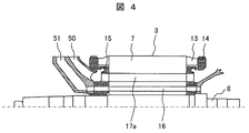
次に、本発明の回転電機の実施例3について、図4を用いて説明する。図4は、固定子2、ベアリング10及びハウジング11は、図示を省略している。
Next, a third embodiment of the rotating electrical machine of the present invention will be described with reference to FIG. In FIG. 4, the
該図に示す如く、実施例3が実施例1と異なる点は、回転子鉄心7に取り付けられた内扇ファン50と外扇ファン51が、一体の構造となっている点である。この一体構造の内扇ファン50と外扇ファン51は、押え板15に取り付けられている。
As shown in the figure, the third embodiment differs from the first embodiment in that the
このような本実施例によれば、実施例1と同様な効果が得られることは勿論、内扇ファン50と外扇ファン51が一体構造となることで、風量が増加するし、実施例1に比較して構造が簡単になり、低コスト化を図ることができる。
According to such a present Example, the effect similar to Example 1 can be acquired, and since the
次に、本発明の回転電機の実施例4について、図5を用いて説明する。図5は、固定子2、ベアリング10及びハウジング11は、図示を省略している。
Next, a fourth embodiment of the rotating electrical machine of the present invention will be described with reference to FIG. In FIG. 5, illustration of the
該図に示す如く、実施例4が実施例1と異なる点は、回転子鉄心7の押え板15に取り付けられた内扇ファン50が回転子3の一方の軸端に、外扇ファン51が回転子3の他方の軸端に設置されている構造としている点である。
As shown in the figure, the fourth embodiment differs from the first embodiment in that the
このような実施例によれば、実施例1と同様な効果が得られることは勿論、内扇ファン50と外扇ファン51を回転子3の両軸端に配置することで、軸方向端部のレイアウトを有効に活用することができ、更なる回転電機の小型化に寄与できる。
According to such an embodiment, the same effect as in the first embodiment can be obtained, and the
尚、内扇ファン50と外扇ファン51は、回転子鉄心7を軸方向から押えるに、回転子鉄心7の軸方向両端に配置されている押え板15とそれぞれ一体に構成されていても構わない。
Note that the
次に、本発明の回転電機の実施例5について、図6を用いて説明する。図6は、固定子2、ベアリング10、ハウジング11及び外扇ファン51は、図示を省略している。
Next, a fifth embodiment of the rotating electrical machine of the present invention will be described with reference to FIG. In FIG. 6, the
該図に示す如く、実施例5が実施例1と異なる点は、外気通風用の孔16が内気通風用の孔17aよりも回転子3の外周側としている点である。
As shown in the figure, the fifth embodiment differs from the first embodiment in that the outside
このような本実施例の構成とすることにより、外扇ファンによって取り込まれた外気は、押え板15を通り、外気通風用の孔16に導かれる。この際、押え板15には、内周側から外周側方向の径方向に斜め貫通孔15aが存在し、この斜め貫通孔15aによって、回転子3の外周部にある外気通風用の孔16に外気が入気される。また、外気通風用の孔16を通過した外気は、軸方向反対側の押え板15に通風され、外周側から内周側方向の径方向に斜め貫通孔15bによって機外へと排出される。
With this configuration of the present embodiment, the outside air taken in by the outside fan is guided to the outside
一方、内扇ファン50によって循環している内気は、外周側から内周側方向の径方向に斜めに開いた斜め貫通孔15cをもつ押え板15によって、回転子3の内周側にある内気通風用の孔17aに入気される。内気通風用の孔17aを通過した内気は、軸方向反対側の押え板15の内周側から外周側方向の径方向に斜めに開いた斜め貫通孔15dをもつ押え板15に通風される。
On the other hand, the internal air circulated by the
このような本実施例によれば、実施例1と同様な効果が得られることは勿論、発熱の大きな回転子バー13の近くに外気通風用の孔17aを配置できるため、回転子バー13の冷却を効果的に行うことができ、回転電機の冷却性能を向上できる。
According to the present embodiment, the same effect as that of the first embodiment can be obtained, and the
次に、本発明の回転電機の実施例6について、図7を用いて説明する。図7は、本発明の回転電機を永久磁石式回転電機とした場合である。 Next, a sixth embodiment of the rotating electrical machine of the present invention will be described with reference to FIG. FIG. 7 shows a case where the rotating electrical machine of the present invention is a permanent magnet rotating electrical machine.
該図に示す如く、実施例6が実施例1と異なる点は、実施例1では誘導機の例でとして回転子バーを回転子3に使用していたが、本実施例では、回転子バーに代えて回転子3に永久磁石23を使用していることである。
As shown in the figure, the sixth embodiment differs from the first embodiment in that the rotor bar is used for the
即ち、本実施例では、回転子鉄心7の磁石挿入孔に、周方向に所定間隔をもち、かつ、軸方向に伸延するように複数個の界磁部材である永久磁石23を設けたものである。他の構成は、図1の構成と同様である。
That is, in this embodiment, a plurality of
このような本実施例によれば、実施例1と同様な効果が得られることは勿論、外気56が外気通風用の孔16を通り、かつ、内気57が内気通風用の孔17aを通ることで永久磁石23の発熱を抑えることができるので、永久磁石23が熱減磁する恐れがなくなり、しかも、内気57の冷却も行うことができるため、永久磁石式回転電機の冷却性能を向上することができる。
According to the present embodiment, the same effect as in the first embodiment can be obtained, and the
尚、本発明は、分布巻方式の回転電機、或いは集中巻方式の回転電機の両者においても適用できることは言うまでもない。 Needless to say, the present invention can be applied to both a distributed winding type rotating electrical machine and a concentrated winding type rotating electrical machine.
次に、本発明の実施例7として、本発明の上述した各実施例のうちの1つの回転電機を用いた鉄道車両について、図8を用いて説明する。 Next, as a seventh embodiment of the present invention, a railway vehicle using one rotating electrical machine in the above-described embodiments of the present invention will be described with reference to FIG.
該図に示す如く、鉄道車両200は、台車201に実施例1乃至6のいずれか1つの回転電機1、増速ギア202、車輪203を備えて構成され、回転電機1が増速ギア202を介して車輪203を駆動するものである。
As shown in the figure, the
尚、回転電機1は、本実施例では2台だが、1台又は2台以上となる複数台を搭載し、駆動することも可能である。また、以上の説明では、回転電機1を鉄道車両200の車輪203の駆動に用いるものとして説明したが、電動建機用の駆動装置及び他あらゆる駆動装置においても使用できるものである。
Note that although there are two rotating
このような本実施例によれば、本発明の回転電機を電動車両、特に、鉄道車両に適用することで、回転電機の小型化が図れているため、出力が大きな鉄道車両を提供することができる。 According to such a present Example, since the rotary electric machine can be reduced in size by applying the rotary electric machine of the present invention to an electric vehicle, in particular, a railway vehicle, it is possible to provide a railway vehicle having a large output. it can.
次に、本発明の実施例8として、本発明の上述した各実施例のうちの1つの回転電機を用いた電気自動車について、図9を用いて説明する。 Next, as an eighth embodiment of the present invention, an electric vehicle using one rotating electric machine among the above-described embodiments of the present invention will be described with reference to FIG.
該図に示す如く、電気自動車の車体100は、4つの車輪110、112、114、116によって支持されている。この電気自動車は、前輪駆動であるため、前方の車軸154には、実施例1乃至6のいずれか1つの回転電機1が直結して取り付けられている。
As shown in the figure, the
回転電機1は、制御装置130によって駆動トルクが制御される。制御装置130の動力源としては、バッテリ151が備えられ、このバッテリ151から電力が制御装置130を介して、回転電機1に供給され、回転電機1が駆動されて、車輪110、114が回転する。ハンドル150の回転は、ステアリングギア152及びタイロッド、ナックルアーム等からなる伝達機構を介して、2つの車輪110、114に伝達され、車輪の角度が変えられる。
The rotating
このような本実施例によれば、本発明の回転電機を電動車両、特に、電気自動車に適用すれば、回転電機の小型化が図れているため、出力が大きな電気自動車を提供することができる。 According to the present embodiment, if the rotating electrical machine of the present invention is applied to an electric vehicle, particularly an electric vehicle, the rotating electrical machine can be reduced in size, so that an electric vehicle having a large output can be provided. .
1…回転電機、2…固定子、3…回転子、4…固定子鉄心、5…固定子巻線、6…回転子スロット、7…回転子鉄心、8…シャフト、9…エンドブラケット、10…ベアリング、11…ハウジング、12…固定子スロット、13…回転子バー、14…エンドリング、15…押え板、15a、15b、15c、15d…斜め貫通孔、16…外気通風用の孔、17a…内気通風用の孔、17b…内気通風用ダクト、18…コイルエンド、19…シャフト孔、20…羽根、21…ヨーク部、22…ティース部、23…永久磁石、50…内扇ファン、51…外扇ファン、52…空気溜まり部、53…粉塵排出口、54…外気入気口、55…外気排出口、56…外気、57…内気、100…車体、110、112、114、116、203…車輪、130…制御装置、150…ハンドル、151…バッテリ、152…ステアリングギア、154…車軸、200…鉄道車両、201…台車、202…増速ギア。
DESCRIPTION OF
Claims (10)
前記回転子鉄心に、機外の空気を通風するための外気通風用の孔と、機内の空気を通風するための内気通風用の孔とを備え、前記外気通風用の孔は、前記内気通風用の孔よりも前記回転子の外周側に位置し、かつ、前記外扇ファンによって外気入気口から外気が入気されると共に、前記外扇ファンの遠心力によって粉塵排出口から粉塵が排出された前記外気が前記外気通風用の孔を通り、前記内気通風用の孔を通る機内空気を前記回転子鉄心を介して冷却しながら外気排出口から排出されることを特徴とする回転電機。 The stator is composed of a stator and a rotor arranged opposite to the inner diameter side of the stator via a predetermined gap. The stator extends in the axial direction on the inner diameter side of the stator core and the stator core. A plurality of stator slots formed at a predetermined interval in the circumferential direction, and a stator coil mounted in the plurality of stator slots, the rotor comprising a rotor core and an outer periphery of the rotor core A plurality of rotor slots extending in the axial direction and having a predetermined interval in the circumferential direction, a field member inserted in the rotor slot, an internal fan for internal air ventilation, and an external fan for external air ventilation In a rotating electrical machine with a fan,
The rotor core is provided with a hole for ventilating outside air for ventilating air outside the machine, and a hole for ventilating inside air for ventilating the air inside the machine, and the hole for ventilating outside air is the inside air ventilating hole. The outside fan is located on the outer peripheral side of the rotor with respect to the hole for the outside , and outside air is introduced from the outside air inlet by the outside fan , and dust is discharged from the dust outlet by the centrifugal force of the outside fan. The rotating electrical machine is characterized in that the outside air that has passed through the outside air ventilation hole is discharged from the outside air outlet while cooling the in-machine air that passes through the inside air ventilation hole through the rotor core.
前記回転子鉄心に、機外の空気を通風するための外気通風用の孔と、機内の空気を通風するための内気通風用の孔とを備え、前記外気通風用の孔は、前記内気通風用の孔よりも前記回転子の外周側に位置し、かつ、前記外扇ファンによって外気入気口から外気が入気されると共に、前記外扇ファンの遠心力によって粉塵排出口から粉塵が排出された前記外気が前記外気通風用の孔を通り、前記内気通風用の孔を通る機内空気を前記回転子鉄心を介して冷却しながら外気排出口から排出されることを特徴とする回転電機。 The stator is composed of a stator and a rotor arranged opposite to the inner diameter side of the stator via a predetermined gap. The stator extends in the axial direction on the inner diameter side of the stator core and the stator core. A plurality of stator slots formed at a predetermined interval in the circumferential direction, and a stator coil mounted in the plurality of stator slots, the rotor comprising a rotor core and an outer periphery of the rotor core A plurality of rotor slots extending in the axial direction and having a predetermined interval in the circumferential direction; rotor bars inserted in the plurality of rotor slots; and the rotor bars at both shaft ends. In a rotating electrical machine comprising an end ring that is short-circuited, a shaft into which the rotor iron core is fitted, an internal fan for internal air ventilation, and an external fan for external air ventilation,
The rotor core is provided with a hole for ventilating outside air for ventilating air outside the machine, and a hole for ventilating inside air for ventilating the air inside the machine, and the hole for ventilating outside air is the inside air ventilating hole. The outside fan is located on the outer peripheral side of the rotor with respect to the hole for the outside , and outside air is introduced from the outside air inlet by the outside fan , and dust is discharged from the dust outlet by the centrifugal force of the outside fan. The rotating electrical machine is characterized in that the outside air that has passed through the outside air ventilation hole is discharged from the outside air outlet while cooling the in-machine air that passes through the inside air ventilation hole through the rotor core.
前記回転子鉄心に、機外の空気を通風するための外気通風用の孔と、機内の空気を通風するための内気通風用の孔とを備え、前記外気通風用の孔は、前記内気通風用の孔よりも前記回転子の外周側に位置し、かつ、前記外扇ファンによって外気入気口から外気が入気されると共に、前記外扇ファンの遠心力によって粉塵排出口から粉塵が排出された前記外気が前記外気通風用の孔を通り、前記内気通風用の孔を通る機内空気を前記回転子鉄心を介して冷却しながら外気排出口から排出されることを特徴とする回転電機。 The stator is composed of a stator and a rotor arranged opposite to the inner diameter side of the stator via a predetermined gap. The stator extends in the axial direction on the inner diameter side of the stator core and the stator core. A plurality of stator slots formed at a predetermined interval in the circumferential direction, and a stator coil mounted in the plurality of stator slots, the rotor including a rotor core and the rotor core; A plurality of magnet insertion holes extending in the axial direction and formed at predetermined intervals in the circumferential direction; permanent magnets inserted into the plurality of magnet insertion holes; a shaft into which the rotor core is fitted; In a rotating electrical machine provided with an internal fan for air and an external fan for ventilating outside air,
The rotor core is provided with a hole for ventilating outside air for ventilating air outside the machine, and a hole for ventilating inside air for ventilating the air inside the machine, and the hole for ventilating outside air is the inside air ventilating hole. The outside fan is located on the outer peripheral side of the rotor with respect to the hole for the outside , and outside air is introduced from the outside air inlet by the outside fan , and dust is discharged from the dust outlet by the centrifugal force of the outside fan. The rotating electrical machine is characterized in that the outside air that has passed through the outside air ventilation hole is discharged from the outside air outlet while cooling the in-machine air that passes through the inside air ventilation hole through the rotor core.
前記回転子の内周部の前記外気通風用の孔及び内気通風用の孔は、周方向にスキューが施されていると共に、前記外気通風用の孔及び前記内気通風用の孔の入り口付近の前記回転子鉄心を軸方向から押える押え板に羽根が設けられ、前記回転子の回転によって前記羽根を介して前記外気通風用の孔及び前記内気通風用の孔に空気が通風されることを特徴とする回転電機。 The rotating electrical machine according to any one of claims 1 to 3 ,
The outside air ventilation hole and the inside air ventilation hole in the inner circumferential portion of the rotor are skewed in the circumferential direction, and are located near the entrance of the outside air ventilation hole and the inside air ventilation hole. A blade is provided on a presser plate that presses the rotor iron core in the axial direction, and air is passed through the blade to the outside air ventilation hole and the inside air ventilation hole through the blade by the rotation of the rotor. Rotating electric machine.
前記内扇ファンと外扇ファンは、一体構造になっていることを特徴とする回転電機。 The rotating electrical machine according to any one of claims 1 to 4 ,
The rotating electric machine is characterized in that the inner fan fan and the outer fan fan have an integral structure.
前記内扇ファンが前記回転子の一方の軸端に、前記外扇ファンが前記回転子の他方の軸端に配置されていることを特徴とする回転電機。 The rotating electrical machine according to any one of claims 1 to 4 ,
The rotating electric machine characterized in that the inner fan fan is disposed at one axial end of the rotor and the outer fan fan is disposed at the other axial end of the rotor.
前記内扇ファン及び外扇ファンは、前記回転子鉄心を軸方向から押えるために、該回転子鉄心の軸方向両端に配置されている押え板と一体に構成されていることを特徴とする回転電機。 In the rotating electrical machine according to claim 6 ,
The inner fan fan and the outer fan fan are configured integrally with presser plates disposed at both axial ends of the rotor core in order to press the rotor core from the axial direction. Electric.
前記外扇ファン及び前記内扇ファンは、前記回転子鉄心を軸方向から押えるための押え板とそれぞれ一体に構成されていることを特徴とする回転電機。 The rotating electrical machine according to claim 7 ,
The rotating electric machine characterized in that the outer fan fan and the inner fan fan are each integrally formed with a pressing plate for pressing the rotor core from the axial direction.
前記回転電機は、請求項1乃至8のいずれか1項に記載の回転電機であることを特徴とする鉄道車両。 In a railway vehicle comprising a carriage, a rotating electrical machine, a speed increasing gear, and a wheel, wherein the rotating electrical machine drives the wheel via the speed increasing gear,
The railway vehicle according to any one of claims 1 to 8 , wherein the rotating electrical machine is the rotating electrical machine according to any one of claims 1 to 8 .
前記回転電機は、請求項1乃至8のいずれか1項に記載の回転電機であることを特徴とする電動車両。 In an electric vehicle comprising a vehicle body, a wheel, an axle, and a rotating electric machine, wherein the wheel is driven by the rotating electric machine directly connected to the axle,
The rotary electric machine, an electric vehicle, which is a rotating electric machine according to any one of claims 1 to 8.
Priority Applications (3)
| Application Number | Priority Date | Filing Date | Title |
|---|---|---|---|
| JP2011274046A JP5879116B2 (en) | 2011-12-15 | 2011-12-15 | Rotating electric machine, railway vehicle including the same, and electric vehicle |
| CN201210544438.7A CN103166340B (en) | 2011-12-15 | 2012-12-14 | Rotating electric machine, rail vehicle and electric vehicle equipped therewith |
| EP12197185.7A EP2605380B1 (en) | 2011-12-15 | 2012-12-14 | Rotating electric machine, rail vehicle and electric vehicle equipped therewith |
Applications Claiming Priority (1)
| Application Number | Priority Date | Filing Date | Title |
|---|---|---|---|
| JP2011274046A JP5879116B2 (en) | 2011-12-15 | 2011-12-15 | Rotating electric machine, railway vehicle including the same, and electric vehicle |
Publications (2)
| Publication Number | Publication Date |
|---|---|
| JP2013126309A JP2013126309A (en) | 2013-06-24 |
| JP5879116B2 true JP5879116B2 (en) | 2016-03-08 |
Family
ID=47358008
Family Applications (1)
| Application Number | Title | Priority Date | Filing Date |
|---|---|---|---|
| JP2011274046A Active JP5879116B2 (en) | 2011-12-15 | 2011-12-15 | Rotating electric machine, railway vehicle including the same, and electric vehicle |
Country Status (3)
| Country | Link |
|---|---|
| EP (1) | EP2605380B1 (en) |
| JP (1) | JP5879116B2 (en) |
| CN (1) | CN103166340B (en) |
Families Citing this family (22)
| Publication number | Priority date | Publication date | Assignee | Title |
|---|---|---|---|---|
| JP6016722B2 (en) * | 2013-07-03 | 2016-10-26 | 三菱電機株式会社 | Electric motor core, rotary electric motor, and linear motor |
| JP2015100197A (en) * | 2013-11-19 | 2015-05-28 | 東芝三菱電機産業システム株式会社 | Rotor of rotary electric machine |
| CN103607073B (en) * | 2013-11-30 | 2015-11-04 | 永济新时速电机电器有限责任公司 | The independent three wind path structure motors of high efficiency cooling heat radiation |
| DE102014101039A1 (en) | 2014-01-29 | 2015-07-30 | Dr. Ing. H.C. F. Porsche Aktiengesellschaft | Electric machine |
| PL2916438T3 (en) * | 2014-03-05 | 2017-07-31 | Lappeenrannan Teknillinen Yliopisto | An electrical turbo-machine and a power plant |
| US10161416B2 (en) * | 2014-06-02 | 2018-12-25 | Hamilton Sundstrand Corporation | Rotary machine heat sink |
| CN104218736A (en) * | 2014-10-10 | 2014-12-17 | 永济新时速电机电器有限责任公司 | Self-ventilation asynchronous motor with large induced draught fan |
| EP3208913A1 (en) * | 2016-02-22 | 2017-08-23 | Siemens Aktiengesellschaft | Rotor of a permanently excited dynamoelectric rotating machine and its use |
| DE102016210930B4 (en) | 2016-06-20 | 2021-10-07 | Vitesco Technologies GmbH | Electric machine |
| EP3396816A1 (en) * | 2017-04-27 | 2018-10-31 | Hitachi, Ltd. | Rotary electric machine, rotary electric machine driving system and railway vehicle |
| CN108566043B (en) * | 2018-05-24 | 2019-12-06 | 深圳宇信和科技有限公司 | New energy automobile motor that radiating effect is good |
| CN208209683U (en) * | 2018-05-25 | 2018-12-07 | 苏州优德通力科技有限公司 | A kind of air-cooled anti-spray electric machine structure |
| JP7038074B2 (en) * | 2019-03-22 | 2022-03-17 | 東芝三菱電機産業システム株式会社 | Rotating machine and rotor shaft |
| CN112713712A (en) * | 2020-12-14 | 2021-04-27 | 中车永济电机有限公司 | Direct drive motor of oil field winch |
| EP4016813A1 (en) * | 2020-12-17 | 2022-06-22 | Rolls-Royce Deutschland Ltd & Co KG | Electric motor with a cooling device |
| DE102020216225A1 (en) * | 2020-12-18 | 2022-06-23 | Zf Friedrichshafen Ag | Electrical machine for driving a motor vehicle |
| FR3128078A1 (en) | 2021-10-12 | 2023-04-14 | Nidec Psa Emotors | Flange for rotating electrical machine |
| CN113937953A (en) * | 2021-10-22 | 2022-01-14 | 中车株洲电机有限公司 | Active air supply cooling permanent magnet motor and electric locomotive |
| CN113949188A (en) * | 2021-10-22 | 2022-01-18 | 中车株洲电机有限公司 | Rotor air-cooled permanent magnet motor and electric locomotive |
| DE102021212248A1 (en) | 2021-10-29 | 2023-05-04 | Valeo Eautomotive Germany Gmbh | Rotor for an electric machine with improved cooling |
| CN115664066A (en) * | 2022-09-09 | 2023-01-31 | 中车株洲电机有限公司 | Motor stator structure and motor |
| JP7450836B1 (en) | 2023-06-07 | 2024-03-15 | 三菱電機株式会社 | rotating electric machine |
Family Cites Families (17)
| Publication number | Priority date | Publication date | Assignee | Title |
|---|---|---|---|---|
| GB328661A (en) * | 1928-11-05 | 1930-05-05 | Donald Bright Hoseason | Improvements in electric motors |
| GB467527A (en) * | 1936-03-27 | 1937-06-18 | Mather & Platt Ltd | Improvements relating to the cooling of dynamo electric machines |
| GB826423A (en) * | 1957-01-28 | 1960-01-06 | Vickers Electrical Co Ltd | Improvements relating to the cooling of flame proof motors |
| FR2349228A1 (en) * | 1976-04-21 | 1977-11-18 | Sabev Todor | Async. motor with cage rotor - has water cooled stator and air cooled rotor enabling higher power operation |
| JPH066958A (en) * | 1992-06-17 | 1994-01-14 | Hitachi Ltd | Main motor for vehicle |
| JPH0865933A (en) * | 1994-08-11 | 1996-03-08 | Matsushita Electric Ind Co Ltd | Rotor core of motor |
| JPH09149599A (en) | 1995-11-27 | 1997-06-06 | Hitachi Ltd | Totally enclosed rotating electric machine |
| JP3825679B2 (en) | 2001-10-31 | 2006-09-27 | 東芝トランスポートエンジニアリング株式会社 | Fully enclosed outer fan motor for vehicles |
| CN2572651Y (en) * | 2002-09-30 | 2003-09-10 | 永济电机厂 | DC motor |
| JP2004352196A (en) * | 2003-05-30 | 2004-12-16 | Aruze Corp | Electric vehicle suspension mechanism |
| JP2005312097A (en) * | 2004-04-16 | 2005-11-04 | Toshiba Corp | Motor |
| JP4686228B2 (en) * | 2005-03-23 | 2011-05-25 | 株式会社東芝 | Fully enclosed fan motor |
| JP2006340571A (en) * | 2005-06-06 | 2006-12-14 | Toshiba Corp | Electric motor for vehicle |
| JP4627788B2 (en) * | 2008-06-27 | 2011-02-09 | 株式会社日立製作所 | Permanent magnet rotating electric machine |
| CN101521427A (en) * | 2008-11-15 | 2009-09-02 | 永济新时速电机电器有限责任公司 | Self-ventilation pulling motor |
| DE102009051651B4 (en) * | 2009-11-02 | 2012-01-26 | Siemens Aktiengesellschaft | Wind power generator with internal cooling circuit |
| JP2011166908A (en) * | 2010-02-08 | 2011-08-25 | Toshiba Corp | Totally enclosed motor |
-
2011
- 2011-12-15 JP JP2011274046A patent/JP5879116B2/en active Active
-
2012
- 2012-12-14 CN CN201210544438.7A patent/CN103166340B/en not_active Expired - Fee Related
- 2012-12-14 EP EP12197185.7A patent/EP2605380B1/en active Active
Also Published As
| Publication number | Publication date |
|---|---|
| EP2605380A2 (en) | 2013-06-19 |
| CN103166340B (en) | 2015-07-22 |
| CN103166340A (en) | 2013-06-19 |
| EP2605380B1 (en) | 2019-02-20 |
| JP2013126309A (en) | 2013-06-24 |
| EP2605380A3 (en) | 2017-12-06 |
Similar Documents
| Publication | Publication Date | Title |
|---|---|---|
| JP5879116B2 (en) | Rotating electric machine, railway vehicle including the same, and electric vehicle | |
| JP6198085B2 (en) | Iron-free rotating electric machine including a stator having a cylindrical coil and its cooling method | |
| US8648505B2 (en) | Electrical machine with multiple cooling flows and cooling method | |
| JP6059906B2 (en) | Axial gap type rotating electrical machine | |
| JP2016154440A5 (en) | ||
| JP2013074646A (en) | Motor integrated with controller | |
| JP5548046B2 (en) | Permanent magnet rotating electric machine | |
| US20210194303A1 (en) | Rotor of a Permanent-Magnet Dynamoelectric Rotary Machine | |
| US9755467B2 (en) | Open-type induction motor | |
| JP2014033584A (en) | Wind cooling structure of rotary electric machine | |
| CN102055280A (en) | Brushless rotary electric machine | |
| JP2004312898A (en) | Rotor, stator, and rotating machine | |
| JP6007951B2 (en) | Rotating electric machine | |
| JP4928986B2 (en) | Fully closed electric motor for vehicle drive | |
| JP2008043149A (en) | Motor cooling structure | |
| JP5787184B2 (en) | Rotor and rotating electric machine using the same | |
| JP2014158342A (en) | Dynamo-electric machine | |
| JP2008086164A (en) | Totally-enclosed external fan type motor | |
| JP2021197826A (en) | Rotating machine | |
| CN111628589B (en) | Rotary electric machine | |
| JP5723855B2 (en) | Rotating electric machine | |
| JP7137543B2 (en) | Rotating electric machine | |
| JP6827198B2 (en) | Brushless motors and power tools | |
| JP2017034942A (en) | Rotary electric machine | |
| WO2019082488A1 (en) | Rotary electric machine and electrical motor vehicle provided with same |
Legal Events
| Date | Code | Title | Description |
|---|---|---|---|
| A621 | Written request for application examination |
Free format text: JAPANESE INTERMEDIATE CODE: A621 Effective date: 20140718 |
|
| A977 | Report on retrieval |
Free format text: JAPANESE INTERMEDIATE CODE: A971007 Effective date: 20150512 |
|
| A131 | Notification of reasons for refusal |
Free format text: JAPANESE INTERMEDIATE CODE: A131 Effective date: 20150519 |
|
| A521 | Written amendment |
Free format text: JAPANESE INTERMEDIATE CODE: A523 Effective date: 20150721 |
|
| A131 | Notification of reasons for refusal |
Free format text: JAPANESE INTERMEDIATE CODE: A131 Effective date: 20151110 |
|
| A521 | Written amendment |
Free format text: JAPANESE INTERMEDIATE CODE: A523 Effective date: 20151221 |
|
| TRDD | Decision of grant or rejection written | ||
| A01 | Written decision to grant a patent or to grant a registration (utility model) |
Free format text: JAPANESE INTERMEDIATE CODE: A01 Effective date: 20160119 |
|
| A61 | First payment of annual fees (during grant procedure) |
Free format text: JAPANESE INTERMEDIATE CODE: A61 Effective date: 20160201 |
|
| R150 | Certificate of patent or registration of utility model |
Ref document number: 5879116 Country of ref document: JP Free format text: JAPANESE INTERMEDIATE CODE: R150 |
|
| S111 | Request for change of ownership or part of ownership |
Free format text: JAPANESE INTERMEDIATE CODE: R313111 |
|
| R350 | Written notification of registration of transfer |
Free format text: JAPANESE INTERMEDIATE CODE: R350 |